1. Introduction
Since the 1980s, when micro-electro-mechanical-systems (MEMS) were initially commercialized, the demands for these tiny devices have increased dramatically. This is principally due to their outstanding properties (mechanical, electrical, thermal, etc.) as well as their unique features (small sizes, easiness in fabrication, etc.). While they were used in the beginning mainly as sensors and actuators, they are nowadays designed to be used in many other engineering applications [
1]. To cite few, they are being used as pressure sensors [
2,
3], accelerometers [
4,
5], microphones in cellphones [
6], micro-mirrors in plasma TVs [
7], GPS [
8] and many other useful applications. Moreover, they are still being continuously explored by scientists and researchers, and these developments will hopefully lead to more useful features and become even more important in life.
In the MEMS community, there are many different types of structures available and the selection depends on the type of the application. For example, clamped-clamped microbeams form one of the basic structures configurations for building MEMS devices. They have various preferred features such as: easiness in the fabrication, high sensitivity, cost effectiveness, etc., make them very attractive in many MEMS-related applications. Furthermore, their fabrication process is somehow trivial and can be done by using the basic bulk and surface micromachining techniques [
9,
10]. Moreover, the natural frequencies of the clamped-clamped microbeam are relatively higher as compared to other microstructures such as cantilever or simply-supported microbeams. This feature is desirable in increasing the sensitivity of the microstructures to be used as Radio Frequency (RF) filters [
11], RF switches [
12] and resonant sensors [
13]. Furthermore, the linear dynamic range of clamped-clamped micro-beams is lower compared to micro-cantilevers [
14]. In addition to that, a lot of researches proved that the performance of the clamped-clamped microbeam can be improved further. For example, Kacem et al. [
15] proved that by tuning the parameters linear behavior can be achieved up to the pull-in point, which could have a great impact on the sensors’ resolution. In addition, Kacem et al. [
16] showed helpful analysis to enhance the sensors either by avoiding instability branches or gaining some desired features. In another work, Kacem et al. [
17] developed a method to improve the frequency stability and the sensing of the resonators. The clamped-clamped microbeam configuration possesses numerous applications and to mention some of them the projection display arrays [
18], optical fibers [
19] and thermal actuators [
20].
Another common configuration of microbeam based MEMS devices is the parallel-plates actuator made from a single movable/flexible electrode. The use of this type of configuration provides an extended range of travel compared to others, however with high power consumption and switching time. These latter specifications are needed in many applications but not for others, where more desirable features and better performing structures are required. One of the suggested alternatives is the use of multi-layers based actuator instead of only one layer (movable electrode) based MEMS actuators.
There are few research groups discussed the applications for the double-microbeam. For example, Afrang et al. [
21] suggested the double-microbeam actuator to be used in micro-machined switches application. Since, it has lower actuation voltage without high effect on the switching time. In addition, Chaffey et al. [
22] recommended the double cantilever microbeam for the tunable micro-cantilever switches. This is due to the fact that it requires lesser voltage to reach to the pull-in voltage than other single structures. In addition, Samaali et al. [
23] assured that the use of double-microbeam helps in reducing the actuation voltage and the static pull in voltage, which makes this structure powerful for RF-MEMS switches. Additionally, Ouakad et al. [
24] mentioned that the use of double-microbeam is helpful for applications that require large response. Therefore, it is clear that assuming a double-microbeam, or even multi-layers configuration, may increase the deflection of the microbeam with the same voltage that is provided in a single microbeam. As a result, it might help reducing the power consumption and the switching time for these types of applications where large deformation is needed with minor power consumption as well lower switching time.
It is clear from the afore-summarized literature review that it is important to study the structural behavior of electrically coupled double-microbeams MEMS actuator. More scopes may still be discovered that may open new perspectives of MEMS actuators of interesting features, or even inventing new smart MEMS devices of improved structural and electrical behaviors. This paper will shed light on a simple model of double-microbeam configuration. First, the problem formulation of this system will be discussed, and followed by the reduced-order modeling (ROM) derivation. Then, the static analysis of the system will be presented and a parametric study on the air gap depths will be undertaken. Finally, the eigenvalue problem will be solved to variation of the natural frequencies and the mode shapes of the system will be discussed.
2. Problem Formulation
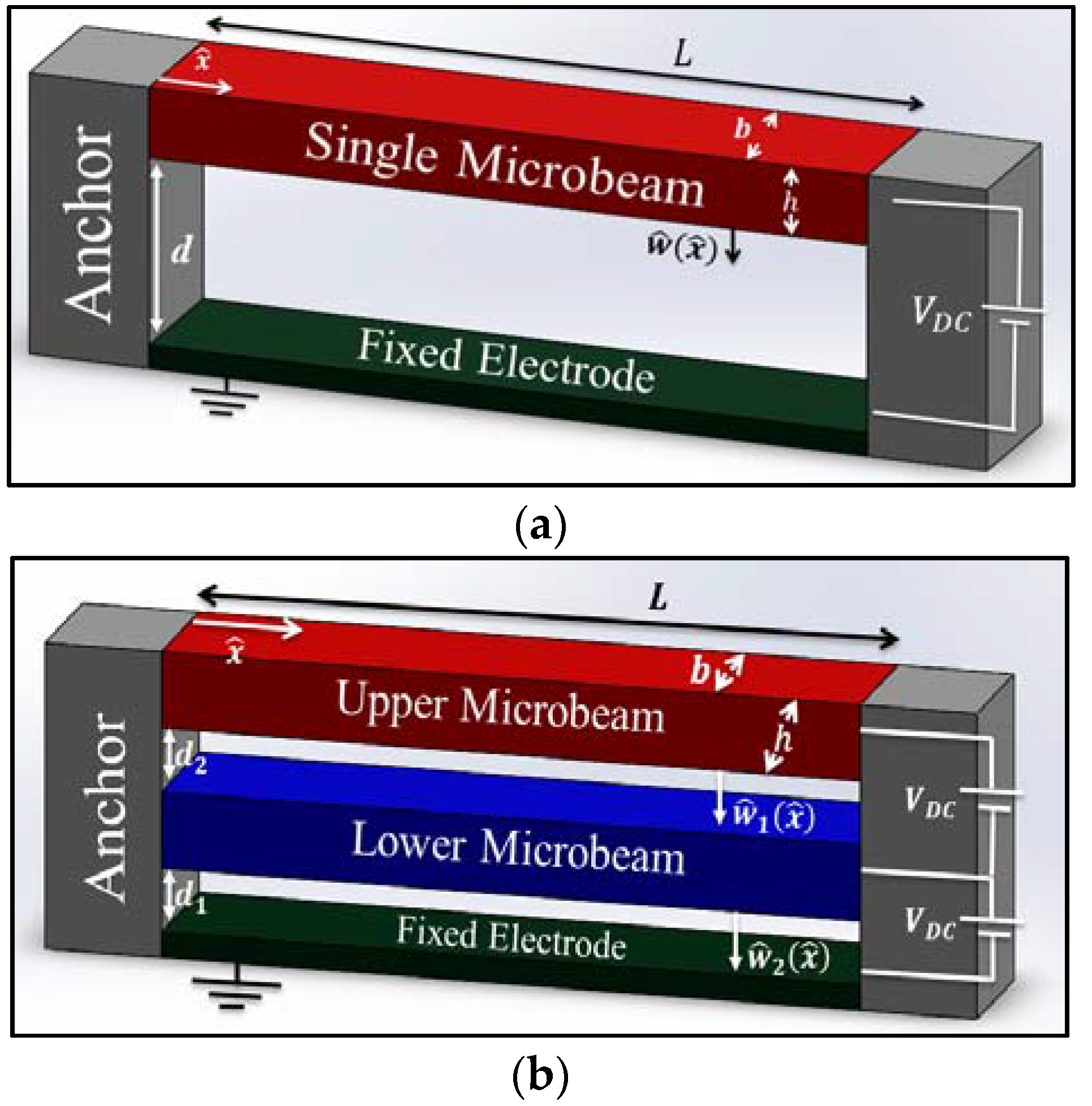
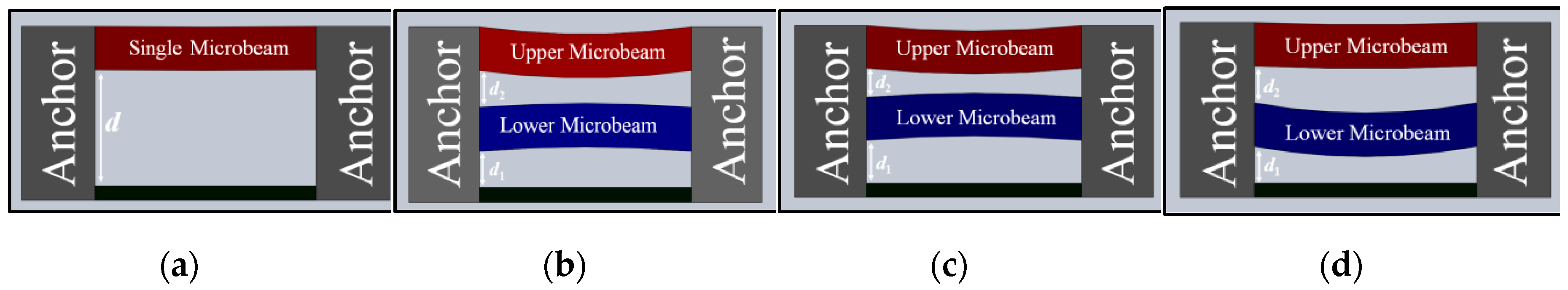
To be able to compare both actuator configurations, we will consider both models for a single-microbeam MEMS based actuator configuration and a double-microbeam configuration are shown in
Figure 1a,b, respectively. All shown microbeams in both models are assumed to be clamped-clamped and actuated by a parallel-plates DC bias of amplitude
(VDC) in Volt. For the double microbeam configuration, we consider dielectric layers for each electric field.
Assuming the so-called Newton second law under the assumption of the Euler Bernoulli’s shallow-thin beam theory, the governing static equation of motion for the single-microbeam configuration of
Figure 1a and its respective boundary conditions can be written as [
25]:
where:
E is the microbeam Young’s modulus of elasticity;
is its mass density;
is its moment of inertia, where
b and
h are its respective width and the thickness, respectively;
is its static deflection function;
is its cross sectional area;
is its initial length;
is the parallel-plates capacitor dielectric constant; and
is its initial air gap depth.
For the double-microbeams configuration shown in
Figure 1b, the lower and upper microbeams static equations are respectively given as:
and their respective boundary conditions are set as follows:
where:
are the static deflections of each microbeam and
are the two different air gaps for both parallel-plates capacitors.
As it is more convenient to handle calculations and resolutions of equations in the micro-scale in normalized form, we write the above equations of motion in non-dimensional form while assuming the following non-dimensional variables:
Now, substituting Equation (5) into Equations (1)–(4) result into the following normalized equations of motion and their respective boundary conditions:
For the single-microbeam based actuator:
For the double-microbeams based actuator:
where the nondimensional parameters assumed in Equations (6)–(9) are defined as follows:
,
,
,
,
,
.
3. Reduced-Order Model (ROM)
To solve the nonlinear differential equations governing the structural behavior of the above described MEMS actuators, various methods can be assumed such as the Finite-Element Method [
26], the Finite-Difference Method [
27], Differential-Quadrature Method [
27], the Shooting Method [
28,
29], etc., which are considered to be computationally expensive and in some cases unstable since some rely on initial guesses. Another powerful technique is the so-called Galerkin expansion discretization which is mainly used to derive Reduced-Order Models (ROM) from distributed (continuous) systems. This method is a well-used technique in the literature of MEMS devices [
30].
As a result, in order to get the ROM, the previous equations, i.e., Equations (6)–(9), will be discretized using Galerkin method and this can be done by expanding the static deflections of the assumed microbeams as:
where the coefficients
ki,
fi, and
gi are time-independent constants and
are trial functions assumed to be the linear mode shapes of a clamped-clamped beam. To solve for the time-independent unknowns constants
ki,
fi, and
gi, it is essential to substitute Equation (10) into Equations (6)–(9), then multiply the outcome by
, and finally integrate the outcome from
x = 0 to
x = 1 while using the orthogonality of the mode shapes functions of a clamped-clamped beam. Following the previous procedure, we get the following reduced-order modeling equations bot both assumed actuators as follows:
For the single-microbeam based actuator:
For the double-microbeams based actuator:
4. Static Analysis
In this section, the static analysis for both single and double-microbeams configuration is carried out using the earlier derived ROM. The main problem with this approach is that the distributed electrostatic force comes in an integral form in the resulting ROM equations, and consequently this integral form is not easy to deal analytically due to nonlinearities arising from its denominator. As an attempt to overcome this challenge, some groups [
31,
32] used Taylor-series expansion procedure, which brings the nonlinearity to the numerator of the electrostatic force and hence simplifies the calculation of nonlinear ROM integrals. Others suggested multiplying the resultant equation of motion by the electrostatic force denominator and hence the evaluation of the integral in the ROM equation will not be problematic anymore [
25]. We adopted to use this latter approach which is numerically stable and more convenient in dealing with nonlinear forcing terms.
In order to ascertain the convergence of the implemented ROM, we start the calculation of the microbeams’ deflections with only one mode in the ROM. For the single microbeam, we solve for the
ki in Equation (11), whereas for double microbeam we solve for
fi, and
gi in the coupled Equation (12a,b), and this can be done by several methods like the harmonic balance method coupled with the asymptotic numerical method [
33,
34], which enables the capture of stable and unstable branches or using the so-called Newton’s method. We adopted the latter approach by using the command FindRoot in Mathematica software. Then increase the number of assumed modes in the ROM by one. The previous steps are to be repeated until the maximum deflection variation with
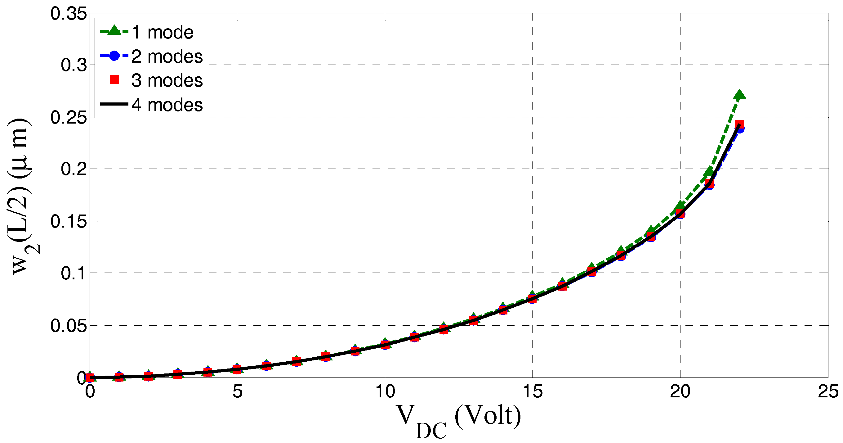
VDC for both microbeams is converging. The maximum deflection of the upper microbeam is presented versus the applied DC voltage in
Figure 2 for the case study of
Table 1. It can be noted from the graph that when the number of modes is increased the solution is varying slightly, until convergence is reached at almost three modes in the ROM.
Next, a parametric study is carried out to investigate the effect of changing the air gaps between the movable microbeams on their static profiles. Three different sets of air gaps are assumed, which are: 1.0, 1.25 and 1.5 µm and they were all restricted by the following condition (to be able to compare with the single-beam based actuator with initial gap of 4 µm):
Accordingly, three different cases were considered, which are:
Case 1: d1 = d2 (where both initial gaps are set equal to 1.25 μm)
Case 2: d1 > d2 (where d1 = 1.5 μm and d2 = 1.0 μm)
Case 3: d1 < d2 (where d1 = 1.0 μm and d2 = 1.5 μm)
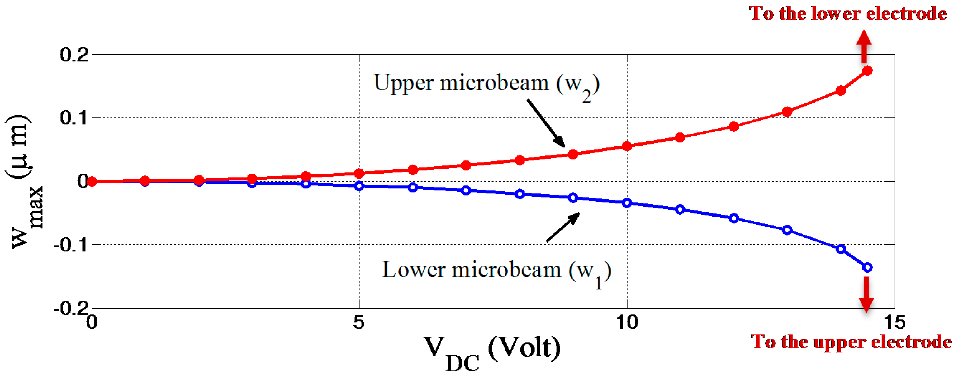
4.1. Case 1 (d1 = d2)
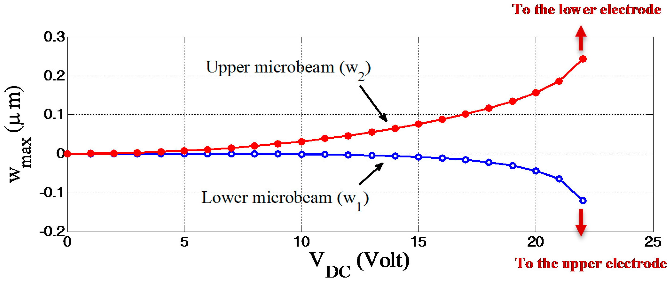
For this first case, the maximum static deflection versus the applied DC voltage for both microbeams (upper and lower) is presented in
Figure 3. It is clear from the figure that, the upper microbeam is deflected downward (positive value in
Figure 3), which seems to be reasonable, since the upper microbeam is affected by the force from the lower microbeam, which pulls it downward. In contrast, the lower microbeam is deflected upward (negative value in
Figure 3), which means that the force which results from the potential between the two microbeams is higher than the force from the fixed (stationary) electrode. In addition, the downward deflection for the upper microbeam is higher than the lower microbeam and it reaches pull-in first, which is about 23 Volt.
4.2. Case 2 (d1 > d2)
In this particular case, the behavior of the maximum static deflection for both microbeams is similar to the previous case, as displayed in
Figure 4. Again, the upper microbeam reaches the pull-in instability first at about 15 Volt. As compared to the previous case, the pull-in voltage is reduced and more deflection will occur in this case if similar voltages are assumed.
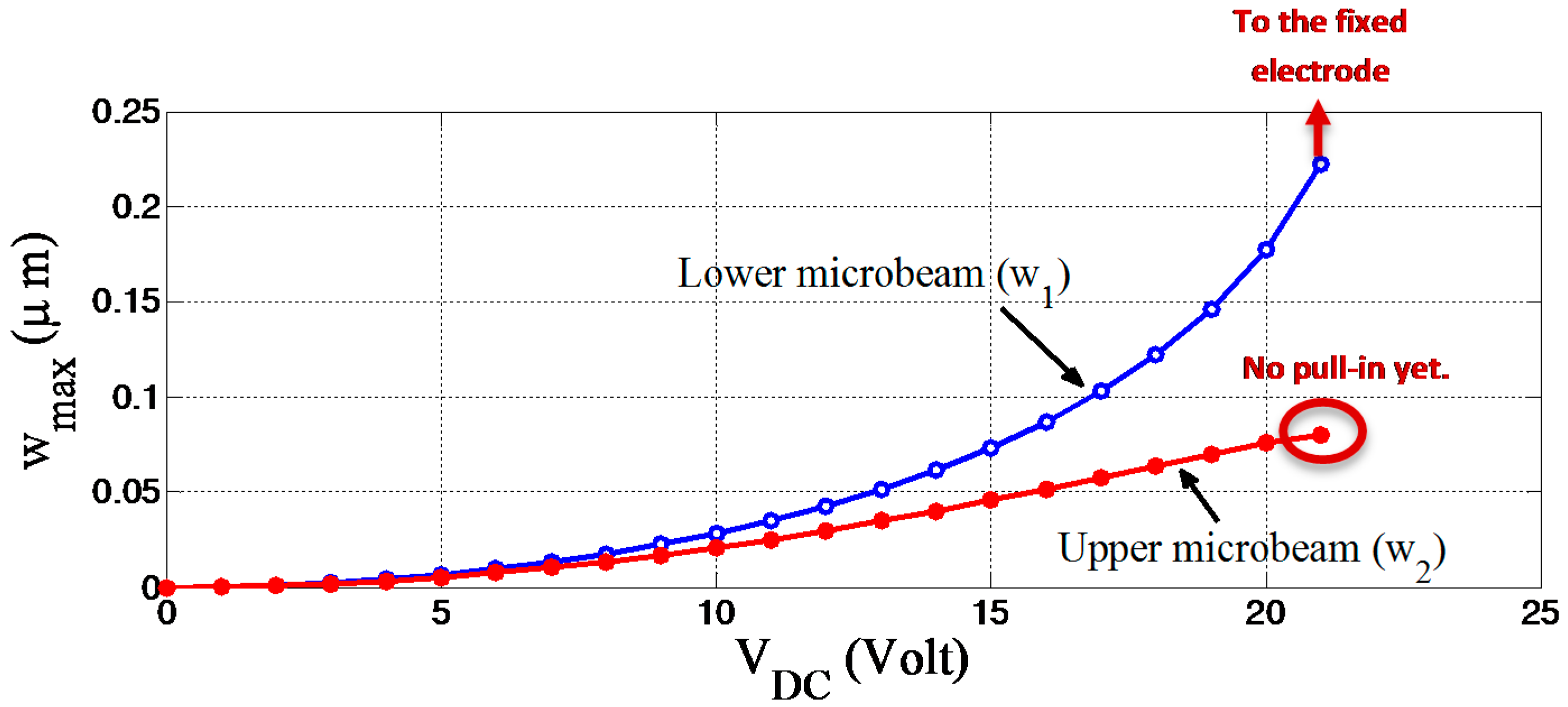
4.3. Case 3 (d1 < d2)
In this latter case, when calculating and then displaying the maximum static deflection versus the applied voltage, as shown in
Figure 5, we can identify some interesting and different outcomes in comparison to the two previously investigated cases. To mention a few, the lower microbeam, in this particular case, is deflected downward, which means the force resulting from the fixed electrode is higher than the force exerted by the upper microbeam. Furthermore, the magnitude of the deflection for the lower microbeam is higher than the upper and it reaches the pull-in instability first at about 23 Volt. Moreover, when the lower microbeam undergoes the pull-in instability (losses its stiffness) at around 23 Volt, the upper microbeam is still safe and possess some stiffness which states that it can be still used as actuator (with more range of travel).
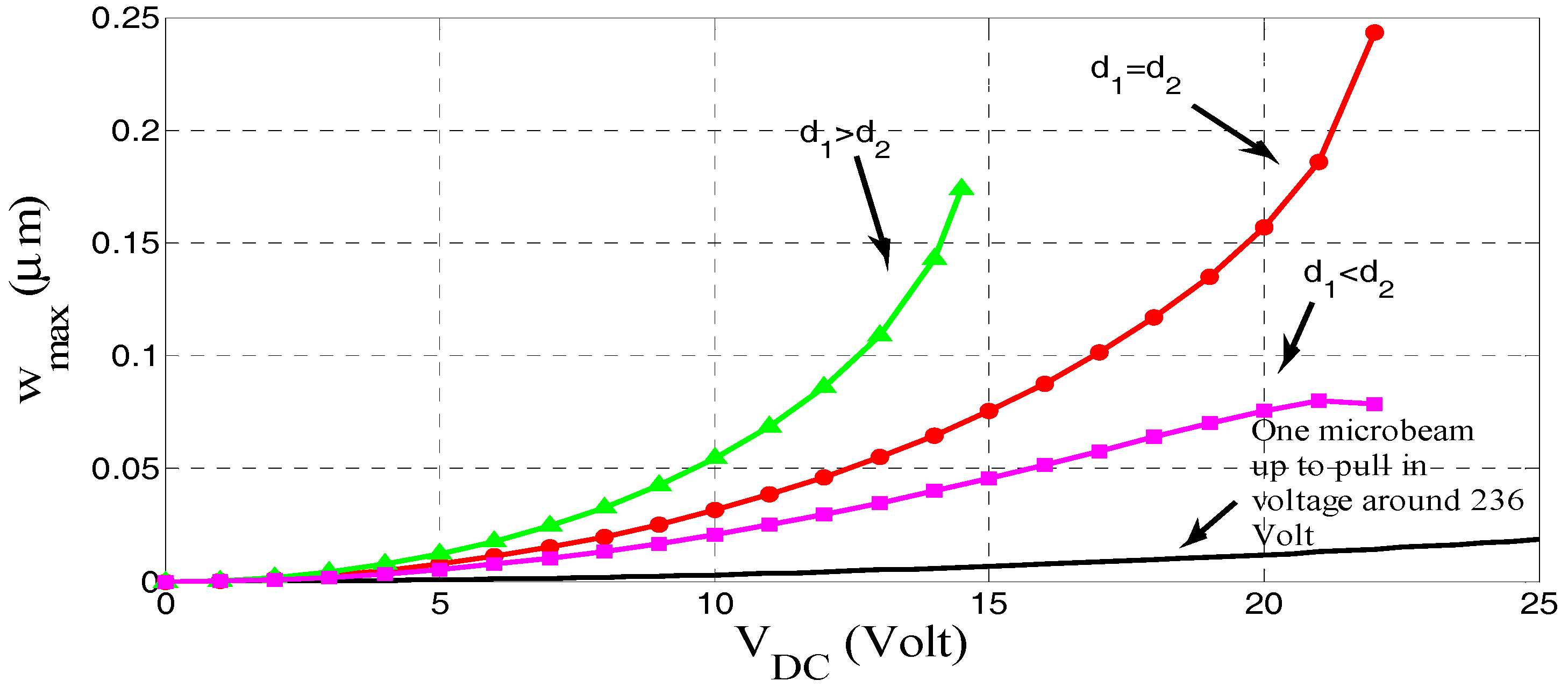
Finally, a comparison between the static deflection for the upper microbeam, when considering all three investigated cases as well as the case considering only single microbeam is presented in
Figure 6 and
Figure 7. Therefore, in all of the three investigated cases more deflection will be provided at the same voltage if assuming the double-microbeams rather than a single-microbeam arrangement. However, the pull-in voltage is reduced by a significant amount, since for the single-microbeam shape, the pull-in voltage is about 236 Volt. Hence, more stroke with lower power consumption.
Table 2 compares the pull-in voltage for the three cases with the single microbeam.
An insight into
Figure 6 reveals an interesting behavior. While, in all of the previous configurations for all points, increasing the voltage makes the upper microbeam approach the pull-in voltage faster, it can be seen that for the last point in configuration of
d1 <
d2 there is no such tendency. This strange behavior may be because the lower microbeam in this case is very close to the fixed electrode, and so the distance between the two microbeams will be higher. This makes the force between the two microbeams lower, and hence the upper microbeam will be far from the pull-in instability allowing it to still vibrate safely.
5. Natural Frequencies and Mode Shapes
In order to get the natural frequencies of the above considered MEMS based actuators, the inertia terms (
,
and
) will be included in the right hand side of both Equations (6) and (8), respectively. The subscript,
tt stands for the second time derivative with respect to the time variable
t. Thus, Equations (6) and (8) will be respectively adjusted to include these inertia effects as follows:
Subsequently, the deflections for single-microbeam based actuator as well as the lower and upper microbeams for the case of double-microbeams based actuator will be again discretized using the Galerkin expansion technique as follows:
where:
ki,
fi and
gi are the time-independents unknown constants that were calculated in the static analysis part and
β(t),
μi(t) and
νi(t) are time-dependent unknown functions. Details about the derivation of the single-microbeam based actuator can found in [
25]. We will focus next on the derivation of the equations governing the eigenvalue problem of the double-microbeams based actuator. Subsequently, and since we are in the process of developing the linear eigenvalue problem, the nonlinear electrostatic force terms in the derived ROM equations are to be linearized using the so-called Taylor series expansion. Therefore, neglecting all of the higher order terms to obtain:
where,
is known as the Jacobian matrix of the linearized eigenvalue problem. The natural frequencies of the beam for a given voltage can be obtained by taking the square roots of the eigenvalues of
and the corresponding eigenvectors will be the respective mode shapes.
The selected parameters are the same we assumed in the static analysis for the double-microbeams arrangement, which is shown in
Table 1 with the case of
d1 =
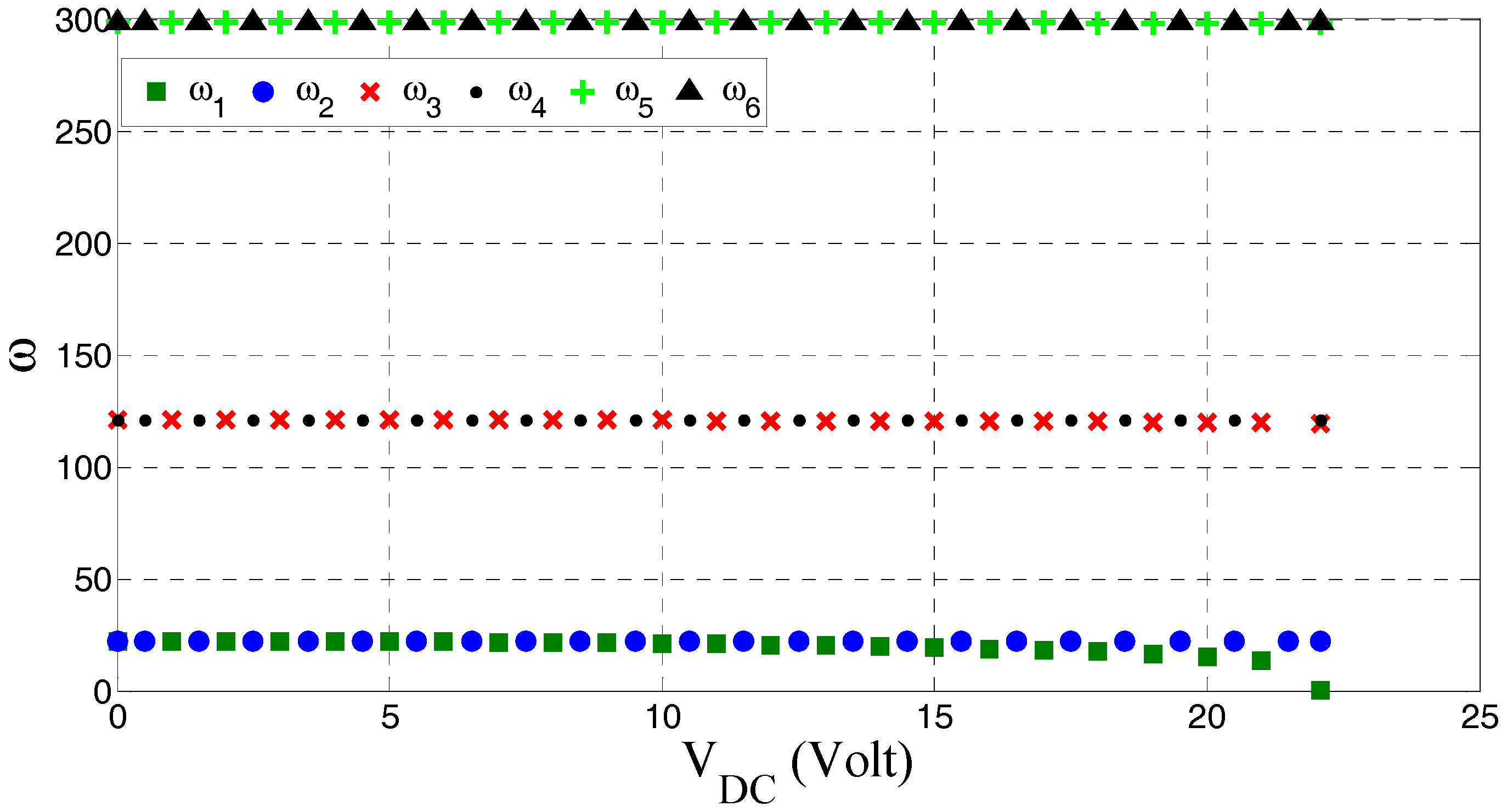
d2. The natural frequencies were obtained by using three symmetric modes and were displayed versus the applied voltage as shown in
Figure 8. The obtained results indicate that all of the higher-order natural frequencies are insensitive with the applied voltage, with the exception of the fundamental one (lower frequency). The fundamental natural frequency starts at its maximum position (when no electrical load is applied) and then decreases gradually with an increase in the applied voltage until it gets close to the pull-in voltage, at which point it drops sharply to zero. In addition, it can be noted that each odd natural frequency, when paired with the consecutive one are the same, except for the fundamental frequency, especially at higher applied DC voltages.
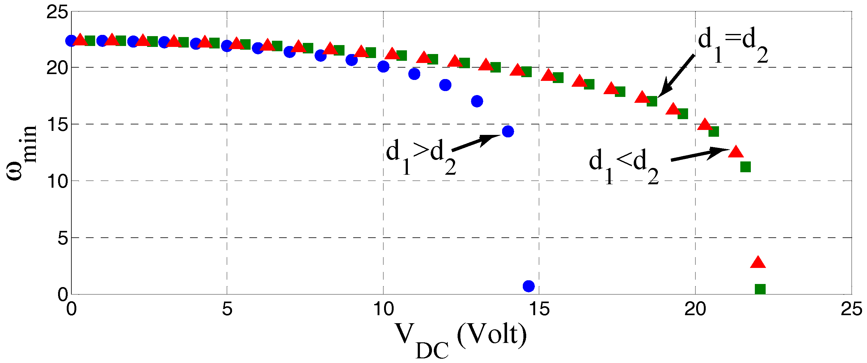
A comparison between the fundamental natural frequencies among the three cases considered in the static section is shown in
Figure 9. The results here seem to follow the static analysis outcomes, since in the case with the lowest pull-in voltage the fundamental frequency reaches zero first (when:
d1 >
d2). Moreover, the other two cases reach the pull-in voltage at about the same value (23 Volt) and accordingly their fundamental natural frequency drops to zero or close to it.
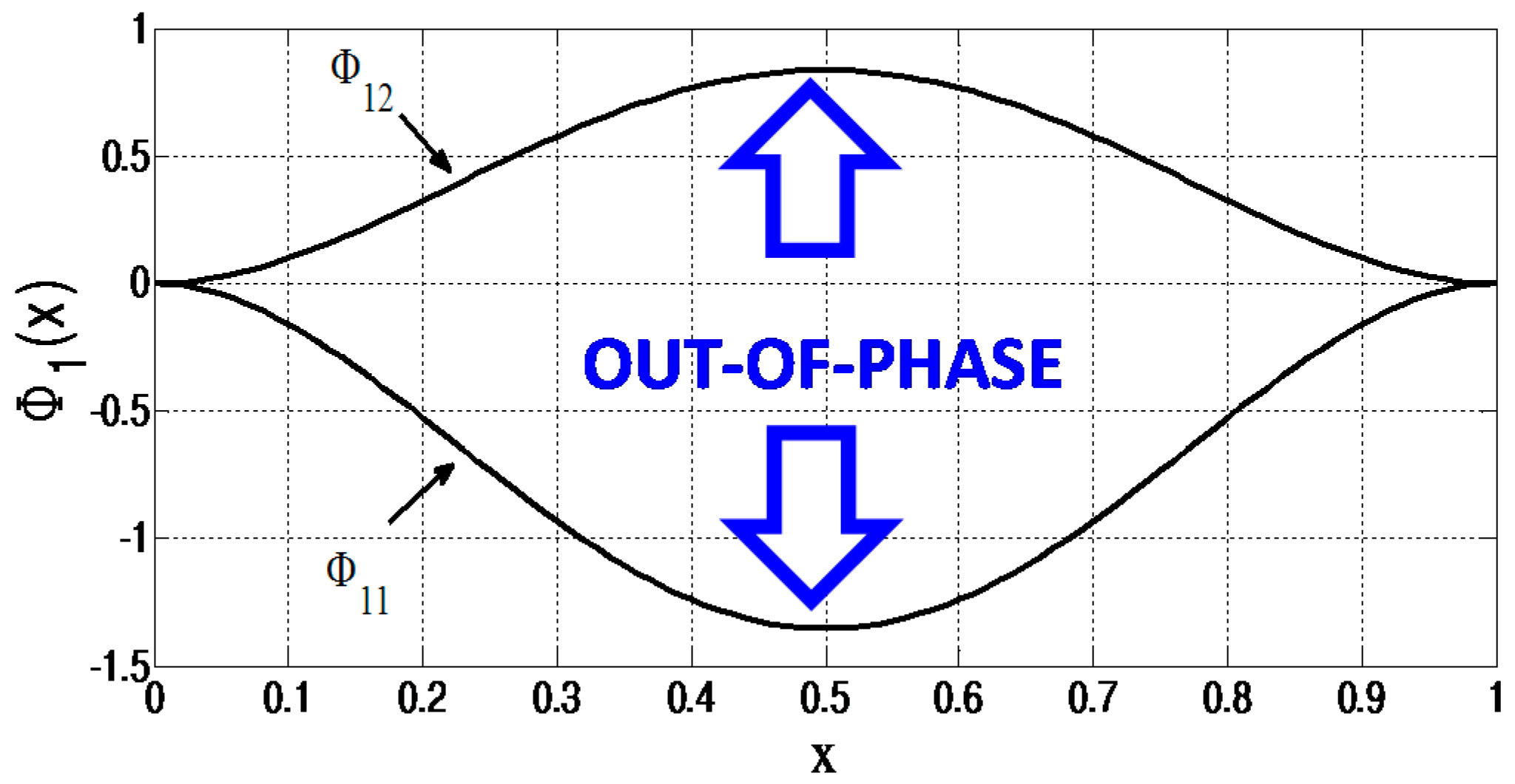
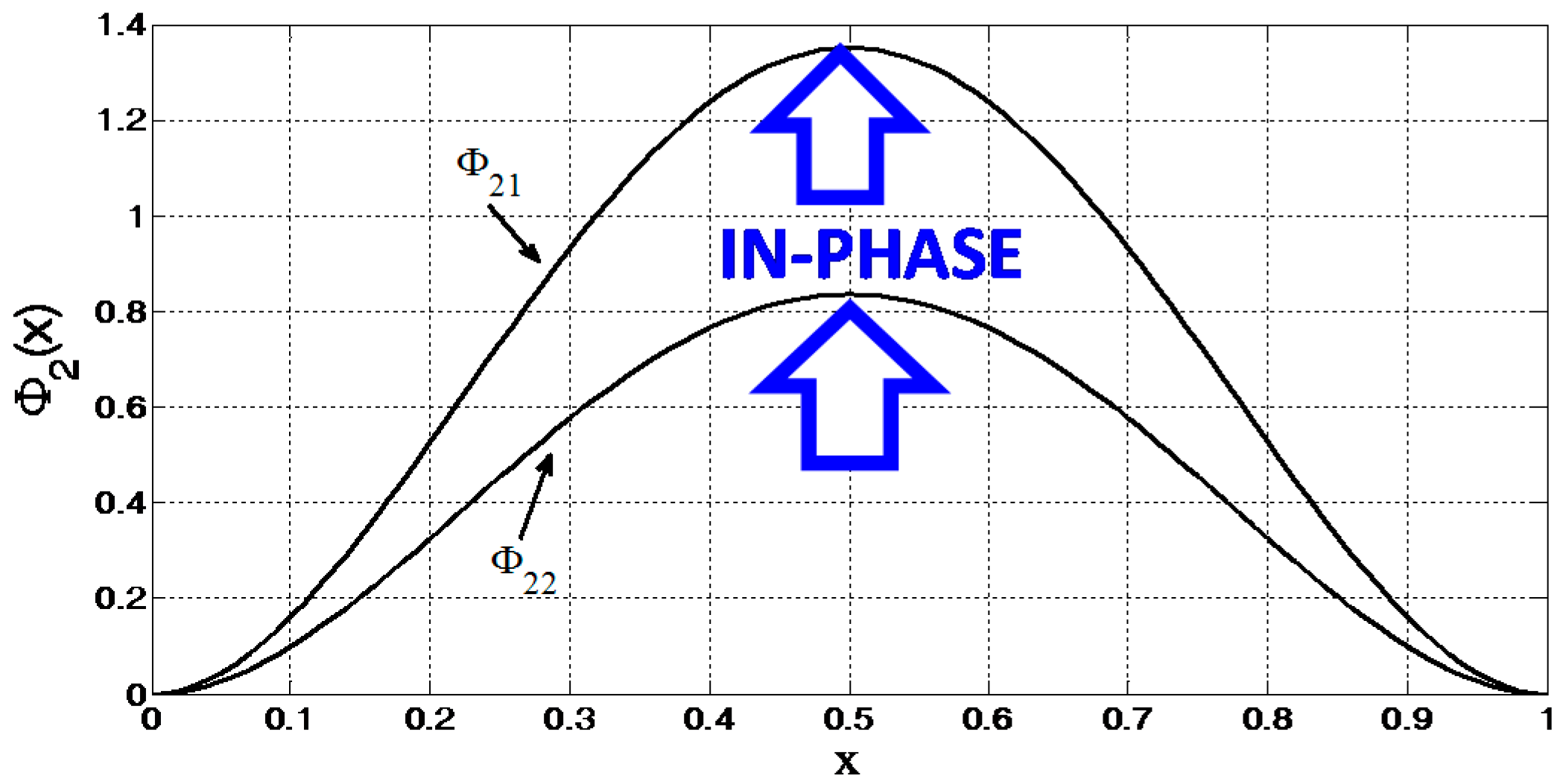
The first and second coupled mode shapes for the case of
d1 =
d2 at
VDC = 2 Volt are presented in
Figure 10 and
Figure 11, respectively. The results show that for the first mode shape
Ф1 the coupled modes (
Ф11 and
Ф12) are opposite to each other, sharing an out-of-phase motion. Conversely, for the second mode shape (
Ф2) the two coupled modes (
Ф21 and
Ф22) have almost the same magnitude as the first in an absolute value and both of them share an in-phase-motion.


