Article

The Proposal of Magnetic Suspension using Laterally Control Flux-Path Mechanism

Saitama University Graduate School of Sience and Engineering Control Engineering Laboratory, 338-8570 Saitama, Japan
*
Author to whom correspondence should be addressed.
Actuators 2017, 6(1), 11; https://doi.org/10.3390/act6010011
Submission received: 30 November 2016 / Revised: 15 March 2017 / Accepted: 17 March 2017 / Published: 21 March 2017
(This article belongs to the Special Issue Active Magnetic Bearing Actuators)

Abstract

:
A novel flux control magnetic suspension system that places control plates beside the magnetic source (permanent magnet) is proposed. In a conventional flux-path control magnetic suspension system, the control plates were inserted between the magnetic source and the suspended object (floator). In contrast, the control plates were placed beside the magnetic source in the proposed system. In such a configuration, the effective gap becomes larger than in the conventional system. Basic characteristics of the proposed magnetic suspension system were studied both numerically and experimentally. The numerical analyses show that the attractive force acting on the floator increases as the position of the lateral ring-shape control plate increases. The variation of the attractive force is sufficient for the stabilization of the suspension system. It is also shown that lateral force can be generated by dividing the plates into halves and moving them differentially. The predicted characteristics are confirmed experimentally in a fabricated apparatus with a three-axis force sensor and a gap adjustment mechanism.

1. Introduction

Magnetic suspension is a technology of suspending an object using magnetic force without any contact. Typical applications are the Maglev system [1] and magnetic bearing [2]. In addition, various applications are possible by taking advantage of such noncontact properties [3]. One of them is a wind tunnel system using magnetic suspension [4], in which an object is suspended by electromagnets across large gaps.
There are various methods of magnetic suspension that are classified according to ways of generating field force to support and material of the suspended body [1,2,3]. The most common method uses an electromagnet to suspend a ferromagnetic body (floator). The current of the electromagnet is controlled to produce a restoring force and damping. In several systems, direct field control using flux feedback has been applied [5,6,7,8]. One of the problems of this method is that a large current is necessary to achieve wide-gap suspension.
An effective approach to this problem is to use a permanent magnet as a magnetic source and a control flux-path mechanically [9]. In this approach, the amount of flux reaching the floator from the permanent magnet is controlled with a mechanism. There are several methods of controlling the flux path:
  • adjusting the reluctance in the magnetic circuit [9];
  • changing the flux path with a rotary actuator [10]; and
  • using a variable flux path mechanism [11].
In the first method, the actuator is required to generate force, canceling the gravity force acting on the floator so that a high-power actuator will be necessary to suspend a heavy floator. In the second method, the variation of the force is not expected to be large. This paper explores the third method.
In the original variable flux-path mechanism, ferromagnetic control plates are inserted into the gap between the magnetic source (permanent magnet) and the floator (ferromagnetic body). This is referred to as the flux-interrupted type. The distance between the plates is controlled with a pair of actuators [11] or a single actuator [12]. Because the flux from the permanent magnet to the floator is a function of the distance, the attractive force acting on the floator can be controlled with the actuator(s). However, the suspension force produced in the actual system was not so large [13]. One of the reasons is that the flux flowing into the control plates and the leakage flux are rather large and resultantly the flux reaching the floator is small. To overcome this problem, another type has been proposed in which ferromagnetic control plates are replaced by plates made of permanent magnet. This is referred to as the flux-concentrated type. The flux from the magnetic source to the floator is concentrated by the control plates so that the attractive force increases [14].
In both types, however, control plates are placed between the magnetic source and the floator. This leads to the reduction of the effective gap, which is defined as the gap between the floator and control plates instead of the magnetic source, which is an obstacle to achieving wide-gap suspension. In this paper, a new configuration of variable flux-path control mechanism, which is characterized by placing control plates beside a magnetic source, is proposed. This configuration is referred to as a laterally controlled type.

2. Principles

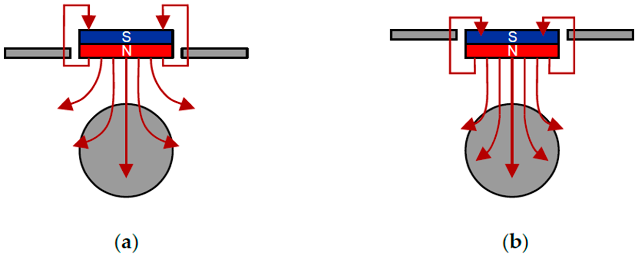
2.1. The Flux-Interrupted Type

In the flux-path control magnetic suspension system, the attractive force of the permanent magnet is controlled by varying the amount of flux that reaches the suspended object (floator). Figure 1a shows a schematic illustration of the flux-path control magnetic suspension using flux-path interrupted plates. In this system, a pair of control plates is inserted between the permanent magnet and the floator. As the distance between the control plates becomes wider, the amount of the flux reaching the floator increases and the attractive force acting on the floator becomes larger. In contrast, as the distance between the control plates becomes narrower, the attractive force becomes smaller. Based on this principle, the attractive force is controlled by adjusting the distance between the control plates.

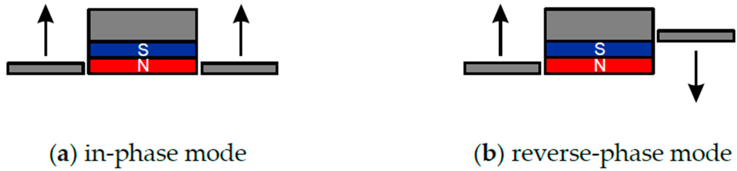
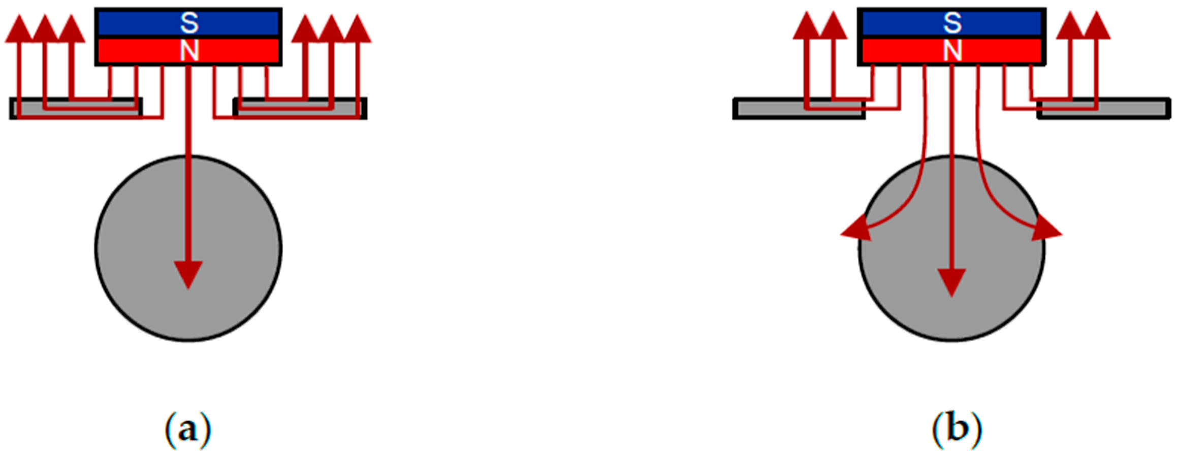
2.2. The Laterally Controlled Type

Figure 1b shows a schematic illustration of the flux-path control magnetic suspension using control plates placed in the lateral of the magnetic source (permanent magnet). In this system, the attractive force is adjusted by moving the control plates in the vertical direction beside the permanent magnet. Thus, the effective gap is wider than that of the flux-interrupted type. Figure 2 shows the principle of adjustment of the attractive force. When the control plates are placed at the lowest position where the bottom of the control plates is aligned with that of the permanent magnet, more flux flows into the control plates, and the attractive force becomes smaller. When the control plates are placed at the highest position, where the top of the control plates is aligned with that of the permanent magnet, the attractive force becomes larger because the control plates work as yoke.
This configuration is suitable for achieving wide-gap levitation as mentioned above. One of the target applications is, therefore, a wind tunnel system in which a wide gap is required to avoid adverse effects caused by the wall of the tunnel.

3. Magnetic Field Analysis

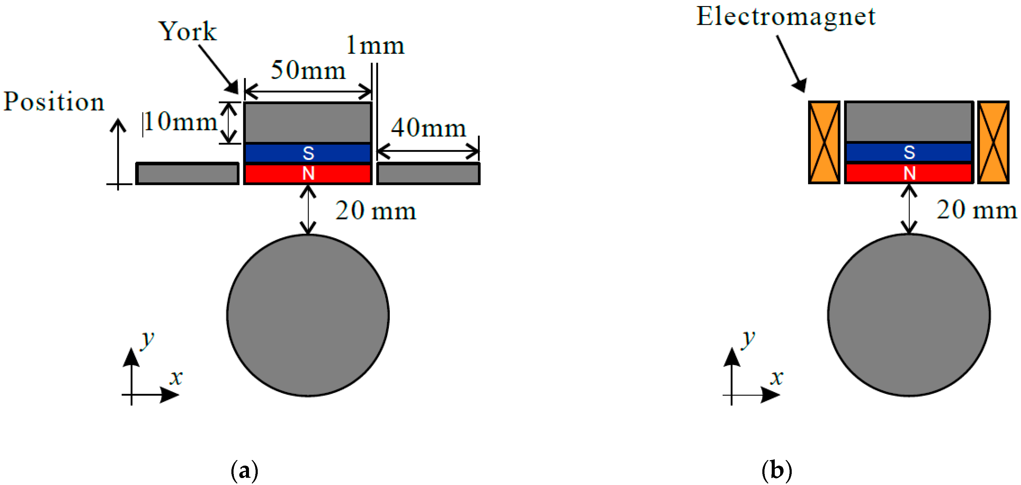
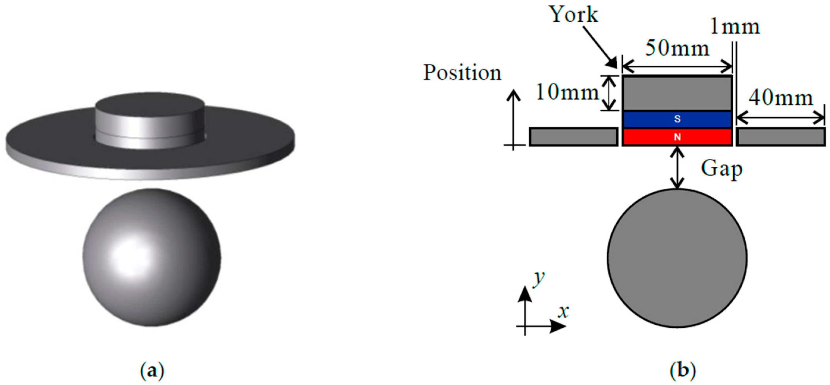
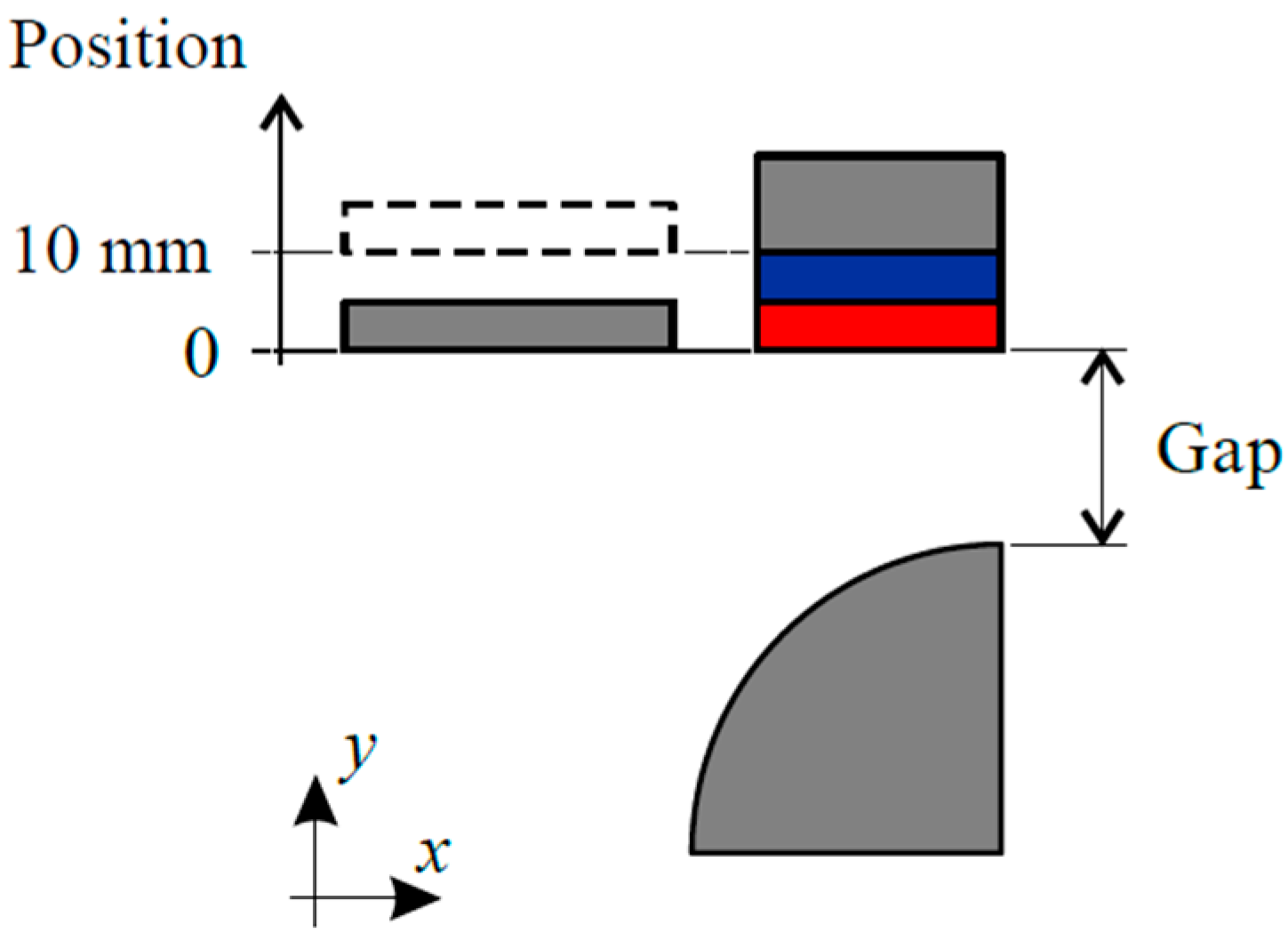
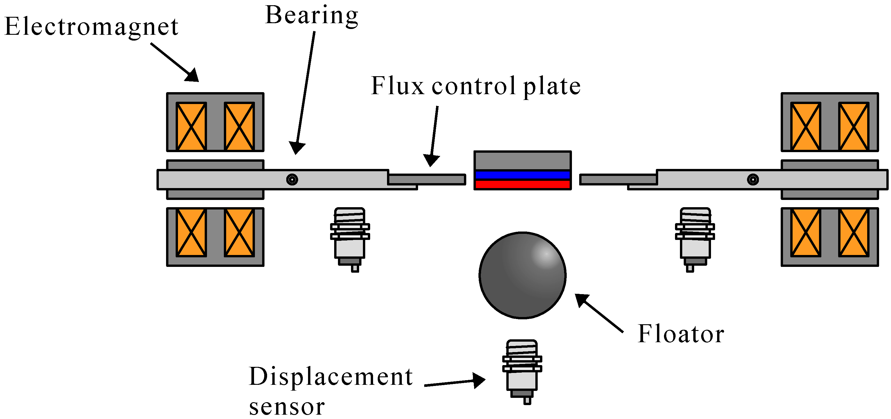
3.1. Analytical Model

Figure 3 shows an analysis model. In such a system, flux leakage is rather large because the magnetic circuits are not closed, making the analytical study on the magnetic fields so complex that we used a Finite Element Modeling (FEM) program JMAG in the following analyses. The target model is composed of a cylindrical magnetic source, a ring-shaped control plate, and a spherical floator. The control plate is made of steel. The outer and inner diameters are 132 mm and 52 mm, respectively, and the thickness is 5 mm. The magnetic source is a permanent magnet with a diameter of 50 mm and a thickness of 10 mm. The floator is an iron ball with a diameter of 63.5 mm. The yoke is attached on the permanent magnet to increase the attractive force acting on the floator. The mesh size in the FEM analysis is 2 mm.

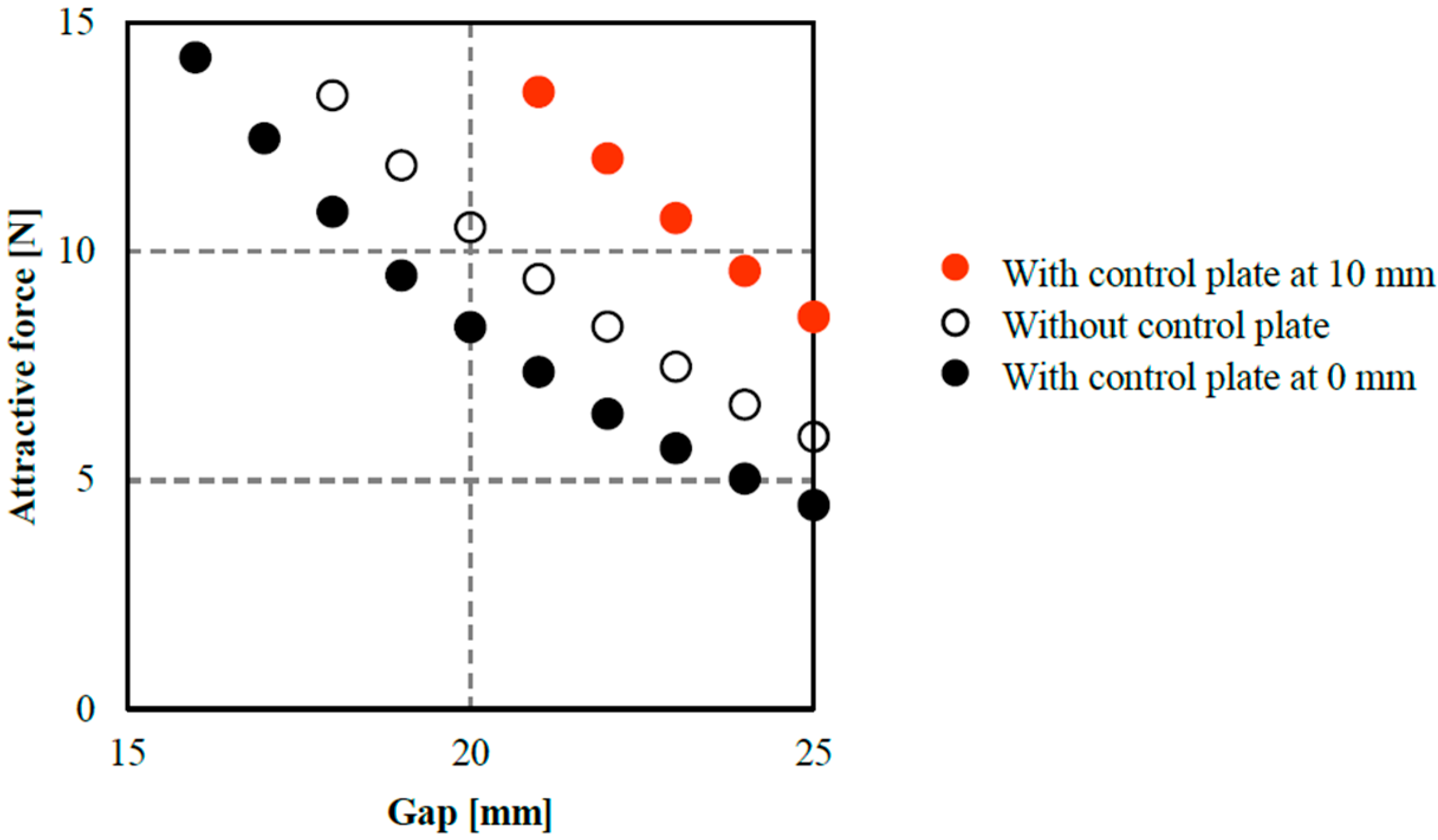
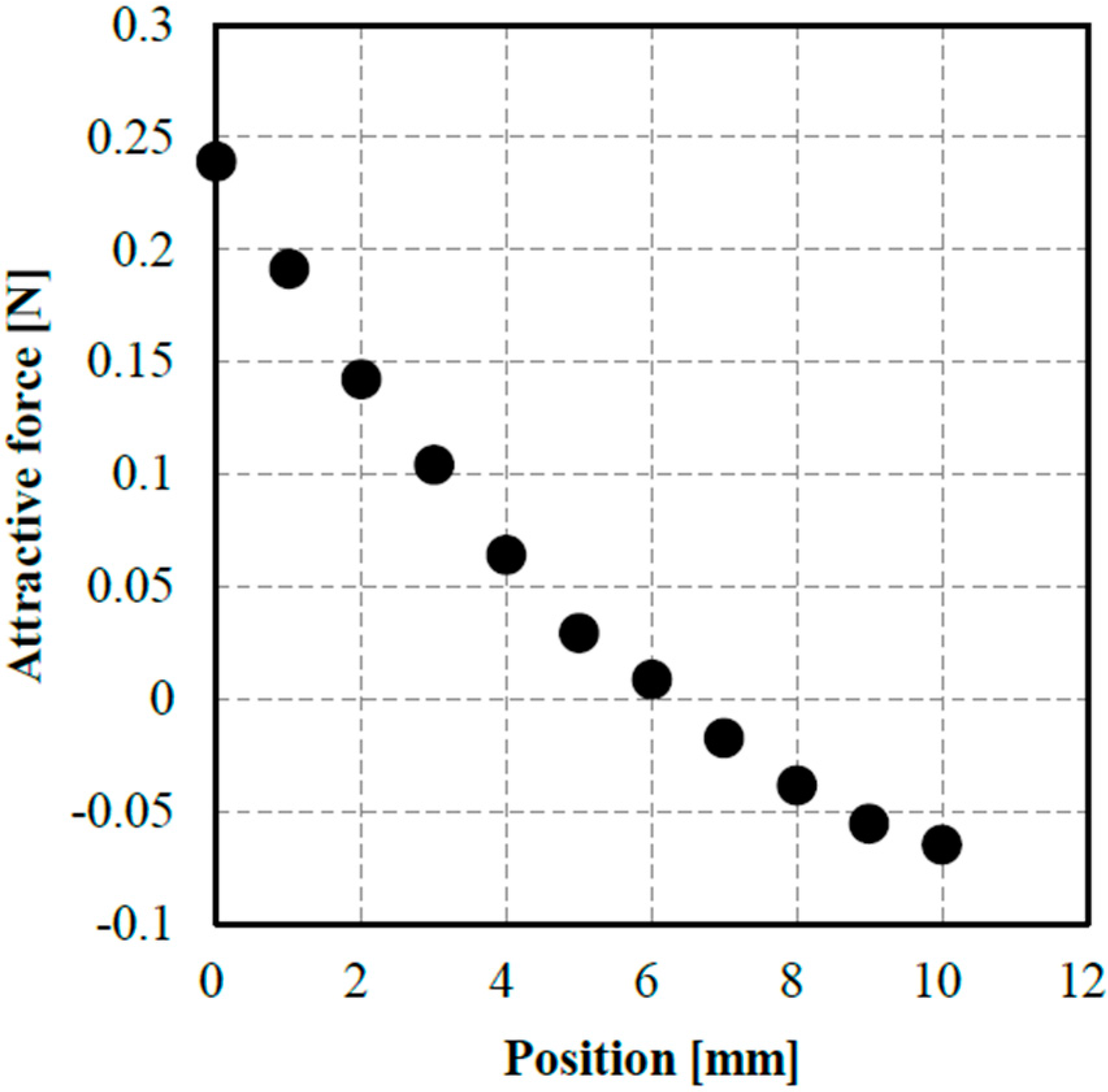
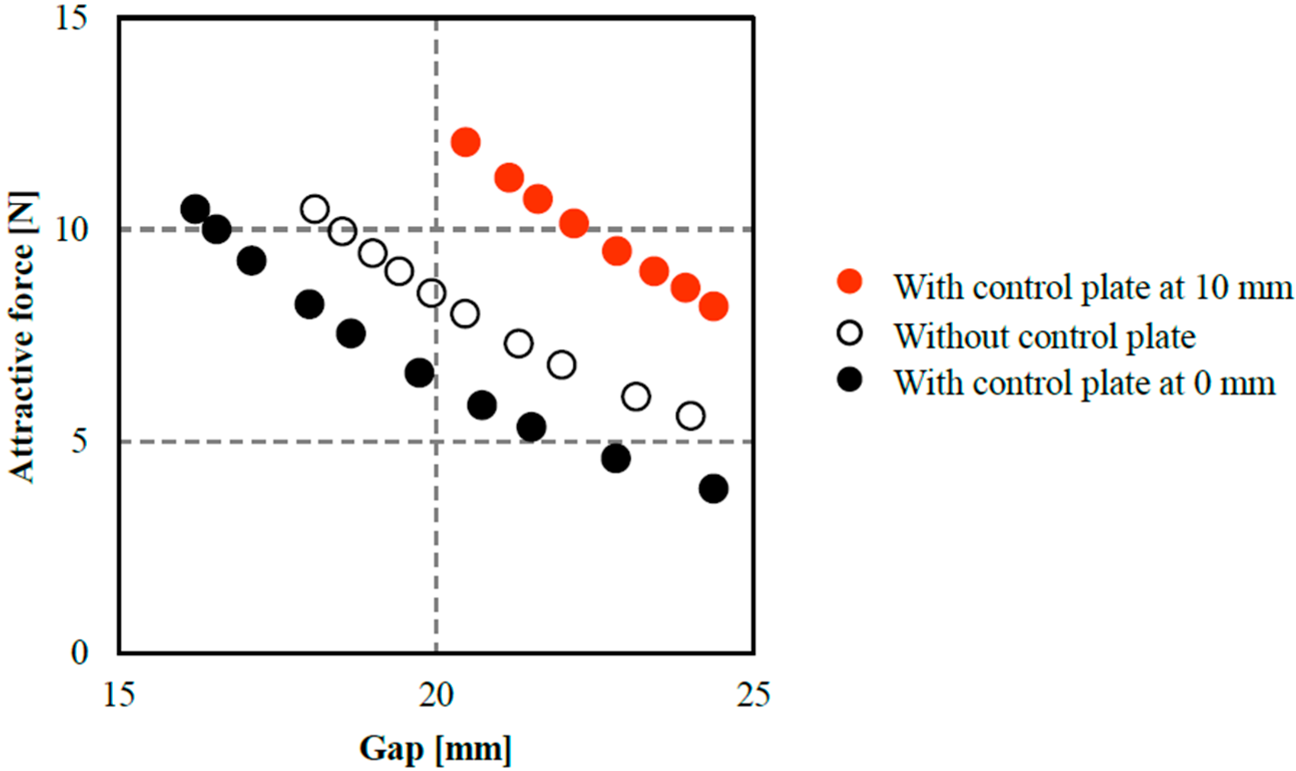
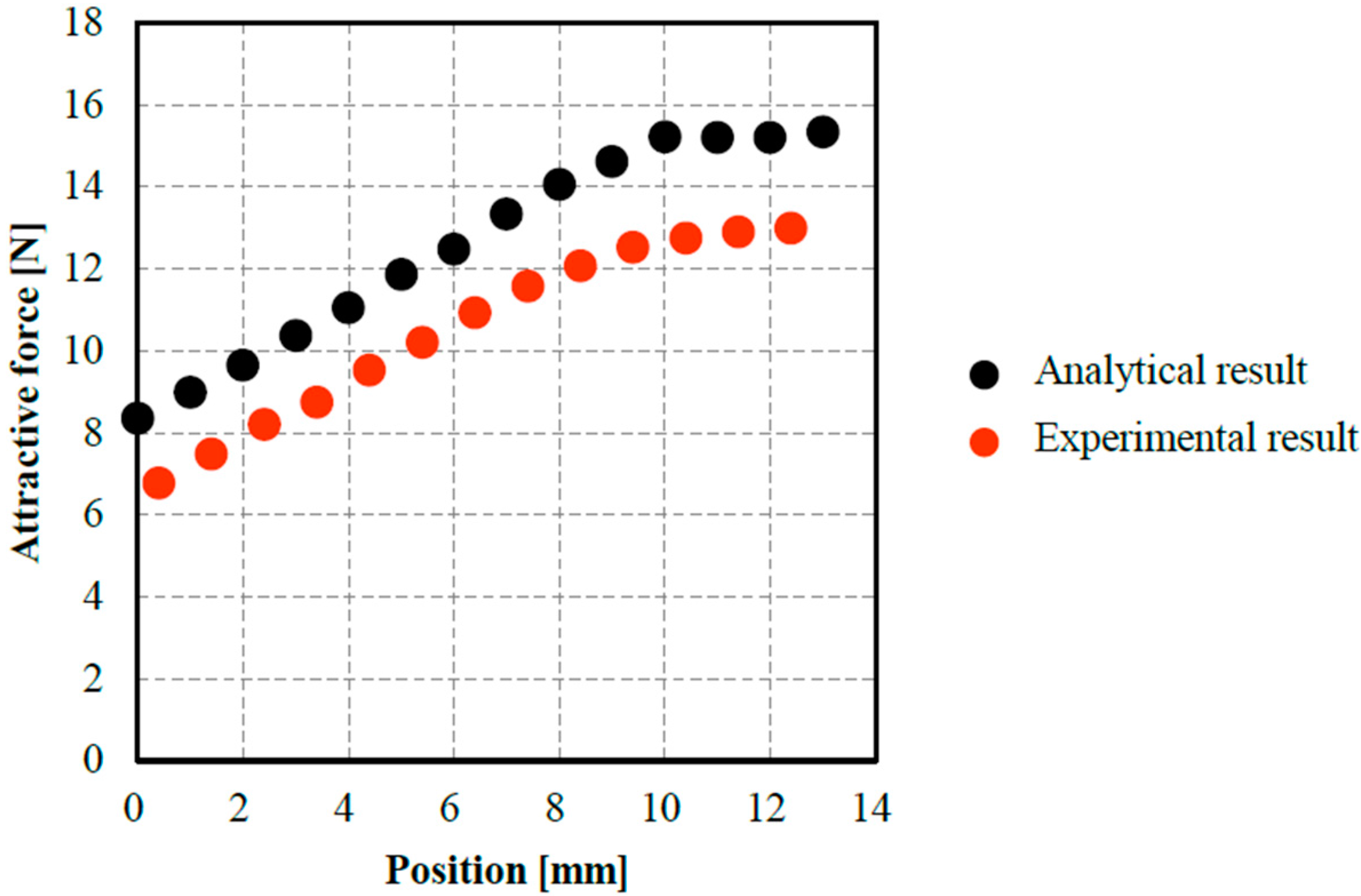
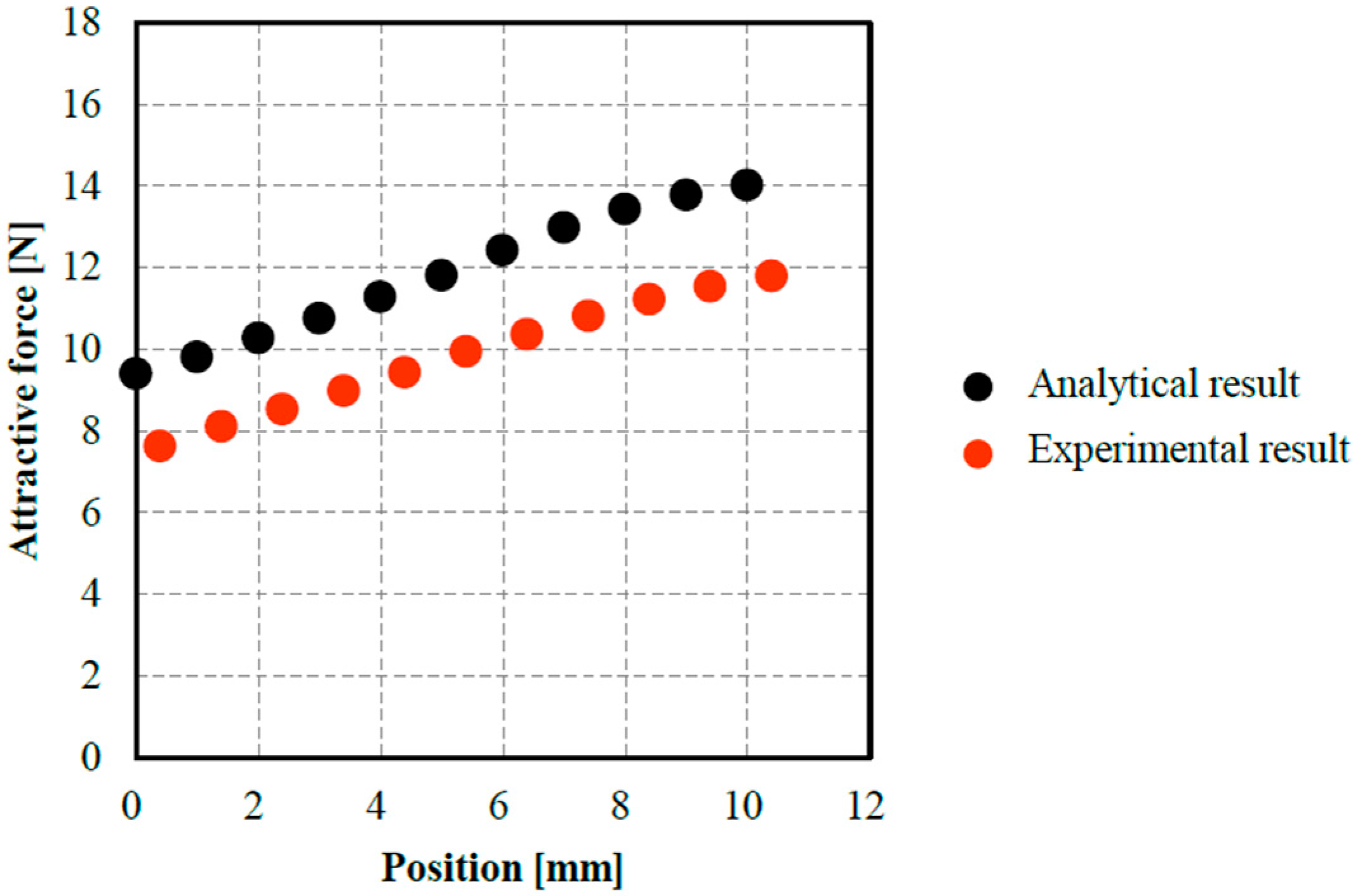
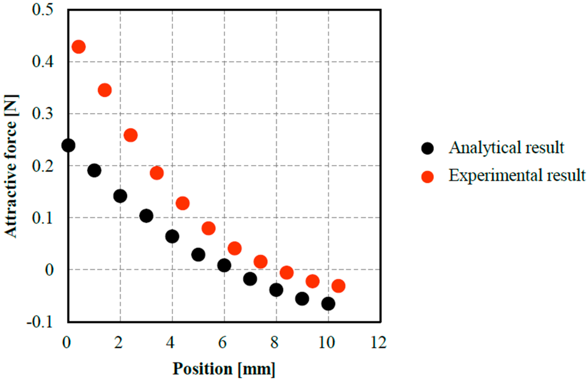
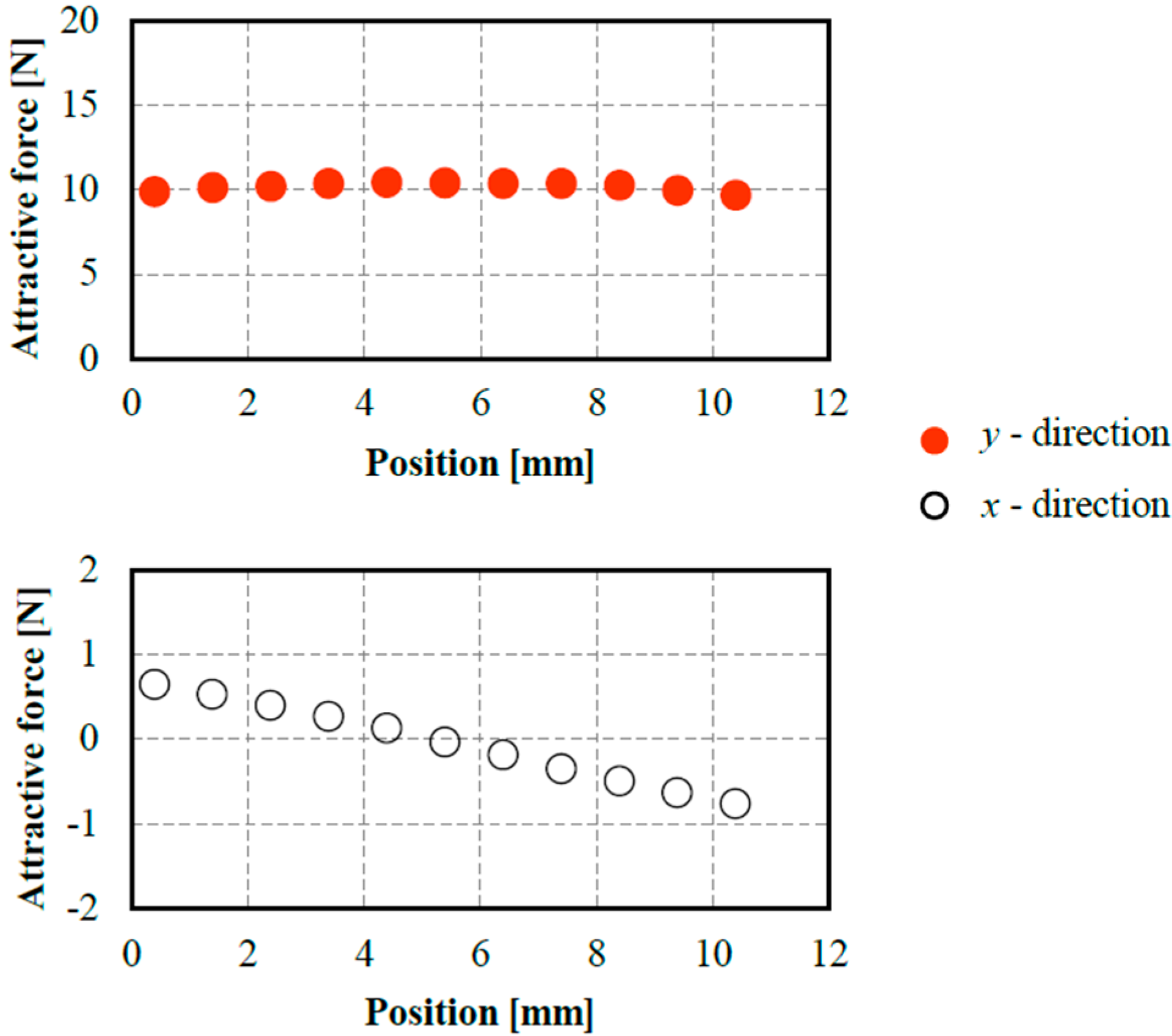
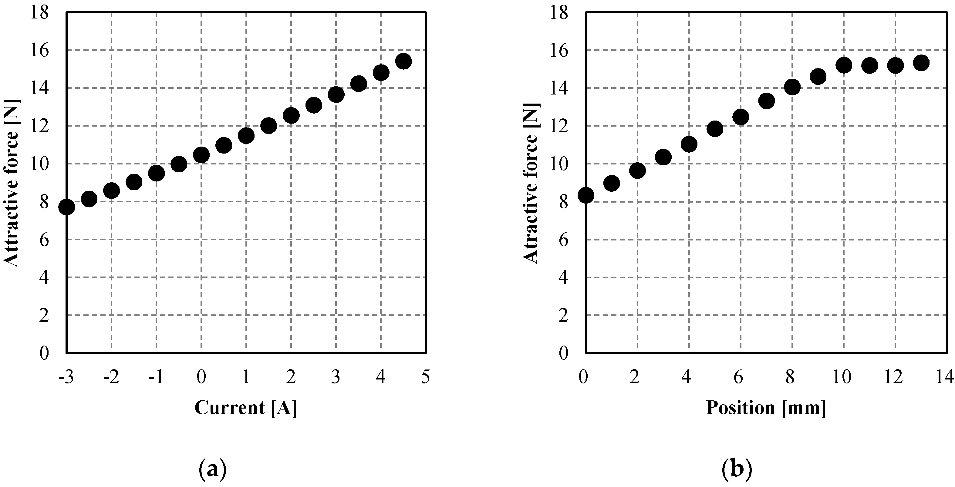
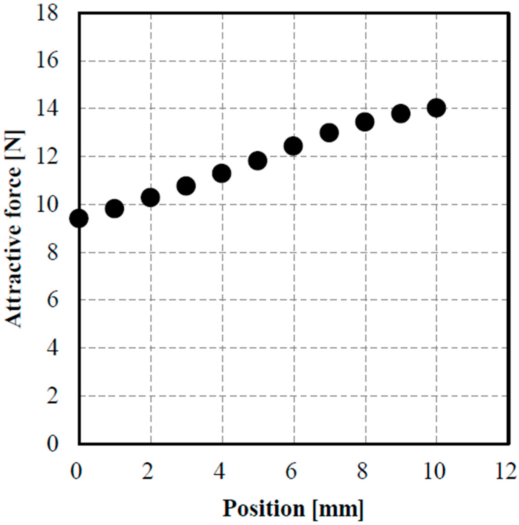
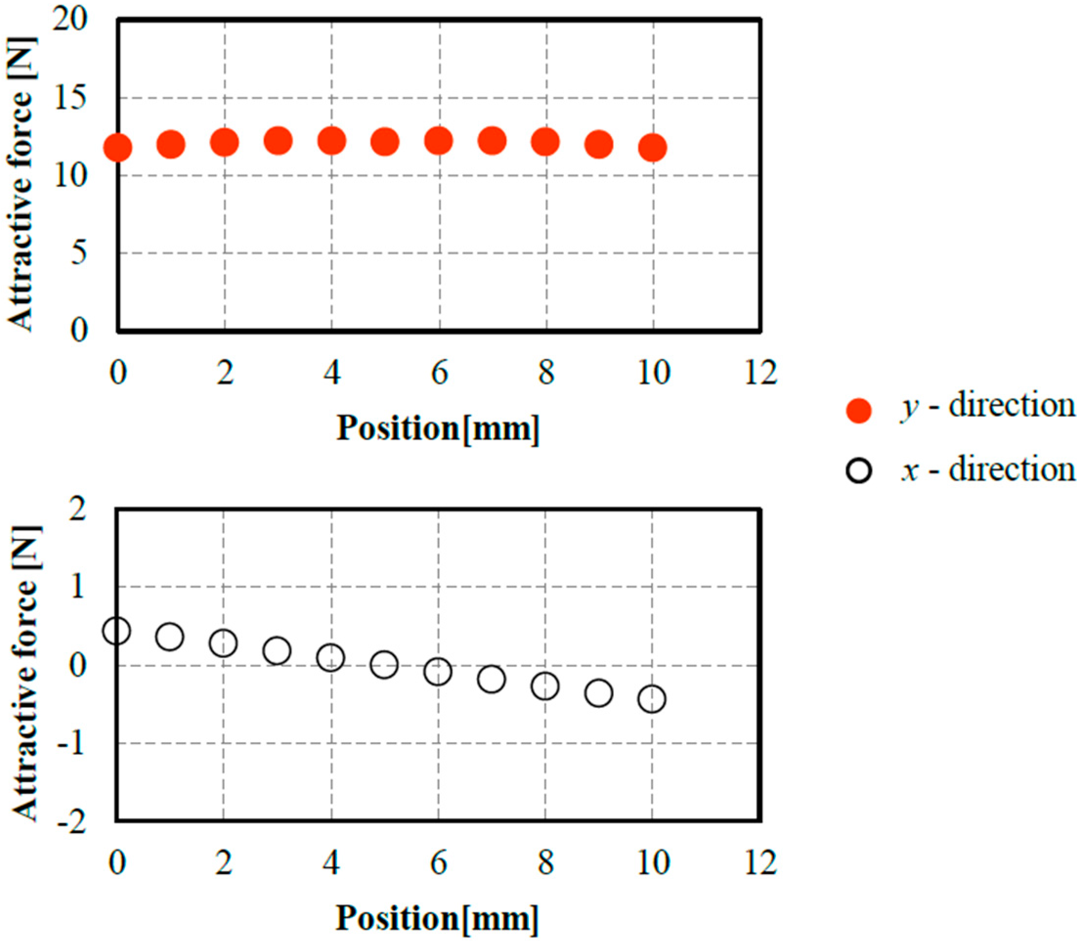
3.2. Attractive Force Characteristics

The gap is defined as the distance between the bottom of the permanent magnet and the top of the floator. The control plate is placed at the position of 0 mm (the lowest position) or 10 mm. Figure 4 illustrates each position of the control plate. Figure 5 shows the gap-force characteristics obtained via numerical analysis. Compared to the attractive force without the control plate, the attractive force is smaller when the control plate is at the lowest position, and is larger at the position of 10 mm.
Then, the gap is fixed to be 20 mm. The control plate is placed at the lowest position and moves upward to the position of 10 mm. The attractive force at each position is shown in Figure 6. The variation of the attractive force is 0.7 N/mm. In addition, the attractive force is saturated when the position is higher than 10 mm.
In Appendix A, an analytical result of such attractive force characteristics is shown for comparison with a conventional suspension system with an electromagnet.
Next, to achieve the motion control of the floator in the lateral direction, the control plate is divided into halves symmetrically at the y-axis. The left half control plate (left control plate) is placed at the lowest position and moved upward. The attractive force in the y-direction (normal force) is shown in Figure 7. The variation of the attractive force is 0.4 Nm/mm and smaller than that obtained by the annular plate. The attractive force in the x-direction (lateral force) is shown in Figure 8. The lateral force is generated by moving one of the half plates.
These results indicate the possibility of two-degree-of-freedom-of-motion control by moving the halves individually. Figure 9 shows two modes of control. The normal force is adjusted by moving control plates in the in-phase mode (a). The lateral force is adjusted by moving control plates in the reverse-phase mode (b). Figure 10 shows the normal and lateral forces in the reverse-phase mode. The normal force is 12 N and almost constant. In contrast, the lateral force varies linearly. The variation of the lateral force is 0.1 N/mm.

4. Experiment

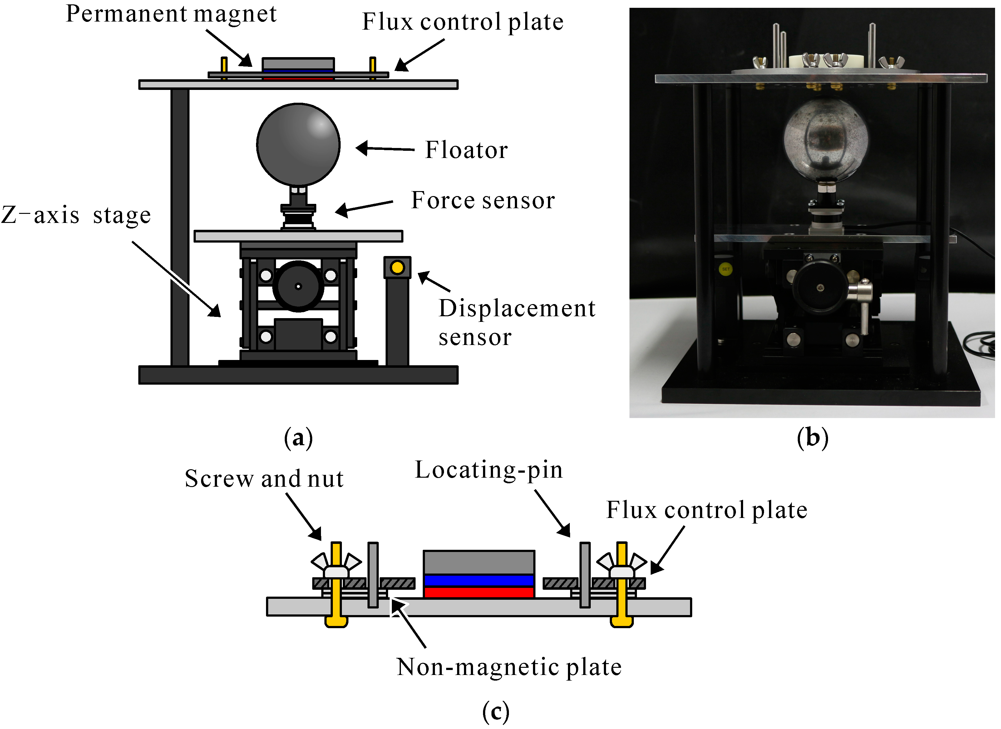
Experimental Apparatus

An experimental apparatus was fabricated to measure the attractive forces under the same conditions assumed in the analysis. Figure 11 shows schematic illustrations and a photograph of the experimental apparatus. An annular control plate is placed to align its center axis with that of a cylinder-shape permanent magnet. The height of the plate is adjusted by inserting a non-magnetic plate whose thickness is known. The lateral position of the plate is adjusted by locating-pins and screws as shown by Figure 11c. The position of a floator is detected by an eddy-current displacement sensor. The attractive forces are measured using a 3-axis force sensor on which the floator is fixed. The floator is made of SUJ-2 with a diameter of 63.5 mm and a mass of 1 kg. The permanent magnet is made of neodymium with a surface magnetic flux density of 380 mT, a diameter of 50 mm, and a thickness of 10 mm.
The gap-force characteristics are measured when the control plate is placed at the lowest position and the position of 10 mm. The result is shown in Figure 12. When the control plate is placed at the lowest position, the attractive force is smaller than that without the control plate. When the control plate is placed at the 10 mm position, the attractive force is larger than that without the control plate.
Then, the gap between the permanent magnet and the floator is fixed to 20 mm. The control plate is placed at the lowest position and moved upward. The force at each position is shown in Figure 13. The variation of the attractive force is 0.7 N/mm. In addition, the attractive force is saturated when the position is higher than 10 mm. These experimental results have the same tendency as the analytical results. However, the attractive force predicted by the FEM analysis is larger than the measured force. One of the reasons is that the target system has a rather large leakage flux. In addition, the parameters such as the permeance of iron are set to be nominal in the FEM analysis and are not measured. These parameters may have caused the differences.
Next, experiments on the control plate halves are carried out. The left half control plate is placed at the lowest position and moved upward. The normal force is shown in Figure 14. The variation of the attractive force is 0.4 N/mm and smaller than that obtained by using the annular plate. The lateral force is shown in Figure 15. The lateral force is generated by moving one of the half plates.
Then, the left control plate is placed at the lowest position, and the right control plate is placed at the position of 10 mm. The left control plate is moved upward. The right control plate is moved downward. The normal and lateral forces are shown in Figure 16. The normal force is 10 N and almost constant. In contrast, the lateral force varies linearly. The variation of the lateral force is 0.15 N/mm.
The normal force is adjusted by moving the control plate in the vertical direction. The lateral force is adjusted by in accordance with the difference between the height of the left plate and that of the right plate. Thus, it is possible to realize 2-axis magnetic suspension with two control plates. These results indicate the possibility of 3-degree-of-freedom-of-motion control with three control plates moved individually [15].

5. Design of Flux-Path Control Mechanism

To achieve stable suspension, the flux control plate must be moved dynamically according to the motion of the floator. Figure 17 shows a schematic illustration of a suspension system with a pair of mechanisms achieving such motion control of the flux control plates. In this mechanism, a ferromagnetic control plate is fixed to one end of a lever made of non-magnetic material. The lever is suspended by a ball bearing to rotate about a horizontal axis. Such a seesaw-type structure has an advantage of very high stiffness in the direction toward the permanent magnet. A pair of electromagnets is placed at each end of the lever to face each other across the lever. They control the rotation motion of the lever. The motion of the lever at the electromagnets is mechanically amplified about five times at the other end of the control plate in the designed mechanism. In the analysis, the control plate moves from the positon of 0 mm to the position of 10 mm. To achieve this stroke, the nominal gap between the lever and each electromagnet is set to 2 mm.
In the flux-concentrated type magnetic suspension system [16], a similar flux-path control mechanism was used to achieve stable suspension. The bandwidth of the mechanism was 20 Hz approximately. The newly designed mechanism for lateral flux-path control can have a bandwidth of the same order because of the similarity in structure. Therefore, stable suspension can be achieved using this mechanism.

6. Conclusions

A novel flux-path control magnetic suspension system using a laterally controlled flux-path mechanism was proposed to increase the effective gap. In the proposed system, control plates are placed in the lateral of the magnetic source. The attractive force acting on the floator was studied both analytically and experimentally. In addition, the variation of the attractive forces in the normal and lateral directions is generated by moving control plates in in-phase and reverse-phase modes. This shows the possibility of a multi-axis magnetic suspension system.

Author Contributions

Ishibashi, N. and Mizuno, T. wrote the paper. Ishino, Y. and Yamaguchi, D. contributed the design of the mechanisms; Hara, M. and Takasaki, M. contributed the analyses of the data; Yamada, K. found the location of the control plates and contributed the numerical analyses.

Conflicts of Interest

The authors declare no conflict of interest. The founding sponsors had no role in the design of the study; in the collection, analyses, or interpretation of data; in the writing of the manuscript, and in the decision to publish the results.

Appendix A

The flux-path control magnetic suspension using control plates is compared with a conventional magnetic suspension using DC electromagnet. The proposed system is the same as the system treated in Section 3.1. The conventional system using an electromagnet is composed of the cylindrical magnetic source with ferromagnetic yoke, a coil, and the spherical floator (Figure A1). The number of turns of the coil is assumed to be 500. The coil is placed to align its center axis with that of the cylinder-shape permanent magnet. The gap is fixed to be 20 mm. The control plate is placed at the lowest position and moved upward to the position of 10 mm. The attractive force at each position is shown in Figure A2a (Figure 6). The attractive force varies from 8 N to 15 N. Then, the current-force characteristics of the suspension system (b) are analyzed. The result is shown in Figure A2b. In order to obtain the same variation of the attractive force (7 N), it is necessary to vary the current more than 7 A, that is, the necessary magnetomotive force is 3500 AT, which is rather large. This result suggests that the flux-path control magnetic suspension using the control plates is suitable for wide-gap suspension with low-energy consumption.
Figure A1. Analysis model and parameters: (a) analysis model using control plate; (b) analysis model using Electromagnet.
Actuators 06 00011 g018
Figure A2. Analytical result: (a) attractive force when the control plate is moved in the vertical direction; (b) attractive force when the current of electromagnet is varied.
Actuators 06 00011 g019

References

  1. Jayawant, B.V. Electromagnetic Levitation and Suspension Techniques; Edward Arnold Publishers Limited: London, UK, 1981; pp. 1–17. [Google Scholar]
  2. Schweitzer, G.; Maslen, E.H. (Eds.) Magnetic Bearings; Springer: Berlin/Heidelberg, Germany, 2009; pp. 1–68.
  3. The Magnetic Levitation Technical Committee of the Institute of Electrical Engineers of Japan (IEE Japan) (Ed.) Magnetic Suspension Technology; Corona Publishing Co., Ltd.: Tokyo, Japan, 1993; pp. 8–13.
  4. Mizuno, T.; Sakai, Y.; Ishino, Y.; Takasaki, M. Fabrication of a New Wind Tunnel for Spinning Body Using Magnetic Suspension. In Proceedings of the 13th International Symposium on Magnetic Bearings (ISMB13), Arlington, VA, USA, 6–9 August 2012.
  5. Bahr, F.; Monch, I.; Ernst, D.; Zerna, T.; Schmidt, O.G.; Hofmann, W. Direct Field Control of AMBs Using Flux Feedback Based on Integrable Hall Sensors. In Proceedings of the 15th International Symposium on Magnetic Bearings (ISMB15), Kitakyushu, Japan, 3–6 August 2016.
  6. Bahr, F.; Melzer, M.; Karnaushenko, D.; Makarov, D.; Bermudez, G.C.; Schmidt, O.G.; Hofmann, W. Permanent Magnet Bias AMB Using Integrated Hall Sensor Based Air Gap Flux Density Feedback. In Proceedings of the 1st Brazilian Workshop on Magnetic Bearings, Rio de Janeiro, Brazil, 25–26 October 2013.
  7. Mystkowski, A.; Pawluszewicz, E. Remarks on Some Robust Nonlinear Observer and State-Feedback Zero-Bias Control of AMB. In Proceedings of the IEEE 16th International Carpathian Control Conference, Szilvásvárad, Hungary, 27–30 May 2015; pp. 328–333.
  8. Jastrzebski, R.P.; Smirnov, A.; Mystkowski, A.; Pyrhönen, O. Cascaded Position-Flux Controller for AMB System Operating at Zero Bias. Energies 2014, 7, 3561–3575. [Google Scholar] [CrossRef]
  9. Higuchi, T.; Oka, K. Reluctance Control Magnetic Suspension System—Suspension System with Permanent Magnet and Linear Actuator. Electr. Eng. Jpn. 1993, 114, 115–123. [Google Scholar] [CrossRef]
  10. Oka, K.; Fujiwara, Y.; Cui, T.; Mihara, T. Mag-Lev system Using Permanent Magnet and Rotary Actuator. In Proceedings of the 47th Japan Joint Automatic Control Conference, Chiba, Japan, 26–27 November 2004; p. 316. (In Japanese)
  11. Mizuno, T.; Hoshino, H.; Ishino, Y.; Takasaki, M. Proposal and Basic Experimental Study of Flux Path Control Magnetic Suspension. J. Jpn. Soc. Appl. Electromagn. Mech. 2006, 14, 346–352. (In Japanese) [Google Scholar]
  12. Mizuno, T.; Sakai Y.; Takasaki, M.; Ishino, Y. Development of Flux-Path Control Module with a Single Actuator. J. Jpn. Soc. Appl. Electromagn. Mech. 2012, 20, 94–299. (In Japanese) [Google Scholar]
  13. Furutachi, M.; Inaba, S.; Ishino, Y.; Takasaki, M.; Mizuno, T. Three-Dimensional Force Measurement and Control of a Flux-Path Control Magnetic Suspension. J. Syst. Des. Dyn. 2008, 2, 1239–1249. (In Japanese) [Google Scholar] [CrossRef]
  14. Mizuno, T.; Yoneno, Y.; Ishino, Y.; Takasaki, M. Proposal of Flux-Path Control Magnetic Suspension Using Flux Concentration. In Proceedings of the 1st Brazilian Workshop on Magnetic Bearings, Rio de Janeiro, Brazil, 25–26 October 2013.
  15. Mizuno, T.; Hirai, Y.; Ishino, Y.; Takasaki, M. Flux-Path Control Magnetic Suspension System Using Voice Coil Motors. J. Syst. Des. Dyn. 2007, 1, 147–158. [Google Scholar] [CrossRef]
  16. Hasan, S.; Mizuno, T.; Takasaki, M.; Ishino, Y.; Hara, M.; Yamaguchi, D. Design and Fabrication of an Enlarged Wind Tunnel System for Spinning Body Using Magnetic Suspension. J. Jpn. Soc. Appl. Electromagn. Mech. 2016, 24, 264–270. [Google Scholar] [CrossRef]
Figure 1. A flux-path control magnetic suspension system using flux-interrupting plates: (a) a small attractive force when the distance between the control plates is small; (b) a large attractive force when the distance is large.
Actuators 06 00011 g001
Figure 2. A flux-path control magnetic suspension system using control plates in the lateral of the magnetic source: (a) a small attractive force when the control plates are lowered; (b) a large attractive force when the control plates are raised.
Actuators 06 00011 g002
Figure 3. Analysis model and parameters: (a) analysis model; (b) parameters of magnetic suspension mechanism.
Actuators 06 00011 g003
Figure 4. Position of the control plate.
Actuators 06 00011 g004
Figure 5. Analyzed gap-force characteristics for various positions of the control plate.
Actuators 06 00011 g005
Figure 6. Attractive force when the control plate is moved in the vertical direction.
Actuators 06 00011 g006
Figure 7. Attractive force in the y-direction when half of a control plate is moved in the vertical direction.
Actuators 06 00011 g007
Figure 8. Attractive force in the x-direction when half of a control plate is moved in the vertical direction.
Actuators 06 00011 g008
Figure 9. Modes of moving the control plates: (a) moving control plates in the in-phase mode; (b) moving control plates in the reverse-phase.
Actuators 06 00011 g009
Figure 10. Attractive force when two control plate halves are moved in the vertical direction in the reverse-phase.
Actuators 06 00011 g010
Figure 11. Instrument for force measurement: (a) schematic of apparatus for force measurement; (b) photograph of apparatus for force measurement; (c) schematic of mechanism to adjust the lateral position of the control plate in the apparatus.
Actuators 06 00011 g011
Figure 12. Measured gap-force characteristics for various height of control plate.
Actuators 06 00011 g012
Figure 13. Attractive force when the control plate is moved in the vertical direction.
Actuators 06 00011 g013
Figure 14. Attractive force in the y-direction when half of a control plate is moved in the vertical direction.
Actuators 06 00011 g014
Figure 15. Attractive force in the x-direction when half of a control plate is moved in the vertical direction.
Actuators 06 00011 g015
Figure 16. Attractive force when two control plate halves are moved in the vertical direction in the reverse-phase.
Actuators 06 00011 g016
Figure 17. Schematic illustration of suspension system.
Actuators 06 00011 g017

