Modeling and Realization of a Bearingless Flux-Switching Slice Motor


1
Institute of Electrical Drives and Power Electronics, Johannes Kepler University, Altenberger Str. 69, 4040 Linz , Austria
2
LCM GmbH, Altenberger Str. 69, 4040 Linz , Austria
*
Author to whom correspondence should be addressed.
Actuators 2017, 6(2), 12; https://doi.org/10.3390/act6020012
Submission received: 20 December 2016
/
Revised: 10 March 2017
/
Accepted: 22 March 2017
/
Published: 27 March 2017
(This article belongs to the Special Issue Active Magnetic Bearing Actuators)
Abstract
:This work introduces a novel bearingless slice motor design: the bearingless flux-switching slice motor. In contrast to state-of-the-art bearingless slice motors, the rotor in this new design does not include any permanent rotor magnets. This offers advantages for disposable devices, such as those used in the medical industry, and extends the range of bearingless slice motors toward high-temperature applications. In this study, our focus is on the analytical modeling of the suspension force torque generation of a single coil and the bearingless motor. We assessed motor performance in relation to motor topology by applying performance factors. A prototype motor was optimized, designed, and manufactured. We also presented the state-of-the-art nonlinear feedback control scheme used. The motor was operated, and both static and dynamic measurements were taken on a test bench, thus successfully demonstrating the functionality and applicability of the novel bearingless slice motor concept.
1. Introduction
A disk-shaped rotor inside a permanent magnetic biased air gap field allows three degrees of freedom (two tilting directions and axial displacement) to be stabilized passively by reluctance forces. Active control of the remaining three degrees of freedom (radial movement and rotation) is achieved by the stator coils and leads to a very compact, fully magnetically levitated drive. Such systems are called bearingless slice motors, and were first introduced in 1994 [1]. Continuous development led to their industrial application, mainly as pumps in the medical and semiconductor industries [2,3]. Other fields of application for bearingless slice motors are also being investigated. These include hermetically sealed process chambers for wafer processing [4], mixers and bioreactors for ultrapure fluid treatment [5], high speed drives for micro- turbines and compressors, [6] and blowers or fans for transporting special gases [7]. Further laboratory prototypes have been implemented, such as the viscometer [8], flywheel [9], and small scale wind turbine [10]. Apart from the typical advantages of magnetically suspended systems, such as contact-free operation, high cleanliness, lubrication-free operation, high lifetime with low maintenance, low vibration, and high speed range, bearingless slice motors additionally feature a relatively simple mechanical setup.
However, in all state-of-the-art bearingless slice motors, the permanent magnets that excite the air gap bias flux are located in the rotor system [4]. Thus, the rotor cross-section of bearingless slice motors bears a strong similarity to rotors of brushless permanent magnet synchronous machines. Especially in high-temperature or high-speed applications, and in disposable devices (where the rotor must be replaced frequently), permanent magnet-free rotors offer advantages. Using a magnetless rotor reduces manufacturing costs (rare-earth magnetic materials have increased significantly in price in recent years) and enhances thermal and mechanical robustness. Initial studies on bearingless slice motors without magnetic material in the rotor, also called bearingless reluctance slice motors, have already been published [11]. Using permanent magnets in the stator inherently demands a rotor with salient poles to influence the linked permanent magnetic flux of the stator coils for torque generation. Thereby the permanent magnetic air gap flux can either be homopolar or heteropolar. Only two homopolar bearingless slice motor designs without permanent magnets in the rotor have reportedly been built [12,13]. Results showed that force generation was comparable with standard slice motor systems, but that torque generation was reduced by principle, as the permanent magnetic field and flux linkage only varies but does not change its direction. Heteropolar drives do not feature this drawback in torque generation. There are three possible design variants of this kind: the flux reversal, doubly salient, and flux-switching permanent magnet machine [14]. This paper focuses on the bearingless flux-switching motor, as it appears to be a promising approach for development of slice motor systems.
This article is loosely based on a conference paper [15], but has been extended significantly throughout and includes new research results. It is organized as follows: Section 2 describes the structural design of the bearingless flux-switching motor. In Section 3 an analytical model for the single-phase torque characteristic is deduced. The overall performance in terms of suspension force and torque generation is estimated with the help of performance factors in Section 4. Optimization and design of the manufactured prototype are outlined in Section 5. Measurements are compared with the expected analytic and finite element simulation results in Section 6. Section 3 and Section 4 describe new results, and Section 6 has been extended with additional measurements from [16].
2. Bearingless Flux-Switching Slice Motor
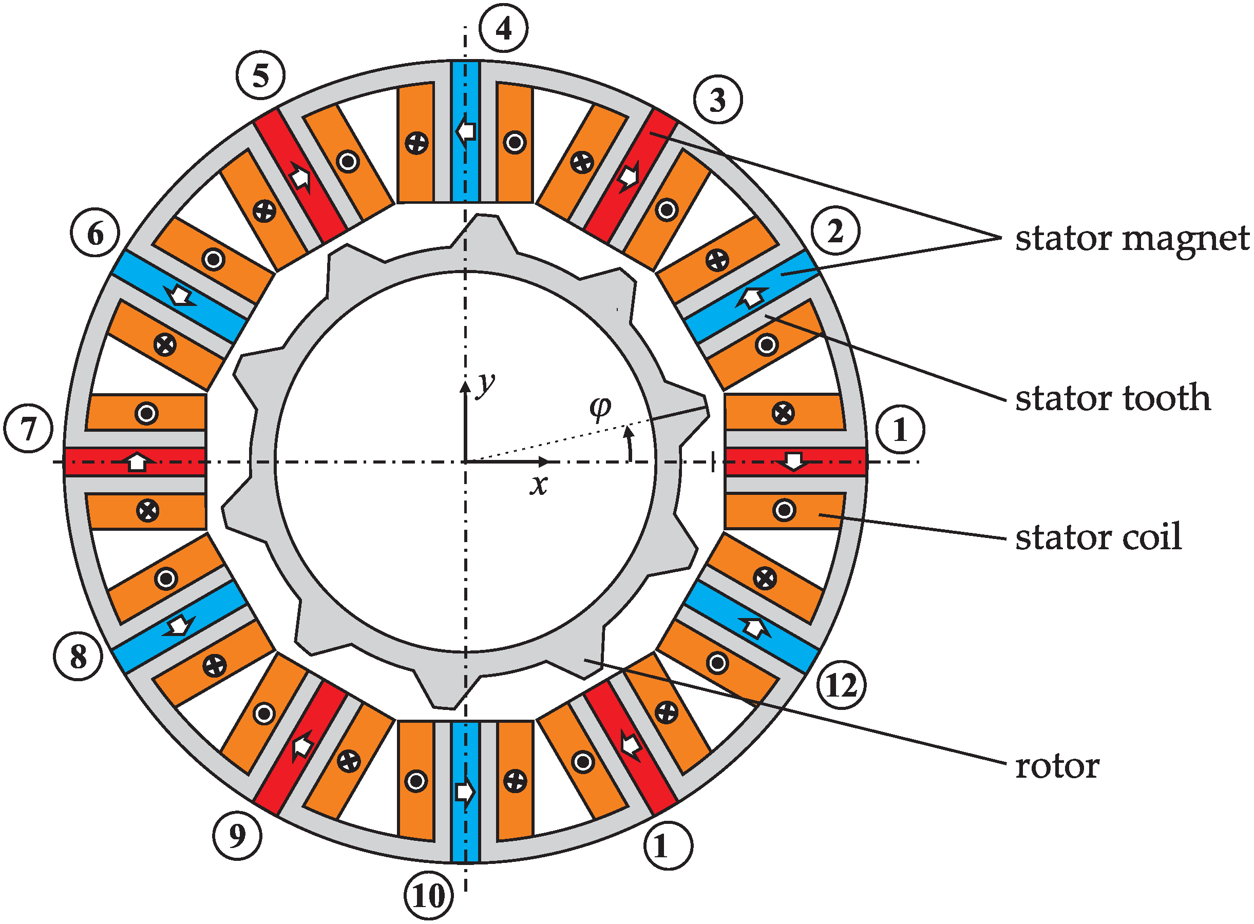
The main structural characteristic of the flux-switching motor, shown in Figure 1, is the placement of the permanent magnets. They are located between the stator teeth, and separated electromagnetically [17]. The flux lines of each permanent magnet close mainly over the neighboring stator teeth, and thus do not penetrate the whole air gap, but especially influence the air gap region close to the permanent magnet. However, there is also a considerable amount of fringing flux closing over the outer side of the stator. To keep stray flux low, a small air gap length (compared to the magnet width) is favorable and necessary.
The air gap flux density in flux-switching machines is often higher than in comparable electric machines, which leads to an increased torque capacity. This is due to the flux concentration capability of this design. The surfaces of the stator teeth normal to the magnetization direction collect permanent magnetic flux, and concentrate it towards the much smaller area of the stator teeth adjoining the air gap.
Conventional flux-switching motors with mechanical bearings represent a relatively recent electrical drive topology introduced in 1955 [18]. Regarding the bearingless version, initial concept studies were published in 2011 [19], and the first prototype went into operation in 2013 [20]. Starting in 2014, Chinese research groups also published their theoretical results regarding bearingless flux-switching motors [21,22]. In 2016 a two-level bearingless flux-switching motor prototype was also reported [23]. Theoretical considerations regarding a linear bearingless flux-switching motor were presented in [24]. These works show the feasibility of this basic concept. Force and torque generation is comparable to standard bearingless slice motors with rotor permanent magnets. The main difference lies in the high rotor pole number of the flux-switching motor, which makes it unfavorable for high speeds. Hence, low speed, high torque direct-drive systems seem to be the most favorable field of application. Due to the saliency of the rotor, the permanent magnetic flux linked with the stator coils changes its direction, resulting in an induced stator back-electromotive force. This means that the energized coil also generates torque [17]. Additionally, the superposition of the stator field and permanent magnetic fields, leads to the creation of bearing forces, due to field strengthening and weakening [20]. Figure 2 shows the principle of force and torque generation schematically. Combining both concepts enables bearingless motor operation for this kind of machine.
The general force generation of one coil is nonlinearly correlated with the corresponding coil current according to [25]:
where Fx and Fy are the forces towards and perpendicular to the coils axis, is is the coil current, ϕ stands for the rotor angle, and the vectors MQ, ML and MC describe the force and torque components that have a quadratic, a linear and no relationship with the coil currents, respectively. This nonlinear relationship complicates the decoupling of torque, x-, and y-force that are necessary for stable bearingless operation. Hence, in the next section, a model of the coil force and torque characteristic is derived to gain a better understanding of this characteristic, and the importance of each component in Equation (1).
3. Modeling of the Single-Phase Characteristic
Suspension forces were computed from the magnetic field distribution in the air gap Bδ, which consists of the permanent magnetic and the stator current excited fields. The relations are:
and:
where l represents the axial rotor and stator stack length, r stands for the mean air gap radius below the salient poles, and µ0 describes the permeability of air. The torque can be computed from several flux linkages by:
Here, Ψi,s denotes the flux created by the stator coil, ΨPM the net flux created by the permanent magnet (PM) and ΨPM the permanent magnetic flux that is linked with the stator coil. All of these fluxes can be computed from the magnetic air gap field distribution Bδ, which results from the superposition of Bδ,i (created by the energized stator coil) and Bδ,PM (excited by the permanent magnets). The permanent magnet was replaced by the current source IPM and a corresponding inductivity.
Assuming linear material behavior without any saturation effects, and ignoring tangential flux components, the magnetic field distribution in the air gap was modeled by the rotor-angle-dependent magnetic permeance of the air gap, which can be computed as the product of the rotor permeance Pr(γ,ϕ) and the stator tooth factor Ps(γ), where γ describes the angle of the point under consideration on the circumference in the middle of the air gap. The stator tooth factor depends on the stator dimensions, and can be expressed by a series of rectangular functions that are defined as:
via:
with:
where Ns denotes the number of stator teeth, tws the stator tooth width, dor the rotor outer diameter and δ the air gap length. A stator tooth factor Ps(γ) = 1 indicates a magnetically conductive stator part at the circumferential angle γ, whereas Ps(γ) = 0 represents the locations of the stator slots. In a similar manner, the expression for the rotor permeance can be formulated as:
with the number of rotor teeth Nr, and twr denoting the rotor tooth width. Here, Pr max represents the permeance of the smaller outer air gap, whereas Pr min stands for the corresponding permeance of the lager outer air gap of the rotor due to the saliency. The air gap flux density can then be calculated using the expression:
The product Ps(γ)∙Pr(γ,ϕ) can be interpreted as an addition of the rotor and stator permeances, which sum up in parallel. The last unknown parameters to be evaluated in Equation (9). were the magneto-motive forces. Figure 3 shows the magnetic circuits with the process by which they were calculated.
For a single energized phase, the magneto-motive force distribution can be computed as:
with the two permeances below the directly energized stator tooth sections:
and the two permeances below the two legs of the return flux path:
The magneto-motive force resulting from the permanent magnets was obtained by superposition of the magneto-motive forces of the individual permanent magnets between the teeth by:
The term (−1)i accounts for the two alternating directions of magnetization in the stator permanent magnets. The shift in the circumferential air gap angle and the rotor angle considers the different locations of the stator teeth holding the permanent magnets. The flux paths of the permanent magnetic field of a single magnet are shown in the right-hand image of Figure 3. With this knowledge, the magneto-motive force distribution can be derived, yielding:
with:
The permanent magnetic source voltage in the operating point was calculated by:
where reluctance Rt1(ϕ) = 1/Pt1(ϕ), Rt2(ϕ) = 1/Pt2(ϕ), and the constant outer stray flux reluctance Ros can be assumed to be a semi-circular flux tube similar to that defined in [26].
The sum of Rt1(ϕ) and Rt2(ϕ) can be assumed to be nearly constant over the rotor angle, exhibiting only small variances compared to the overall mean value. In this case, θPM,op becomes independent of the rotor angle. This simplification was assumed in all of the following considerations. Using Equation (9)., the magnetic field strength in the air gap due to the energized coil and due to the stator permanent magnets can be computed.
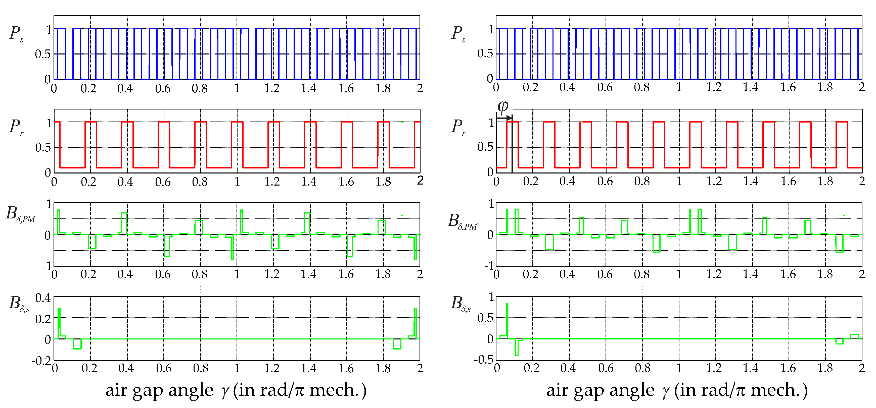
Figure 4 shows the standardized rotor and stator permeances as well as the standardized radial magnetic field strengths for two different rotor angles. The chosen topology featured 12 stator teeth and 10 salient rotor poles. This standard topology for stator permanent magnet flux-switching drives [27] exhibits negligible reluctance forces and low cogging torque. Additionally, the rotor pole width twr was chosen to be 1.5 times the iron tooth width tws, to reduce higher harmonics in the back electromotive force, and to increase the torque [26,28]. As can be seen from the Pr characteristic in Figure 4, the ratio Pr min/Pr max was set at 10% in this example. The scale basis of the B-fields was given by the corresponding maximum absolute magnetic field strength over all rotor angles.
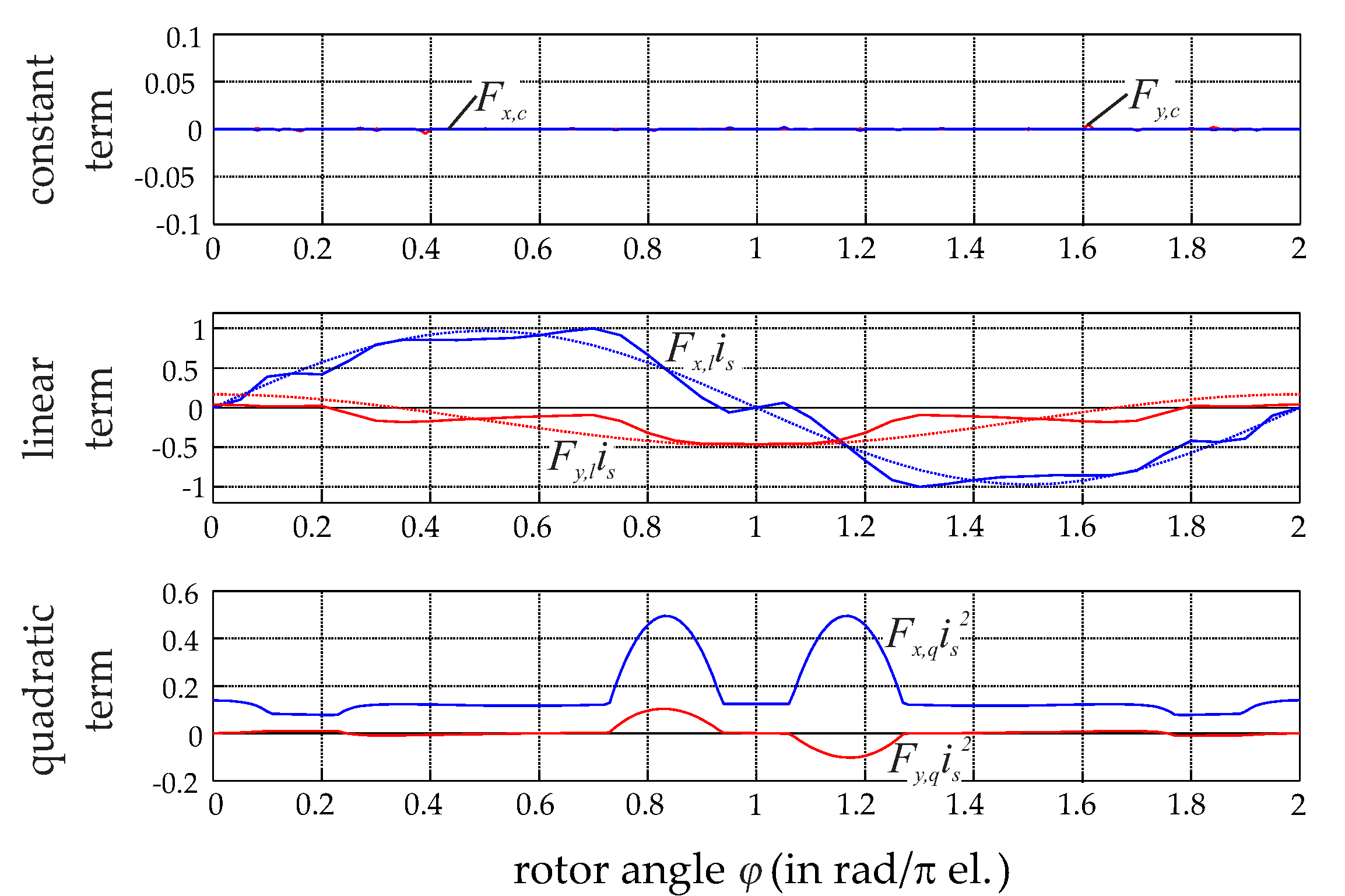
From the B-fields, the radial and tangential forces for one energized coil in relation to the coil axis were calculated using Equations (2) and (3), as illustrated in Figure 5. To obtain these results, the ratio between the maximum permanent magnetic field and the maximum of the field created by the coil current was set to be 2:1. Due to the symmetrical topology, no cogging forces would occur. The forces correlate linearly with the phase current and are approximately sinusoidal. Note that amplitude and offset of the tangential force depend on the ratio of Pr min/Pr max, but only to a limited extent, as illustrated in Figure 5. The force characteristic obtained from the analytical model agreed very well with the finite-element simulation results, and the results published in [23,29]. However, the reluctance forces could not be ignored for all rotor angles in the radial force direction. This was problematic because the state-of-the-art control schemes rely on linearity, which is not given for a significant reluctance part. The choice of iron tooth width tws (relative to the rotor tooth width twr) did not change the general characteristic and influenced only higher harmonic orders.
The torque components from Equation Equation (4). were evaluated with the help of:
as shown in Figure 6. For the variant analyzed with twelve stator teeth and ten rotor teeth, both cogging torque and reluctance torque were negligible. The permanent magnetic stator coil flux, the induced voltage and therefore the linear-current-dependent torque were broadly sinusoidal. This torque is a function of Pr min/Pr max: If this ratio increases, the torque decreases. Again, different rotor tooth widths tws did not change the fundamental wave but influenced the higher harmonic values.
4. Overall Performance of the Bearingless Flux-Switching Motor
The analytical model and the finite-element simulations consistently showed that there was a high quadratic term in the generation of the single-phase x-force. This term arose from a significant armature reaction, which is typically small in systems where the current flux has to penetrate a permanent magnet. This case of a negligible armature reaction is given in nearly all state-of-the-art bearingless slice motors, but here the significant armature reaction resulted in the additional x-force component, with quadratic dependency on the stator current described. Such a quadratic term was incompatible with the proposed nonlinear control scheme, as it relied on a linear relationship. However, the quadratic term in the suspension force could be eliminated when two opposing coils featuring the same single-phase characteristic are connected in the same phase.
4.1. Linearization and Decoupling
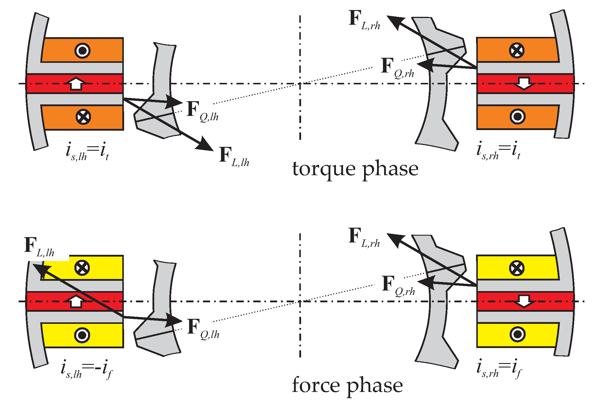
The upper graphic in Figure 7 shows two identical opposing coils energized with the same current it. All forces cancel out, and only torque is created. In contrast, the force phase illustrated in the lower graphic in Figure 7 shows inverted currents in the opposing coils leading to compensation for the quadratic forces, which are independent of the current signs, and summation of the linear forces. An inverted winding direction instead of a negative current would lead to the same effect.
However, for the flux-switching motor the proposed method cancels out all significant quadratic effects, leaving only a force and torque generation that correlates linearly with the stator phase currents. Additionally, separation into only force-creating and only torque-creating phases is achieved, thus implementing a separated and decoupled winding system.
4.2. Topology Evaluation
For a single-phase torque and suspension force characteristic with linear phase-current dependency, the force-current matrix Tm can be deduced [19]. It describes the force and torque generation of all phases and their corresponding currents by the simple relation:
where is is the vector of all stator phase currents. For the control scheme, the inverse relation was more important, because the current-force matrix Km helps to compute the phase currents necessary to generate specific forces and drive torque. A common way to calculate the inverse relation is given by:
which minimizes the copper loss in the coils [25]. With the help of Km, the overall performance of the motor can be estimated. In [20], two benchmark factors were defined to assess the operational characteristic of a bearingless motor. The first factor is called force factor and is defined by:
This represents the overall worst-case torque generation capability Tmin, overall, in relation to the single-phase torque maximum Tmin, phase. In standard sinusoidal multi-phase synchronous machines, this factor is given by m/2, where m is the number of torque phases. This factor was used to normalize the torque factor to values between 0 and 1. A similar factor, called force factor or lift-off factor [30], was defined for the suspension force generation:
These two factors were used to estimate the performance of the bearingless flux-switching motor. The standard topology with 12 stator teeth, featuring a double separated three-phase winding system, was used. Starting with the single-phase force and torque characteristics in Figure 8, the Tm-matrix, Km-matrix and performance factors were computed as functions of the rotor tooth number. The tangential force of the single-phase characteristic depends on the geometry, but only to a very limited extent, as indicated in Figure 8. For the evaluation, a mean representative characteristic of the tangential force was used. As can be seen in Figure 9, there are three different feasible winding systems, all of which were considered in the evaluation.
Table 1 summarizes the resulting performance factors and estimations of cogging torque and cogging force. The best overall bearingless motor was the typical 12/10 topology with winding set (a), but the 12/14 variant with winding scheme (b) also appeared to be promising. The winding scheme (c) featured non-optimal torque generation because the three phases were not shifted by 120° each, and are therefore of minor importance. Based on these results, the common 12/10 bearingless flux-switching topology was chosen to be implemented in a prototype.
4.3. Control Scheme
With the help of Equation (20), a nonlinear feedback transformation was used to decouple the bearing forces and the drive torque in the control system. This method has been proven for bearingless slice motors [12,25]. Figure 10 illustrates this control scheme with outer proportional integral derivative (PID) position and proportional integral (PI) speed controller. Faster nested proportional (P) current controllers impress the necessary currents into the phases with the help of two standard three-phase half-bridge voltage inverters. Measuring the rotor position and the rotor angle is necessary for feedback to close the control loop.
5. Optimization and Design of the Prototype
A 3D finite element optimization of the geometry illustrated in Figure 1 was performed with the software package Maxwell 3D from Ansys. Previous work [26,31] has optimized the geometric parameters of standard (non-bearingless) flux-switching motors with respect to torque generation, from which favorable geometric parameters are known. For instance, choosing a rotor-to-stator diameter ratio between 0.55 and 0.6 was recommended. Additionally, it was favorable to have similar values for the stator tooth width, the magnet width and the stator slot width; a rotor tooth width of about 1.4 times greater than the stator tooth width was recommended.
In addition to the maximization of the motor torque, the increase in passive stabilizing stiffness values and the achievable bearing forces were criteria to be optimized. Finite-element simulations showed that saturation effects severely restricted the parameter choice, especially that of the stator geometry. Due to the limited design space, saturation effects occurred in the iron of the stator teeth (at higher current densities or torque creation). Hence, the geometry was adapted accordingly. The main geometric and electromagnetic characteristic parameters are shown in Figure 11. The corresponding geometric and electromagnetic values after the optimization process are summarized in Table 2 and Table 3. The air gap of 3 mm might seem very large when compared to standard electrical drives. However, bearingless slice motors are often used in applications with hermetically sealed rotors. Therefore, the rotor and stator are separated by a type of chamber wall. To simplify its manufacture and reduce production cost large air gaps of this kind are necessary. The whole optimization process for a bearingless flux-switching slice motor and the optimization criteria are outlined thoroughly in [32].
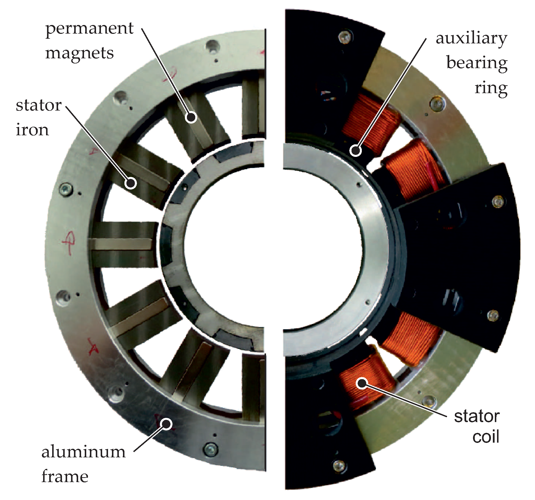
Figure 12 shows the manufactured prototype motor. The laminated stator iron stack is held by an aluminum frame to strengthen the structure. The permanent magnets are glued into pockets that separate the stator elements. The externally wound stator coils are easily slipped onto the stator teeth and connected. Hall and eddy current sensors are placed on the inside of the stator and between the stator teeth to measure the radial deflection and the rotor angle. An aluminum housing covers the rotor and serves as target for the eddy current sensors.
The power electronics inverter used is composed of two three-phase power modules. The rated phase voltage and current of the inverter are 300 V and 15 A, respectively. The nonlinear control scheme for proper decoupling of force and torque is implemented on a 32-bit digital signal processor, which is placed in the integrated control electronics of the inverter.
6. Measurement Results
6.1. Static Measurements
The prototype system was mounted on a test bench with a x-y-z table, load cell, torque sensor and load machine. This setup is universal and allows numerous values to be measured. Generally, the measurements showed good correlation with the finite-element simulation results.
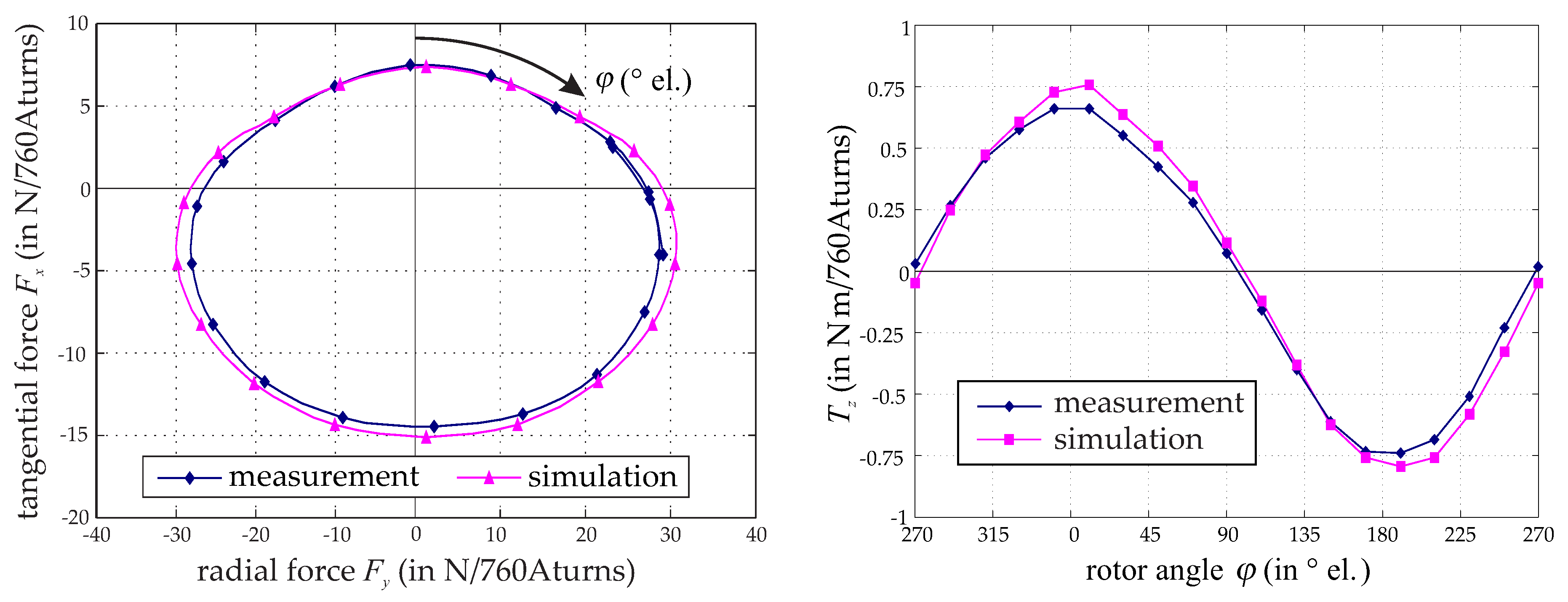
As an example, the force orbit and the torque characteristic at constant magneto-motive force are plotted in Figure 13. The force orbit was unique due to its offset in the tangential direction. Both the force and the torque curves differed only by about 10% from the expected values. However, there was a small asymmetry in the positive and negative half cycle. This fact is well known [33], and results from the nature of the associated permanent magnetic flux paths as the rotor moves. This asymmetry was also visible in the derived model by the characteristic curve of Tz,l(ϕ) in Figure 6.
6.2. Dynamic Suspension Measurements
Measurements were conducted under bearingless operation to check the functionality of the control scheme and its performance. The reaction of the bearingless motor for a step change of the reference position in the x-direction is illustrated in the left-hand image of Figure 14. It was observed that the new position was reached stably after about 80 ms. Due to the controller parameters used, an overshoot and oscillation were observed. Minimal cross coupling between the x- and y-axes was present because there was also a reaction in the y-position signal. This measurement was taken at zero speed.
Furthermore, a disturbance feed-forward x-force step was implemented, again at zero speed. The reaction of the bearingless motor is visible in the right-hand image of Figure 14. The error was compensated for, and the original position signal was reached after 100 ms. However, a cross coupling between the x and y axis was visible. This coupling was compensated by the outer position controllers, as long as it did not become too large. The reason of the coupling lies in the incomplete linearization of the model by the Km(ϕ)-matrix. A decentered rotor, tilting effects, asymmetries in rotor and stator compositions, nonlinearities in the power electronics, higher harmonics in force and torque, as well as saturation effects, were not accounted for, as the control effort would have increased dramatically.
6.3. Motor Measurements
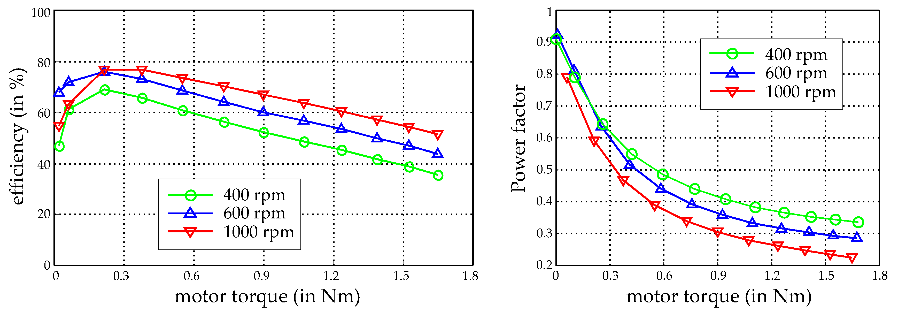
For measuring the performance of the torque generation, the bearingless drive was mechanically suspended and strained by means of a load machine. Several points of operation were evaluated. The efficiency and the load factor, which are plotted in relation to rotor speed and different torque values in Figure 15, were of major interest here.
As can be seen from the measurements, efficiencies of nearly 80% were reached. Compared to standard drives, the efficiency did not seem very high. This was caused by several issues. First, the air gap of this motor with 3 mm was very large. Therefore, relatively high magneto-motive forces needed to be applied, which also led to increased copper losses. Second, due to the slice motor composition, the axial length was only 10 cm and therefore very short. Therefore, the end winding area of the coils was much larger than the active axial coil area. Third, the rotor iron passed through the full hysteresis cycle. This is not the case in standard PM-excited rotors, where the rotor PM flux is not alternating. The efficiency of bearingless slice motors is seldom presented in literature, but examples can be found in Grabner [34], Karutz [35], and Steinert [36]. In these works the efficiency also typically ranged from 60% to 80%, depending on the speed and load. Higher speed usually increases the efficiency, as the mechanical output power increases at the same load and current. However, above a certain speed, iron losses become significant and diminish efficiency.
The power factor is defined as the ratio of the active power to the apparent power in the drive phases. As the inverter had to be dimensioned for apparent power, a high power factor was desirable to keep converter power and therefore costs low. Unfortunately, the stator inductivities in reluctance rotors are typically much higher as in permanent magnet excited rotors. Hence, the power factor is generally smaller. This was also true for the bearingless flux-switching motor. Starting from one at zero-drive torque, the power factor significantly decreased with higher torque (and therefore also higher current) at constant speed. This resulted from the fact that the induced voltage remains constant, while the inductive component rose with the current.
7. Discussion
We have presented a new motor topology, the bearingless flux-switching slice motor. After introducing the concept, we focused on modeling the suspension forces and the drive torque, using an analytical permeance model to examine the force and torque generated by a single coil. Linearization and decoupling of force and torque generation were introduced by connecting opposing coils in series; state-of-the-art nonlinear feedback control methods can thus be employed to stabilize the rotor and generate torque. Based on the single-phase characteristic, performance factors for force and torque were used to describe the performance of the overall bearingless motor. These factors were evaluated for bearingless slice motors featuring 12 stator teeth and a double three-phase winding system. A favorable topology was chosen for realization, optimized by 3D finite-element simulation and manufactured. This bearingless flux-switching slice motor was successfully put into operation, and the feasibility of the design approach demonstrated by measurements.
Examining further bearingless flux-switching motor topologies that feature stator tooth counts other than 12 and other winding sets seems promising for future research. A study aiming to increase the torque by adapting the geometry may also yield useful results. Finally, a novel control scheme that can deal with quadratic current dependencies on suspension forces and drive torque would remove the need for serial connection of opposing coils, thus greatly enhancing the freedom of design and the utilization of the stator coils.
Acknowledgments
Parts of this work were supported by the Linz Center of Mechatronics GmbH (LCM), a K2 centre of the COMET program of the Austrian Government. The authors thank the Austrian and Upper Austrian Governments for their support.
Author Contributions
W.G. conceived of the idea for the bearingless flux-switching slice motor, created the analytical single-phase model, estimated the overall bearingless system performance and wrote the paper. K.R. optimized, designed and built the prototype motor and conducted the measurements.
Conflicts of Interest
The authors declare no conflict of interest.
References
- Schöb, R.; Barletta, N. Principle and application of a bearingless slice motor. In Proceedings of the 5th International Symposium on Magnetic Bearings (ISMB), Kanazawa, Japan, 28–30 August 1996; pp. 333–338. [Google Scholar]
- Asama, J.; Fukao, T.; Chiba, A.; Rahman, M.A.; Oiwa, T. A design consideration of a novel bearingless disk motor for artificial hearts. In Proceedings of the 1st IEEE Energy Conversion Congress and Exposition (ECCE), San Jose, CA, USA, 20–24 September 2009; pp. 1693–1699. [Google Scholar]
- Nussbaumer, T.; Raggl, K.; Bösch, P.; Kolar, J.W. Trends in integration for magnetically levitated pump systems. In Proceedings of the Power Conversion Conference (PCC), Nagoya, Japan, 2–5 April 2007; pp. 1551–1558. [Google Scholar]
- Nussbaumer, T.; Karutz, P.; Zürcher, F.; Kolar, J.W. Magnetically levitated slice motors—An overview. IEEE Trans. Ind. Appl. 2011, 47, 754–766. [Google Scholar] [CrossRef]
- Warberger, B.; Kaelin, R.; Nussbaumer, T.; Kolar, J.W. 50-Nm/2500-W bearingless motor for high-purity pharmaceutical mixing. IEEE Trans. Ind. Electron. 2012, 59, 2236–2247. [Google Scholar] [CrossRef]
- Mitterhofer, H.; Mrak, B.; Amrhein, W. Suitability investigation of a bearingless disk drive for micro turbine applications. In Proceedings of the IEEE Energy Conversion Congress and Exposition (ECCE), Denver, CO, USA, 15–19 Sept. 2013; pp. 2480–2485. [Google Scholar]
- Zingerli, C.M.; Coray, I.; Weber, J.; Nussbaumer, T.; Kolar, J.W. Scaling of magnetically levitated homopolar hollow-shaft machines. In Proceedings of the 10th IEEE International Conference on Power Electronics and Drive Systems (PEDS), Kitakyushu, Japan, 22–25 April 2013; pp. 54–59. [Google Scholar]
- Huwyler, S.; Schrag, D.; Gilbert, R.; Thorsen, T.; Schöb, R.; Hahn, J. Bearingless in-line viscometer for the semiconductor industry. Proc. IEEE Sens. 2003, 2, 1077–1081. [Google Scholar]
- Asami, K.; Chiba, A.; Rahman, M.A.; Hoshino, T.; Nakajima, A. Stiffness analysis of a magnetically suspended bearingless motor with permanent magnet passive positioning. IEEE Trans. Magn. 2005, 41, 3820–3822. [Google Scholar] [CrossRef]
- Sugimoto, H.; Miyoshi, M.; Chiba, A. Low speed test in two-axis actively positioned bearingless machines with non-collocated structure for wind power applications. In Proceedings of the IEEE Energy Conversion Congress and Exposition (ECCE), Montreal, QC, Canada, 20–24 September 2015; pp. 799–804. [Google Scholar]
- Gruber, W.; Briewasser, W.; Rothböck, W.; Schöb, R. Bearingless slice motor concepts without permanent magnets in the rotor. In Proceedings of the IEEE International Conference on Industrial Technology (ICIT), Cape Town, South Africa, 25–28 February 2013; pp. 259–265. [Google Scholar]
- Gruber, W.; Rothböck, M.; Schöb, R. Design of a novel homopolar bearingless slice motor with reluctance rotor. IEEE Trans. Ind. Appl. 2015, 51, 1456–1464. [Google Scholar] [CrossRef]
- Rao, J.; Hijikata, W.; Shinshi, T. A permanent magnet free bearingless motor for disposable centrifugal blood pump. In Proceedings of the 14th International Symposium on Magnetic Bearing (ISMB), Linz, Austria, 11–14 August 2014; pp. 183–186. [Google Scholar]
- Zhu, Z.Q.; Howe, D. Electrical machines and drives for electric, hybrid, and fuel cell vehicles. Proc. IEEE 2007, 95, 746–765. [Google Scholar] [CrossRef]
- Gruber, W.; Radman, K.; Schöb, R. Design of a bearingless flux-switching slice motor. In Proceedings of the Power Electronics Conference (IPEC—ECCE ASIA), Hiroshima, Japan, 18–21 May 2014; pp. 1691–1696. [Google Scholar]
- Radman, K.; Bulic, N.; Gruber, W. Loss analysis of a bearingless flux-switching slice motor. In Proceedings of the 14th International Symposium on Magnetic Bearings (ISMB), Linz, Austria, 11–14 August 2014; pp. 210–215. [Google Scholar]
- Hoang, E.; Ahmed, H.B.; Lucidarme, J. Switching flux permanent magnet poly-phased synchronous machines. In Proceedings of the 7th European Conference on Power Electronics and Applications (EPE), Trondheim, Norway, 8–10 September 1997; Volume 3, pp. 903–908. [Google Scholar]
- Rauch, S.E.; Johnson, L.J. Design principles of flux-switch alternators. Trans. Am. Inst. Electr. Eng. Part III Power Appar. Syst. 1955, 74, 1261–1268. [Google Scholar]
- Gruber, W.; Briewasser, W.; Rothböck, M.; Schöb, R.; Amrhein, W. Bearingless reluctance slice motors. In Proceedings of the 13th International Symposium on Magnetic Bearings (ISMB), Arlington, TX, USA, 6–9 August 2012. [Google Scholar]
- Gruber, W.; Bauer, W.; Radman, K.; Amrhein, W.; Schöb, R. Considerations Regarding Bearingless Flux-Switching Slice Motors. In Proceedings of the 1st Brazilian Workshop on Magnetic Bearings, Rio de Janeiro, Brazil, 25–26 October 2013; Available online: www.magneticbearings.org (accessed on 28 November 2016).
- Jia, H.; Fang, C.; Zhang, T. Finite element analysis of a novel bearingless flux-switching permanent magnet motor with the single winding. In Proceedings of the 17th International Conference on Electrical Machines and Systems (ICEMS), Hangzhou, China, 22–25 October 2014; pp. 2315–2318. [Google Scholar]
- Li, H.; Zhu, H. Design of bearingless flux-switching permanent-magnet motor. IEEE Trans. Appl. Superconduct. 2016, 26, 1–5. [Google Scholar] [CrossRef]
- Ni, T.; Wang, X.; Ding, Q.; Wang, Y. Novel structure of bearingless flux-switching motor for improvement of levitation force characteristics. In Proceedings of the 8th International Power Electronics and Motion Control Conference (IPEMC-ECCE Asia), Hefei, China, 22–26 May 2016; pp. 1929–1933. [Google Scholar]
- Jastrzbeski, R.P.; Jaatinen, P.; Pyrhönen, O. Modelling and control design simulations of permanent magnet flux-switching linear bearingless motor. In Proceedings of the 15th International Symposium on Magnetic Bearing (ISMB), Kitykyushu, Japan, 3–6 August 2016; pp. 296–303. [Google Scholar]
- Silber, S. Power optimal current control scheme for bearingless pm motors. In Proceedings of the 7th International Symposium on Magnetic Bearings (ISMB), Zurich, Switzerland, 23–25 August 2000; pp. 401–406. [Google Scholar]
- Zhu, Z.Q.; Pang, Y.; Howe, D.; Iwasaki, S.; Deodhar, R.; Pride, A. Analysis of electromagnetic performance of flux-switching permanent-magnet machines by non-linear adaptive lumped parameter magnetic circuit model. IEEE Trans. Magn. 2005, 41, 4277–4287. [Google Scholar] [CrossRef]
- Chen, J.T.; Zhu, Z.Q. Winding configurations and optimal stator and rotor pole combination of flux-switching pm brushless ac machines. IEEE Trans. Energy Conv. 2010, 25, 293–302. [Google Scholar] [CrossRef]
- Wei, H.; Ming, C.; Zhu, Z.Q.; Howe, D. Analysis and optimization of back EMF waveform of a flux-switching permanent magnet motor. IEEE Trans. Energy Conv. 2008, 23, 727–733. [Google Scholar] [CrossRef]
- He, W.; Hantong, W.; Fei, R.; Zhou, Y. Research on control strategy for a double-winding bearingless flux-switching machine with alternating excited orthogonal suspension windings. In Proceedings of the 8th IEEE International Power Electronics and Motion Control Conference (IPEMC-ECCE Asia), Hefei, China, 22–26 May 2016; pp. 821–826. [Google Scholar]
- Mitterhofer, H.; Mrak, B.; Gruber, W. Comparison of high-speed bearingless drive topologies with combined windings. IEEE Trans. Ind. Appl. 2015, 51, 2116–2122. [Google Scholar] [CrossRef]
- Zhu, Z.Q.; Pang, Y.; Chen, J.; Xia, Z.P.; Howe, D. Influence of design parameters on output torque of flux-switching permanent magnet machines. In Proceedings of the IEEE Vehicle Power and Propulsion Conference (VPPC), Harbin, China, 3–5 September 2008; pp. 1–6. [Google Scholar]
- Radman, K.; Bulic, N.; Gruber, W. Geometry optimization of a bearingless flux-switching slice motor. In Proceedings of the IEEE International Electric Machines & Drives Conference (IEMDC), Coeur d’Alene, ID, USA, 10–13 May 2015; pp. 1695–1701. [Google Scholar]
- Hua, W.; Cheng, M.; Zhu, Z.Q.; Howe, D. Analysis and optimization of back emf waveform of a flux-switching permanent magnet motor. IEEE Trans. Energy Conv. 2008, 23, 727–733. [Google Scholar] [CrossRef]
- Grabner, H. Dynamik und Ansteuerkonzepte Lagerloser Drehfeld-Scheibenläufermotoren in radialer Bauform. Ph.D. Thesis, Johannes Kepler University (JKU) Linz, Linz, Austria, 2006. (In German). [Google Scholar]
- Karutz, P. Magnetically Levitated 2-Level Slice Motor for Application in High Purity Process Environments. Ph.D. Thesis (No. 18809), Eidgenössische Technische Hochschule (ETH) Zurich, Zurich, Switzerland, 2010. [Google Scholar]
- Steinert, D. Der Nutenlose Lagerlose Scheibenläufermotor. Ph.D. Thesis (No. 22961), Eidgenössische Technische Hochschule (ETH) Zurich, Zurich, Switzerland, 2015. (In German). [Google Scholar]
Sample Availability: All ISMB papers are available online at www.magneticbearings.org (accessed on 28 November 2016). |
Figure 1.
Cross-section of a flux-switching motor with twelve stator and 10 rotor teeth. The arrows indicate the direction of magnetization.
Figure 1.
Cross-section of a flux-switching motor with twelve stator and 10 rotor teeth. The arrows indicate the direction of magnetization.

Figure 2.
Principles of torque and force generation: Torque is created by an energized stator coil with angle-dependent permanent magnetic flux linkage (illustrated at the top for two different rotor angles), while force is created by field strengthening and weakening (illustrated at the bottom).
Figure 2.
Principles of torque and force generation: Torque is created by an energized stator coil with angle-dependent permanent magnetic flux linkage (illustrated at the top for two different rotor angles), while force is created by field strengthening and weakening (illustrated at the bottom).
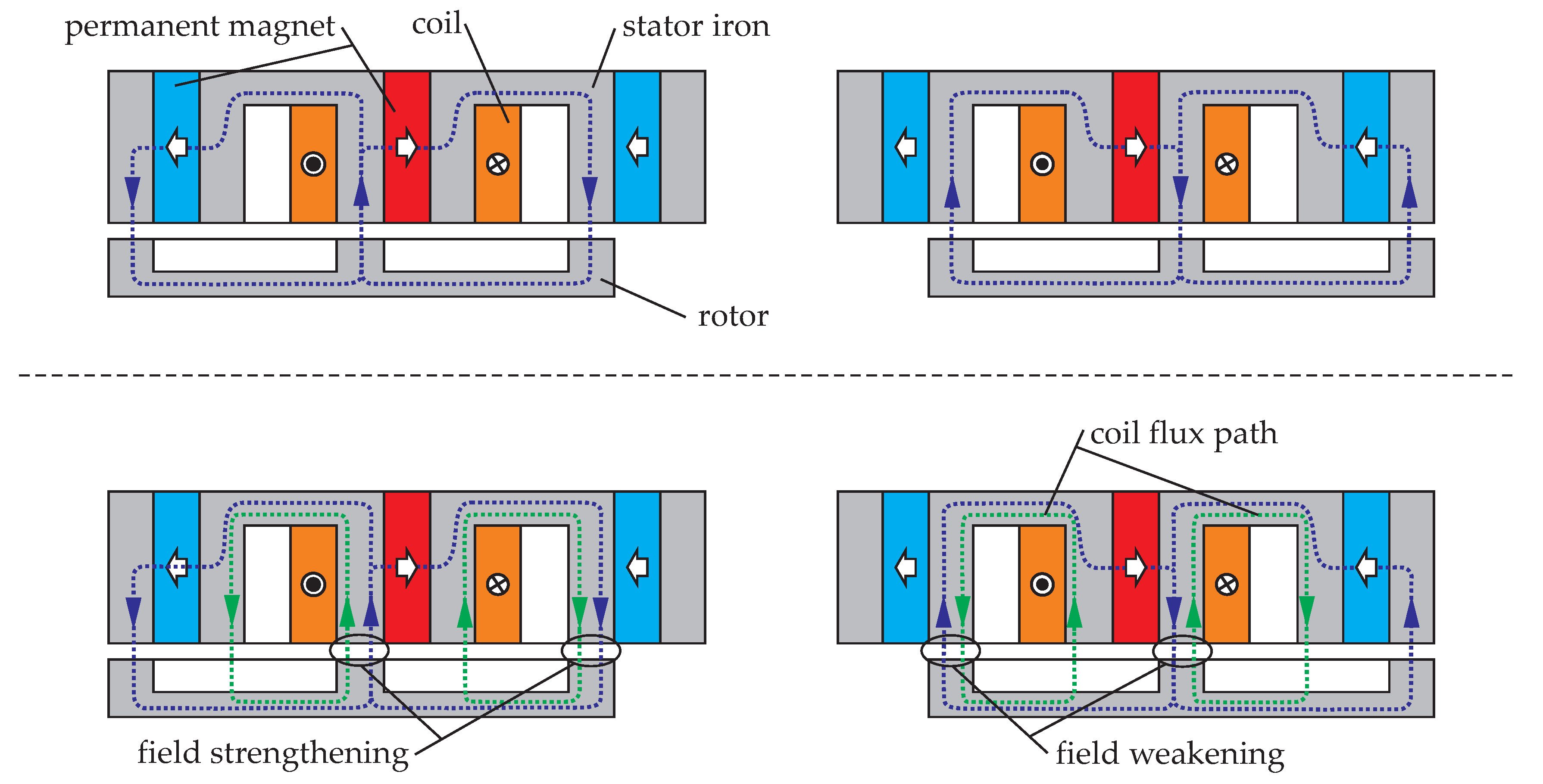
Figure 3.
Unrolled cross-sectional part of the flux-switching motor, with the field lines created by the stator coil current (left) and one permanent magnet placed between the stator teeth (right).
Figure 3.
Unrolled cross-sectional part of the flux-switching motor, with the field lines created by the stator coil current (left) and one permanent magnet placed between the stator teeth (right).
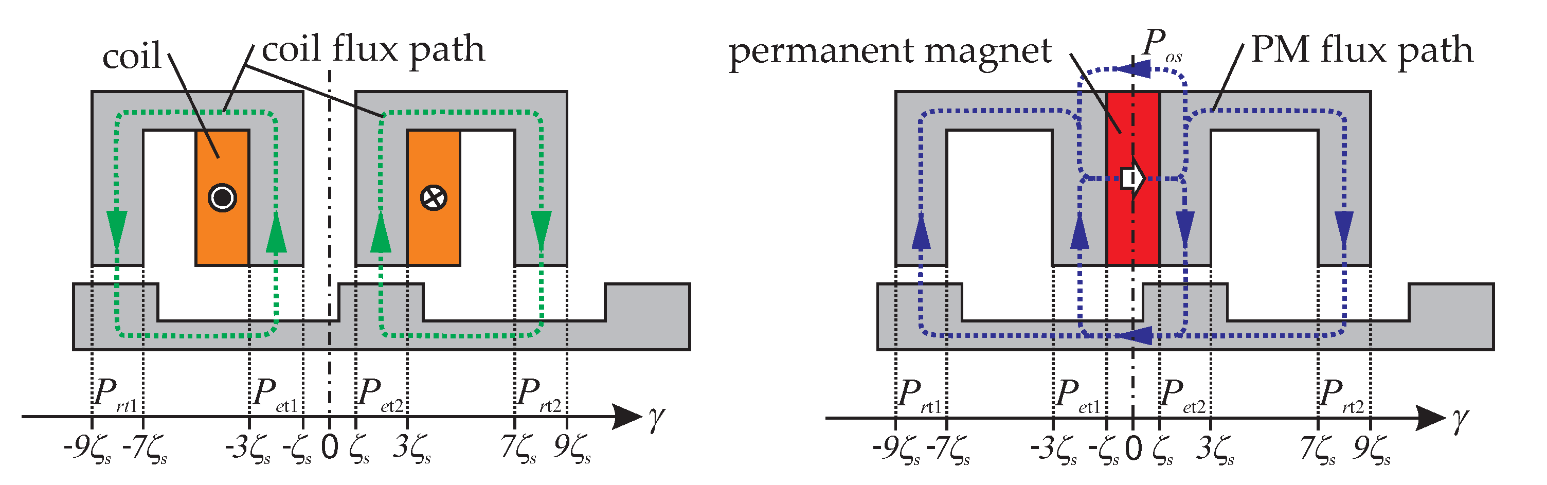
Figure 4.
Normalized permeances and air gap flux densities of the flux-switching motor for mechanical rotor angles ϕ of 0° (left) and 16° (right).
Figure 4.
Normalized permeances and air gap flux densities of the flux-switching motor for mechanical rotor angles ϕ of 0° (left) and 16° (right).

Figure 5.
Analytically computed and separated suspension force components; all curves were normalized with the maximum of Fx,l(ϕ)is.
Figure 5.
Analytically computed and separated suspension force components; all curves were normalized with the maximum of Fx,l(ϕ)is.

Figure 6.
Analytically computed flux linkages (left) and separated torque components (right); all curves were normalized with the maximum of ΨPM,s and Tz,l.
Figure 6.
Analytically computed flux linkages (left) and separated torque components (right); all curves were normalized with the maximum of ΨPM,s and Tz,l.
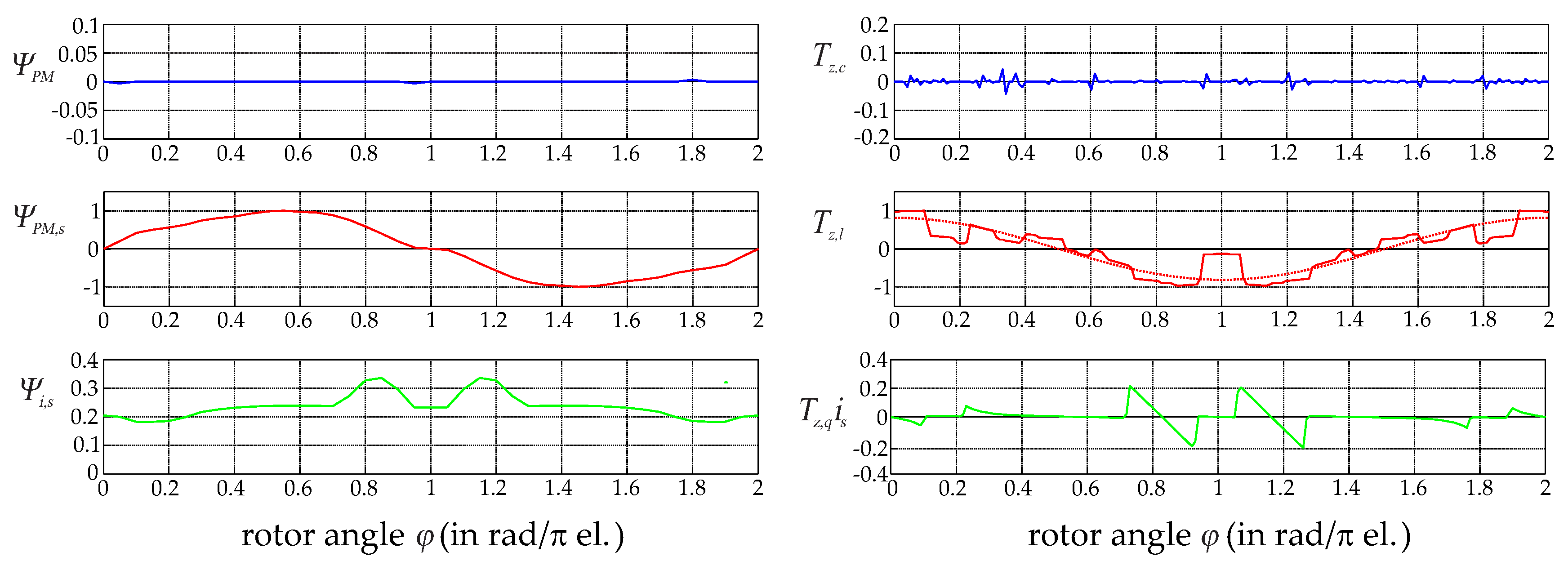
Figure 7.
Connection of two opposing coils in series to compensate for the quadratic force component, and to decouple force and torque.
Figure 7.
Connection of two opposing coils in series to compensate for the quadratic force component, and to decouple force and torque.

Figure 8.
Single-phase torque and force characteristics of the linearized and decoupled bearingless flux-switching slice motor.
Figure 8.
Single-phase torque and force characteristics of the linearized and decoupled bearingless flux-switching slice motor.
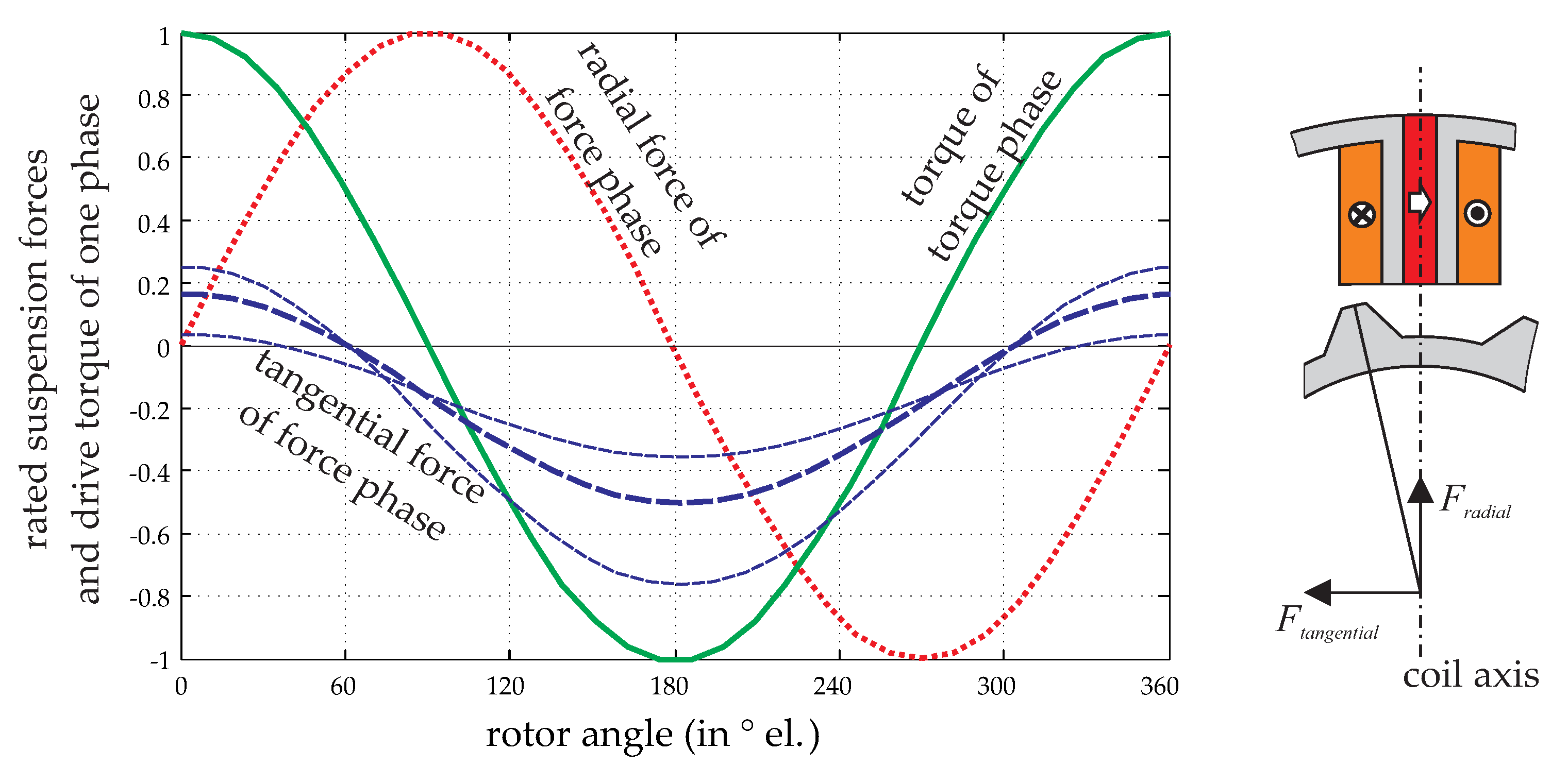
Figure 9.
Bearingless flux-switching motor compositions with 12 stator teeth and double three-phase winding system.
Figure 9.
Bearingless flux-switching motor compositions with 12 stator teeth and double three-phase winding system.
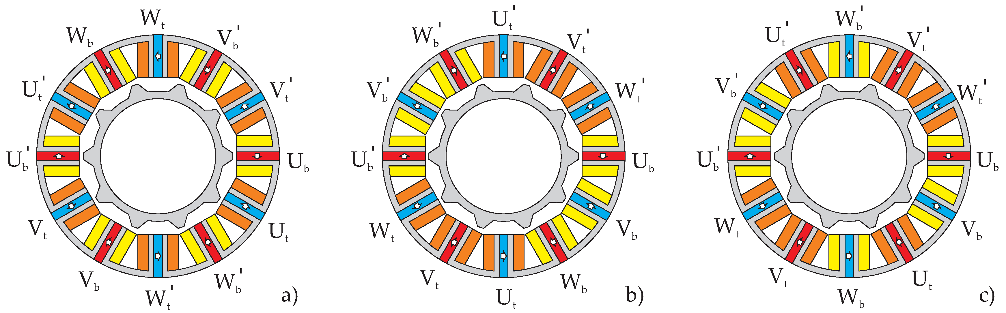
Figure 10.
Block diagram of the nonlinear feedback control scheme for controlling the double three-phase bearingless flux-switching slice motor.
Figure 10.
Block diagram of the nonlinear feedback control scheme for controlling the double three-phase bearingless flux-switching slice motor.
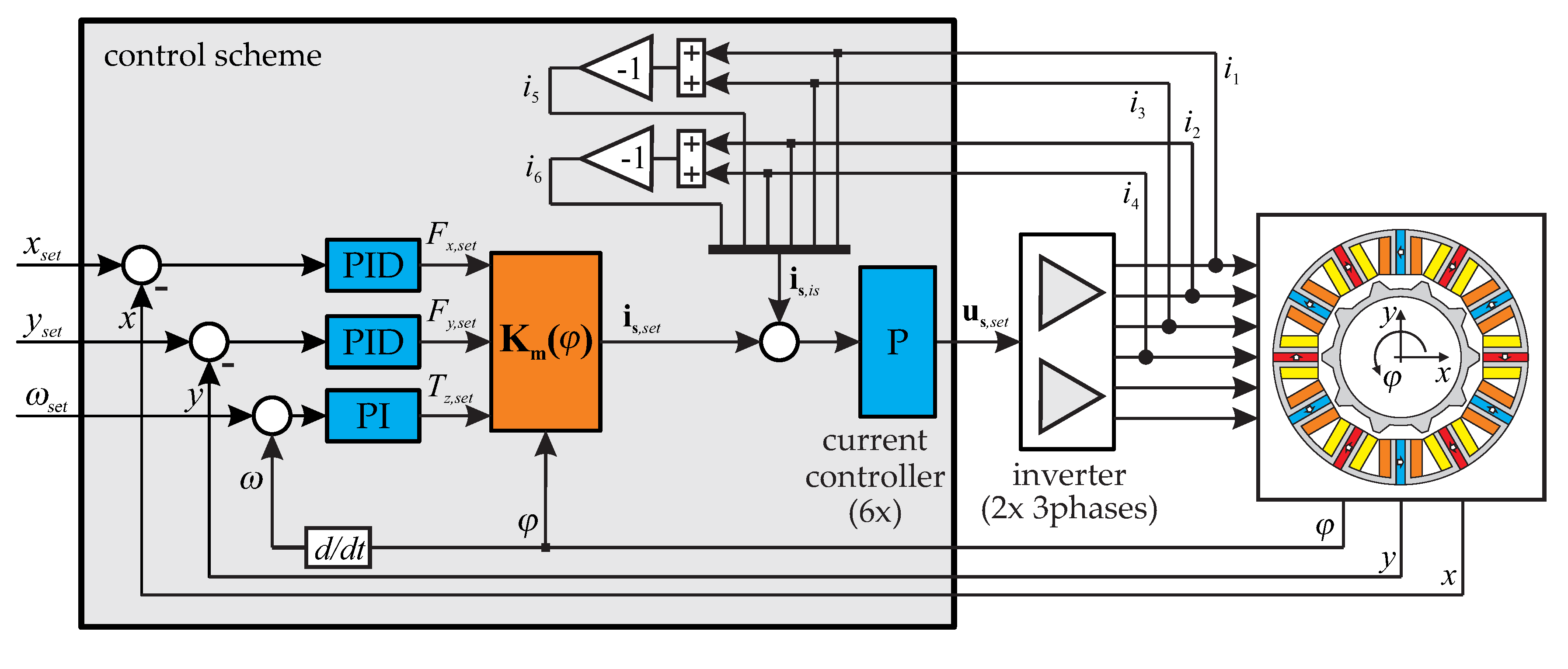
Figure 11.
Geometric parameters of the bearingless flux-switching motor.
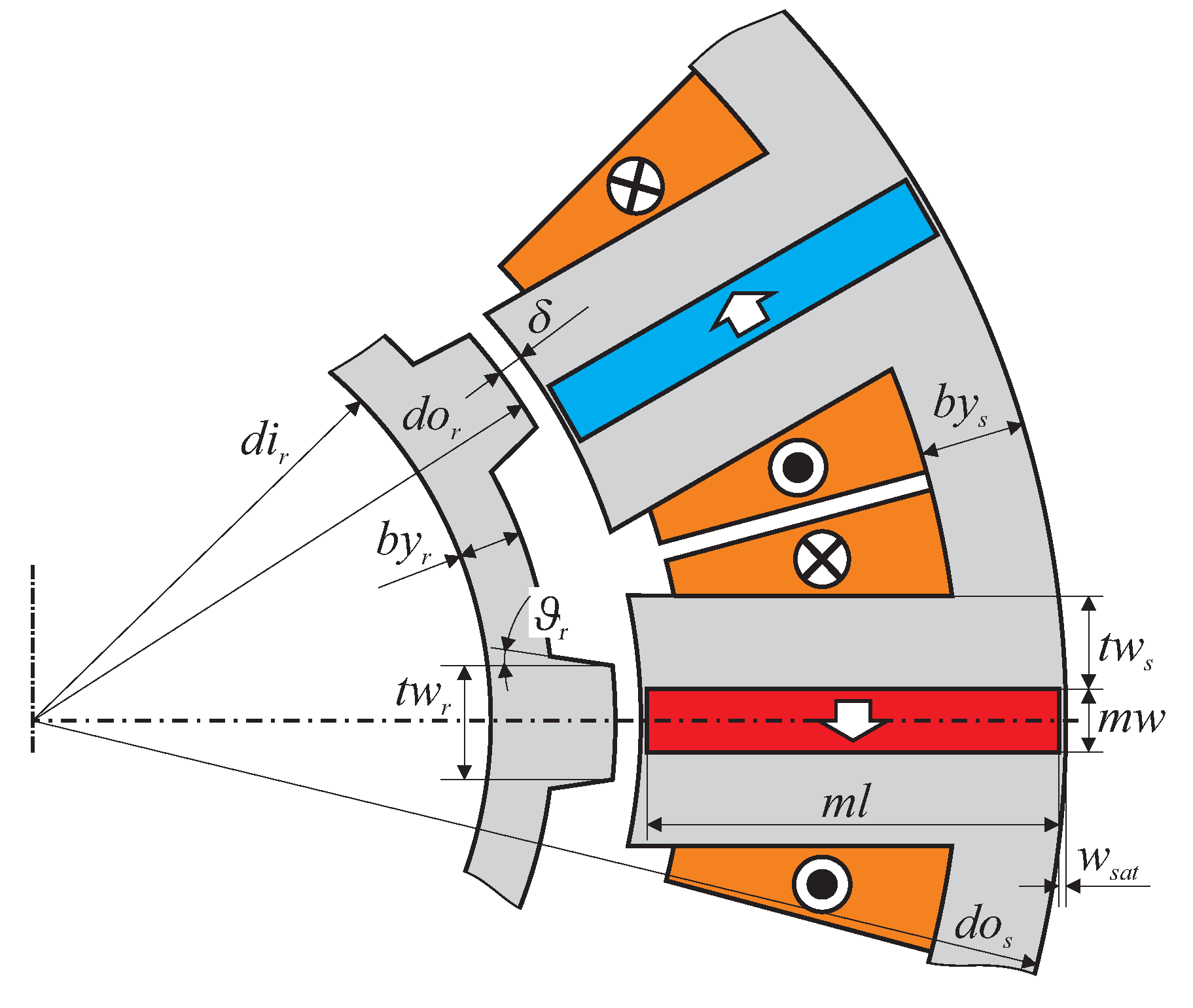
Figure 12.
Photograph of the bearingless flux-switching motor prototype.

Figure 13.
Comparison of the finite-element simulated and measured single-phase characteristics of the suspension forces (left), and the torque (right).
Figure 13.
Comparison of the finite-element simulated and measured single-phase characteristics of the suspension forces (left), and the torque (right).

Figure 14.
Reactions of the x- and y-positions following a step in the set-point value (left), and a step change in the suspension force (right).
Figure 14.
Reactions of the x- and y-positions following a step in the set-point value (left), and a step change in the suspension force (right).
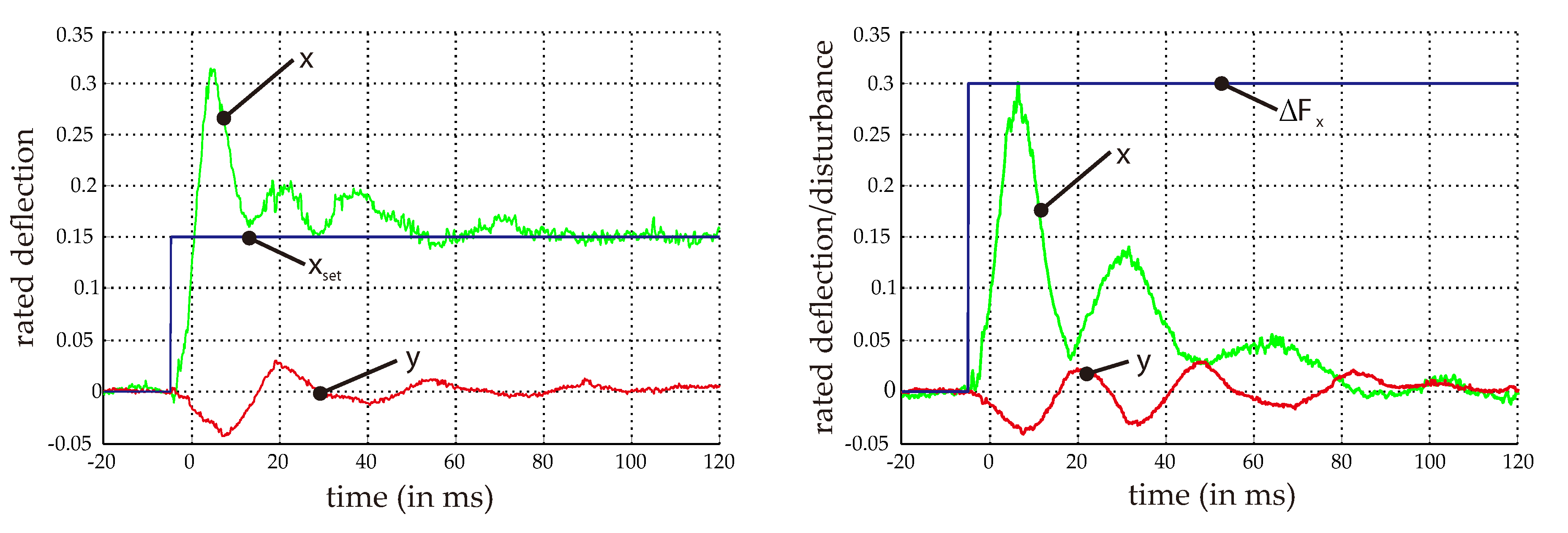
Figure 15.
Efficiency and load factor of the manufactured bearingless flux-switching motor.

Table 1.
Performance factors of different bearingless flux-switching motors, featuring twelve stator teeth and a double three-phase winding system.
Table 1.
Performance factors of different bearingless flux-switching motors, featuring twelve stator teeth and a double three-phase winding system.
| Winding Scheme (Corresponding to Figure 9) | Number of Stator Teeth Ns = 12 | |||||||||
|---|---|---|---|---|---|---|---|---|---|---|
| Nr = 8 | Nr = 10 | Nr = 12 | Nr = 14 | Nr = 16 | ||||||
| (a) double three-phase | cf = 0 | ct = 1 | cf = 0.5 | ct = 1 | cf = 0.2 | ct = 0 * | cf = 0 | ct = 1 | cf = 0.5 | ct = 1 |
| CF↓ | CT− | CF↓ | CT− | CF↓ | CT↑ | CF↓ | CT− | CF↓ | CT− | |
| (b) double three-phase | cf = 0.2 | ct = 1 | cf = 0.1 | ct = 1 | cf = 0.2 | ct = 0 * | cf = 0.4 | ct = 1 | cf = 0.3 | ct = 1 |
| CF↓ | CT− | CF↓ | CT− | CF↓ | CT↑ | CF↓ | CT− | CF↓ | CT− | |
| (c) double three-phase | cf = 0.2 | ct = 0.6 | cf = 0.3 | ct = 0.6 | cf = 0.2 | ct = 0 * | cf = 0.3 | ct = 0.6 | cf = 0.2 | ct = 0.6 |
| CF↓ | CT− | CF↓ | CT− | CF↓ | CT↑ | CF↓ | CT− | CF↓ | CT− | |
Dark and light red backgrounds indicate: very poor and poor respectively, green: good, and yellow: moderate performance. CF stands for cogging force and CT for cogging torque. The symbols ↓, − and ↑ indicate low, medium and high values, respectively. A * indicate drives which cannot create torque at certain rotor angles but might feature acceptable mean torque values considering one electrical period.
Table 2.
Main geometric parameters of the prototype drive.
| Variable | Description | Value | Unit |
|---|---|---|---|
| dos | stator iron outer diameter | 266 | mm |
| dor | rotor outer diameter | 150 | mm |
| hz | axial rotor and stator length | 10 | mm |
| δ | magnetic air gap | 3 | mm |
| mw | magnet width | 8.5 | mm |
| ml | magnet length | 54 | mm |
| laminated iron material | M330-35A | ||
| permanent magnet material | NdFeB N38 | ||
Table 3.
Main electromagnetic parameters of the prototype drive.
| Variable | Description | Value | Unit |
|---|---|---|---|
| kr | radial stiffness | −41.6 | N/mm |
| kz | axial stiffness | 7.3 | N/mm |
| kϕ | tilt stiffness | 21.4 | Nm/rad |
| Jmax | maximum current density | 6 | A/mm2 |
| Fmax | maximum bearing force | 10 | N |
| Tmax | maximum drive torque | 1.5 | Nm |
© 2017 by the authors. Licensee MDPI, Basel, Switzerland. This article is an open access article distributed under the terms and conditions of the Creative Commons Attribution (CC BY) license (http://creativecommons.org/licenses/by/4.0/).
Share and Cite
MDPI and ACS Style
Gruber, W.; Radman, K. Modeling and Realization of a Bearingless Flux-Switching Slice Motor. Actuators 2017, 6, 12. https://doi.org/10.3390/act6020012
AMA Style
Gruber W, Radman K. Modeling and Realization of a Bearingless Flux-Switching Slice Motor. Actuators. 2017; 6(2):12. https://doi.org/10.3390/act6020012
Chicago/Turabian StyleGruber, Wolfgang, and Karlo Radman. 2017. "Modeling and Realization of a Bearingless Flux-Switching Slice Motor" Actuators 6, no. 2: 12. https://doi.org/10.3390/act6020012
Note that from the first issue of 2016, this journal uses article numbers instead of page numbers. See further details here.