1. Introduction
Recently, the field of Nanoelectromechanical Systems (NEMS) has become one of the most emerging fundamental and applied research areas. It is essentially considered as a multi-disciplinary research branch involving many engineering applications such as: nano-switches, nano-tweezers, nano-grippers, nano-resonators, nano-actuators, etc. [
1]. Estimating accurately the pull-in characteristics of NEMS-based devices has been the center of research attention over the past few years, mostly because predicting these parameters forms the basis of utilizing these tiny structures as sensors and actuators of distinguishing properties. In addition, these characteristics could represent, for the majority of the designers in this area, an effective way to extract the mechanical properties of such nano-structures.
One of the most assumed configurations in designing NEMS devices is the clamped-clamped nanobeam arrangement. Clamped-clamped NEMS-based nanobeams have been under extensive research in the NEMS community, and they find potential in many applications such as random access memory, resonating devices for high-frequency operation, fast switching in communication networking applications [
2], energy harvesters [
3], etc.
Among the different actuation mechanisms for such nano-structures, the electrostatic actuation technique is the most commonly used because of its numerous advantages such as: the large force generation, the easy Complementary Metal-Oxide-Semiconductor (CMOS) integration, the compatibility with all the micro-/nano-manufacturing processes, etc. However, it is worth noting that the efficiency of this technique is restricted by the well-known structural instability named the “pull-in” collapse [
4]. This structural instability was first discovered for micro-actuators and revealed to be a function of the actuating electric force [
4]. However, going down further in the nano scale, this structural instability was shown to be dependent on other forces, mainly the intermolecular forces, for nanobeam-based actuators. It should be pointed out that the nano-actuator where the initial gaps are below 100 nm, the intermolecular forces (Casimir and van der Waals forces essentially) are considered prominent and strong and become comparable to the electrostatic actuating forces and even overriding other attractive intermolecular forces. During the pull-in instability scenario, the nanobeam restoring force (i.e., its overall stiffness) is no longer capable of balancing the electric actuating force, resulting in the collapse of the nano-structure. Furthermore, other than the nano-structure restoring and actuating forces, other highly nonlinear intermolecular forces such as the van der Waals and the Casimir forces may even significantly distress the pull-in characteristics of the nano-actuator. Occasionally, these intermolecular forces may lead to the nano-structure restoring elastic forces depending on the initial gap size and therefore may lead to collapse even without the need to consider any electric actuating voltage [
5,
6].
An extra and important non-linear effect in doubly-clamped nanobeam designs is the geometric mid-plane stretching effect. This effect frequently results in a significant increase in beam stiffness (i.e., its resulting restoring elastic force) and consequently may drastically alter its pull-in characteristics. Considering the combined effects of the intermolecular forces and the mid-plane stretching effect is extremely important for the successful design, analysis and fabrication of NEMS-based electrostatically-actuated nanobeams. Though several extensive investigations on the pull-in characteristics of NEMS devices, mainly assuming semi-analytical, analytical and closed-form approximations for different nano-cantilever configurations [
5,
6,
7,
8,
9], are available in recent literature, only a few attempts [
10,
11,
12,
13,
14,
15] performed a similar analysis on the doubly-clamped nanobeam while taking into consideration the combined effects of the intermolecular forces and the nonlinear mid-plane stretching effect. Most of the cited literature investigated the doubly-clamped nanobeam pull-in characteristics assuming a lumped system modeling and/or numerical simulation approaches [
10,
11]. Others included in their modeling the nonlocal elasticity theory [
12], the modified strain gradient theory [
13], the modified Adomian method [
14], the hybrid nonlocal beam model [
15], etc. Only recently, Shokravi [
16] investigated the dynamic pull-in and pull-out problems of nanoplate-based NEMS switches under electrostatic and Casimir forces assuming Eringen's nonlocal theory [
16].
Another major effect at the nano-scale that may alter nanobeam-based actuators is their surface effects. Few previous experiments [
17] demonstrated that the surface layer plays an important role in the structural behavior of nanoscale-based structures. In the classical continuum mechanics, the effect of the surface layer is typically ignored. However, for nanoscale devices, because of high surface-to-volume ratios, the influence of the surface layer on the overall dynamic behavior of the nanostructure could no longer be neglected [
18,
19]. Therefore, in one of our previous investigations [
20], we studied the instability characteristics of free-standing nanowires based on the consideration of Casimir attractive forces in addition to the surface effects.
The accessibility to simple analytical expressions/generalized closed-form solutions for estimating the pull-in characteristics of doubly-clamped NEMS-based nanobeams is still not properly investigated in the literature. Although few groups [
12,
13] attempted to formulate analytical solutions for the pull-in instability of nano-devices, their methods mostly suffer from complexity (complicated mathematical operations) and numerical integration techniques. Another limitation is that the final closed-form expression involves and also is dependent on the ‘pull-in deflection’ factor [
12,
13], which itself requires further computation.
Therefore, the present work aims at deriving simple generalized closed-form expressions for estimating the critical pull-in design characteristics of the fixed-fixed nanobeam that hopefully will serve as fast, simple and accurate design guidelines for NEMS engineers. The plan is first to formulate the doubly-clamped nanobeam problem assuming a Euler–Bernoulli beam model, while considering the mid-plane stretching effect, the van der Waals and Casimir forces and the nonlinear quadratic electrostatic forces while accounting for the fringing effects. Then, a Galerkin-based modal decomposition technique will be carried out. Its resulting integrals and higher-order polynomials will be solved numerically to acquire the doubly-clamped nanobeam pull-in parameters (the critical dimension limits, the maximum detachment length and the minimum gap size to pull-in). Afterward, a curve fitting process will be used to provide simple and readymade analytical expressions for the pull-in voltage function of the mid-plane stretching, the fringing electric field and the intermolecular force parameters.
The main advantage of the above planned approach is that the derived analytical expressions are independent of the nanobeam deflection unlike the expressions previously reported in the literature. In addition, the expressions will not include complicated integrations, nor even difficult mathematical operations, hence reducing the resulting computation cost. All these derived expressions will then be compared and validated quantitatively with the results from available literature. The incorporation of the mid-plane stretching effect, the intermolecular forces and fringing effect of the electric actuating field can significantly affect the overall pull-in characteristic of such a nano-actuator. Accordingly, the paper is organized as follows:
Section 2 discusses the detailed analytical/numerical modeling of the electrically-actuated nanobeam taking into account the nonlinear mid-plane stretching effect, the intermolecular effects and the fringing field effect of the actuating electric force. Then, the numerical results and discussions of the proposed analytical expressions and their respective validation with reported literature are summarized in
Section 3. Finally, the main contributions and conclusions are provided in
Section 4.
2. Analytical Modeling
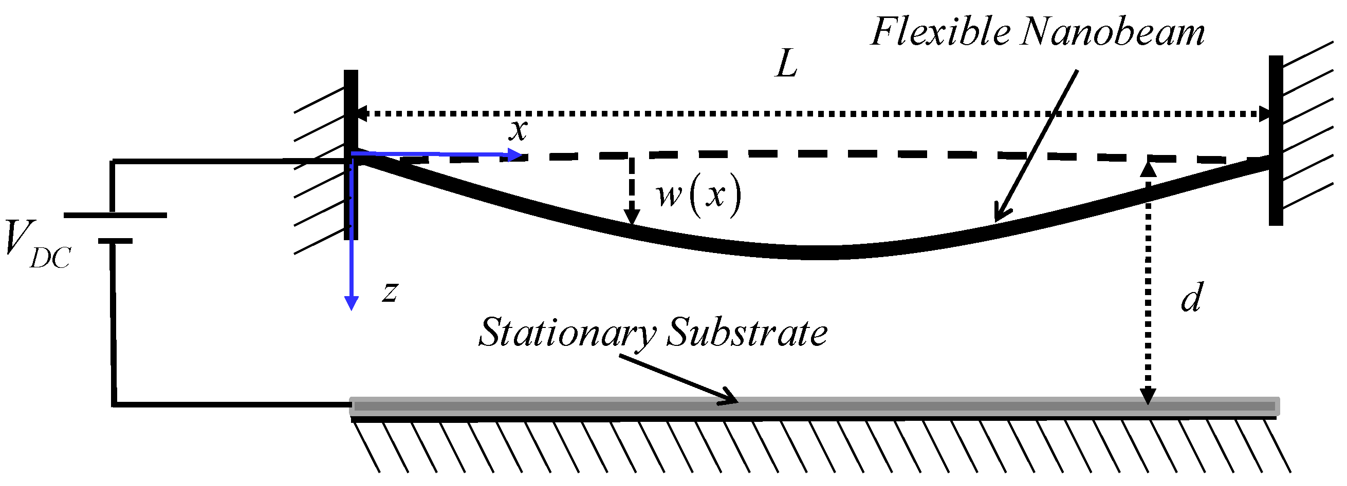
We consider here an isotropic clamped-clamped nanobeam of length
L, a uniform rectangular cross-section area of
A =
bh where
b is the beam width,
h its respective thickness, an effective Young’s modulus
E, an area moment of inertia
I = (
bh3)/12 and with an initial gap size between the flexible beam and its respective grounded actuating electrode of
d, as shown in
Figure 1. The governing differential static equation of motion of the nanobeam resulting bending deflection
under the influence of the electrostatic, as well as the intermolecular force can be written as follows [
10]:
where
symbolizes the actuating electrostatic force per unit length including the first order fringing fields effect,
represents the mid-plane stretching effect and the
term denotes the intermolecular forces. All these forces can be written respectively as follows [
10,
12]:
where
ε = 8.854 × 10
−12 F/
m is the air permittivity,
is the applied actuating
DC voltage across the nanobeam and its stationary substrate,
H is the Hamaker constant defined for a van der Waals (vdW) body-body interaction with values in the range of 10
−19 J [
21],
c = 3 × 10
8 m/s is the speed of light and
ħ = 1.055 × 10
−34 J
−s is Planck’s constant.
In the below, we will consider two cases: one with only the van der Waals force; and the second case will treat the nanobeam under the Casmir force.
2.1. First Case: van der Waals Force Only ( and )
In this case, we assume that the intermolecular forces are the van der Waals force only. Therefore, Equation (1) can be written as [
22,
23]:
Next and for convenience, we introduce the following non-dimensional parameters (
and
) to normalize the above equation of motion. Hence, and after dropping the hats, Equation (3) can be expressed in a nondimensionalized form as follows [
22,
23]:
where the above introduced nondimensional coefficients are given as follows:
Next, Equation (4) can be rewritten as [
23]:
Numerous methods can be used to numerically solve the above nonlinear equation: such as the finite-element method [
24], the finite-difference method [
25], the shooting method [
26,
27], the differential-quadrature method [
27], etc., which are all considered to be computationally expensive and in some cases unstable since some rely on initial guesses. In this investigation, we propose to use Galerkin-based reduced-order modeling that transforms the above nonlinear governing differential equation into a nonlinear algebraic equation system (considering only static DC load). Assuming now the Galerkin-based modal discretization technique [
28,
29], the nanobeam deflection solution of the above Equation (6) can be written as follows:
where
N is the assumed number of modes in the discretization method,
ki are unknown constant coefficients and
denote the beam modal functions satisfying the doubly-clamped boundary conditions at
x = 0 and
x = 1. Substituting Equation (7) into Equation (6), we get the following discretized equation:
Subsequently, multiplying both sides of Equation (8) with a modal function
and integrating with respect to
x in 0–1, we obtain:
Based on the below normality conditions [
30] of the modal functions
,
Equation (9) can be re-written as:
Next and assuming only one mode approximation (
N = 1), Equation (11) can be simplified to the following form:
The normalized first modal frequency and its corresponding normalized mode shape function considering a doubly-clamped beam configuration are given respectively as [
30]:
Computing numerically all the integrations in Equation (12), we get the following nonlinear algebraic equation function of the unknown constant coefficient
k1:
2.2. Second Case: Casimir Force Only ( and )
In this sub-section, we only consider the intermolecular effect of the Casimir force; therefore, Equations (1) and (2) can be written in normalized form as follows:
where, the nondimensional coefficient
is equal to
.
Next, and following the same steps (Equations (6) to (13)) as in the first case, assuming only one mode in Galerkin’s discretization technique and integrating numerically all the integrals, we get the following nonlinear algebraic equation function of the unknown constant coefficient
k1:
The derived two algebraic equations for the case of van der Waals attraction as the only intermolecular force, Equation (14), and for the case of Casimir force, Equation (16), are both nonlinear functions of the unknown coefficient . In addition both equations are related to the electric force coefficient (), the fringing fields effect (), the mid-plane stretching parameter () and the intermolecular forces ( for the first case and for the second case). Therefore, these equations will be subsequently used in the following section to compute the nanobeam pull-in design parameters, as well as to derive general closed-form expressions for the pull-in parameters under the influence of the considered intermolecular forces. Finally, it is worth mentioning that because the above expressions, Equations (14) and (16), are respectively the sixth and seventh order polynomial function of P1, only one solution in both cases has been found to be real and, hence, as the unique physical solution of the equilibrium deflection of the nanobeam.
3. Results and Discussion
In this section, the effects of each individual intermolecular force (i.e., the van der Waals and Casimir attraction forces, respectively) on the nanobeam deflection and pull-in instability are examined, and then general closed-form expressions for the maximum nanobeam detaching length and its respective minimum gap spacing are derived assuming zero DC load. Then, the effects of the intermolecular forces and mid-plane stretching parameters on the critical pull-in parameters are considered, and the corresponding closed-form pull-in expressions are presented. Finally, all the derived closed-form expressions are to be compared and validated with the other published results from the recent literature.
3.1. Closed-Form Solutions for the Detachment Length and Its Respective Minimum Gap Size for an Un-Actuated Nanobeam
As mentioned earlier in the introductory part of this work, in the case of the nanobeam with a small gap size, the intermolecular forces become significantly dominant over the elastic restoring forces of the nano-actuator, resulting in an earlier stiction (collapse) even without assuming any electrical actuating potential yet. Hence, it is imperative for NEMS designers to be aware of these critical dimensions as a function of the assumed maximum designed nanobeam length and minimum actuator gap size of the freestanding nanobeam-based NEMS device.
Let us first consider the effect of van der Waals forces only and with zero DC load (i.e.,
and
in Equation (14)). The resulting polynomial expression is numerically solved for various values of the van der Waal parameter
. The parameter
is assumed to vary from 0–50, and the corresponding real root (physical solution) of the polynomial expression is computed while iterating the
parameter. The iteration process is carried out until a critical value of
, denoted by
, starting from which the physical deflection of the nanobeam becomes an imaginary root, is achieved (as
≈ 48.6). The corresponding critical maximum nanobeam deflection is calculated to be equal to ≈0.309. Therefore,
, from which we can derive the expression of the maximum possible nanobeam detachment length and its respective minimum gap size respectively as follows:
Next and similarly as was done above for the case of the van der Waals attractive force, let us now consider the effect of the Casimir force only while neglecting both the electrostatic DC and the nonlinear mid-plane stretching effect (i.e.,
and
in Equation (16)). The resulting polynomial expression is then mathematically solved assuming various values of the Casimir force parameter
. This normalized parameter is iteratively varied from 0–50, and the unique real root (the physical solution) of the nonlinear equation is calculated. Accordingly, a critical value
from which the calculated physical solution becomes imaginary was found to be equal to ≈37.86. Its corresponding nanobeam critical maximum deflection is obtained to be equal to ≈0.249. Then, we can compute from Equation (15) that
, from which we can derive analytical expressions of both the maximum possible nanobeam detachment length and its respective minimum gap size respectively as follows:
The above computed analytical expressions, Equations (17) and (18), can be used to properly design appropriate guidelines for the corresponding maximum length for a given gap size and correspondingly a suitable minimum gap size for a given length for a doubly-clamped nanobeam-based NEMS device.
3.2. Comparison with the Literature Assuming an Un-Actuated Nanobeam
In the below, the above computed analytical expressions will be compared with other previously published results for validation purposes.
Table 1 and
Table 2 summarize the comparison of the calculated critical values for the normalized van der Waals parameter (
) and Casimir parameter (
), respectively, and their corresponding maximum reachable nanobeam deflections with other available results in the literature [
11,
12,
14].
Table 1 clearly shows that the critical value of the
parameter obtained using the present work does not agree well with the results of [
11,
12]. Nonetheless,
Table 2 indicates that the critical value of the
parameter agrees with the cited reference [
14], but with a minor discrepancy that can be attributed to the single mode approximation assumed in the above analysis. However, the proposed methodology is purely analytical and provides simpler expressions in predicting properly and quickly the threshold limits for the cited basic design parameters and therefore better and successful design with no possibility of damage/collapse of these nanobeams during their fabrication process.
Afterward, an additional comparison is carried out in
Table 3. In the table is the comparison of the outcomes of both Equations (17) and (18) in calculating both the maximum possible nanobeam detachment length and its respective minimum gap size respectively with the reported results of [
15]. A doubly-clamped nanobeam with modulus of elasticity
E = 176 GPa, cross-sectional area
A = 2.96 × 10
−19 nm
2, thickness
h = 3.5 nm and width
b = 18 nm is assumed.
In the last part of this comparison sub-section, we propose to add the mid-plane stretching effect and compare again the calculated critical values of the van der Waals
and Casimir
parameters for un-actuated doubly-clamped nanobeams, using Equations (14) and (16) correspondingly. It is clearly demonstrated in
Table 4 that as the mid-plane stretching parameter
increases, the values of both critical parameters
and
also increase considerably. The reason behind this is that the mid-plane stretching increases the overall stiffness of the nanobeam (i.e., its resulting restoring force) that in turn makes the nanostructure harder (hardening behavior); hence, it can withstand higher intermolecular forces before collapsing. The values obtained through the present analytical/numerical approach are in acceptable agreement with the reported numerical, but non-closed-form solutions of [
10], as can be perceived in
Table 4.
3.3. Closed-Form Solutions for the Critical Pull-In Voltage for an Actuated Nanobeam
So far, we have considered only the case of an un-actuated nanobeam (zero DC electrostatic load), and we subsequently investigated the nanobeam collapse problem governed by only the intermolecular van der Waals and Casimir forces. In this sub-section, the effect of the applied DC load will be investigated. Equations (14) and (16) are used to obtain the closed-form expressions for the pull-in parameter and its corresponding nanobeam deflection in the presence of the intermolecular forces. The method of identifying the pull-in threshold value is to iterate on the forcing parameter with a reasonable step size and check its value at which the feasible and real solution of the polynomial of k1 becomes imaginary and the system becomes unstable, hence undergoing the pull-in structural instability.
First, the electric fringing field and intermolecular force effects are neglected (
) in Equations (14) and (16), and the resulting pull-in parameter (
) values are compared with the results of [
30]. Both Equations (14) and (16) provide a pull-in parameter of ≈66.58. In [
30], this parameter value was numerically calculated to be equal to 70, and the comparison is satisfactory.
Next, we propose to investigate, as done before, two distinct cases for getting the closed-form expressions of the pull-in parameter under the influence of the van der Waals and Casimir forces, respectively.
3.3.1. First Case: Van der Waals Force Only ( and )
√ Case with the fringing-field effect and without the mid-plane stretching effect:
First, the mid-plane stretching is neglected and the electric fringing field effect is incorporated in the below closed-form analytical expression. The procedure can be summarized as follows: assuming a different range of values of the van der Waals parameter (
) ranging from 0–50 along with the electric fringing field parameter (
) ranging from 0–1, Equation (14) numerically and iteratively solved the physical and real solution
k1, which becomes imaginary. Then, and for each corresponding
and
value, the corresponding threshold pull-in parameter value of
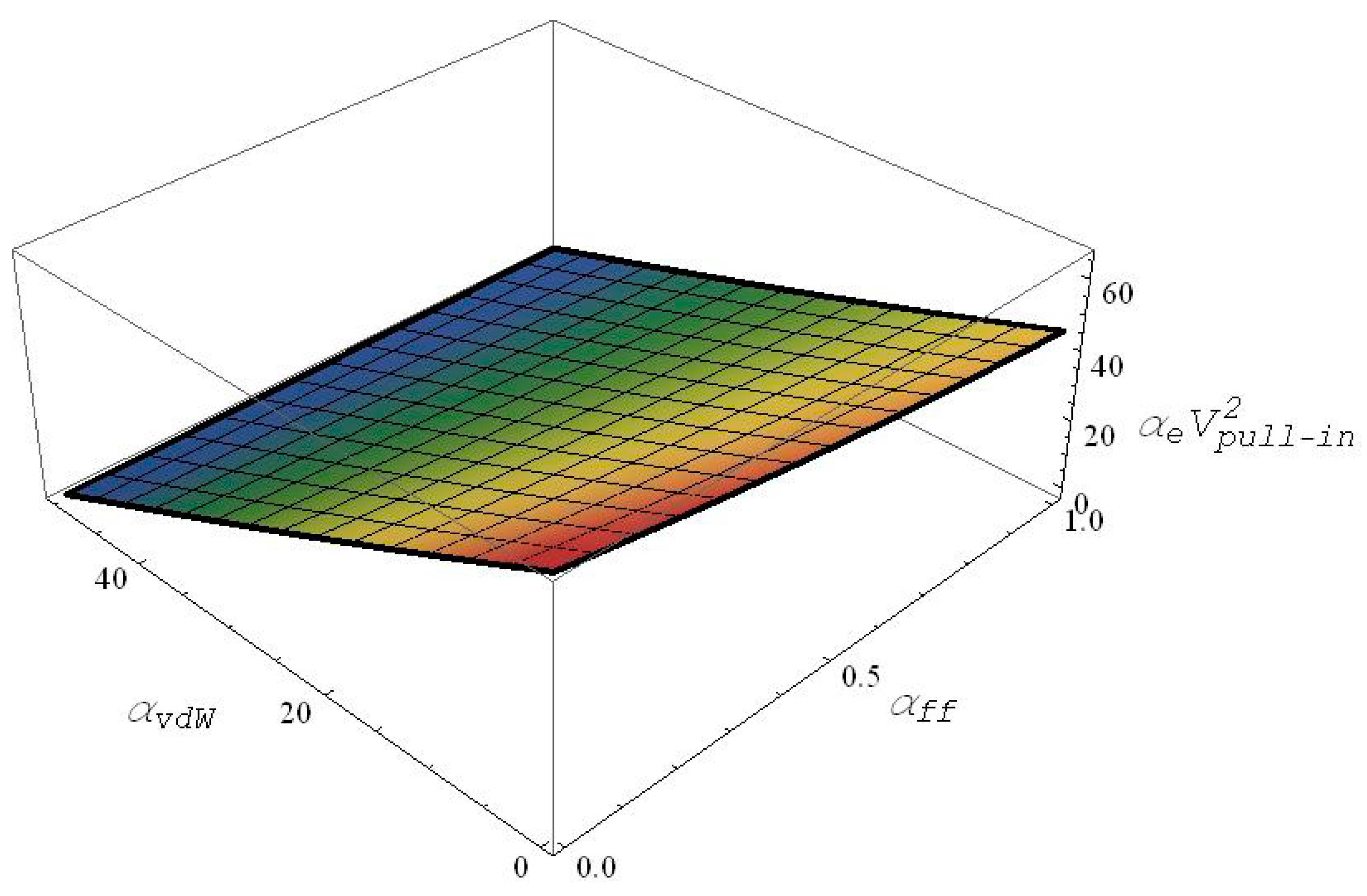
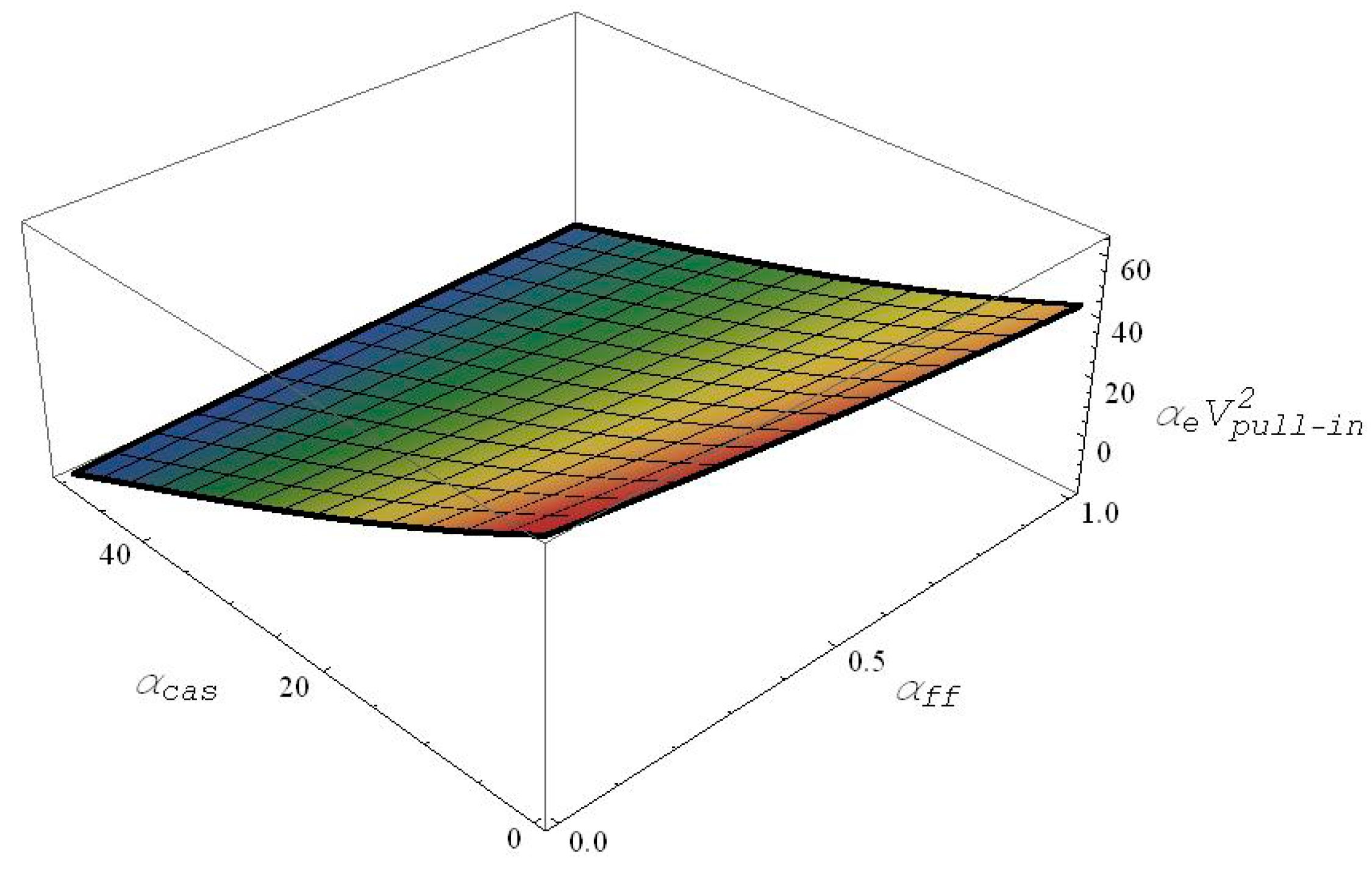
is prescribed. Accordingly, a 3D table is constructed correlating the values of the pull-in, van der Waals and electric fringing field parameters all together. The table is first suitably curve fitted with a third order polynomial using the MATLAB curve fitting toolbox as shown in Equation (19), with a calculated RMS error of 0.03, and the outcome equation is then platted as shown in
Figure 2.
As the pull-in parameter in Equation (23) is a function of both
and
, the 3D plot shown in
Figure 2 is essentially a nonlinear plane. As expected, with the increase in both the gap to width ratio, i.e., the electric fringing field parameter (
) in addition to the van der Waals parameter, the pull-in parameter reduces drastically.
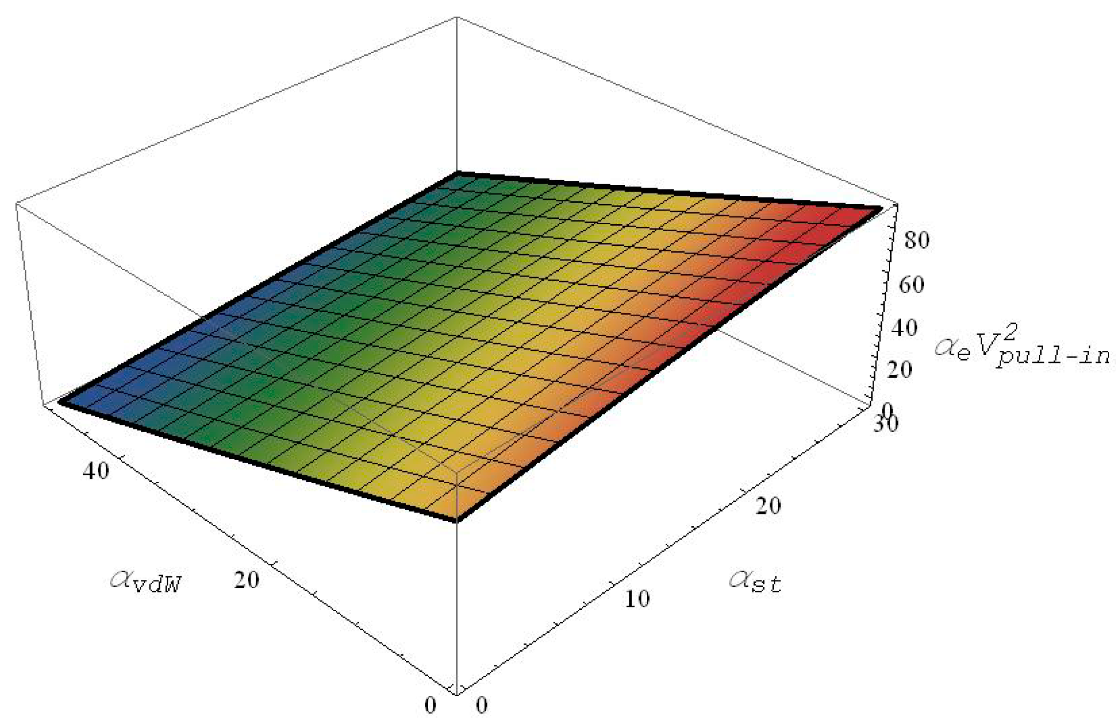
√ Case with the mid-plane stretching effect and without the fringing-field effect:
Next, the fringing-field effect is neglected, whereas the mid-plane stretching effect is varied in the presence of the van der Waals effect. Similarly as was done in the previous sub-section, a 3D table is constructed correlating the values of the pull-in, van der Waals and mid-plane stretching parameters all together. The table is then curve fitted with a third order polynomial using the MATLAB curve fitting toolbox as shown in Equation (20), with a calculated RMS error of 0.02, and the outcome equation is then platted as shown in
Figure 3.
As the pull-in parameter in Equation (23) is a function of both
and
, the 3D plot shown in
Figure 3 is basically a nonlinear plane. It can also be seen from the figure that an increase in the van der Waals parameter decreases the pull-in values; however, an increase in the mid-plane stretching parameter increases the pull-in values considerably.
3.3.2. Second Case: Casimir Force Only ( and )
Here, the pull-in parameter analytical expressions are derived considering the effect of Casimir forces only.
√ Case with the fringing-field effect and without the mid-plane stretching effect:
Next, the fringing-field effect is varied from 0–1, whereas the mid-plane stretching effect is neglected in the presence of the Casimir force effect. Similarly as was done in the previous sub-sections on the van der Waal force case, a 3D table is constructed correlating values of the pull-in, Casimir and the fringing electric field parameters all together. The table is then curve fitted with a third order polynomial using the MATLAB curve fitting toolbox as shown in Equation (21), with a calculated RMS error of 0.039, and the outcome equation is then platted as shown in
Figure 4.
As seen from
Figure 4, and as expected, the increase in both the gap to width ratio (i.e., the fringing field parameter), as well as the Casimir parameter both cause a significant decrease of the pull-in parameter.
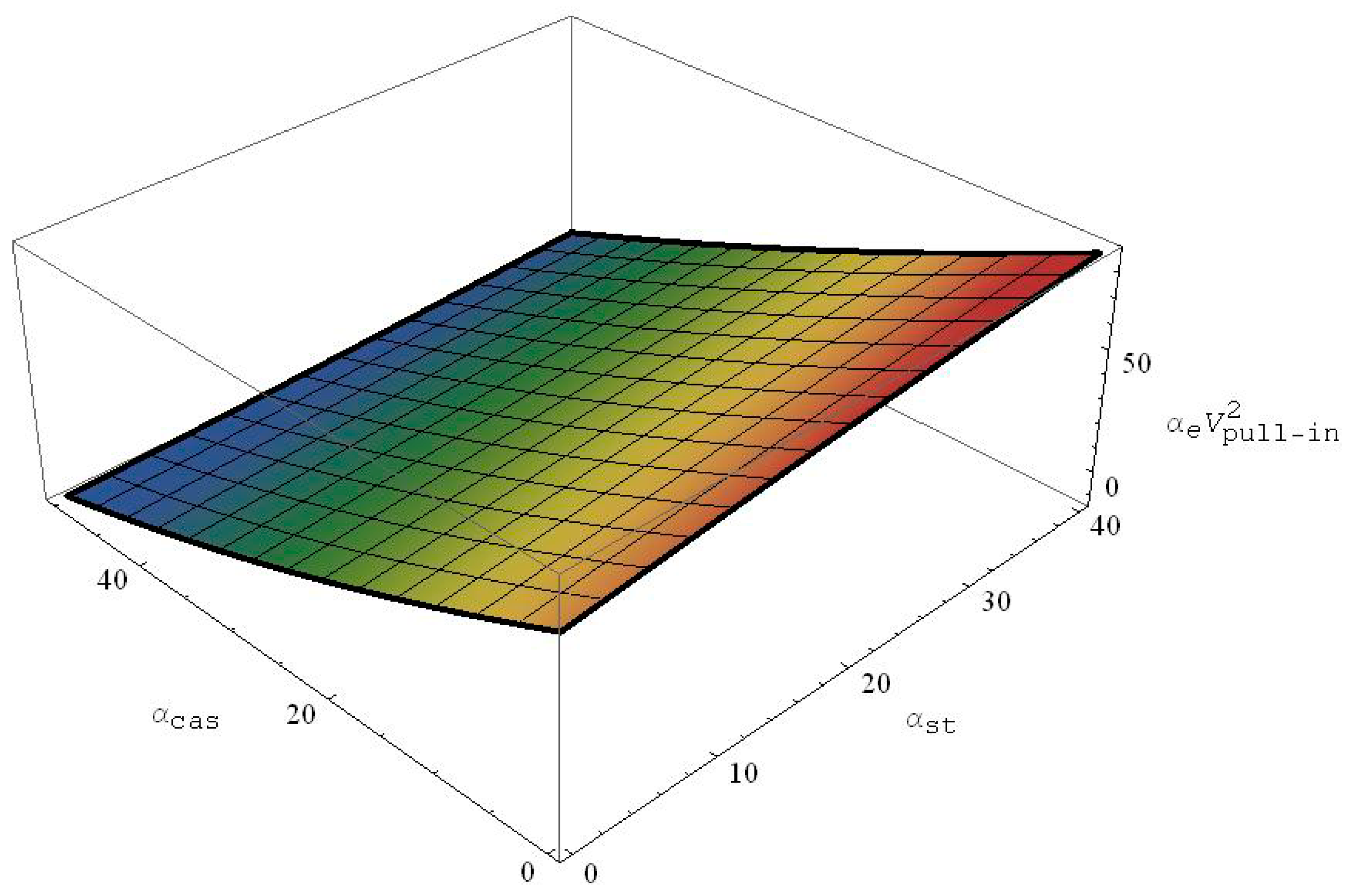
√ Case with the mid-plane stretching effect and without the fringing-field effect:
Next, the electric fringing effect is neglected, and the mid-plane stretching effect is investigated in the presence of Casimir effect. Similarly as was done in the previous sub-section, a 3D table is constructed correlating the values of the pull-in, van der Waals and mid-plane stretching parameters all together. The table is then curve fitted with a third order polynomial using the MATLAB curve fitting toolbox as shown in Equation (22), with a calculated RMS error of 0.03, and the outcome equation is then platted as shown in
Figure 5.
It is apparent from
Figure 5 that any assumed increase of the Casimir parameter decreases the pull-in parameters, whereas any assumed increase in the mid-plane stretching effect increases the pull-in values considerably.
3.4. Comparison with the Literature of the Pull-In Parameter in Presence of Van der Waals and Casimir Forces
In this last sub-section of the results analysis, all the above computed analytical expressions of the pull-in parameters will be compared with other previously published results for validation purposes.
Table 5,
Table 6,
Table 7 and
Table 8 summarize the comparison for both cases while assuming a non-zero van der Waals parameter and also when assuming a non-zero Casimir parameter.
Table 5 displays a quantitative comparison of the calculated pull-in parameters using Equation (21) respectively with the reported results of [
14]. In the table, various Casimir parameters
are selected, for two different fringing field parameters (i.e.,
and 1), and neglecting mid-plane stretching (
). The table shows that the pull-in parameter values obtained analytically are slightly lower than the numerical value of [
14]. This small discrepancy could be attributed to the numerical approximations used in [
14] and to the negligence of the higher-order modes in the present work.
Next, the same pull-in parameters will be computed while the mid-plane stretching is assumed to be non-zero, neglecting the fringing field effect, and considering both the influences of the van der Waals and of the Casimir forces effects. The results are then compared with the outcomes [
10] and summarized in
Table 6 and
Table 7, respectively. It can again be noticed from both tables that the present analytical approach slightly underestimates the pull-in voltage parameters as compared to the published values in [
11], which can be over attributed to the one-mode approximation we assumed in out analytical/numerical approach.
Finally,
Table 8 delivers a quantitative comparison of pull-in voltage (in Volts) with and without including the mid-plane stretching effect and then compared to the results of [
12]. The comparison was performed assuming a doubly-clamped nanobeam with an initial gap size of
d = 20 nm, a thickness
h = 3.5 nm, a width of
b = 18 nm, a Young’s modulus of elasticity of
E = 166 GPa and three assumed beam lengths of
L = 130 nm,
L = 150 nm and
L = 180 nm.
Table 8 first shows that the comparison with the results of [
12] has an acceptable agreement. Second, it is noticed from the same comparison table that neglecting the mid-plane stretching effect will lead to a significant difference in the pull-in voltage estimation. It is also evident from the same table that the pull-in voltages obtained through our proposed approach while incorporating both effects of the electric fringing field and the mid-plane stretching agree well in both the van der Waals and Casimir force cases. For the case of Casimir force only, the comparison is even more in agreement as compared with the outcomes when considering only van der Waals force. This implies that for given beam dimensions and a 20-nm initial gap size, the intermolecular effects can be properly modeled by considering the Casimir attraction force rather than the van der Waals force. Therefore, this last assumption can yet serve as quick design guidelines in the NEMS community.
4. Conclusions
The present work proposes simple and yet generalized analytical expressions for determining doubly-clamped electrically-actuated nanobeam-based NEMS actuator design limits for various critical design parameters along with the appropriate static pull-in parameters under the influence of the mid-plane stretching, the electric fringing field, the van der Waals and the Casimir forces. Firstly, the coupled electromechanical problem of the nano-actuator is proposed and discretized using the so-called Galerkin modal discretization technique. In the subsequent steps, the resulting integrals and the higher order polynomials are solved numerically to get closed-form expressions for the maximum nanobeam detachment length, its respective minimum gap size and the pull-in parameter expressions when considering only the first mode of the nanobeam deflection. It has been further observed through extensive examinations that the incorporation of the intermolecular forces and the electric fringing field effect result in a significant decrease in the pull-in voltage estimation, whereas the presence of the mid-plane stretching parameter shows contrary effects. Finally, the derived expressions and results were all compared and validated quantitatively with other reported literature showing reasonable agreement.
The main advantage of the proposed approach in this work is that the derived closed-form analytical expressions do not include any complicated terms or complex mathematical operations unlike in the reported literature; hence, it can be willingly used by NEMS designers for quick and closer estimation of critical design parameters to avoid any unprecedented structural damage during fabrication or operation. The derived analytical expressions were presented to produce fair outcomes for most common design parameters of nanobeam-based actuators. For nanobeams with a higher stretching effect, it was found that these expressions yield less exact approximations due to the limitations of the single-mode approximation. In such cases, a multi-mode-based numerical model is to be implemented for more accurate results.
Finally, it is worth mentioning that this investigation treated both intermolecular forces independently. Nonetheless, the obtained analytical expression can be further coupled to account for the joint effect of both attractive forces. Consequently, the results could be further improved and would be more comprehensive for scenarios where the two forces are of comparable strength.


