Article

Examination of High-Torque Sandwich-Type Spherical Ultrasonic Motor Using with High-Power Multimode Annular Vibrating Stator

1
Graduate School of Engineering, Muroran Institute of Technology, 27-1, Mizumoto, Muroran, Hokkaido 050-8585, Japan
2
Department of Information and Communication Engineering, Tohoku Institute of Technology, Sendai, Miyagi 982-8577, Japan
*
Authors to whom correspondence should be addressed.
Actuators 2018, 7(1), 8; https://doi.org/10.3390/act7010008
Submission received: 5 January 2018 / Revised: 13 February 2018 / Accepted: 20 February 2018 / Published: 27 February 2018
(This article belongs to the Special Issue Piezoelectric Actuators 2018)

Abstract

:
Spherical ultrasonic motors (SUSMs) that can operate with multiple degrees of freedom (MDOF) using only a single stator have high holding torque and high torque at low speed, which makes reduction gearing unnecessary. The simple structure of MDOF-SUSMs makes them useful as compact actuators, but their development is still insufficient for applications such as joints of humanoid robots and other systems that require MDOF and high torque. To increase the torque of a sandwich-type MDOF-SUSM, we have not only made the vibrating stator and spherical rotor larger but also improved the structure using three design concepts: (1) increasing the strength of all three vibration modes using multilayered piezoelectric actuators (MPAs) embedded in the stator, (2) enhancing the rigidity of the friction driving portion of the stator for transmitting more vibration force to the friction-driven rotor surface, and (3) making the support mechanism more stable. An MDOF-SUSM prototype was tested, and the maximum torques of rotation around the X(Y)-axis and Z-axis were measured as 1.48 N∙m and 2.05 N∙m, respectively. Moreover, the values for torque per unit weight of the stator were obtained as 0.87 N∙m/kg for the X(Y)-axis and 1.20 N∙m/kg for the Z-axis. These are larger than values reported for any other sandwich-type MDOF-SUSM of which we are aware. Hence, the new design concepts were shown to be effective for increasing torque. In addition, we measured the transient response and calculated the load characteristics of rotation around the rotor’s three orthogonal axes.

1. Introduction

In recent years, developments in robot technology have increased the demand for downsized and simplified actuator systems. The actuator system with multiple degrees of freedom (MDOF) is one way to meet this demand. Spherical motors that can operate with MDOF using only a single stator were proposed [1,2,3,4,5], and such systems are effective for downsizing. MDOF motion is often required under conditions of low speed with large torque. However, a spherical electromagnetic motor (SEMM) has characteristics of low torque at high speed [6,7,8,9,10,11,12,13]. In contrast, an ultrasonic motor has the potential to be an MDOF drive source due to higher performance with respect to a SEMM; it has high torque at low speed, high holding torque, and no need for reduction gearing. For these reasons, MDOF ultrasonic motors and MDOF spherical ultrasonic motors (SUSMs) have been studied [14,15,16,17,18,19,20,21,22,23,24,25,26,27].
The authors previously reported MDOF-SUSMs using annular vibrating stators that can excite multiple vibration modes [28,29,30,31]. Our results showed that the sandwich-type MDOF-SUSM is effective for increasing torque despite its compact size [28,29]. The sandwich structure refers to a spherical rotor held between two annular vibrating stators. The MDOF motion of the rotor can be realized even if only one stator is used with a rotor support mechanism, so two active stators increases the torque for all three rotational axes. This simple structure has both a rotor support and a preload mechanism.
Although the MDOF-SUSM is useful as a compact actuator, it is still insufficient in applications such as larger joints of a humanoid robot and other systems that require both MDOF and high torque. For a robot manipulator, which is the expected application of the SUSM, a shoulder joint requires a motor with high torque and high rigidity because some wrist and elbow motors apply a load to the shoulder joint motor. Most MDOF-SUSMs are useful for low-load applications, such as small robotic wrist joints and hands, because of their high torque per unit weight. However, their maximum torques range up to only about 200 mN∙m [14,15,20,21,22,25,28,29,30,31]. These torques are insufficient for high-load applications, such as wrist and shoulder joints, because these applications require high torque of at least 10 N∙m [15]. The MDOF-SUSM simply cannot generate output torque at the same level as a same-size motor with one degree of freedom.
To make the MDOF-SUSM with annular vibrating stator previously reported [29], a thin piezoceramic (PZT) disk with divided electrodes was bonded to the surface of the stator. This excitation method has the advantage of simple structure and compact size, and it is adopted in many types of ultrasonic motors. However, the method has a disadvantage in that it generates force using the piezoelectric lateral effect, which is weak in comparison to the piezoelectric longitudinal effect. To obtain high torque, it is necessary to change the method for exciting vibration modes to a more effective method that produces higher-power excitation.
In this study, a high-torque sandwich-type MDOF-SUSM using a new annular vibrating stator with a strong excitation structure was developed based on three design concepts: (1) Stronger excitation is produced by utilizing the piezoelectric longitudinal effect of multilayered piezoelectric actuators (MPAs) having a high mechanical quality factor; (2) The rigidity of the friction driving portion of the stator is increased; (3) A more stable support mechanism is developed.
The MPAs embedded in the vibrating stator can strongly excite the three different vibration modes necessary for the stator to drive rotation. Furthermore, it is possible to suppress the attenuation of the excited vibration force by increasing the rigidity of the friction driving portion of the stator. This results in increased rotor driving force, and a further torque increase can be expected due to its capacity for higher preload. Thus, this paper describes the effectiveness of strong excitations by MPAs and the design and driving method of a new vibrating stator. Some performance characteristics of a prototype MDOF-SUSM using the new stator are reported and compared to the performance of the previous type that had a 20 mm-diameter spherical rotor [29]. Hereafter, the previous type is called the ϕ20 mm type. The obtained performance of both MDOF-SUSMs cannot be compared directly because their spherical rotors and stators have different sizes, so the torque per unit weight of stator was also determined to serve as a performance index.

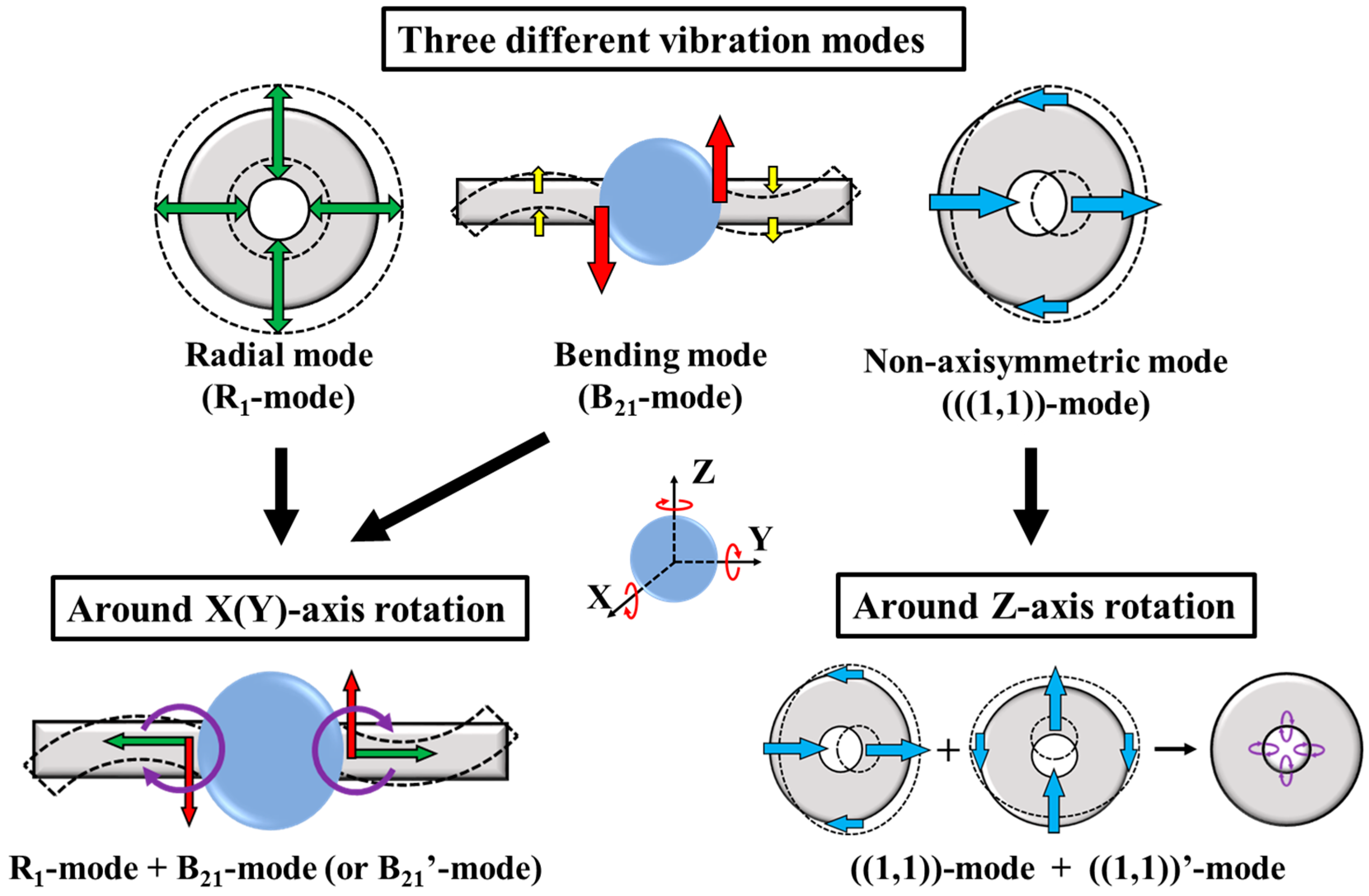
2. Operating Principle

The operating principle of the sandwich-type MDOF-SUSM is shown in Figure 1. The motor’s annular stator can independently excite three different vibration modes: the bending vibration mode (B21-mode), the radial vibration mode (R1-mode), and the non-axisymmetric vibration mode (((1,1))-mode). The B21’-mode and ((1,1))’-mode are the same-shape orthogonal modes of the B21-mode and the ((1,1))-mode, respectively. A spherical rotor can be rotated around three axes by combining two of these vibration modes.

2.1. Rotation around X(Y)-Axis

When B21-mode or B21’-mode, and R1-mode are combined, the bending vibration generates a rotation torque in the vertical plane and the radial vibration controls the friction of the contact surface between the rotor and stator. Therefore, the spherical rotor can rotate around the X(Y)-axis continuously via an elliptical displacement motion generated in the stator. The resonance frequencies of B21-mode (B21’-mode) and R1-mode need to be close to each other because the stator must simultaneously generate both vibrations with a single driving frequency.

2.2. Rotation around Z-Axis

When ((1,1))-mode and ((1,1))’-mode are excited with a phase difference of 90°, an elliptical displacement motion occurs in the Z-plane of the stator. The rotor receives a frictional rotary force and rotates around the Z-axis based on traveling-wave ultrasonic motion.

3. Construction Design and Driving Method

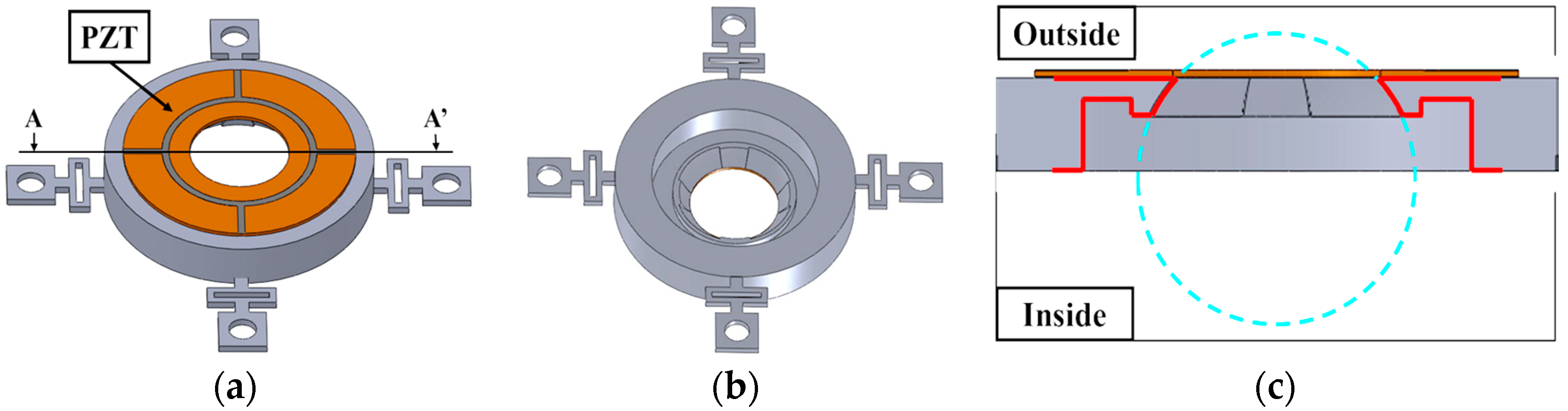
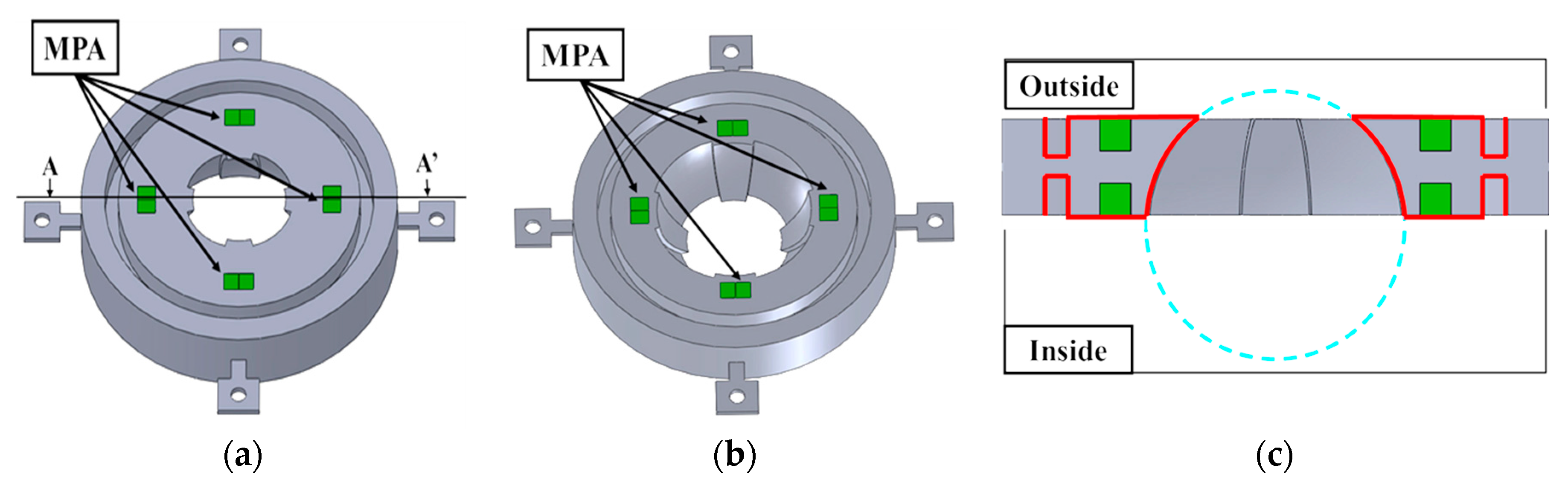
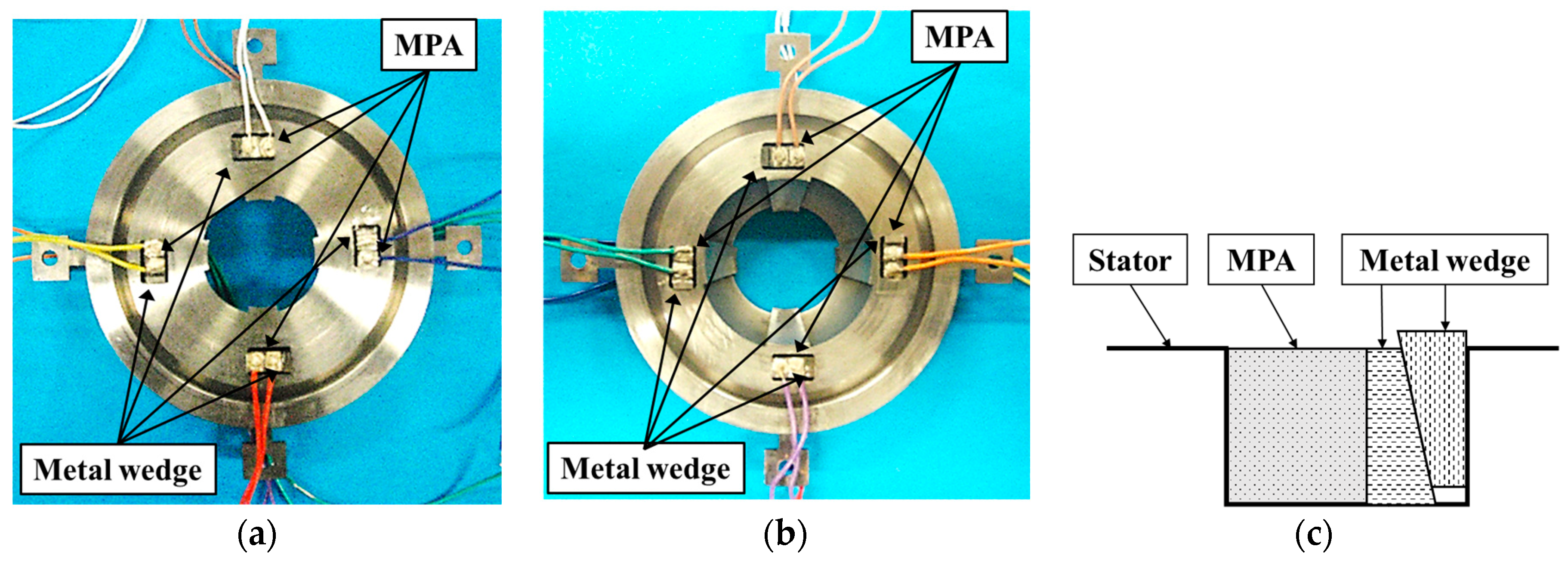
3.1. Vibrating Stator Construction

The design of the annular vibrating stator is shown in Figure 2. For strong excitation, two concepts are incorporated.
The first concept is the excitation of the stator by embedded MPAs made of hard piezoelectric material provided with a high mechanical quality factor, which has inner losses less than those of a soft material. The MPA is constructed by alternately stacking several tens to several hundreds of thin piezoelectric ceramic sheets and electrodes. The polarizations of the ceramic sheets are in the thickness direction, and they are opposite to each other. Positive and negative electrodes are connected in parallel. Hence, a high electric field is applied to each ceramic sheet, so that large force and displacement in the thickness direction are generated by applying a low voltage. The MPA was adopted after comparing the excitation performance of an MPA embedded in a vibrating bar and a PZT plate bonded to an equivalent vibrating bar. It was confirmed that the excitation by an MPA embedded in the vibrator generated a stronger excitation at low applied voltage. The details are described in Appendix A. Figure 2 shows how the MPAs are arranged and embedded in the inner and outer surfaces of the new stator. A pair of MPAs is embedded in each square hole on both surfaces.
The other concept is the increased rigidity of the friction-driving portion of the stator. The new stator design was given high structural rigidity by increasing the thickness of the inner ring of the stator, where it contacts the rotor, in comparison with the proportionate thickness of the ϕ20 mm type shown in Figure 3. This was done to suppress the attenuation of the strong excited vibration force and to increase the driving force to the rotor. The designed stator has four spherically shaped surfaces for partial but stable contact with the spherical rotor [29]. For rotation around the X(Y)-axis, the spherical contact surface has an effective portion that generates friction to rotate the rotor and a non-effective portion that produces a braking force. This is why a partial contact surface is needed.
Figure 4 shows the strain distribution of the stator in each vibration mode, as simulated by finite element analysis (FEA). We assumed the stator made of an austenitic stainless steel, SUS304 (18Cr-8Ni) based on Japan JIS standard, which was a quite popular material. The material characteristics using FEA were Young’s modulus of 197 GPa, density of 8000 kg/m3, and Poisson’s ratio of 0.33. To excite the vibration mode effectively, MPAs were arranged at large-strain portions. The dimensional parameters of the stator are shown in Figure 5. The X(Y)-axis rotation of the motor is driven by the combination of R1-mode and B21-mode or B21’-mode vibrations; therefore, their resonance frequencies were brought close each other by tuning the diameters and thicknesses of each part of the stator by modal FEA. The resonance frequencies for a range of values for each dimensional parameter are shown in Figure 6. The dimensions of the stator were determined using these simulations, which assumed a spherical rotor diameter of 50.8 mm.

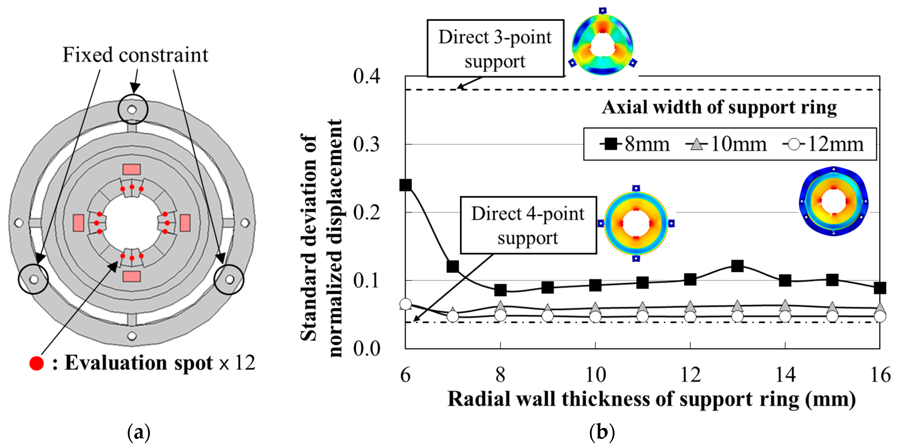
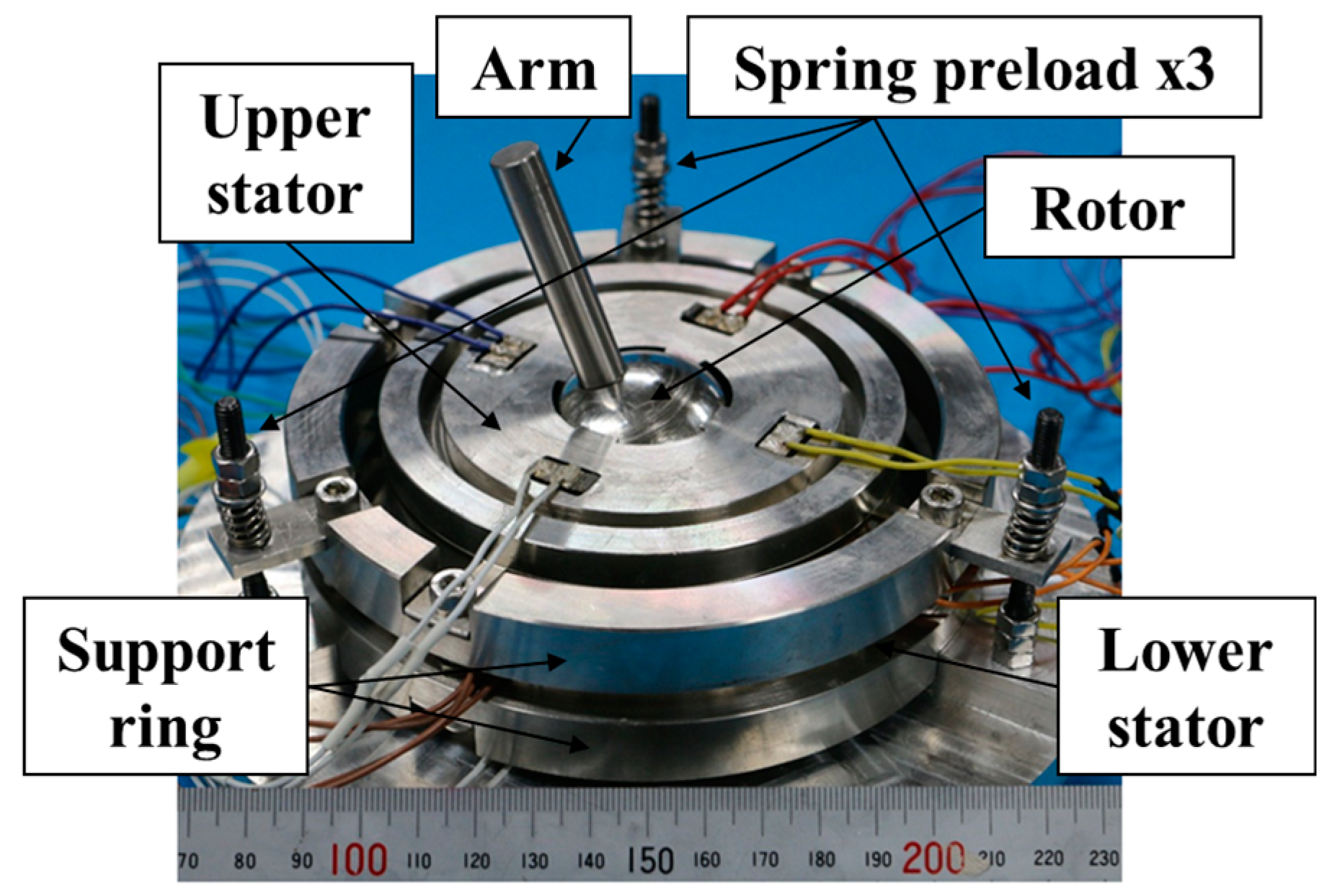
3.2. Motor Structure

The basic construction of the new MDOF-SUSM design is shown in Figure 7. The stators, spherical rotor and support rings were made of the stainless steel SUS304. To achieve high torque with strong excitation, the structural stability of the preload mechanism is important. Supporting beams of the ϕ20 mm type stator shown in Figure 3 could reduce negative effects on the vibration mode. However, such a structure was weak against the force in the preload direction, so that large preload was hardly applied. Moreover, the ϕ20 mm type stator was apt to become unstable by its own output torque. Therefore, supporting beams of the prototype stator had relatively high rigidity in preload direction and radial direction. Each stator is fixed to a support ring at four points of supporting beams. The assembled support rings are used for preload adjustment. This construction aims to provide a uniform preload and its easy setting at three points without affecting the vibration modes. Hence, the support ring was designed by tuning its outer diameter, that is, its radial wall thickness and axial width, by FEA. The forced vibration of the stator was analyzed by FEA under the condition that the certain voltage of natural frequency of R1-mode was set to MPAs. The vibration amplitudes of R1-mode at 12 evaluation spots shown in Figure 8a were calculated about each dimension of support ring. If R1-mode was affected and deformed by the support ring, the evaluation spots at the inner circumference of the stator had different vibration amplitude. If not, the vibration amplitude at all evaluation spots should be almost the same. Negative effects on the vibration mode were evaluated by calculating the standard deviation (SD) which evaluates the degree of dispersion in vibration amplitude at the evaluation spots. The distribution of displacement is unaffected by the maximum vibration amplitude due to linear analysis, even though the maximum vibration amplitudes obtained in each simulation were different. Therefore, the SD of the simulated vibration amplitude normalized with its maximum value was suitable for the evaluation. The simulation results, shown in Figure 8b, confirmed that support ring effects on the vibration modes could be reduced by adjusting the radial wall thickness to 15 mm and the axial width to 12 mm. The SDs of 0.048 and 0.039 were obtained on the stator with and without the designed support ring, respectively. Thus, the stator support ring design considered the displacement deviation, given an approximation of the resonance frequencies of the vibration modes. The FEA results for stator resonance frequency were: 21.32 kHz for B21-mode, 21.41 kHz for R1-mode, and 24.30 kHz for ((1,1))-mode.

3.3. Driving Method

The arrangement of MPAs in the new stator is shown in Figure 9. Each vibration mode is excited by two ports on opposite sides of the stator: Port A and Port B, or Port C and Port D. The vibration mode can be selected by applying a sinusoidal voltage of the appropriate phase difference to each MPA, as shown in Table 1. Moreover, rotational movement in the three axis directions is generated by combining the two vibration modes that are excited in each port, as shown in Table 2.

4. Structure and Measured Characteristics

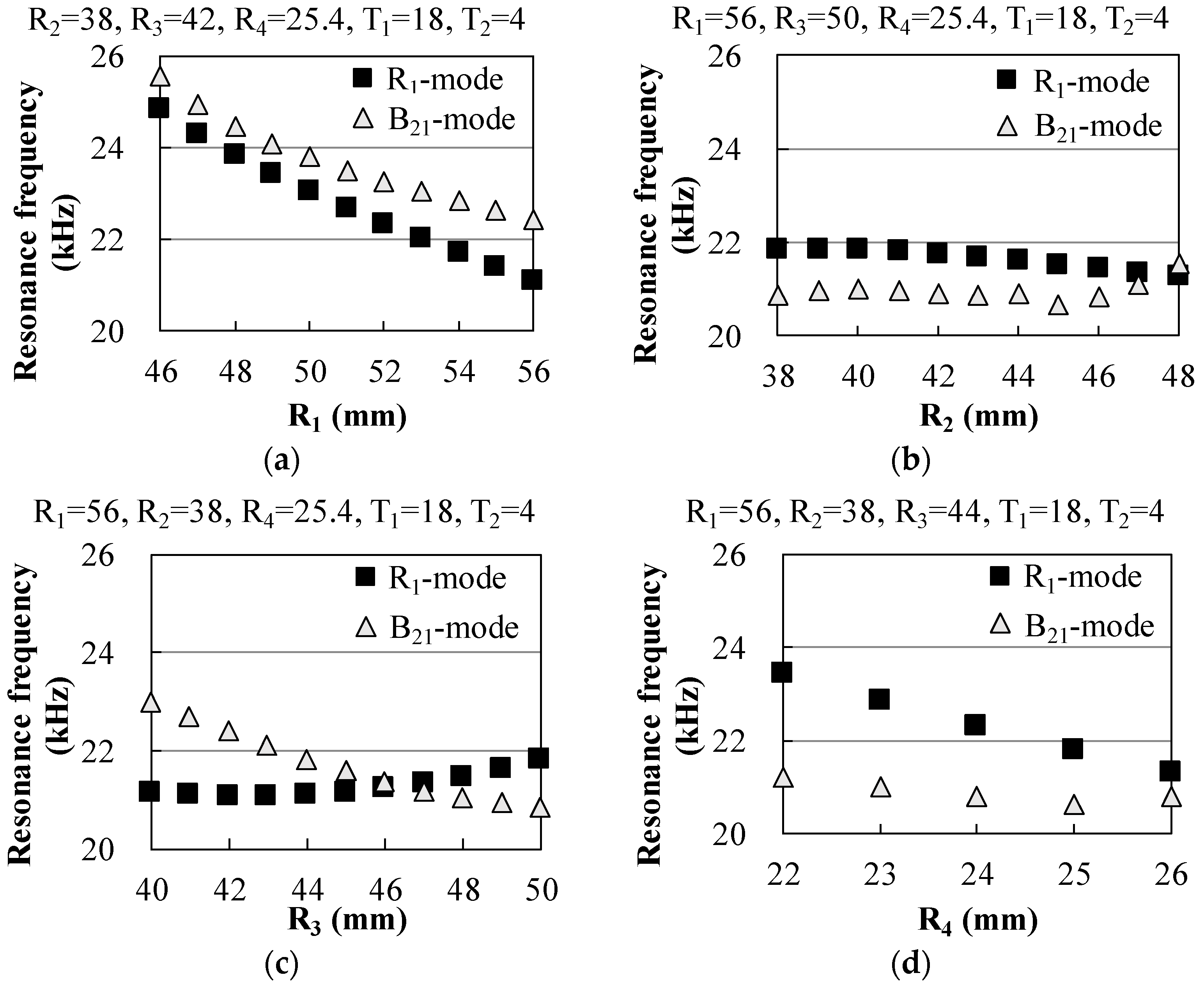
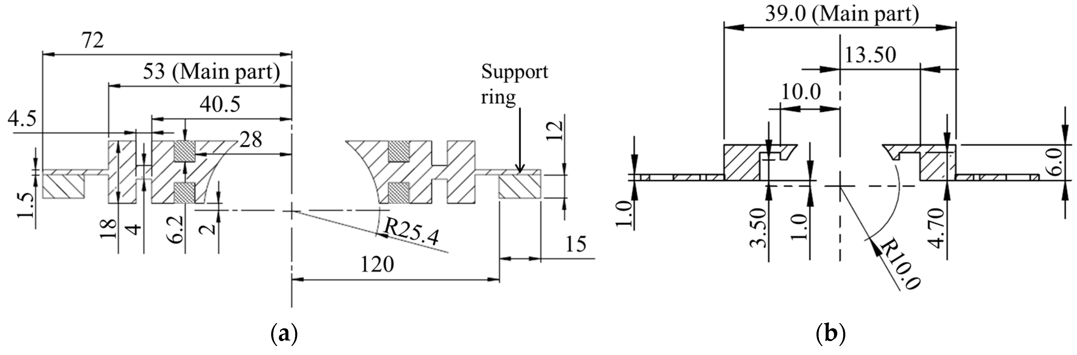
4.1. Stator Dimensions

Figure 10 shows an assembled stator for the prototype MDOF-SUSM. The MPAs were embedded into rectangular holes formed in the stator, and they were secured in the holes with metal wedges, as shown in Figure 10c. The stator dimensions were determined by FEA simulation. Figure 11a,b show dimensional drawings of designed prototype stator and the ϕ20 mm type stators, respectively. For the generation of high torque, the prototype stator was designed for a spherical rotor 50.8 mm in diameter, which is about 2.5 times larger than the rotor of the ϕ20 mm type, and the main part of the stator was about 2.7 times larger than that of the ϕ20 mm type. It is understood that the prototype stator was not simple upsizing of the ϕ20 mm type.

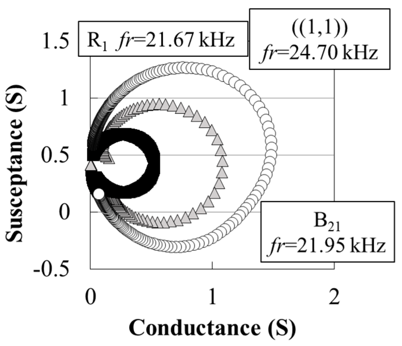
4.2. Admittance Characteristics

Figure 12 shows the admittance loops for each vibration mode of the prototype stator, as measured by an impedance analyzer. The resonance frequencies of each vibration mode were close to the results from FEA simulation. In the prototype, the dynamic admittances for B21-mode, R1-mode, and ((1,1))-mode were 1.08 S, 0.52 S, and 1.48 S, respectively. These values are very large, and a large current flow was expected. In addition, the resonance quality factors were obtained as 426 for B21-mode, 504 for R1-mode, and 301 for ((1,1))-mode. This confirmed that the prototype stator had good electrical performance despite its large and somewhat complicated structure.

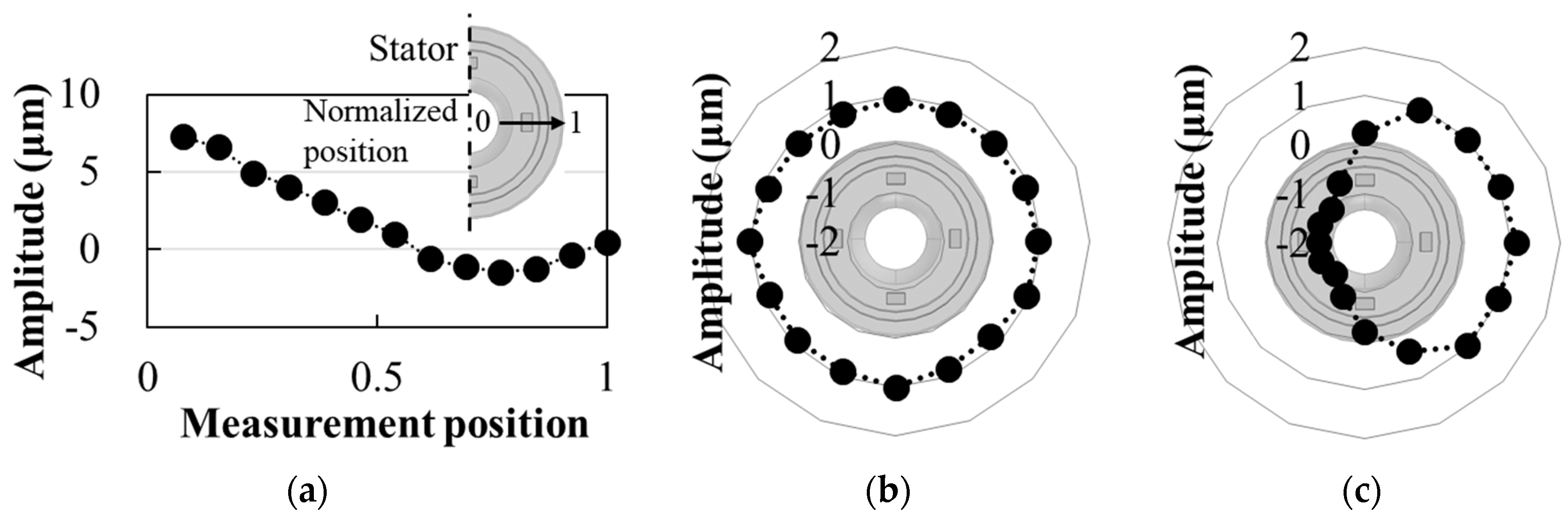
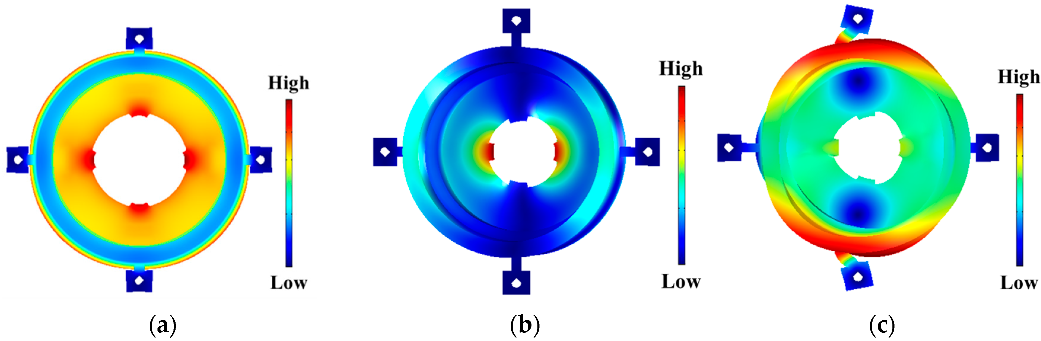
4.3. Vibration Displacement
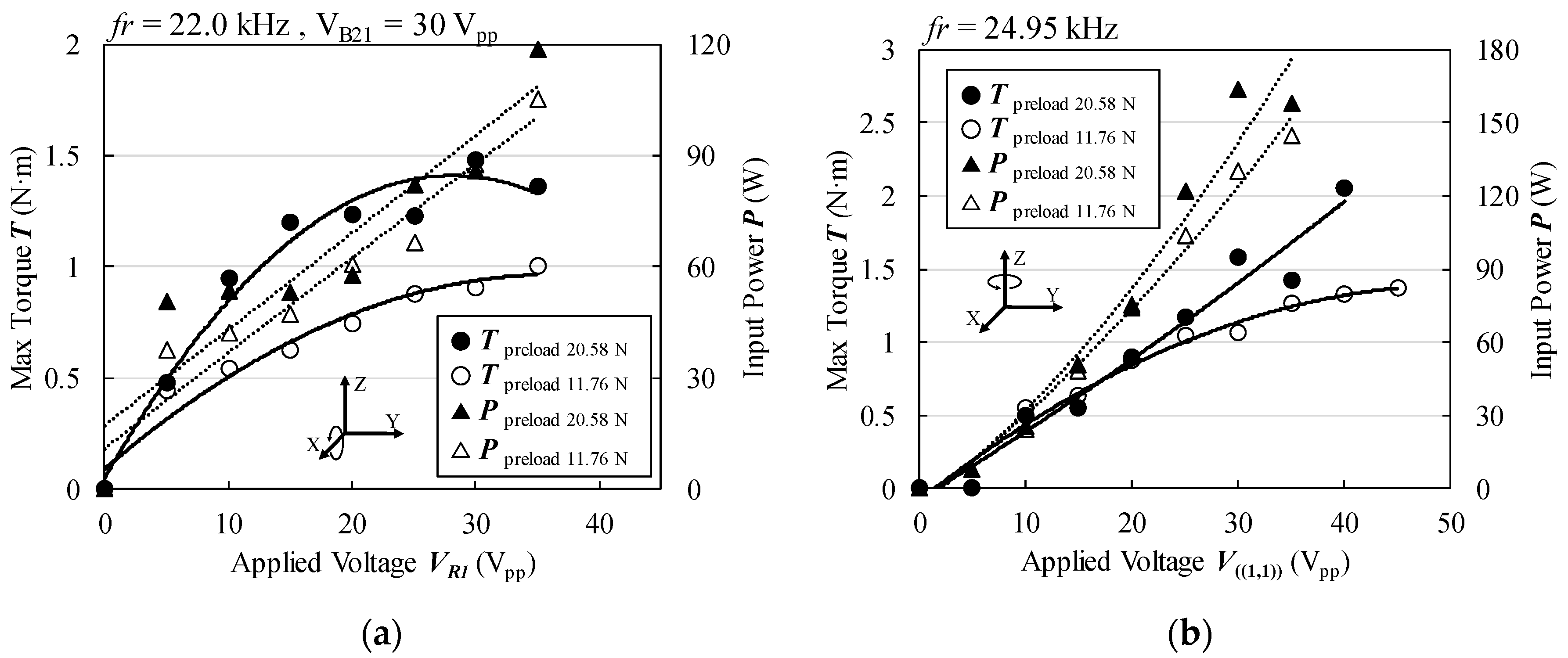
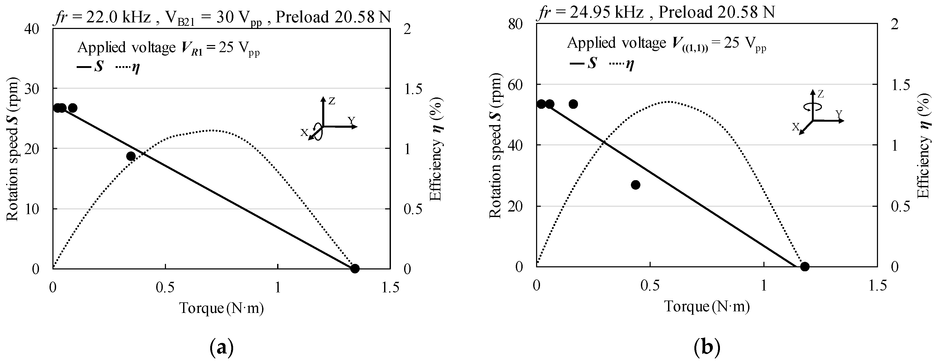
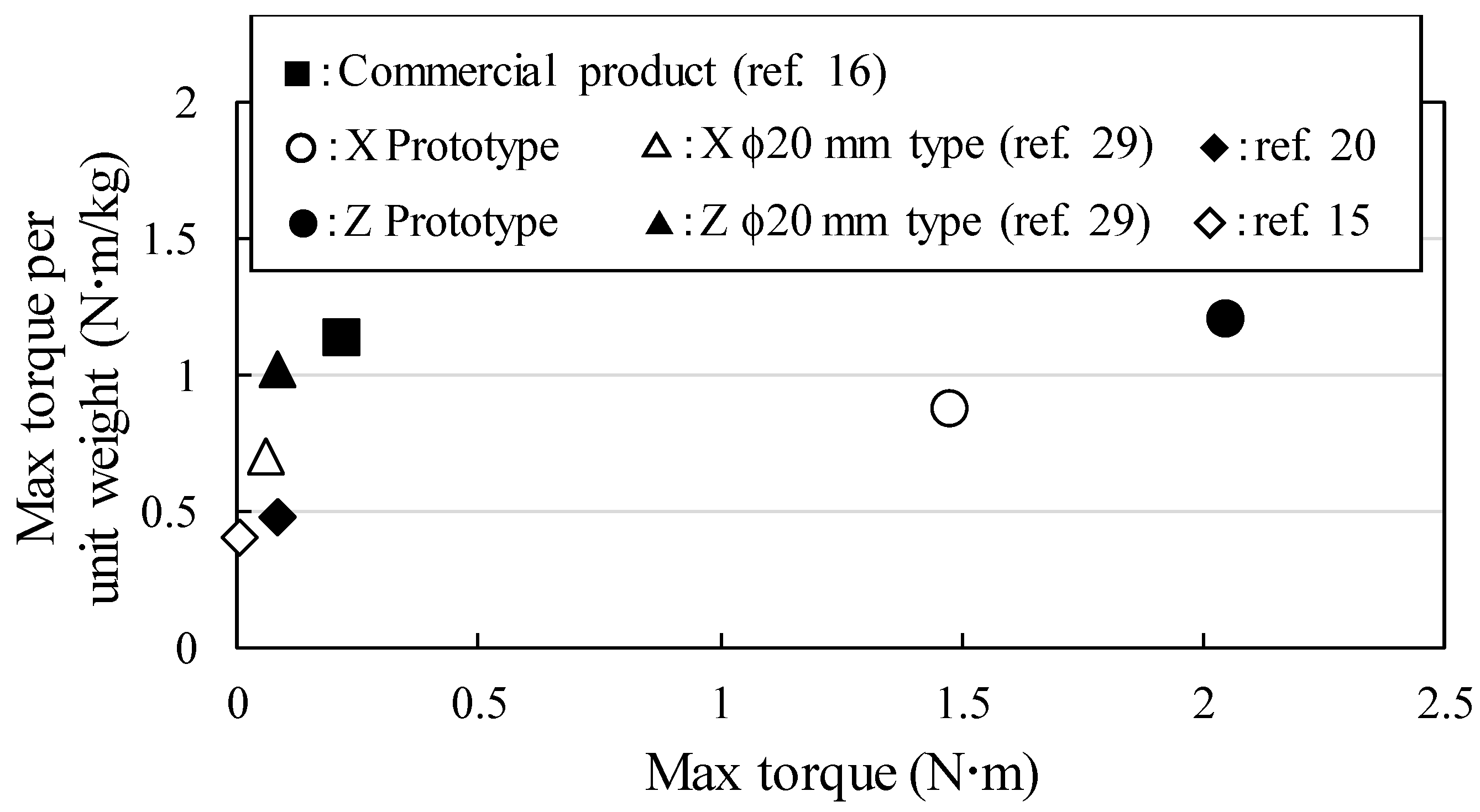
Figure 13 shows the vibration displacements on the surface of the prototype stator, as measured by a laser Doppler vibrometer (Ono Sokki, LV-1800). The measurement positions were the normalized position, which was defined in the inserted figure of Figure 13a, on the upper surface of the stator in B21-mode and the outer surface of the stator in R1-mode and ((1,1))-mode. The excitations of each vibration mode met the design objectives. At an applied voltage of 8 Vpp, a vibration amplitude of 7.27 μm was obtained in B21-mode near the point of contact between the rotor and stator. For reference, this value was about 48.5 times larger than the vibration amplitude, 0.15 μm, of the ϕ20 mm type [29]. Moreover, the maximum vibration amplitudes of R1-mode and ((1,1))-mode were about 27 times and about 28 times larger than those of the ϕ20 mm type, respectively. Hence, the embedded MPAs succeeded in generating strong excitations.

4.4. Maximum Torque

The prototype sandwich-type MDOF-SUSM is shown in Figure 14. Table 3 lists the resonance frequencies and input admittances of both stators assembled with their support rings, as measured by an impedance analyzer. The difference in the resonance frequencies of the two stators was approximately 60 Hz. The measured resonance frequencies agreed very well with the FEA simulation results. Moreover, because both stators had similar input admittances, both could be excited by the same drive frequency and applied voltage for the same level of torque generation. In the measurement of the vibration amplitude at the evaluation spots shown in Figure 8a, the SDs of 0.077 and 0.046 were obtained on the stator with the designed support ring and without it, respectively. The influence of the support ring in the measurement was larger than that in the simulation, however, its SD was still suppressed lower. Figure 15 shows the measured maximum torque and the input power for each axis rotation with respect to the voltage applied to the prototype MDOF-SUSM. The maximum torque was measured by a force gauge and an arm attached to the spherical rotor, and the input power was measured by a high-frequency power meter. The common drive frequency of the upper and lower stators was 22.0 kHz when the rotor rotated around the X(Y)-axis and 24.95 kHz when the rotor rotated around the Z-axis. The preload between the two stators was adjusted using the spring-tensioned screws that attach the support rings to each other. We confirmed that torque could be increased using the 3-point preload adjustment.
At the preload of 20.58 N, the maximum torque of rotation around X(Y)-axis had the peak value, but that around Z-axis had no peak and it was not saturated until the applied voltage of 35 Vpp. Maximum torques at applied voltages of 40 Vpp and 45 Vpp were measured to search the value of the largest maximum torque. However, those continued to increase. At those applied voltages, the value of electric current exceeded the current measuring range of the power meter used in experiment, so that data of input power was not provided. Large input power was necessary to generate large maximum torque. Most of the input power was consumed as heat loss. A temperature rise of MPA was the most intense, and the temperature at the surface of MPA rose up to around 60°C at the applied voltage of 30 Vpp with offset of 15 V and input power of around 160 W.
Table 4 compares the maximum torque and torque per unit weight of the stators of the prototype MDOF-SUSM and the ϕ20 mm type [29]. The prototype MDOF-SUSM achieved an obvious increase in torque. The maximum torques of rotation around the X(Y)-axis and Z-axis were obtained as 1.48 N∙m and 2.05 N∙m, respectively. The torque per unit weight of stator was about 1.24 times the value of the ϕ20 mm type for X(Y)-axis rotation and about 1.18 times that of the ϕ20 mm type for Z-axis rotation. Friction material was not used for contacting surfaces, so that an intense abrasion occurred for friction between the same metal of stainless steel. However, the maximum torque was hardly changed during torque examinations.
Figure 16 compares the maximum torques and torques per unit weight for various MDOF-SUSMs previously reported [15,16,20,29]. The maximum torque obtained by the new design was much larger than those obtained by other motors. The targeted maximum torque of 10 N∙m, suitable for high-load applications like shoulder joints, was not achieved, but the torque per unit weight increased and the maximum torque was about 5 to 7 times greater as compared to the other MDOF-SUSMs having high maximum torques, as shown in Figure 16. The most of MDOF-SUSMs for the comparison have not used a friction material. Especially, ϕ20 mm type which was previous type with the similar structure did not use a friction material. If a friction material was used, the maximum torque would decrease. The friction condition was severe, but was set as a comparison condition.

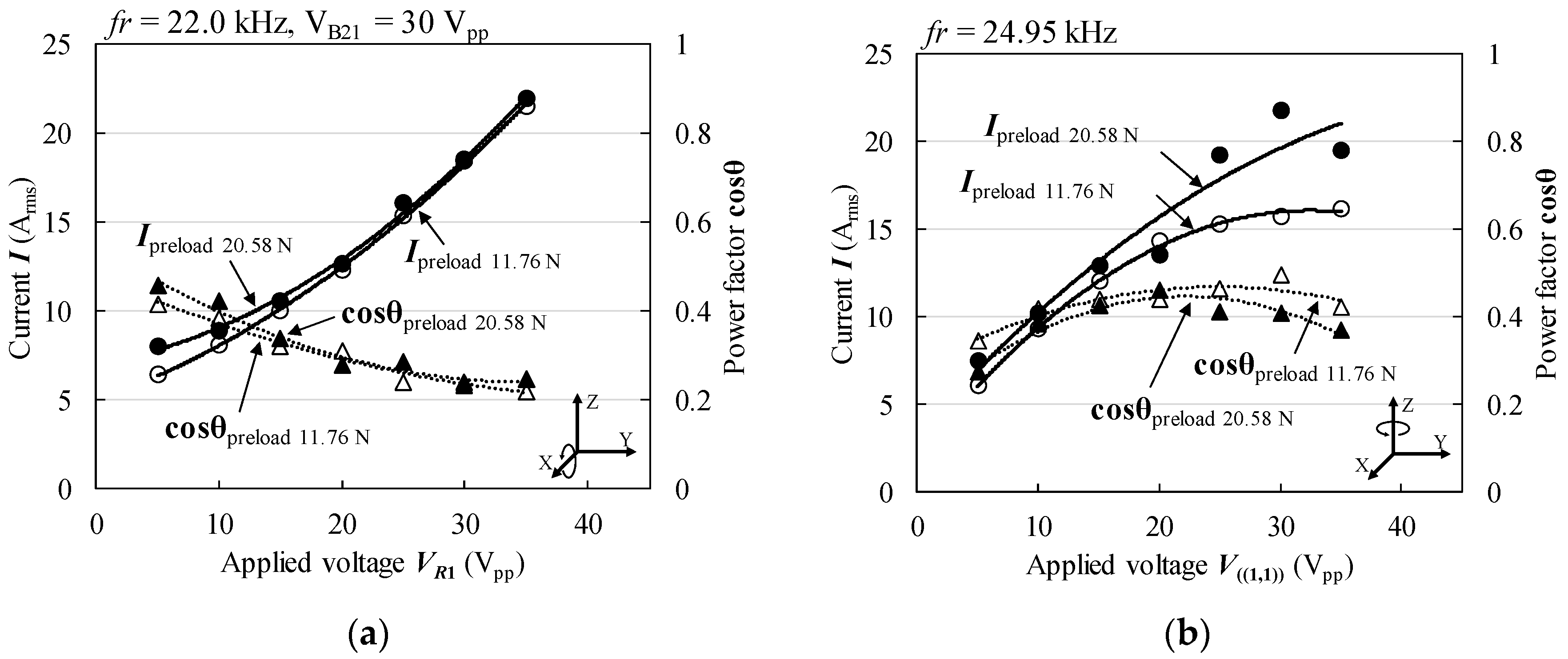
4.5. Current and Power Factor

Figure 17a,b show the measured effective values for current and power factor corresponding to the applied voltage shown in Figure 15, respectively. The prototype needed to be driven with large input power and high current, as shown in Figure 15 and Figure 17, because of the large capacitance of the MPAs, which made the power factor low (Figure 15). As a result, the maximum output current of the amplifiers (BP4610, NF Co., Yokohama, Japan) was reached before the full potential torque performance of the prototype motor was attained. Hence, the measured maximum torques were limited by the ability of the amplifiers to supply current. If the driving current supply were larger, a larger maximum torque and torque per unit weight could be obtained. Therefore, future studies will explore the improvement of the power factor for the driving circuit.

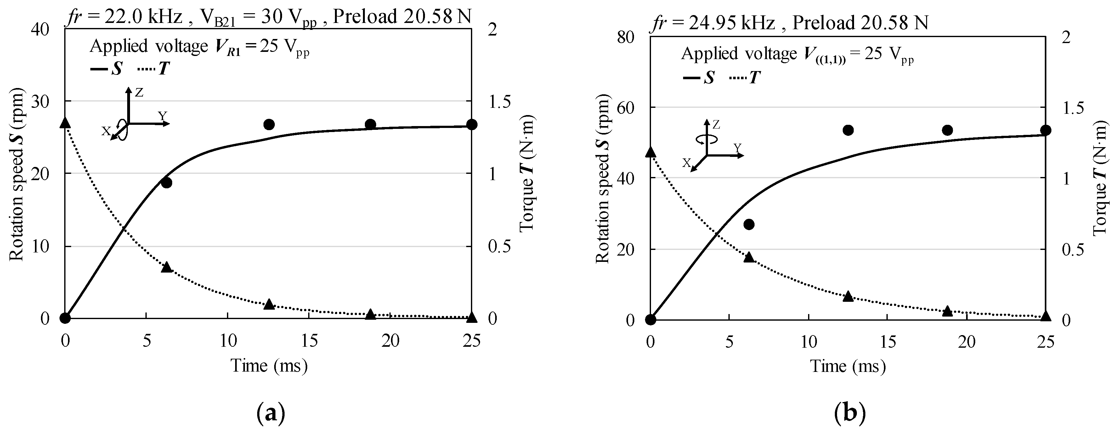
4.6. Transient Response and Load Characteristics

Figure 18a–d shows the transient response of the X-axis and Z-axis rotation speeds for preloads of 11.76 N and 20.58 N, as measured with a high-speed digital camera (1200 fps). The rise time was calculated using the rise curve of the rotation speed estimated by fitting each measured point. The estimated rise times were about 4 ms to 8 ms. The load characteristics were simulated by the moment of inertia of the rotor, the rise curve, and the calculated rise time [32]. Figure 19a–d shows the simulated load characteristics of X-axis and Z-axis rotations for preloads of 11.76 N and 20.58 N. The speed-load curves were derived from the gradient of the rise curve. The efficiency-load curves were estimated from the mechanical output and the electrical input power shown in Figure 15. The maximum torque almost agreed with the measured value shown in Figure 13. Maximum efficiencies of about 0.2% to 1.4% were obtained. The causes of the low efficiency were likely the high current flow and low power factor, as well as friction loss between the rotor and stator. Moreover, the MPAs, which were made of hard piezoelectric material provided with high mechanical quality factor, had large heat loss when driven at high frequency. Therefore, the first step for improving the efficiency will be to provide a power factor improvement circuit.

5. Conclusions

A high-torque sandwich-type MDOF-SUSM was designed for high-load applications. The design features a new annular stator that can strongly excite three different vibration modes using MPAs. The operating principle and sandwich structure of the prototype MDOF-SUSM are similar to those of a previously reported ϕ20 mm type. However, the new prototype not only is larger but also has a high-power excitation method and stable support mechanism. Moreover, the rigidity of the friction driving portion of the stator was enhanced to more effectively transmit the excited vibration force to the friction-driven surface. As a result, the prototype had very high torque compared with other MDOF-SUSMs, confirming the effectiveness of the excitation method and structural changes. The torque performance of the prototype MDOF-SUSM was limited by the output current of the amplifiers used during the performance examination. The load characteristics were calculated by measuring the transient response of the rotor rotation speed. The efficiency was low due to heat loss in the MPAs and a low power factor. If the electric power factor of stators can be improved to reduce the current required to drive the motor, the maximum torque, torque per unit weight, and efficiency will likely increase.

Supplementary Materials

The following are available online at https://www.mdpi.com/2076-0825/7/1/8/s1.

Acknowledgments

This work was partially supported by JSPS Kakenhi Grant Number 26289023.

Author Contributions

Koki Oikawa designed the structure, performed the fundamental experiments, and wrote a part of the paper; Ai Mizuno conceived to improve the performance and performed the experiments; Manabu Aoyagi directed the whole of this study; Hidekazu Kajiwara analyzed the performance; Hideki Tamura and Takehiro Takano contributed to the creation of the basic design concept and analyzed data; Ai Mizuno and Manabu Aoyagi wrote the final version of the paper.

Conflicts of Interest

The authors declare no conflict of interest. The founding sponsors had no role in the design of the study; in the collection, analyses, or interpretation of data; in the writing of the manuscript, and in the decision to publish the results.

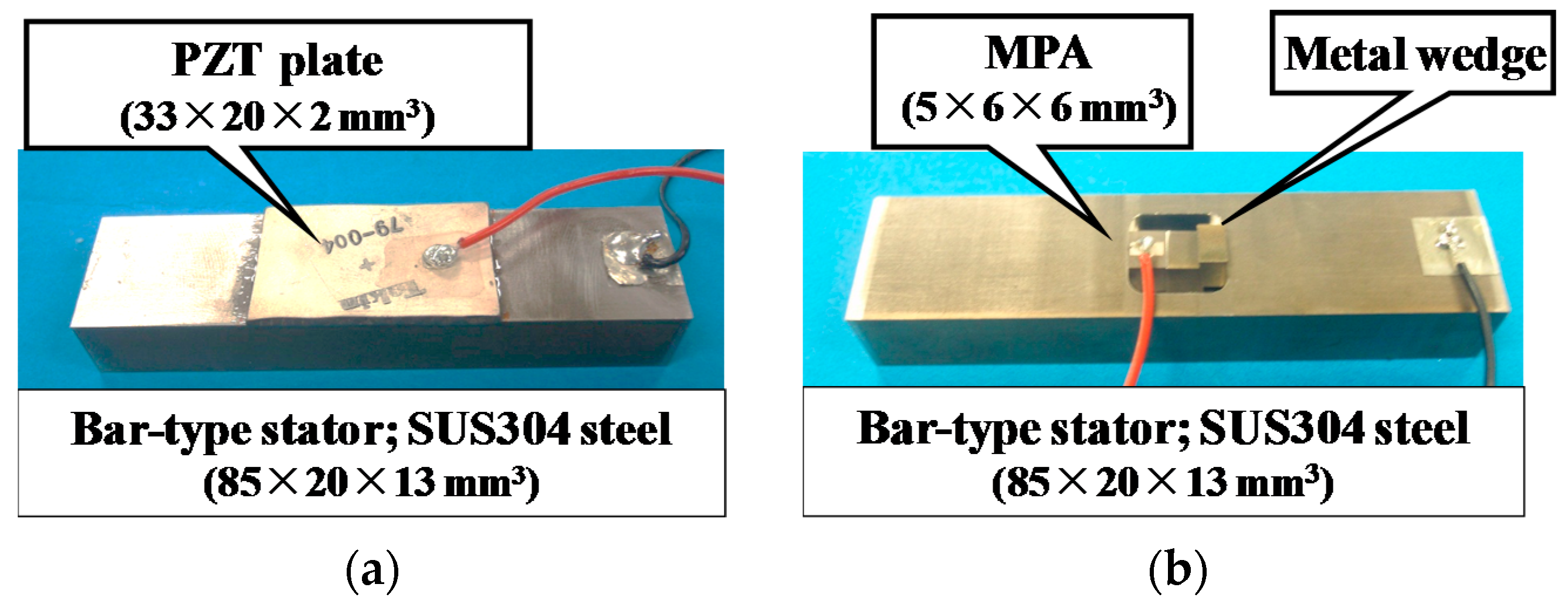
Appendix A. Comparison of Excitation Methods by MPAs and PZT Plate

A performance comparison was made for two excitation methods: (1) a PZT plate with polarization in the thickness direction bonded to the surface of a steel bar and (2) an MPA (6 × 6 × 5 mm3) made of hard piezoelectric ceramics embedded into a similar bar. Both piezoelectric devices were manufactured products. Their physical and piezoelectric properties are shown in Table A1. The PZT plate and MPA vibrators are shown in Figure A1a,b, respectively. The PZT plate was bonded at the center of the bar. The MPA was embedded into a rectangular hole formed on the bar, and it was secured in the hole with metal wedges, as shown in Figure 10c. The vibrator could independently excite the first bending mode (B1-mode) and the first longitudinal mode (L1-mode).
Figure A1. Photographs of rectangular bar vibrators. (a) Bonded PZT plate and (b) Embedded MPA.
Actuators 07 00008 g0a1
Table A1. Physical and piezoelectric properties of PZT and MPA.
Item UnitPZTMPA
Dielectric propertiesε33T/ε0 14001460
Curie temperature °C315310
Dielectric losstanδ%0.30.4
Piezoelectric strain constantd31×10−12 m/V−132−120
d33×10−12 m/V296315
Densityρ×103 kg/m37.767.6
Poison’s ratio 0.310.31
Young’s modulusY11×1010 Pa7.68.2
Mechanical quality factorQm 18002000
When an AC voltage of 5 Vpp was applied at the resonance frequency, measured force factors of both vibration modes of each vibrator were obtained (Table A2). The force factor is an indicator of the conversion efficiency from electrical energy to kinetic energy. The force factor was calculated by motional current divided by vibration velocity at the resonance frequency. The motional current was calculated by observing the input voltage and current to the piezoelectric element using an oscilloscope. The vibration velocity was measured on the surface of the bar using a laser Doppler vibrometer. The measurement point was set where the maximum vibration velocity was obtained, specifically the upper surface end of the bar in B1-mode and the side end of the bar in L1-mode. The force factor of B1-mode for the embedded MPA was about 3.7 times larger than that for the bonded PZT plate. In addition, the force factor of L1-mode for the embedded MPA was about 5.2 times larger than that of the bonded PZT plate. As a result, the excitation of the vibrator by an embedded MPA generated a larger force than could be obtained with the PZT plate. This is because the MPA utilizes the piezoelectric longitudinal effect, which has a larger force factor.
Table A2. Results of force factor measurement of PZT and MPA type vibrators.
ModeResonance Frequency (kHz)Vibration Velocity (mm/s rms)Motional Current (mA rms)Force Factor (N/V)
PZTMPAPZTMPAPZTMPAPZTMPA
B1-mode8.988.1021.22902.841440.1340.497
L1-mode29.727.76.854922.318630.3371.75

References

  1. Kaneko, K.; Yamada, I.; Itao, K. A Spherical DC Servo Motor with Three Degrees of Freedom. Trans. ASME Dyn. Syst. Meas. Control 1989, 111, 398–402. [Google Scholar] [CrossRef]
  2. Lee, K.M.; Kwan, C.K. Design Concept: Development of a Spherical Stepper for Robotic Applications. IEEE Trans. Robot. Autom. 1991, 7, 175–181. [Google Scholar] [CrossRef]
  3. Hollis, R.L.; Salcudean, S.E.; Allan, A.P. A Six-Degree-of-Freedom Magnetically Levitate Variable Compliance Fine-Motion Wrist: Design, Modeling, and Control. IEEE Trans. Robot. Autom. 1991, 7, 320–332. [Google Scholar] [CrossRef]
  4. Tsuda, M.; Higuchi, T.; Fujiwara, S. Magnetic Levitation Servo for Flexible Assembly Automation. J. Robot. Res. 1992, 11, 329–345. [Google Scholar] [CrossRef]
  5. Gosselin, C.M.; Hamel, J.F. The agile eye: A high-performance three degrees of freedom camera-orienting device. In Proceedings of the IEEE International Conference on Robotics and Automation (ICRA), San Diego, CA, USA, 8–13 May 1994; pp. 781–786. [Google Scholar]
  6. Chirikjian, G.S.; Stein, D. Kinematic Design and Commutation of a Spherical Stepper Motor. IEEE/ASME Trans. Mechatron. 1999, 4, 342–353. [Google Scholar] [CrossRef]
  7. Kahlen, K.; Doncker, R.W. Current regulators for multiple-phase permanent magnet spherical machines. In Proceedings of the IEEE Industrial Application, Rome, Italy, 8–12 October 2000; pp. 2011–2015. [Google Scholar]
  8. Wang, J.; Mitchell, K.; Jewell, G.W.; Howe, D. Multi-degree-of-freedom spherical permanent magnet motors. In Proceedings of the IEEE International Conference on Robotics and Automation (ICRA 2001), Seoul, Korea, 21–26 May 2001; pp. 1798–1805. [Google Scholar]
  9. Dehez, B.; Grenier, D.; Raucent, B. Two Degree of Freedom Spherical Actuator for Omnimobile ROBOT. In Proceedings of the IEEE International Conference on Robotics and Automation (ICRA), Washington, DC, USA, 11–15 May 2002; pp. 2381–2386. [Google Scholar]
  10. Yano, T.; Suzuki, T. Basic Characteristics of the Small Spherical Stepping Motor. In Proceedings of the IEEE IROS, Lausanne, Switzerland, 30 September–4 October 2002; pp. 1980–1985. [Google Scholar]
  11. Lee, K.M.; Joni, J. Concept Development and Design of a Spherical Wheel Motor (SWM). In Proceedings of the 2005 IEEE International Conference on Robotics and Automation (ICRA), Barcelona, Spain, 18–22 April 2005; pp. 3652–3657. [Google Scholar]
  12. Anders, M.; Binder, A.; Suess, M. A Spherical Linear Motor as Direct Drive of an Airborne Optical Infrared Telescope. In Proceedings of the IEEJ Transactions on Industry Applications, Kobe-Awaji, Japan, 25–28 September 2005; Volume 1, pp. 528–531. [Google Scholar]
  13. Kumagai, M.; Hollis, R.L. Development and Control of a Three DOF Spherical Induction Motor. In Proceedings of the IEEE International Conference on Robotics and Automation (ICRA), Karlsruhe, Germany, 6–10 May 2013; pp. 1520–1525. [Google Scholar]
  14. Toyama, S.; Sugitani, S.; Zhang, G.; Miyatani, Y.; Nakamura, K.N. Multi degree of freedom spherical ultrasonic motor. In Proceedings of the International Conference on Robotics and Automation, Nagoya, Japan, 21–27 May 1995; pp. 2935–2940. [Google Scholar]
  15. Hukaya, N.; Wada, H.; Kikuchi, Y.; Furuya, N.; Toyama, S. An artificial arm using an ultrasonic motor. Soc. Life Support Eng. 2000, 12, 131–136. (In Japanese) [Google Scholar]
  16. DOUBLE R and D Co., HP. Available online: http://www.j-d.co.jp/ (accessed on 15 April 2014).
  17. Morita, T.; Kurosuwa, M.; Higuchi, T. Design of a Cylindrical Ultrasonic Micromotor to Obtain Mechanical Output. Jpn. J. Appl. Phys. 1996, 35, 3251–3254. [Google Scholar] [CrossRef]
  18. Hata, H.; Tomikawa, Y.; Hirose, S.; Takano, T. Ring-Form Two-Dimensional (X–Y) Moving Piezoelectric Actuator. Jpn. J. Appl. Phys. 1996, 35, 5023–5026. [Google Scholar] [CrossRef]
  19. Amano, T.; Ishii, T.; Nakamura, K.; Ueha, S. An ultrasonic actuator with multi-degree of freedom using bending and longitudinal vibrations of a single stator. In Proceedings of the IEEE Ultrasonics Symposium, Sendai, Japan, 5–8 October 1998; pp. 667–670. [Google Scholar]
  20. Takemura, K.; Kojima, N.; Maeno, T. Development of a Bar-shaped Ultrasonic Motor for Multi-degrees of freedom Motion. In Proceedings of the 4th International Conference on Motion and Vibration Control, Zurich, Switzerland, 25–28 August 1998; pp. 195–200. [Google Scholar]
  21. Takemura, K.; Maeno, T. Design and control of an ultrasonic motor capable of generating multi-DOF motion. IEEE/ASME Trans. Mechatron. 2001, 6, 499–506. [Google Scholar] [CrossRef]
  22. Yun, C.-H.; Niwano, S.; Friend, J.R.; Nakamura, K.; Ueha, S. Support Mechanism for the Ball Rotor in the Three-Degree-of-Freedom Ultrasonic Motor. Jpn. J. Appl. Phys. 2003, 42, 3000–3001. [Google Scholar] [CrossRef]
  23. Takahashi, H.; Nishimura, O.; Akiba, T.; Tamura, H. Development of a 2DOF Control Type spherical Piezoelectric Motor with Wide Dynamic Range. In Proceedings of the Japan Society Precision Engineering Autumn Meet, Asahikawa, Japan, 12–14 September 2007; pp. 751–752. (In Japanese). [Google Scholar]
  24. Goda, Y.; Koyama, D.; Nakamura, K. Design of Multi-Degree-of-Freedom Ultrasonic Micromotors. Jpn. J. Appl. Phys. 2009, 48, 07GM06. [Google Scholar] [CrossRef]
  25. Khoo, T.F.; Dang, D.H.; Friend, J.; Oetomo, D.; Yeo, L. Triple degree-of-freedom piezoelectric ultrasonic micromotor via flexural-axial coupled vibration. IEEE Trans. Ultrason. Ferroelectr. Freq. Control 2009, 56, 1716–1724. [Google Scholar] [CrossRef] [PubMed]
  26. Mashimo, T.; Toyama, S.; Ishida, H. Design and Implementation of a Spherical Ultrasonic Motor. IEEE Trans. Ultrason. Ferroelectr. Freq. Control 2009, 56, 2514–2521. [Google Scholar] [CrossRef] [PubMed]
  27. Watson, B.; Friend, J.; Yeo, L.; Sitti, M. Piezoelectric ultrasonic resonant motor with stator diameter less than 250 μm: The Proteus motor. J. Micromech. Microeng. 2009, 19, 022001. [Google Scholar] [CrossRef]
  28. Aoyagi, M.; Nakajima, T.; Tomikawa, Y.; Takano, T. Examination of Disk-Type Multidegree-of-Freedom Ultrasonic Motor. Jpn. J. Appl. Phys. 2004, 43, 2884–2890. [Google Scholar] [CrossRef]
  29. Lu, B.; Aoyagi, M.; Takano, T.; Tamura, H. Examination of Sandwich-Type Multidegree-of-Freedom Spherical Ultrasonic Motor. Jpn. J. Appl. Phys. 2010, 49, 07HE24-1. [Google Scholar] [CrossRef]
  30. Lu, B.; Aoyagi, M.; Tamura, H.; Takano, T. Development of a Novel Rotor-Embedded-Type Multidegree-of-Freedom Spherical Ultrasonic Motor. J. Robot. Mechatron. 2012, 24, 876–883. [Google Scholar] [CrossRef]
  31. Lu, B.; Aoyagi, M. Examination of an Outer-Rotor-Type Multidegree-of-Freedom Spherical Ultrasonic Motor. In Proceedings of the 15th International Conference on Electrical Machines and Systems (ICEMS2012), Sapporo, Japan, 21–24 October 2012. [Google Scholar]
  32. Nakamura, K.; Kurosawa, M.K.; Kurebayashi, H.; Ueha, S. An estimation of load characteristics of an ultrasonic motor by measuring transient responses. IEEE Trans. Ultrason. Ferroelectr. Freq. Control 1991, 38, 482–485. [Google Scholar] [CrossRef] [PubMed]
Figure 1. Operating principle of the multiple degrees of freedom spherical ultrasonic motor MDOF-SUSM using annular vibrating stators.
Actuators 07 00008 g001
Figure 2. New stator construction using SUS304 steel. (a) Outside; (b) Inside; and (c) Cross-section A-A’.
Actuators 07 00008 g002
Figure 3. ϕ20 mm type stator construction using SUS304 steel. (a) Outside; (b) Inside; and (c) Cross-section A-A’.
Actuators 07 00008 g003
Figure 4. Strain distribution in the stator during each vibration mode. (a) R1-mode, (b) B21-mode, and (c) ((1,1))-mode. Animations of simulated vibration modes and an elliptical displacement motion are available as Supplement Materials.
Actuators 07 00008 g004
Figure 5. Dimensional parameters of the new stator.
Actuators 07 00008 g005
Figure 6. Simulated resonance frequency characteristics for the stator dimensional parameters identified in Figure 5. (a) R1; (b) R2; (c) R3; (d) R4; (e) T1; and (f) T2.
Actuators 07 00008 g006aActuators 07 00008 g006b
Figure 7. Component parts of sandwich structure used in the new stator.
Actuators 07 00008 g007
Figure 8. Analysis of support ring effects on stator. (a) Fixed portions of support ring and evaluation spots in the rotor contact portion of the stator; (b) Calculated standard deviation of the normalized simulated vibration amplitude of the stator at the evaluation spots during R1-mode excitation in finite element analysis (FEA).
Actuators 07 00008 g008
Figure 9. Arrangement of MPAs in the stator.
Actuators 07 00008 g009
Figure 10. Photographs of stator used in the prototype MDOF-SUSM. (a) Outside view and (b) Inside view. (c) Structure of embedded MPA secured to the stator using metal wedges.
Actuators 07 00008 g010
Figure 11. Dimensional drawings of stators designed for used in the MDOF-SUSM. (a) Prototype and (b) ϕ20 mm type.
Actuators 07 00008 g011
Figure 12. Admittance loops for each vibration mode in the prototype stator.
Actuators 07 00008 g012
Figure 13. Vibration displacement measured on the prototype stator surface during each vibration mode. (a) B21-mode; (b) R1-mode; and (c) ((1,1))-mode.
Actuators 07 00008 g013
Figure 14. Photograph of assembled prototype of the sandwich-type MDOF-SUSM.
Actuators 07 00008 g014
Figure 15. Maximum torque and electric input power with respect to applied voltage. (a) Rotation around X(Y)-axis and (b) Rotation around Z-axis.
Actuators 07 00008 g015
Figure 16. Comparison of maximum torque and torque per unit weight for various MDOF-SUSMs.
Actuators 07 00008 g016
Figure 17. Effective current and power factor with respect to applied voltage. (a) Rotation around X(Y)-axis and (b) Rotation around Z-axis.
Actuators 07 00008 g017
Figure 18. Transient response of rotation speed and torque with preload of 20.58 N. (a) Rotation around X(Y)-axis; and (b) Rotation around Z-axis.
Actuators 07 00008 g018
Figure 19. Load characteristics with preload of 20.58 N. (a) Rotation around X(Y)-axis, and (b) Rotation around Z-axis.
Actuators 07 00008 g019
Table 1. Excitation method of each vibration mode.
Phase Difference (deg)Vibration Mode
00R1-mode
180180B21-mode
1800((1,1))-mode
Notes: ① MPA pair on opposite sides (Port A–B or Port A–D) ② MPA pair on the inside and outside (1–2 in each port).
Table 2. Operation method of each rotation.
Vibration ModeRotation Direction
Ports A–BPorts C–D
R1-modeB21-modeAround X-axis
B21’-modeR1-modeAround Y-axis
((1,1))-mode((1,1))’-modeAround Z-axis
Table 3. Basic characteristics of stators with support ring attached.
Basic Characteristics of StatorR1-ModeB21-Mode((1,1))-Mode
Upper statorResonance frequency (kHz)22.1521.8824.98
Admittance (S)0.451.382.17
Lower statorResonance frequency (kHz)22.0921.8724.94
Admittance (S)0.441.251.86
Table 4. Comparison of torque performance between prototype and ϕ20 mm type.
Performance CharacteristicRotationPrototypeϕ20 mm Type [29]
Max torque (N∙m at Vpp)Around X(Y)-axis1.48 at 300.058 at 80
Around Z-axis2.05 at 400.084 at 140
Torque/weight (N∙m/kg)Around X(Y)-axis0.870.70
Around Z-axis1.201.02

