Design, Analysis and Testing of a New Compliant Compound Constant-Force Mechanism


Department of Electromechanical Engineering, Faculty of Science and Technology, University of Macau, Avenida da Universidade, Taipa, Macau, China
*
Author to whom correspondence should be addressed.
Actuators 2018, 7(4), 65; https://doi.org/10.3390/act7040065
Submission received: 31 August 2018
/
Revised: 21 September 2018
/
Accepted: 26 September 2018
/
Published: 27 September 2018
(This article belongs to the Special Issue Design and Control of Compliant Manipulators)
Abstract
:This paper presents the design and testing of a novel flexure-based compliant compound constant-force mechanism (CCFM). One uniqueness of the proposed mechanism lies in that it achieves both constant-force input and constant-force output, which is enabled by integrating two types of sub-mechanisms termed active and passive constant-force structures, respectively. Unlike conventional structures, the active constant-force structure allows the reduction on input force requirement and thus the enlargement of motion stroke provided that the maximum stress of the material is within allowable value. While the passive one offers a safe environmental interaction during the contact process. Analytical model of the proposed CCFM is derived which is verified by simulation study with finite element analysis (FEA). A prototype mechanism is fabricated by a 3D printer to demonstrate the performance of the proposed CCFM design. Experimental results reveal the effectiveness of the reported CCFM.
1. Introduction
Compliant mechanism exhibits the advantages of no backlash, no wear, and no friction [1,2,3,4]. It has been widely adopted in various applications including precision grippers [5], biological micromanipulators [6], and atomic force microscopes [7]. However, the flexure-based compliant mechanism usually needs precise position control and force feedback for practical applications. For instance, various control algorithms have been proposed in the literature [8,9]. To reduce the dependency on complex control algorithms and complicated parameter tuning processes, an alternative method based on constant-force mechanism (CFM) has been recently proposed from the viewpoint of mechanism design [10,11,12,13].
A traditional flexure mechanism follows Hooke’s law, i.e., the force is in proportional to the induced displacement [14]. Hooke’s law describes the constant stiffness of the material for simple and normed geometries. But, for complaint mechanism with large displacement or unfolding structures, the force-displacement properties can be non-linear. Thus, the Hooke’s law cannot be easily applied to the design of compliant CFM with zero stiffness. In particular, with the combination of negative-stiffness and positive-stiffness structures, the CFM obtains zero-stiffness character within a particular range of displacement. Moreover, the constant force can be obtained while the displacement varies in the constant-force motion range [15]. Such mechanism can be applied in the situations where the interaction force needs to be limited to a near constant value. As the force is governed by the mechanism design, the force sensor and controller are not needed [16]. Owing to this advantage, CFM has drawn the attention from several applications, such as exercise machine [17], micro-gripper [18], and bio-micromanipulation tools [15].
In the constant-force motion range, the compliant CFM exhibits zero value of total stiffness. To obtain this property, various approaches have been explored. A typical way to achieve constant-force property is obtained by using springs with vibrational damping theory. For example, two oblique coil springs are connected with a vertical coil spring to form a constant-force mechanism [19,20]. Another approach is proposed by using a mechanical spring and a magnetic spring [21,22]. In the aforementioned references, the low-stiffness isolators obtain near constant force property by using linear mechanical spring with positive stiffness and magnetic spring with negative stiffness. Alternatively, complaint mechanisms with flexure hinges have been widely adopted in CFM design. According to the cross-section shape, flexure hinges can be classified as elliptical flexure hinge [23], circular flexure hinge [24], right-angle flexure hinge [2], and so on. The flexure hinges have been analyzed in detail in the literature [25,26]. In particular, the complaint mechanism with buckled flexure hinges is commonly adopted to realize the negative stiffness in the constant-force mechanism. To name a few, the constant-force mechanism with bistable flexure hinges is proposed in the literature [27,28]. In addition, the constant force is obtained by the shape optimization of the lateral beams (which is cubic Bezier curve) and inner beams of a cosine curve in reference [29]. Another way is reported in reference [30], which is based on stiffness nonlinearity. It has been shown that a compliant Sarrus mechanism with cross-spring flexural pivots can obtain the constant-force property. An intuitive method to obtain the zero stiffness is to combine a positive-stiffness mechanism and a negative-stiffness mechanism together. A recent review of constant-force mechanism design has been reported in [31].
Generally, the constant-force mechanism can be divided into two categories, i.e., active constant-force mechanism (ACFM) and passive constant-force mechanism (PCFM). The ACFM indicates that the input force is a constant value [15]. Owing to the zero-stiffness property, the mechanism produces a larger travel range than that of conventional mechanism [32], given the same actuation force. On the contrary, the PCFM offers a constant-force output [18]. Such a mechanism can limit the contact force to the predesigned value within the constant-force displacement range. PCFM can also eliminate the dependency on force sensor and feedback controller while avoiding the overlarge force exerted on the environment. For practical applications, it is desirable to realize both constant-force input and constant-force output at the same time, so as to achieve both a larger motion stroke and a safer environmental interaction [33]. However, no such design has been reported in the literature.
The main contribution of this work is the design of a flexure-based complaint CCFM. The designed CCFM offers both constant-force input and constant-force output which is innovative in CFM design. In comparison with the previous work [34] which introduces an active constant-force mechanism with constant-force input (for generating a larger motion stroke than conventional mechanism), the proposed CCFM exhibits the feature of both active and passive types of constant-force structures. Thus, it enables both a larger stroke of motion and protection of operated object as compared with traditional mechanism. A preliminary study has been presented in the conference paper of the authors [35]. In the current work, more detailed study and experimental investigation have been carried out. The remaining parts of the paper are organized as follows. The mechanical design and modeling is presented in Section 2. In Section 3, simulation study is conduced with finite element analysis (FEA). Experimental studies are performed in Section 4. Finally, the conclusion is summarized in Section 5.
2. Mechanical Design
In this section, the mechanical design and analytical modeling of the new CCFM are presented in detail.
2.1. Schematic Design
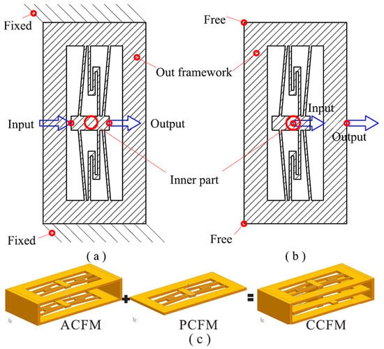
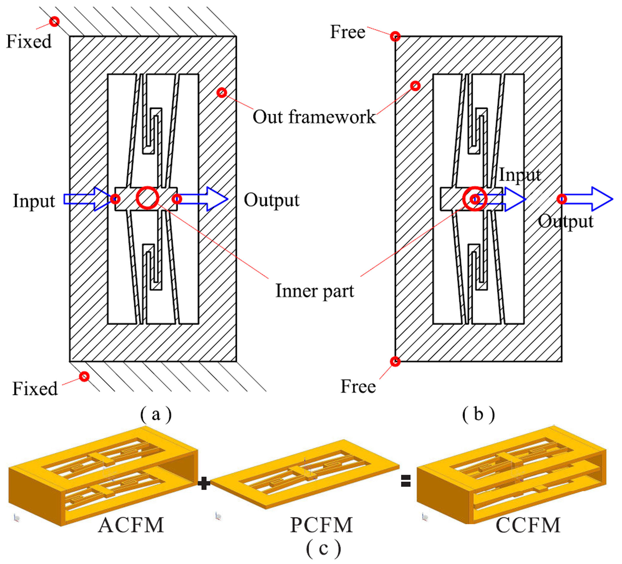
The designed CCFM is illustrated in Figure 1. It consists of three layers of the same structure. The basic layer contains four inclined, negative-stiffness leaf flexure hinges and two positive-stiffness folded leaf flexure hinges (see Figure 1a or b). The constant-force property is obtained by zeroing the stiffness of the flexure mechanism. The top and bottom layers act as ACFM, whose outer frames are fixed, as shown in Figure 1a. Both input and output ends refer to the inner part to yield the active constant-force property. The middle layer functions as PCFM, as shown in Figure 1b. Its input end refers to the inner part and the outer frame is set free to obtain the property of passive constant force. The CCFM is constructed by combining two ACFM (in top and bottom layers) and one PCFM (in middle layer), as shown in Figure 1c. Specifically, the ACFM and PCFM structures are connected by combining their inner parts together. In this way, the output force of the ACFM is transferred as the input force of the PCFM.
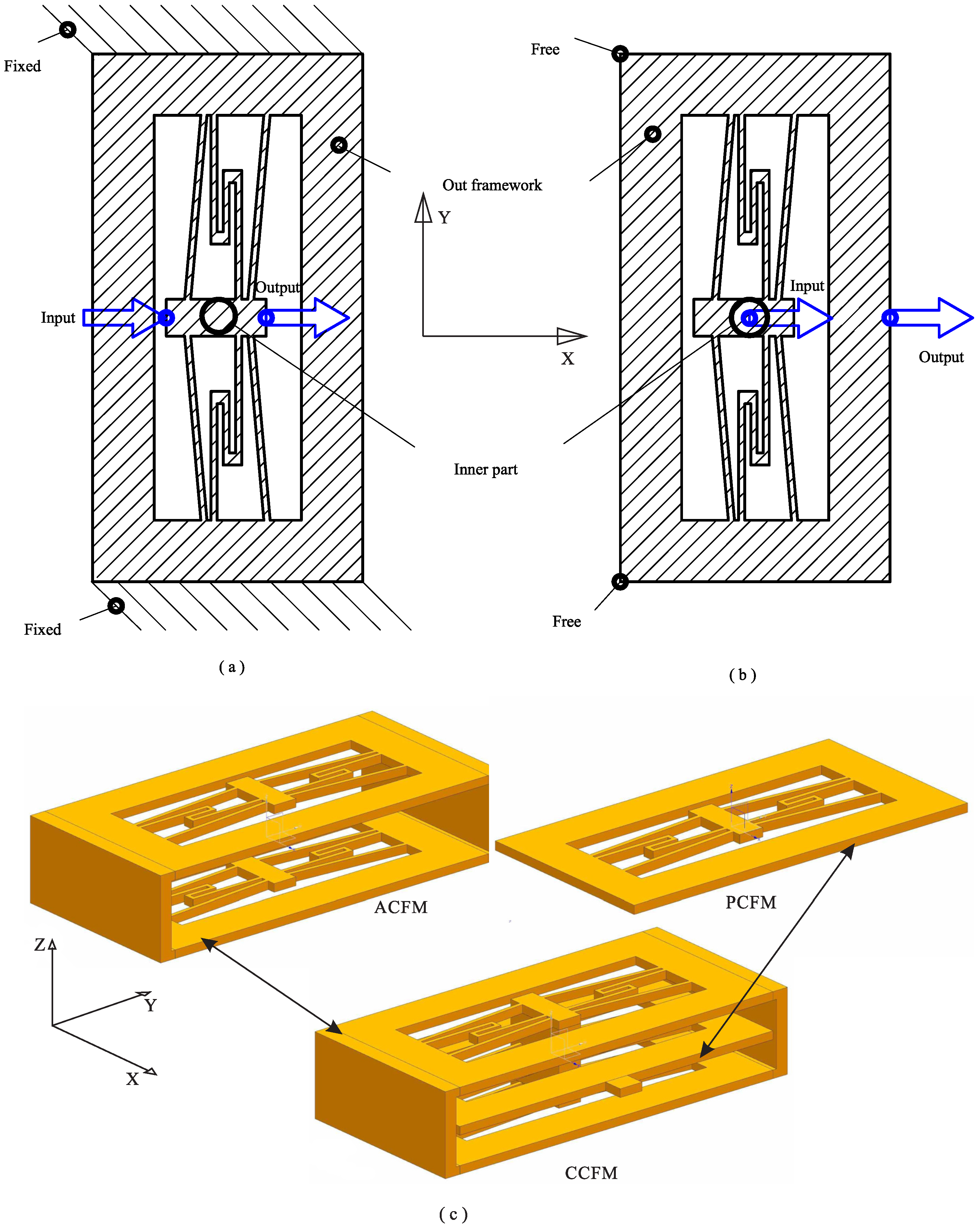
A possible prototype is illustrated in the computer-aided design (CAD) model in Figure 2. The CCFM is driven by a voice coil motor (VCM). The output end of the CCFM acts as an end-effector for interaction with the environment, which can be the fixed end or an object between the end-effector and fixed end. Owing to the nonlinear relationship between the force and displacement, when the CCFM is driven by the linear actuator, it obtains a larger stroke than a conventional mechanism. Whereas its output force is not a constant. To achieve a safe interaction with the environment, the end-effector offers a constant output force, which is enabled by the PCFM. Once the end-effector contacts the environment, the PCFM will be deformed to offer a constant interaction force in the constant-force displacement range. Thus, the contact force can be limited to a constant value.
With both ACFM and PCFM, the CCFM exhibits a large motion range and constant output force for a safe interaction. Due to the constant-force property, the proposed CCFM can be adopted in various applications (such as robot gripper) without using a force sensor and controller, which leads to cost reduction on hardware implementation.
2.2. Analytical Modeling
In the following, analytical modeling is conducted to evaluate the performance of the CCFM. As the CCFM is composed of three layers of the same structure, only one layer is analyzed. Due to its axial symmetry, one half-part is picked out for modeling. As shown in Figure 3, the left side is fixed, and the right side translates upward in vertical direction which is constrained by the symmetric design. In Figure 3, the dashed line represents the deformed CCFM with a displacement along x-axis.
In the working direction, the reaction force of one layer of CCFM can be derived as:
where and are the reaction forces produced by the positive-stiffness and negative-stiffness flexure hinges, respectively, as shown in Figure 3.
Based on mechanics analysis, the reaction force of each of the three flexure beams for the positive-stiffness folded leaf flexure hinge along x-axis can be derived as:
with where is the out-of-plane thickness of the layer and is the in-plane width of the flexure beams.
Thus, the total reaction force of the positive-stiffness folded leaf flexure hinge can be expressed by:
Based on the geometry relationship, (i = 1, 2, 3) can be derived as follows.
For the negative-stiffness flexure hinge, the motion of deflection is large and nonlinear. The pseudo-rigid-body model (PRBM) is not suitable for flexure beams with large deflection. Thus, the elliptic integral method is adopted in this work. The displacement is calculated by referring to [32]:
where is the first-kind incomplete elliptic integral and is the second-kind one. L is the length which can be expressed by . In addition, is the non-dimensional force with , where R represents the force experienced by the fixed face while is the angle between R and , as shown in Figure 3. Besides, corresponds to the amplitude of the elliptic integral. and can be derived as:
For the fixed-guided beam, the motion along y-axis is constrained as shown in Figure 3, Thus, a boundary condition is considered:
where
As the flexure hinge is orthogonal to the surface of the fixed support, one has
Hence, the unique solution has a relationship with for the first-order solution:
For second-order one:
Thus, the reaction force for the two components can be expressed as:
During the buckling of the inclined negative-stiffness leaf flexures, there will be one or two inflection points. More details can be referred to the literature [36].
Substituting Equations (3) and (15) into (1), the total reaction force along x-axis is calculated below.
Concerning the CCFM with three layers, the total force offered by the PCFM has an alternative relationship with . Assume that the clearance between the end-effector and environment is a. Before the end-effector contacts the environment, the CCFM is free of load, which means that the PCFM is not working. The total force of the ACFM can be derived as:
When the end-effector of the CCFM contacts the environment, it indicates that is larger than a. For the ACFM,
where represents an extra driving force.
For the PCFM,
2.3. Parametric Study
From the derived analytical models, it is observed that both material characteristic and mechanism parameters affect the constant-force property. In this work, the mechanism is fabricated by a 3D printer (model: uPrint SE Plus, from Stratasys Ltd., Eden Prairie, MN, USA). The corresponding material of ABSplus-P430 (Stratasys Ltd., Eden Prairie, MN, USA) [37] is selected due to its high elastic property. The specification data of the ABSplus material are shown in Table 1. Once the material is selected, the constant-force property is governed by the mechanism parameters. Thus, parametric study is conducted to examine the influence of each parameter on the mechanism performance.
The main geometric parameters of the mechanism are listed in Table 2. The smaller the in-plane width of the flexure, the larger the constant-force travel range. However, is limited by the fabrication accuracy in practice. For the 3D printer adopted in this work, the minimum in-plane width of the flexure beam is = 1.0 mm.
In addition, the smaller the out-of-plane thickness, the smaller the obtained constant force. To make a tradeoff between the constant force and loading capability, the out-of-plane thickness is selected as 2 mm as a case study. As the fabrication is realized by 3D printing, the inclined angle of the negative-stiffness flexure hinges is hard to be produced as a small value. Actually, if the angle is too large, the constant-force property cannot be achieved. If the angle is too small, the constant-force motion range will be shortened. Thus, is chosen as 5° by previous experience.
To get a better constant-force property, is the main parameter to determine the positive stiffness. Hence, the parametric investigation on for the folded beam-based flexure hinge is conducted and the result is shown in Figure 4. It can be observed that the mechanism yields the best constant-force property when = 19 mm, as it generates the smallest fluctuation of the force in range from 1.5 to 3 mm.
3. Simulation Study with FEA
In this section, an FEA simulation study is conducted with ANSYS Workbench software to verify the derived analytical models and to evaluate the performance of the presented CCFM. In addition, stress analysis and modal analysis are carried out to further examine its performance. In FEA simulation, the material’s data are shown in Table 1, and other settings remain as default in the software. In addition, the weight effect is not considered as it is a planar mechanism and the density of the plastic material is relatively low.
3.1. Static Structural Results of Constant-Force Test
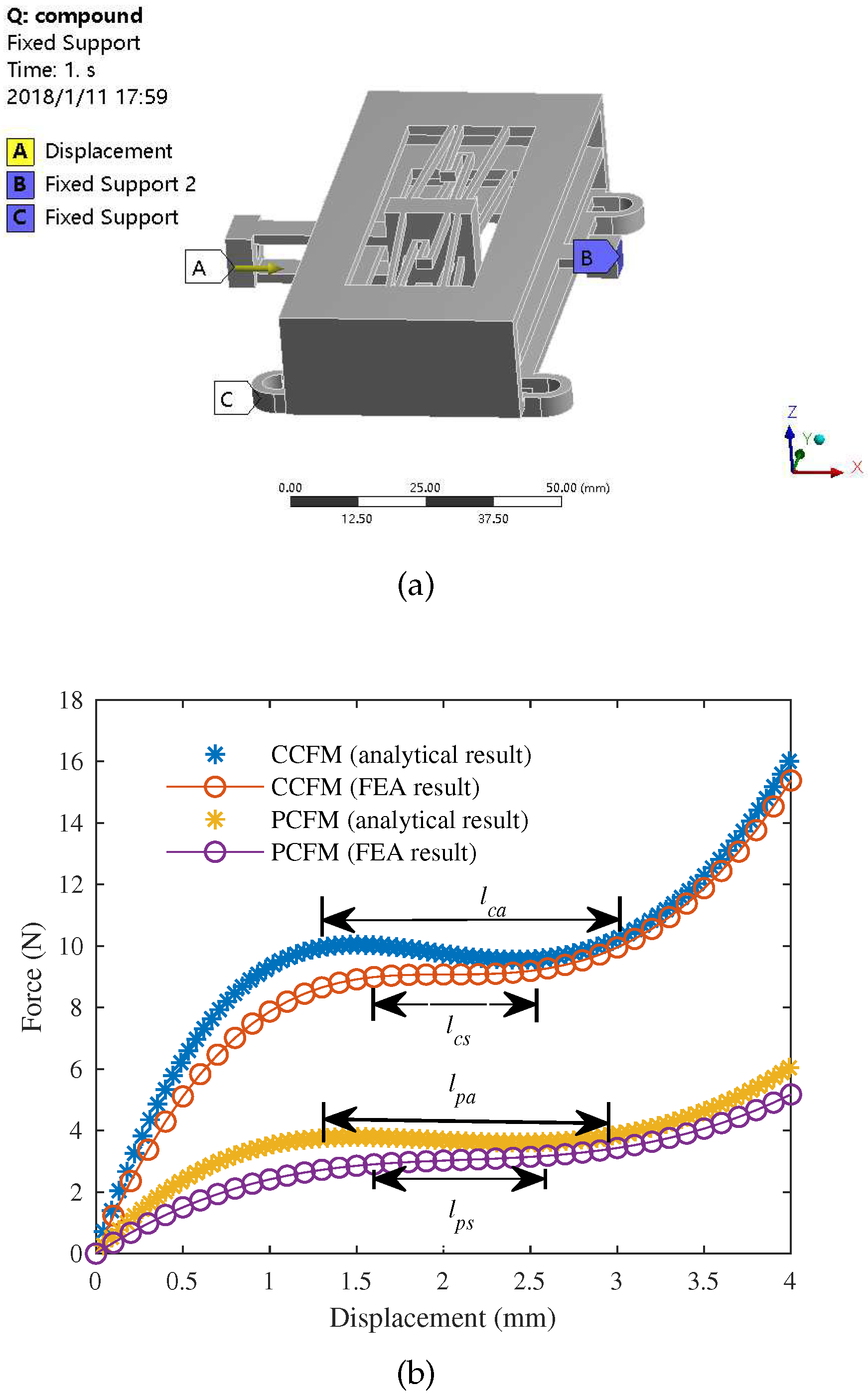
To test the constant-force property of the CFM, the FEA simulation is conducted by assuming that the end-effector contacts a rigid environment initially. Thus, both PCFM and ACFM will work at the same time. Analytical model predicts that the displacement ranges from 0 to 4.0 mm. Such a displacement is applied at the surface A as shown in Figure 5a. In ANSYS Workbench operation panel for FEA simulation, the displacement (d) is defined as a function of the time, i.e., . In analysis setting, the time is corresponding to simulation step. Thus, with 41 steps, an increasing displacement with the desired upper bound value of 4.0 mm is obtained. In addition, the option of large deformation is turned on in ANSYS software to account for the buckling behavior in nonlinear modeling. To evaluate the performance of the PCFM, the surface B (see Figure 5a) is fixed. The CCFM is fixed on the base by four bolts. Based on such setup, the relationships between the displacement and force for both PCFM and CCFM can be investigated with ANSYS software. Besides, the data of ACFM can be obtained by numerical calculation from those of PCFM and CCFM.
To illustrate the results clearly, the active and passive constant-force ranges are defined as illustrated in Figure 5b. Parameters and represent the analytical model and FEA simulation results for the active constant-force range, respectively. In addition, and denote the analytical model and FEA simulation results for the passive constant-force range, respectively. The constant-force range is defined as the displacement range where the constant force have a deviation within ±5% of the force magnitude.
The result of CCFM is shown by the curve with circle symbol in Figure 5b. In the initial travel displacement from 0 to 1.5 mm, the total stiffness of the PCFM is positive. In the next travel around the displacement from 1.5 to 2.5 mm, the stiffness is nearly zero. Simulation results show that the mechanism can obtain the constant-force range = 1.0 mm with an input force of 9.0 N. Comparing the simulation result with analytical model result of for CCFM, the constant-force travel range is about 0.75 mm smaller. The discrepancy between the analytical model and simulation results is caused by the simplification adopted in the analytical modeling process.
For the PCFM, the result is illustrated by the curve with triangular symbol. It exhibits a constant force of 3.0 N. The constant-force (with 5% variation) travel displacement ranges from 1.5 mm (2.85 N) to 2.6 mm (3.14 N). Thus, without using a force control, the maximum contact force that is imposed on the environment is limited. As compared with the analytical model result, the simulation result of zero-stiffness travel for the ACFM is about 0.5 mm lower. It is notable the magnitude of the constant-force can be adjusted by selecting different parameters for the flexure beams.
3.2. Stress Analysis Results
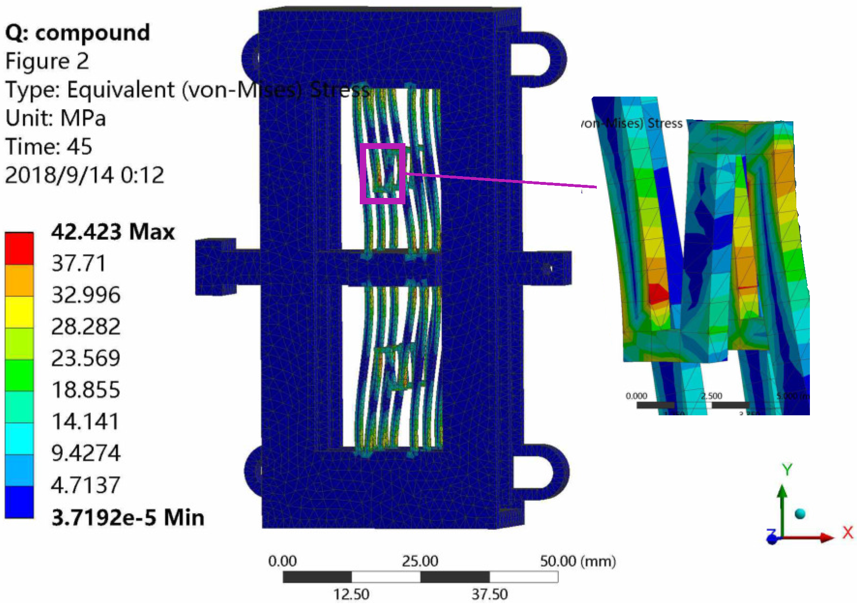
To examine whether the adopted material of ABSplus can work properly for the fabricated prototype, the equivalent stress analysis on CCFM is conducted by FEA simulation study. Specifically, the von-Mises equivalent stress is used, because it can be used to evaluate isotropic and ductile materials when subjected to a complex loading condition. The simulation result is shown in Figure 6. The maximum stress occurs in the middle of folded positive-stiffness flexure beams as additional zoomed sectional view. It is observed that the maximum stress of 42.4 MPa is sustained by the leaf flexure hinge. It is lower than the yield strength 68.9 MPa of the adopted material, which is used to fabricate the mechanism prototype. In addition, a safety factor of 68.9/42.4 = 1.6 is obtained for the material.
3.3. Modal Analysis Results
To evaluate the dynamic performance of the mechanism, modal analysis is conducted with ANSYS software. The most interesting result is the first resonant mode occurring in the working direction. The results are given in Table 3, which indicates that the first resonant mode is attributed to the swing motion of the input and output ends. The resonant frequency is 46.7 Hz, which is acceptable during the low-speed interaction. The second and third modes occur at 85.0 Hz and 85.7 Hz, respectively. The fourth mode exhibits a frequency of 115.4 Hz, which occurs in the working direction. In addition, the sixth mode indicates a rotational motion along z-axis with a frequency of 201.3 Hz.
4. Experimental Results
4.1. Experimental Setup
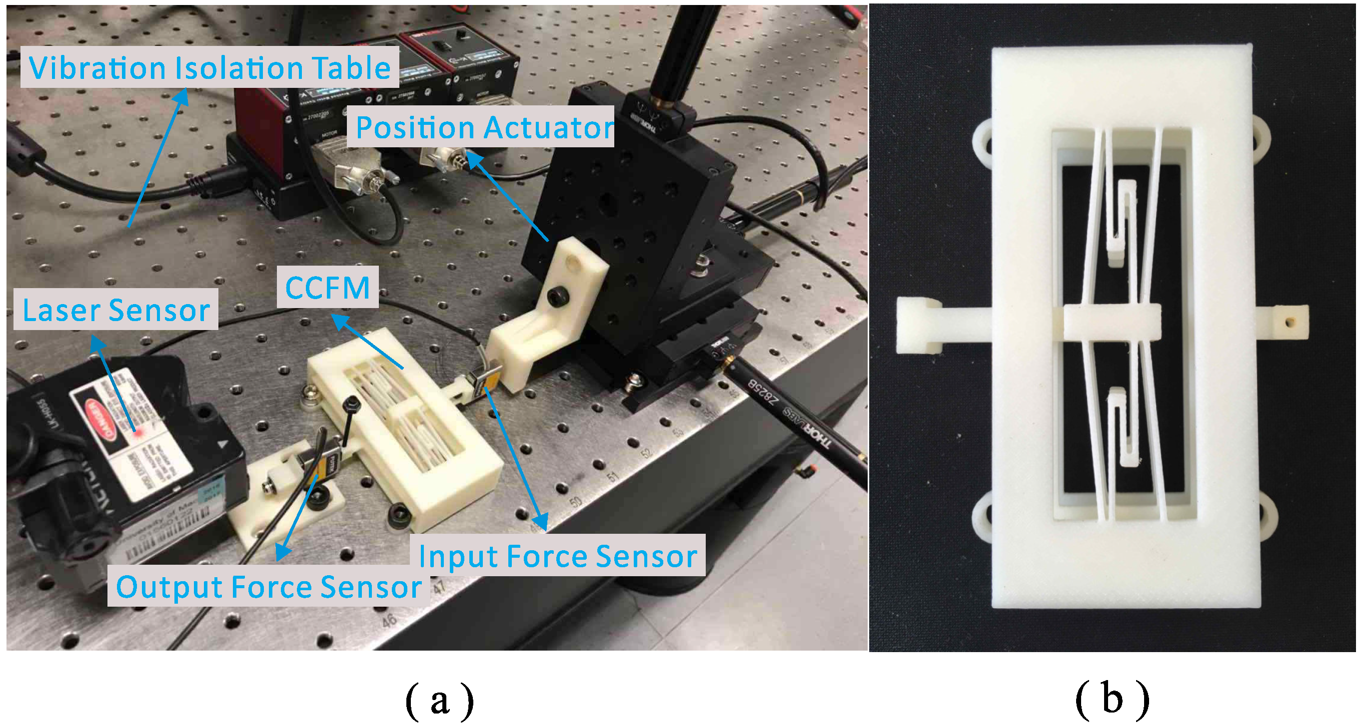
A CCFM prototype is fabricated by a 3D printer (model: uPrint SE Plus, from Stratasys Ltd., Eden Prairie, MN, USA) due to its advantage of time efficiency. The adopted material of ABSplus is durable enough in normal operations, as revealed in previous Section 3.2. The experimental setup is shown in Figure 7. To test the constant-force ranges of ACFM and PCFM, the CCFM is driven a motorized stage (model: Z285, from Thorlabs Inc., Newton, NJ, USA). Two force sensors (model: LSB200, from FUTEK Advanced Sensor Technology, Inc., Irvine, CA, USA) are mounted at the input and output ends to measure the force of ACFM and PCFM, respectively. A laser displacement sensor (model: LK-H055, from Keyence Corp., Osaka, Japan) is used to measure the displacement of the end-effector. In addition, a real-time controller (model: PXIe-1082, from National Instruments Corp., Austin, TX, USA) is employed to collect the sensor data. LabVIEW software is adopted to realize a real-time data acquisition system for device.
4.2. Experimental Results
In the experiment, the gripper prototype is driven by the motorized stage to examine its constant-force motion range using the experimental setup as shown in Figure 7a. Two force sensors are mounted at input and output terminals to measure the forces of CCFM and PCFM, respectively. In addition, the displacement of the output end is measured by the laser displacement sensor. The experiment has been repeated five times. The mean values of the experimental results are shown in Figure 8.
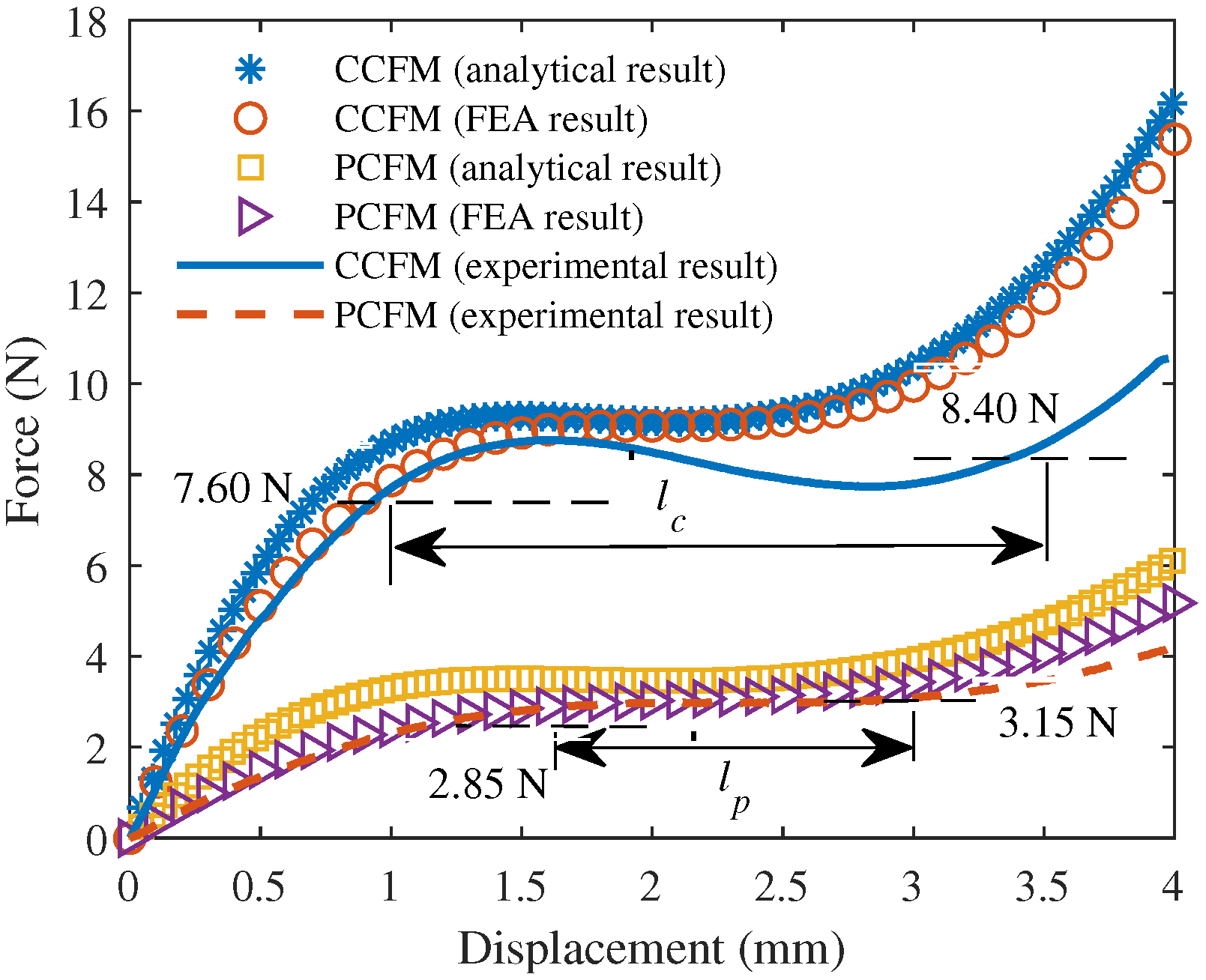
It is observed that the compound constant-force is 8.00 N, and the passive constant-force is 3.00 N. To characterize the constant-force motion range, the interval of force variation is used. Regarding the PCFM, the constant-force value has a variation of 3 ± 0.15 N. When the displacement reaches 1.7 mm, the constant-force value is 2.85 N. When the constant-force value reaches 3.15, the displacement is up to 3.0 mm. Thus, the constant-force motion range () for the PCFM is 1.3 mm (ranging from 1.7 to 3.0 mm). Similarly, the compound constant-force motion range is derived based on the variation of 8 ± 0.4 N. It is observed that the constant-force motion range () for the compound constant-force mechanism is 2.5 mm, ranging from 1.0 to 3.5 mm.
Repeated by five times, consistent experimental results are obtained. Concerning the CCFM, the standard deviation () of the compound constant-force magnitude is only 0.01 N. Based on t-distribution, the 95% confidence interval for the mean of constant-force magnitude is calculated as: 8.00 ± 0.01 N. For a clear comparison, the results of analytical model, FEA simulation, and experimental study are tabulated in Table 4. In comparison with experimental result, the analytical model and simulation results are 12.5% and 11.3% larger, respectively. The deviations are mainly induced by the fabrication errors of the prototype.
4.3. Further Discussions
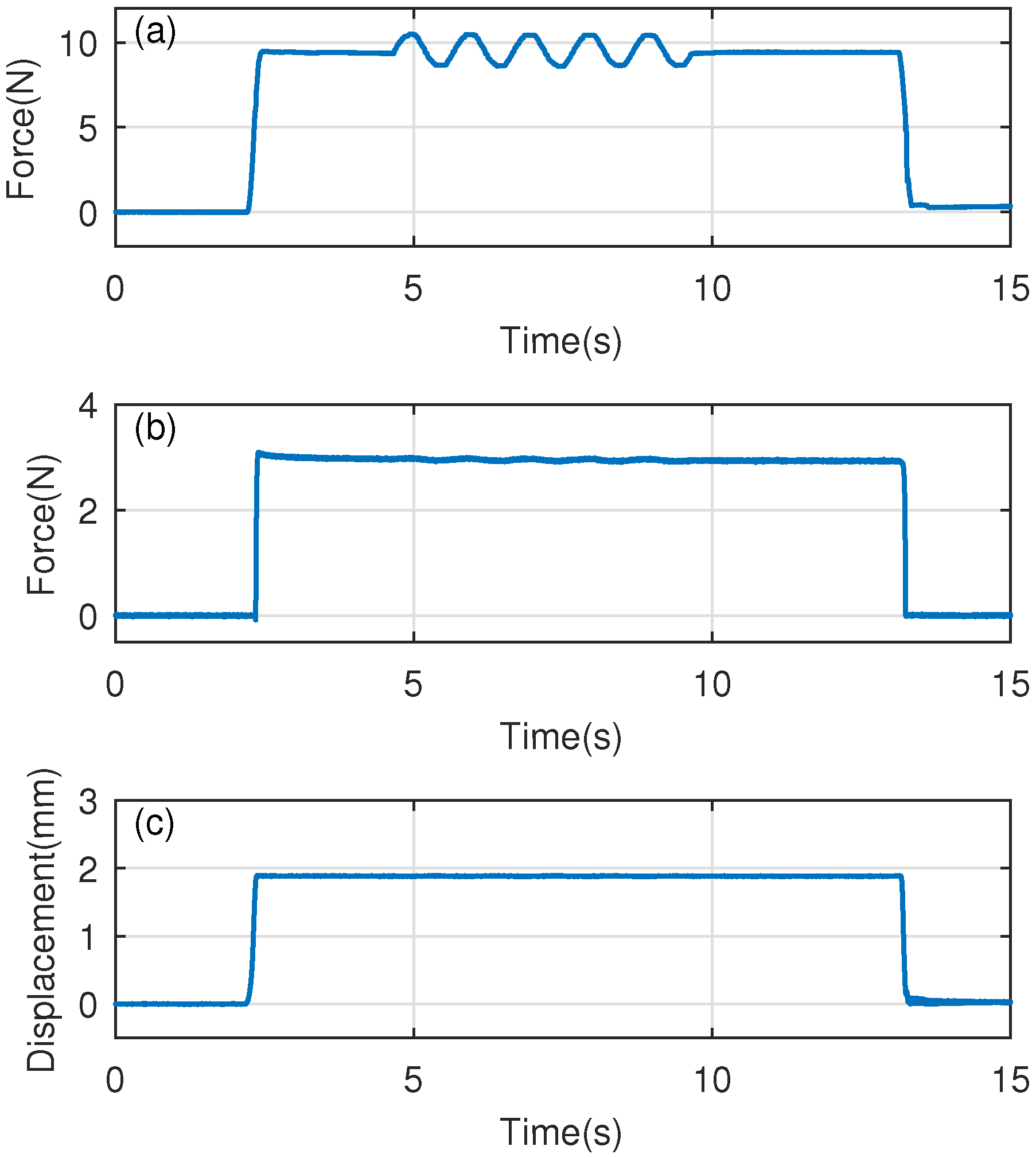
It is notable that there is a passive constant-force motion range of 1.3 mm as shown in Figure 8. This displacement interval is helpful to tolerate external disturbance while interacting with the environment, because the unwanted displacement output induced by potential disturbances will be absorbed by the PCFM within the constant-force motion range. To illustrate such capability, a step input force signal is firstly applied on the input end of the CCFM, and a disturbance force with peak-to-peak value of 2 N (see Figure 9a) is then manually added during the environmental interaction process. The time histories of the force and displacement signals are shown in Figure 9b,c. It is observed from Figure 9b that no oscillation appears on the output force. Moreover, only a small force variation (0.05 N) is induced on the output force of the end-effector, which is enabled by the PCFM mechanism. The experimental results demonstrate the fine capability of disturbance force suppression for the developed CCFM mechanism.
Generally, the actual stroke of a flexure mechanism is limited by the maximum stress of the material. Here, we assume that the maximum stress is within the allowable value. Then, given an actuator with specific driving force, the stroke is governed by the stiffness of the mechanism. Due to a lower stiffness of the active constant-force structure, the same stroke is obtained with a lower driving force than the conventional structure. It is notable that the planar size of the fabricated CCFM is 94 mm × 72 mm, which can be optimized to obtain a more compact dimension. Moreover, the overall size and constant-force displacement range of the CCFM can be adjusted to cater to specific applications.
5. Conclusions
This paper presents the design and testing of a novel flexure-based compound constant-force mechanism. The flexure mechanism with leaf flexure hinges can offer a good constant-force property. With the combination of active and passive constant-force structures, the proposed CCFM exhibits a large stroke with reduced requirement on actuator driving force and provides a displacement range with constant-force output during the environmental interaction phase without using an extra control algorithm. Simulation results confirm the performance of the proposed CCFM. A prototype is fabricated to verify the presented mechanism design and to demonstrate its performance by experimental studies. Results validate the effectiveness of the proposed design as well as analytical model and FEA simulation results.
The leaf flexures with distributed compliance have been adopted to design the constant-force mechanism. It is notable that flexure hinges with concentrated compliance can also be employed to construct the constant-force mechanism. Moreover, the use of optimized flexure hinges is a potential approach to design the constant-force mechanism. In the future work, the mechanism will be miniaturized into smaller scale for micro-/nano-manipulation task. Referring to the influence of scaling and the similitude of mechanisms and compliant mechanisms [38,39], a new parametric study needs to be conducted to generate a good constant-force magnitude and motion range.
Author Contributions
X.Z. performed the literature view and mechanism design; X.Z. and G.W. conducted the experimental study; X.Z., G.W. and Q.X. wrote the paper.
Funding
This work was supported by the National Natural Science Foundation of China under Grant No. 51575545, the Macao Science and Technology Development Fund under Grant No. 179/2017/A3, and the Research Committee of University of Macau under Grant No. MYRG2018-00034-FST.
Conflicts of Interest
The authors declare no conflict of interest. The founding sponsors had no role in the design of the study; in the collection, analyses, or interpretation of data; in the writing of the manuscript, and in the decision to publish the results.
References
- Howell, L.L. Compliant Mechanisms; John Wiley & Sons: New York, NY, USA, 2001. [Google Scholar]
- Lobontiu, N. Compliant Mechanisms: Design of Flexure Hinges; CRC Press: Boca Raton, FL, USA, 2002. [Google Scholar]
- Xu, Q. Design and Implementation of Large-Range Compliant Micropositioning Systems; John Wiley & Sons: Singapore, 2016. [Google Scholar]
- Luo, Y.; Liu, W. Analysis of the displacement of distributed compliant parallel-guiding mechanism considering parasitic rotation and deflection on the guiding plate. Mech. Mach. Theory 2014, 80, 151–165. [Google Scholar]
- Chen, W.; Qu, J.; Chen, W.; Zhang, J. A compliant dual-axis gripper with integrated position and force sensing. Mechatronics 2017, 47, 105–115. [Google Scholar] [CrossRef]
- Xu, Q. Micromachines for Biological Micromanipulation; Springer: Cham, Switzerland, 2018. [Google Scholar]
- Park, J.H.; Shim, J.; Lee, D.Y. A compact vertical scanner for atomic force microscopes. Sensors 2010, 10, 10673–10682. [Google Scholar] [CrossRef] [PubMed]
- Xu, Q. Robust impedance control of a compliant microgripper for high-speed position/force regulation. IEEE Trans. Ind. Electron. 2015, 62, 1201–1209. [Google Scholar] [CrossRef]
- Choi, S.; Han, Y.; Kim, J.; Cheong, C. Force tracking control of a flexible gripper featuring shape memory alloy actuators. Mechatronics 2001, 11, 677–690. [Google Scholar] [CrossRef]
- Herder, J.L.; Van Den Berg, F.P.A. Statically balanced compliant mechanisms (SBCMs), an example and prospects. In Proceedings of the Design Engineering Technical Conferences and Computer in Engineering Conference DETC2000/MECH-14144, Baltimore, MD, USA, 10–13 September 2000. [Google Scholar]
- Tolman, K.A.; Merriam, E.G.; Howell, L.L. Compliant constant-force linear-motion mechanism. Mech. Mach. Theory 2016, 106, 68–79. [Google Scholar] [CrossRef]
- Li, B.; Hao, G. Nonlinear behaviour design using the kinematic singularity of a general type of double-slider four-bar linkage. Mech. Mach. Theory 2018, 129, 106–130. [Google Scholar] [CrossRef]
- Zanaty, M.; Vardi, I.; Henein, S. Programmable multistable mechanisms: Synthesis and modeling. J. Mech. Des. 2018, 140, 042301. [Google Scholar] [CrossRef]
- Dong, W.; Chen, F.; Gao, F.; Yang, M.; Sun, L.; Du, Z.; Tang, J.; Zhang, D. Development and analysis of a bridge-lever-type displacement amplifier based on hybrid flexure hinges. Precis. Eng. 2018. [Google Scholar] [CrossRef]
- Wang, P.; Xu, Q. Design and testing of a flexure-based constant-force stage for biological cell micromanipulation. IEEE Trans. Autom. Sci. Eng. 2018, 15, 1114–1126. [Google Scholar] [CrossRef]
- Lan, C.; Wang, J.; Chen, Y. A compliant constant-force mechanism for adaptive robot end-effector operations. In Proceedings of the 2010 IEEE International Conference on Robotics and Automation (ICRA), Anchorage, AK, USA, 3–8 May 2010; pp. 2131–2136. [Google Scholar]
- Howell, L.; Magleby, S. Substantially Constant-Force Exercise Machine. U.S. Patent 20040198571A1, 7 October 2004. [Google Scholar]
- Liu, Y.; Zhang, Y.; Xu, Q. Design and Control of a Novel Compliant Constant-Force Gripper Based on Buckled Fixed-Guided Beams. IEEE/ASME Trans. Mech. 2017, 22, 476–486. [Google Scholar] [CrossRef]
- Carrella, A.; Brennan, M.; Kovacic, I.; Waters, T. On the force transmissibility of a vibration isolator with quasi-zero-stiffness. J. Sound Vib. 2009, 322, 707–717. [Google Scholar] [CrossRef]
- Kovacic, I.; Brennan, M.J.; Waters, T.P. A study of a nonlinear vibration isolator with a quasi-zero stiffness characteristic. J. Sound Vib. 2008, 315, 700–711. [Google Scholar] [CrossRef]
- Carrella, A.; Brennan, M.; Waters, T.; Shin, K. On the design of a high-static–low-dynamic stiffness isolator using linear mechanical springs and magnets. J. Sound Vib. 2008, 315, 712–720. [Google Scholar] [CrossRef]
- Zhou, N.; Liu, K. A tunable high-static–low-dynamic stiffness vibration isolator. J. Sound Vib. 2010, 329, 1254–1273. [Google Scholar] [CrossRef]
- Smith, S.T.; Badami, V.G.; Dale, J.S.; Xu, Y. Elliptical flexure hinges. Rev Sci Instrum. 1997, 68, 1474–1483. [Google Scholar] [CrossRef]
- Tseytlin, Y.M. Notch flexure hinges: an effective theory. Rev Sci Instrum. 2002, 73, 3363–3368. [Google Scholar] [CrossRef]
- Verotti, M. Effect of initial curvature in uniform flexures on position accuracy. Mech. Mach. Theory 2018, 119, 106–118. [Google Scholar] [CrossRef]
- Verotti, M. Analysis of the center of rotation in primitive flexures: Uniform cantilever beams with constant curvature. Mech. Mach. Theory 2016, 97, 29–50. [Google Scholar] [CrossRef]
- Pham, H.T.; Wang, D.A. A constant-force bistable mechanism for force regulation and overload protection. Mech. Mach. Theory 2011, 46, 899–909. [Google Scholar] [CrossRef]
- Wang, P.; Xu, Q. Design of a flexure-based constant-force XY precision positioning stage. Mech. Mach. Theory 2017, 108, 1–13. [Google Scholar] [CrossRef]
- Wang, D.A.; Chen, J.H.; Pham, H.T. A constant-force bistable micromechanism. Sens. Actuators A Phys. 2013, 189, 481–487. [Google Scholar] [CrossRef]
- Chen, G.; Chang, H.; Li, G. Design of Constant-Force Compliant Sarrus Mechanism Considering Stiffness Nonlinearity of Compliant Joints. In Advances in Reconfigurable Mechanisms and Robots II; Springer: Basel, Switzerland, 2016; pp. 107–116. [Google Scholar]
- Wang, P.; Xu, Q. Design and modeling of constant-force mechanisms: A survey. Mech. Mach. Theory 2018, 119, 1–21. [Google Scholar] [CrossRef]
- Xu, Q. Design of a Large-Stroke Bistable Mechanism for the Application in Constant-Force Micropositioning Stage. J. Mech. Robot. 2017, 9, 011006. [Google Scholar] [CrossRef]
- Wang, J.; Lan, C. A constant-force compliant gripper for handling objects of various sizes. J. Mech. Des. 2014, 136, 071008. [Google Scholar] [CrossRef]
- Zhang, X.; Xu, Q. Design and analysis of a constant-force parallel micro-gripper. In Proceedings of the 2017 IEEE International Conference on Robotics and Biomimetics (ROBIO), Macau, China, 5–8 December 2017; pp. 1112–1117. [Google Scholar]
- Zhang, X.; Xu, Q. Design and Analysis of a Compound Constant-Force Mechanism for Compliant Gripper. In Proceedings of the 3rd International Conference on Manipulation, Automation and Robotics at Small Scales (MARSS), Nagoya, Japan, 4–8 July 2018. [Google Scholar]
- Zhao, J.; Jia, J.; He, X.; Wang, H. Post-buckling and snap-through behavior of inclined slender beams. J. Appl. Mech. 2008, 75, 041020. [Google Scholar] [CrossRef]
- ABSplus. Available online: http://www.stratasys.com/materials/search/absplus (accessed on 19 September 2018).
- Linß, S.; Gräser, P.; Räder, T.; Henning, S.; Theska, R.; Zentner, L. Influence of geometric scaling on the elasto-kinematic properties of flexure hinges and compliant mechanisms. Mech. Mach. Theory 2018, 125, 220–239. [Google Scholar] [CrossRef]
- Hanke, U.; Lovasz, E.C.; Zichner, M.; Modler, N.; Comsa, A.; Modler, K.H. Synthesis of PR/RP-chain based compliant mechanisms: Design of applications exploiting fibre reinforced material characteristics. Mach. Sci. 2015, 6, 155–161. [Google Scholar] [CrossRef]
Figure 1.
Schematic of the proposed CCFM. (a) ACFM in top and bottom layers; (b) PCFM in middle layer; (c) Construction of the CCFM.
Figure 1.
Schematic of the proposed CCFM. (a) ACFM in top and bottom layers; (b) PCFM in middle layer; (c) Construction of the CCFM.

Figure 2.
Example of CAD model for the CCFM. (1) Base board, (2) connector 1, (3) connector 2, (4) connector 3, (5) permanent magnetic housing, (6) moving coil, (7) CCFM, (8) end-effector, and (9) fixed end.
Figure 2.
Example of CAD model for the CCFM. (1) Base board, (2) connector 1, (3) connector 2, (4) connector 3, (5) permanent magnetic housing, (6) moving coil, (7) CCFM, (8) end-effector, and (9) fixed end.

Figure 3.
Kinematic model of one-half layer for the CCFM in top view.

Figure 4.
The force-displacement relationship of the CCFM along x-axis.

Figure 5.
FEA simulation results. (a) Simulation setup; (b) Comparison between simulation and analytical model results.
Figure 5.
FEA simulation results. (a) Simulation setup; (b) Comparison between simulation and analytical model results.

Figure 6.
Simulation result of stress distribution for the CCFM with the displacement applied in x-axis.
Figure 6.
Simulation result of stress distribution for the CCFM with the displacement applied in x-axis.

Figure 7.
(a) Experimental setup; (b) Prototype of CCFM.

Figure 8.
Constant-force range test results of the CCFM.

Figure 9.
Test result of disturbance rejection during the environmental interaction. (a) The force applied to the input end; (b) The force on the end-effector; (c) Displacement of the end-effector.
Figure 9.
Test result of disturbance rejection during the environmental interaction. (a) The force applied to the input end; (b) The force on the end-effector; (c) Displacement of the end-effector.


Table 1.
Specifications of the material [37].
Table 1.
Specifications of the material [37].
| Parameter | Value |
|---|---|
| Density | 1040 kg/m3 |
| Poisson ratio | 0.394 |
| Young’s modulus | 2.2 GPa |
| Yield strength | 25 MPa |
Table 2.
Main parameters of the CCFM mechanism.
| Parameter | Value |
|---|---|
| 19 mm | |
| 8 mm | |
| 19 mm | |
| L | 30 mm |
| 1 mm | |
| 2 mm | |
| 5° |
Table 3.
Simulation results of the first-six resonant modes.
| Mode | Value (Hz) |
|---|---|
| First mode | 46.7 |
| Second mode | 85.0 |
| Third mode | 85.7 |
| Fourth mode | 115.4 |
| Fifth mode | 150.0 |
| Sixth mode | 201.3 |
Table 4.
Comparison of the constant-force values for CCFM.
| Method | Value (N) | Deviation |
|---|---|---|
| Analytical model | 9.0 | 12.5% |
| FEA simulation | 8.9 | 11.3% |
| Experimental study | 8.0 | - |
© 2018 by the authors. Licensee MDPI, Basel, Switzerland. This article is an open access article distributed under the terms and conditions of the Creative Commons Attribution (CC BY) license (http://creativecommons.org/licenses/by/4.0/).
Share and Cite
MDPI and ACS Style
Zhang, X.; Wang, G.; Xu, Q. Design, Analysis and Testing of a New Compliant Compound Constant-Force Mechanism. Actuators 2018, 7, 65. https://doi.org/10.3390/act7040065
AMA Style
Zhang X, Wang G, Xu Q. Design, Analysis and Testing of a New Compliant Compound Constant-Force Mechanism. Actuators. 2018; 7(4):65. https://doi.org/10.3390/act7040065
Chicago/Turabian StyleZhang, Xiaozhi, Guangwei Wang, and Qingsong Xu. 2018. "Design, Analysis and Testing of a New Compliant Compound Constant-Force Mechanism" Actuators 7, no. 4: 65. https://doi.org/10.3390/act7040065
Note that from the first issue of 2016, this journal uses article numbers instead of page numbers. See further details here.