Article

Property Investigation of Replaceable PDMS Membrane as an Actuator in Microfluidic Device

1
Department of Marine Engineering, Dalian Maritime University, Dalian 116026, China
2
Center for Biosystems Dynamics Research, RIKEN, Osaka 565-0871, Japan
3
Division of Materials Science, Nara Institute of Science and Technology, Nara 630-0192, Japan
*
Authors to whom correspondence should be addressed.
Both authors contributed equally to this work.
Actuators 2018, 7(4), 68; https://doi.org/10.3390/act7040068
Submission received: 15 July 2018 / Revised: 19 September 2018 / Accepted: 25 September 2018 / Published: 28 September 2018

Abstract

:
This paper investigates the basic deflection properties of polydimethylsiloxane (PDMS) membrane as an actuator component in a microfluidic device. Polydimethylsiloxane membrane is a widely used structure in various applications in microfluidics. Most of the applications using PDMS membrane as actuators are pumps, valves, microlenses, and cell stimulators. In these applications, PDMS membranes are deflected to function by applied pressure. However, based on our literature survey, correlations between thickness, applied air pressure, and the deflection properties of replaceable PDMS membrane have not been theoretically and experimentally investigated yet. In this paper, we first conducted a simulation to analyze the relationship between deflection of the replaceable PDMS membrane and applied pressure. Then we verified the deflection of the PDMS membrane in different experimental conditions. Finally, we demonstrated that the PDMS membrane functioned as a valve actuator in a cell-capturing device as one application. We expect this study would work as an important reference for research investigations that use PDMS membrane as an actuator.

1. Introduction

Recently, applications using microfluidic systems are getting more and more popular because microfluidics are capable of using a small volume of reagents to enhance the efficiency of performing experiments. Most of these systems are made of polydimethylsiloxane (PDMS) because it is easy to fabricate and transparent. Compared with silicon and glass materials, PDMS is less expensive and involves simpler manufacturing processes [1]. Soft lithography is a low-cost and useful method for the fabrication of PDMS devices [2,3] and allows rapid prototyping of microfluidic devices [4,5]. Therefore, various systems such as microelectronics and micro-electromechanical systems (MEMS) [6,7,8,9,10] fabricated by PDMS have been reported. More importantly, PDMS has many properties including elasticity and robustness that are desirable for using in an on-chip actuator system. The elasticity of PDMS enables objects such as polyethylene tubing, glass capillaries, and sippers to be tightly but easily fitted into holes made on PDMS by press fitting [6]. Besides, because the polymer conforms to most materials, PDMS devices can be easily integrated with other components. Polydimethylsiloxane can contact well with smooth glass substrate, so both reversible and irreversible sealings are possible [11]. Polydimethylsiloxane is also compatible with many optical detection methods because it is transparent in the visible/UV region [12]. Polydimethylsiloxane channels are also appropriate for cellular studies because PDMS is gas-permeable [13] and is nontoxic to proteins [14] and cells [15,16]. Furthermore, to fully exploit the advantage of the elasticity of PDMS, various applications using PDMS as an actuator in microfluidic systems have been reported. These applications, including valve [17,18,19,20,21,22,23,24,25,26,27], pump [28,29,30,31,32,33,34], cell stimulator [35], cell immobilization device [36,37], cell culturing device [38], artificial cell activation device [39], and lens [40,41,42,43,44,45], have received extensive attention. The elastomeric property of PDMS enables easy integration of switches and valves into microfluidic systems. Whitesides and co-workers [16,17] demonstrated a microfluidic deflection switch which used the external pressure to control the direction of flow in complex microfluidic devices. Other groups [18,19,20] also showed that, when pneumatic pressure was applied to the top channels, the membrane deflected and closed off the bottom channel. The Mathies group [23] developed a PDMS membrane valve that enabled applications in lab-on-a-chip systems for infectious disease detection [24] and pressure-injected electrophoretic separation [25]. Microfluidic pumps [26,27,28,29] played an important role in many microfluidic devices: when vacuum was applied to the control channel, PDMS membrane was pulled into the displacement chamber and fluid was free to flow from the input channel to the output channel. Apart from that, the micro-lens made by PDMS membrane has wide applications. Wang et al. [40] presented a novel method to fabricate a lens which had different focus lengths on a flexible substrate. Schneider et al. [41,44] demonstrated an adaptive fluidic PDMS-lens system with an integrated piezoelectric pumping actuator. Because PDMS membrane devices are widely used in the microfluidic field as actuator, the correlation between thickness, applied pressure, and deflection properties of PDMS membrane has been theoretically and experimentally investigated, such as PDMS channel expansion, deformation and bulging [46,47,48]. Mechanical properties of PDMS have also been investigated, including shear modulus, thickness-spin speed dependence and adhesion, and true stress-based true strain by mechanical tension testing [49,50,51]. In addition, gas permeability was investigated by tuning the mixing rate between oligomers and curing agent [52], and thickness [53]. However, in most previous work, thin PDMS membrane was chemically bonded to a channel structure made by glass, PDMS or wafer. The device lifespan depends on functional thin PDMS membrane. The thinner the PDMS membrane, the less endurable it is [50], and this makes the device unendurable. Therefore, a replaceable PDMS membrane is desired to integrate with the device.
In this paper, we used the pneumatically-actuated replaceable PDMS membrane as a flexible structure to investigate deflection mechanisms. Also, we used theoretical and numerical models to analyze experimental values for mechanisms of membrane deflection, and then verified the deflection in different experimental conditions. Finally, we demonstrated the PDMS membrane function as a valve actuator in the application of a Euglena capturing device.

2. Materials and Methods

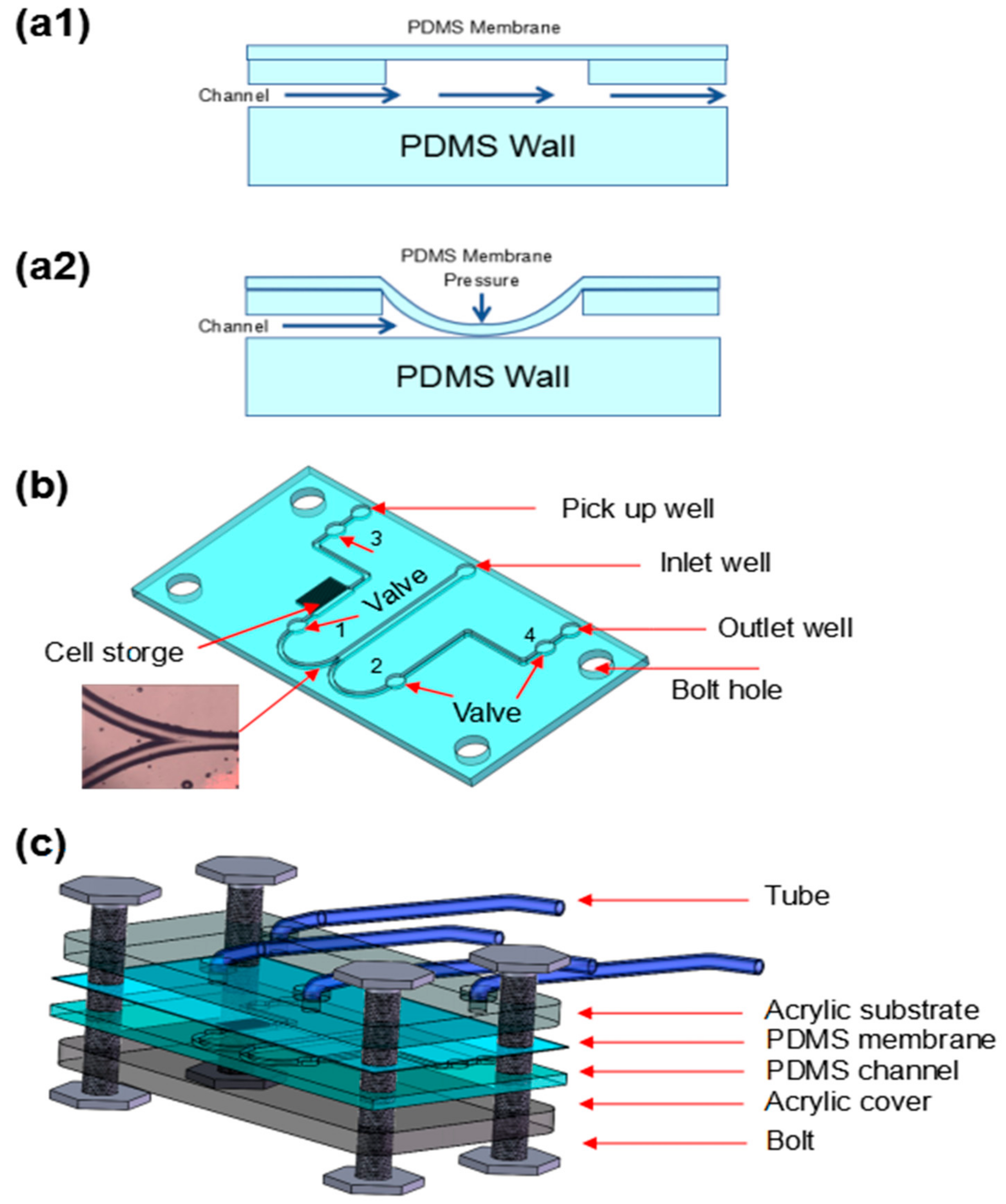
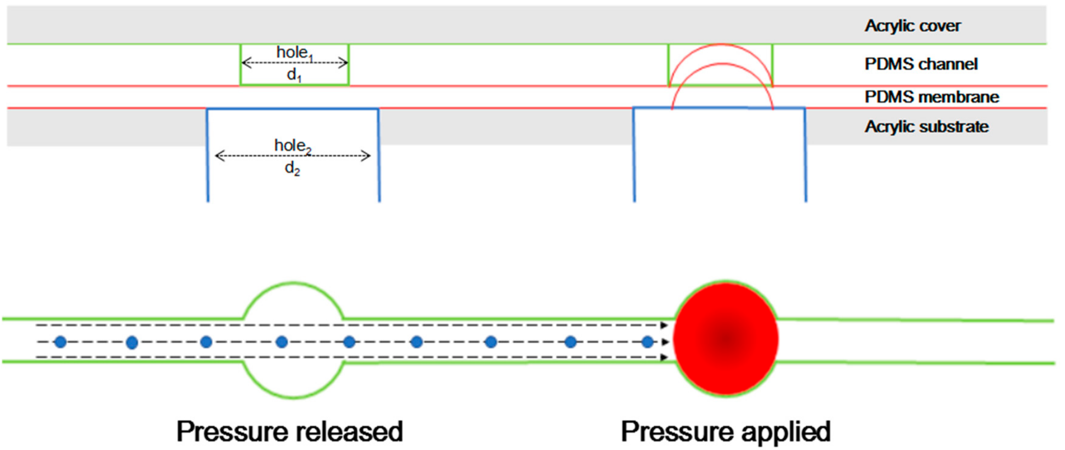
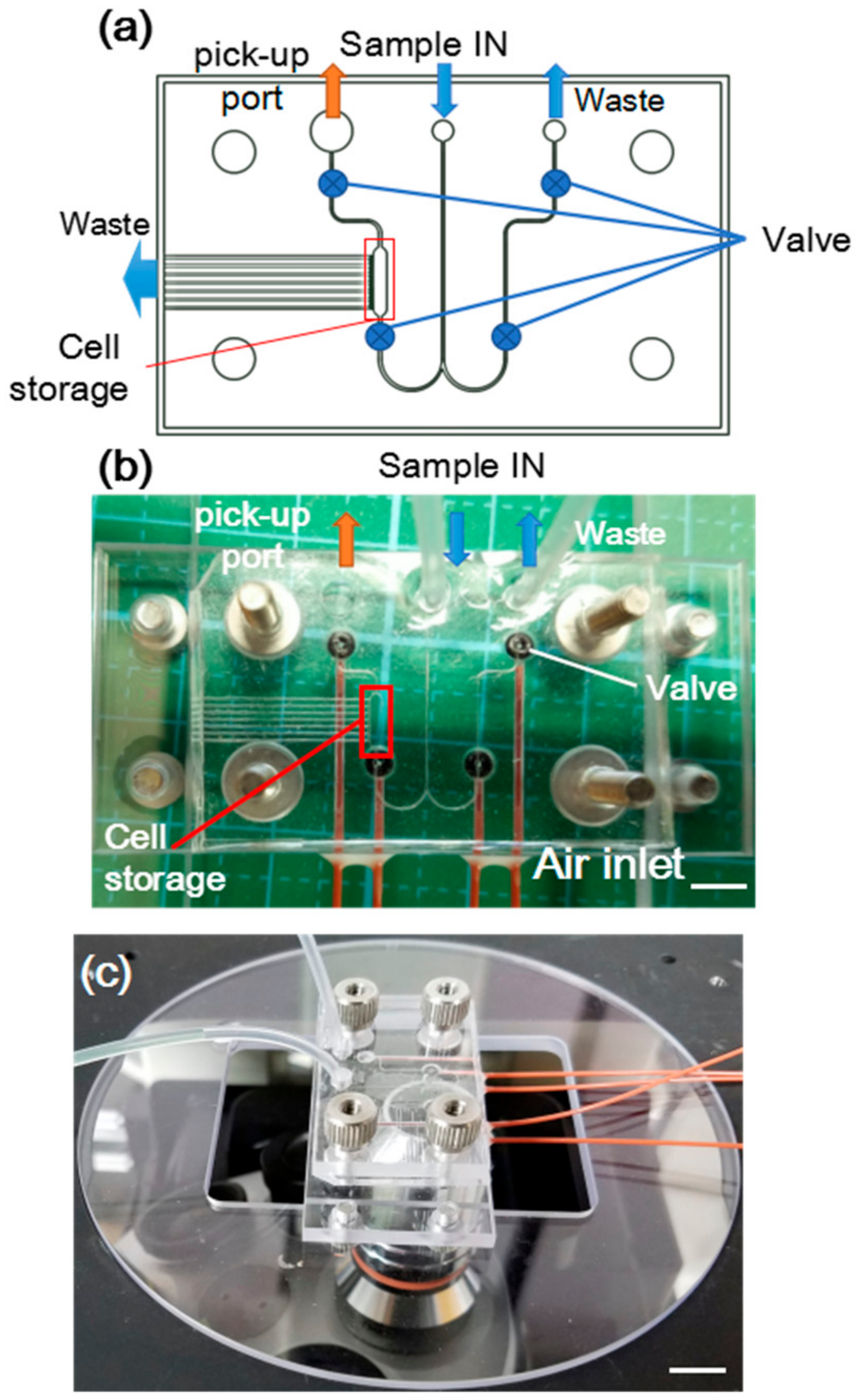
2.1. Design and Fabrication of PDMS Membrane Integrated Microfluidic Device

The microfluidic device was designed based on an application for capturing, observation and collecting larger biological objects. The bio-object Euglena is important biological research target for multiple purposes [54,55]. However, observing and retrieving few (<10) Euglena is typical in experiments that perform Euglena culturing separately. Therefore, without using a complex system, we designed the microfluidic device using 4 PDMS membrane valves and a gap-integrated cell storage (Figure 1) to capture, observe and retrieve Euglena. Euglena gracilis was generously provided by Euglena Co. Ltd. (Tokyo, Japan).
As shown in Figure 1(a1,a2), 4 typical valves based on a PDMS membrane were integrated into a microfluidic channel. When pressure was applied, the PDMS membrane was deflected to close the channel. The structure of the microfluidic channel was illustrated in Figure 1b. The width and depth of the main channels were 200 and 100 μm, respectively. There was an inlet well, an outlet, a cell storage, and a pick-up well. An inlet well was used to introduce the sample. An outlet was used to collect the waste. A cell storage which was used to collect the target sample and a pick-up well was used for retrieving the collected sample. Importantly, in the microfluidic channel, there were four holes and each hole was coupled with a valve of 500-μm diameter which could control the direction of the fluid flow.
As shown in Figure 1c, the whole structure of this valve device actuated by PDMS membrane was consisted of four layers (from bottom to top, in order to make it clear, the diagram is reversed): an thick acrylic substrate layer, a PDMS membrane actuator as one part of the valve, a PDMS microfluidic layer with micro channel structures and valves on the upper side, and a thick acrylic cover layer.
The PDMS channel was fabricated by the soft lithography method. The master for rapid prototyping of the PDMS microstructure was fabricated using a negative photo resist (Su-8 3050, Tokyo Ohka Kogyo, Tokyo, Japan) on a silicon wafer (4-inch diameter). Once the silicon master was obtained, we started the PDMS replicating process. The PDMS kit (SYLGARD 184, Dow Corning, Midland, MI, USA) was used. The liquid pre-polymer base and cross-linking agents were mixed at a ratio of 10:1 by weight. Then, mixed PDMS was poured over the master to create a layer of 2-mm thickness and heated at 80 °C in an oven for 1 h. The cured PDMS was then carefully peeled off from the mold and trimmed to the suitable size.
To investigate the performance of PDMS membranes in different thicknesses, we fabricated PDMS membranes in 6 types of thickness. To control the thickness of PDMS, we used a specific rotation speed of spin-coater for coating PDMS on silicon wafer.
The thick acrylic substrate layer was fabricated to hold and actuate the membrane valves. On the acrylic substrate, there were four drilled holes with the diameter of 800 μm. Each hole was connected to a solenoid-controlled valve that was connected to an air-compressor through polyetheretherketone (PEEK) tubes. The thick acrylic cover layer was employed to ensure the vision of the device. We used an acrylic plate (40 mm × 25 mm × 2 mm) with 4 drilled holes of 3-mm diameter to hold the structure. All four layers were held together by a bolt through the 3-mm holes to prevent any leakage.

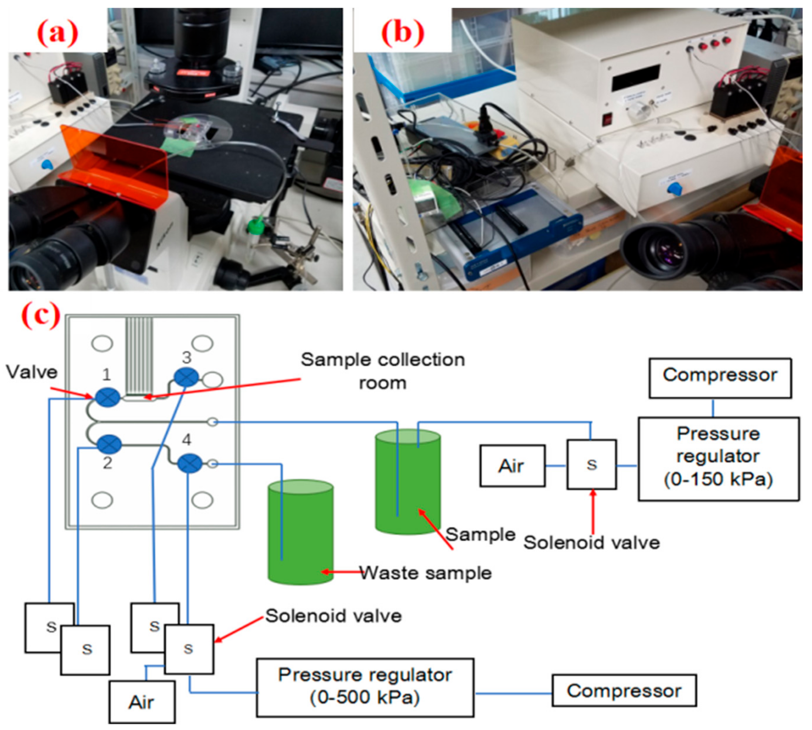
2.2. Experiment Setting and Method

The whole device was mounted on a reversed microscope (IX71, Nikon, Tokyo, Japan) and the image was captured by a charge-coupled device (CCD) camera (Nikon 1 V1, Nikon).

2.2.1. Simulation Conditions

To investigate the performance of the developed device of the PDMS membrane-actuated valve, a numerical simulation was performed to design the optimized membrane and to investigate the deflection of the PDMS membrane. The deflection was simulated numerically using commercial software (COMSOL, COMSOL Inc., Stockholm, Sweden). During the simulation, the density (ρ), Young module (E), and Poisson ratio (ν) of the PDMS were set at 970 kg/m3, 750 KPa [3], and 0.5, respectively. The boundary conditions are shown in Figure S1.

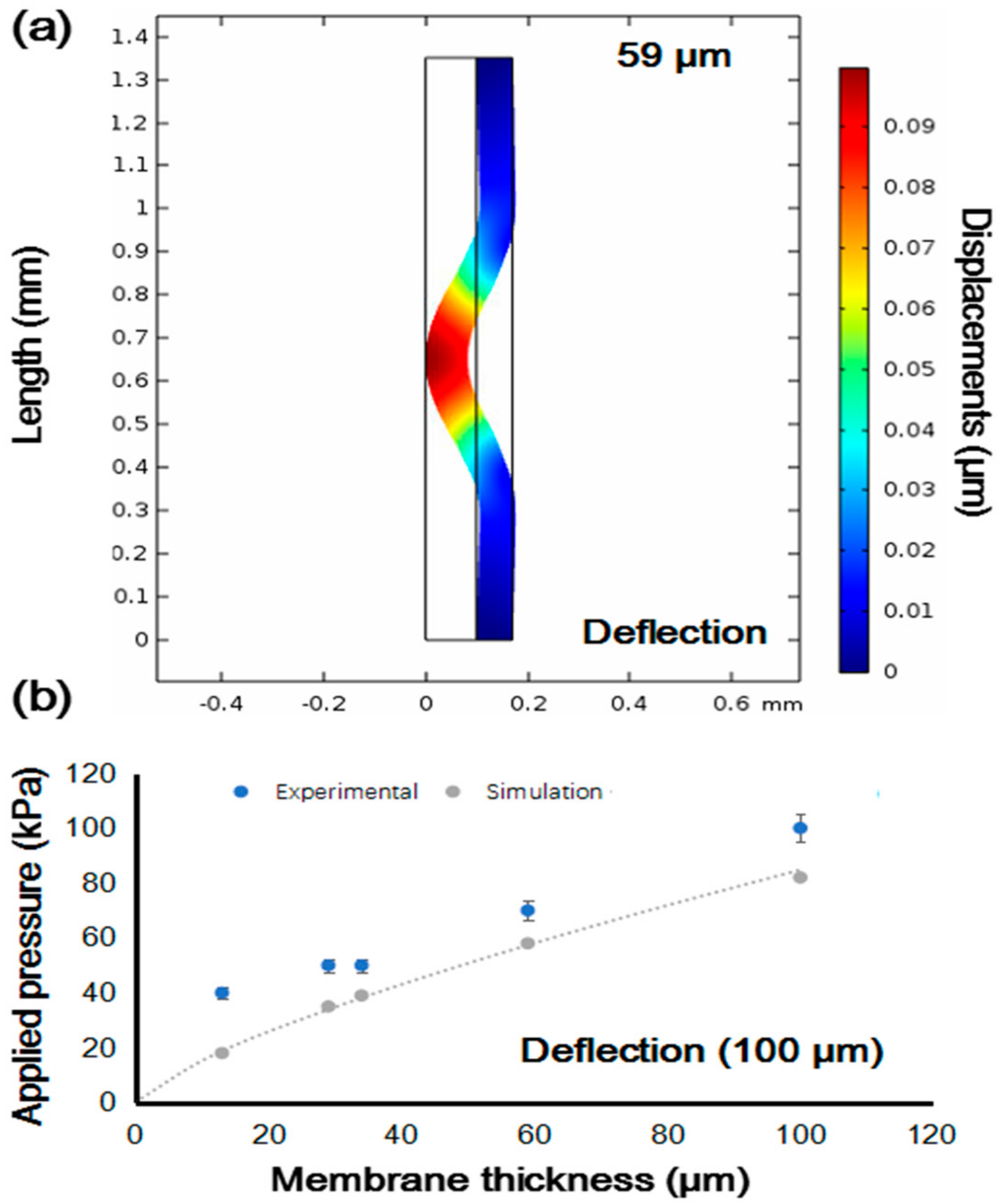
2.2.2. Applied Pressure versus Deflection of Valve Structure

The function of the valve is based on a flexible PDMS membrane that is deflected to actuate (open or close) the valve on demand. The diameter of the valve was decided based on the size of Euglena (50–100 µm). In previous reports [37,56], the size of orifice (100–200 μm) was decided from the size of the target cells (10–20 µm) that corresponded to a five to ten-fold difference. Therefore, we selected 500 µm as the diameter of valve. Figure 2 illustrates actuation mechanisms of the PDMS membrane. As shown in Figure 2, there is a hole1 (d1 = 500 μm) on the microfluidic channel. Under the microfluidic channel, a thin PDMS membrane is set. At the same time, in the acrylic substrate layer, there is a hole2 (d2 = 800 μm) under each hole1 and the two holes are separated by the membrane in the middle layer. The holes on acrylic substrate were connected to the compressor (DA-60S, ULVAC, Tokyo, Japan) which supplies the air pressure for the control of the PDMS membrane valve through tubes. To close the channel more securely, the size of the holes under the membrane should be larger than the holes above the membrane [26]. When the valve is connected to air, the PDMS membrane is not deflected and the valve is kept open. When the valve is connected to a compressor and pressure is applied, the PDMS membrane is deflected and pressed against the opening of the top acrylic layer to close the valve.
To explore the relationship between the thickness and the deflection of the PDMS membrane, we also fabricated different thicknesses of PDMS membranes to apply different pressures to investigate their deflection. To obtain different thicknesses of PDMS membranes, base and curing agents of PDMS were mixed at a ratio of 10:1 by weight and spun on the substrate previously described. Varying the rotational speed and time to tune the thickness [57], spin-coated PDMS was baked in an oven at 60 °C for 1 h. Since a membrane 12.7 μm thick could not be retrieved after being heated at 80 °C, all membranes were cured by 60 °C for comparison in equal conditions of membrane preparation. A spin coater (1H-D7, MIKASA, Hiroshima, Japan) was used to apply 30–1200 rpm to form PDMS membranes with various thickness. Table 1 and Figure S2 show the thickness of the PDMS membrane and its corresponding rotational speed. The values of membrane thickness were the average values calculated from measurements on three different points of the PDMS membranes. The thickness was measured by a measuring microscope (MF-B1010C, Mitutoyo, Tokyo, Japan) with a CCD camera unit (Lu075C, Lumenera, Ottawa, ON, Canada). To investigate the relationship between membrane thickness and measuring position, we first measured the three points (defined as position A) on the membranes as shown in Figure S3a and then measured the thickness of four points at positions of valves (defined as position B) as shown in Figure S3b. All data were collected from three PDMS membranes at each condition of rotation. The results for positions A and B are shown in Table 1 and Table 2, respectively. The maximum difference between thickness at position A and position B was less than 4 µm (rotational speed of 30 rpm), and the minimum difference was 1 µm (rotational speed of 1200 rpm) (Figure S4). The difference was possibly induced by measuring error or other unavoidable environmental conditions such as temperature and humidity.

2.2.3. Applied Pressure and Device Performance

To demonstrate the PDMS membrane deflection and measure the property of the membrane, this study also used the PDMS membrane as a valve actuator.
Figure 3a shows the constructed on-chip actuator system with pneumatically actuated valve. The microfluidic chip was set on a microscope. Pneumatical actuators were then fixed to the microfluidic chip using supporting attachments. The sample suspension was introduced by a compressor that is shown in Figure 3b. The overall system of a pneumatically actuated PDMS-membrane valve is shown in detail in Figure 3c. There were 4 PDMS valves electronically controlled by 4 solenoid valves. The sample was introduced by using an air pump and controlled by another solenoid valve. We had 2 compressors to control solenoid for inlet and valves, respectively.

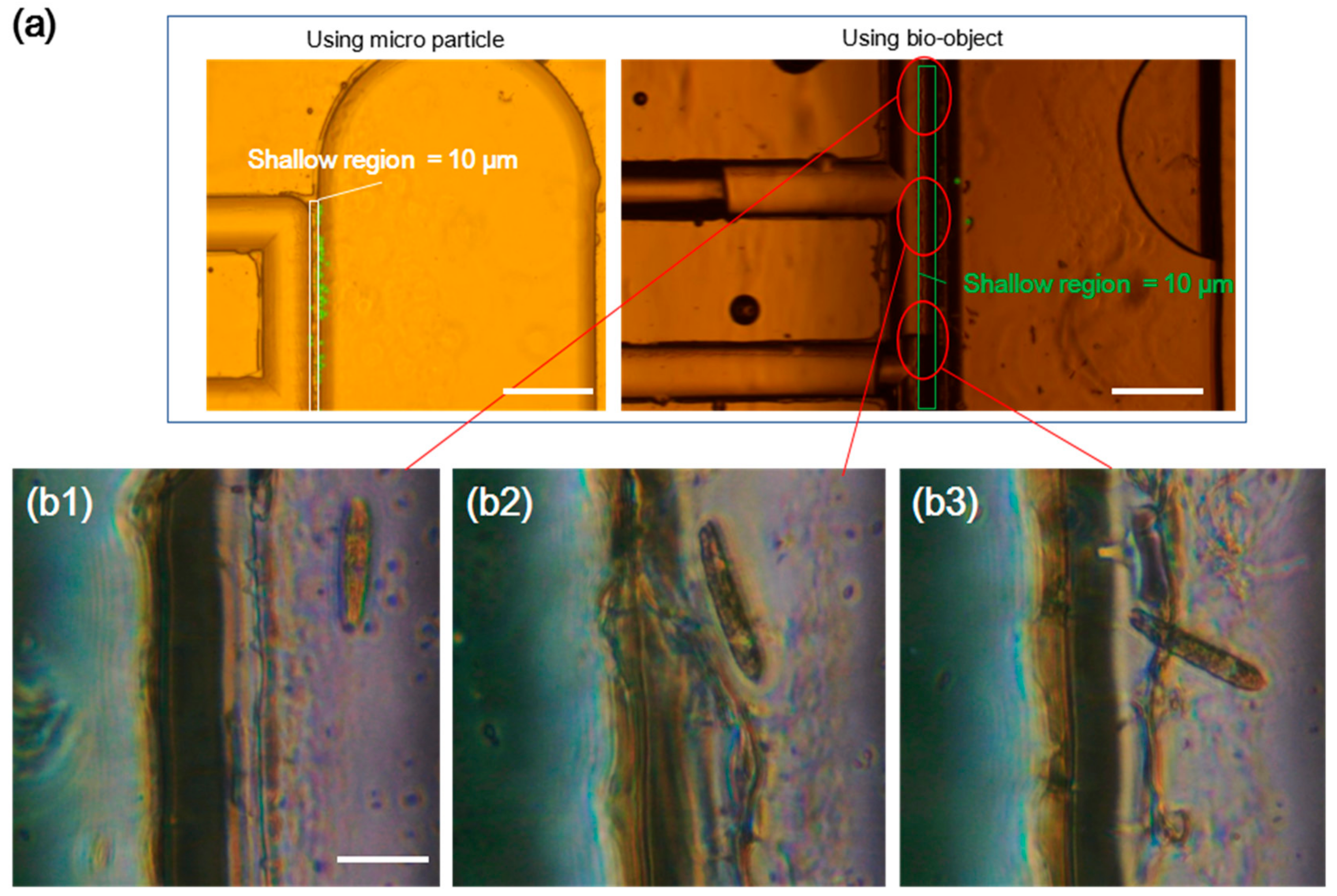
2.2.4. Demonstration of Cell Capturing by Using the PDMS-Membrane Actuator

To confirm the function of PDMS membrane as an actuator in practical use, we designed a conceptual device for cell capturing as shown in Figure 1b. We used valve 1 and 2 to capture the target cell, Euglena, and valve 3 for retrieving captured Euglena. Valve 4 was kept open in general; it was closed to prevent losing samples only when Euglena escaped from the image recognition area (Figure S5a). Compared with other methods [56], the proposed device aimed to work with relatively large cells with high mobility. The structure of a retrievable cage was required to maintain cells in healthy and active condition. In addition, the proposed device was intended not only for capturing cells but also for using a gap structure to concentrate the density of the captured cells without losing samples. The function of PDMS gap with 10-µm height (Figure S5b,c) was confirmed by introducing microparticles of 20-µm diameter (Polystyrene Microspheres, Polysciences, Warrington, PA, USA) in 1000-times diluted suspension liquid at a flow pressure of 10 kPa.

3. Results and Discussion

3.1. Simulation Results and Calculations

The simulation results are shown in Figure 4. We first found appropriate pressure to close the channel and to make the velocity in the channel 0 m/s. Then, we used this pressure to simulate deflection of the PDMS membrane with various thicknesses. Figure 4a shows the results of simulated deflection of a 59-μm membrane that shows a typical pattern of deflection. As summarized in Figure 4b, thicker PDMS membrane required more pressure to close the channel. Comparing the values of simulated pressure with the values of actual pressure required to close the valve, we found that our valve required more pressure to close the channel in the experiments than when using the simulated pressure. The results indicate that mechanical properties such as stress, hardness, and tensile strength of our PDMS membrane were different from the typical values. The possible reasons could be a small but not negligible difference in baking time, mixing rate error, and location of fabrication (humidity and temperature).

3.2. Prototype Devices

As shown in Figure 5, a prototype device was fabricated. The cell storage used a shallow gap structure to capture cells and release the extra media. By controlling 4 valves, it was ensured that only cells were selected and transferred to cell storage. In order to retrieve the collected cells, 2 valves adjacent to the cell storage were open to release the cells.

3.3. Applied Pressure and Deflection of Valve Structure

Several experiments were conducted for investigating the effects of the PDMS-membrane valve and the consequences for all pneumatically driven PDMS valves. As shown in Table 3, with the increase of the thickness of the PDMS membrane, the minimal pressure to close the valve also increased. Therefore, for further experiments, a membrane with a thickness of 29 µm was used based on the results of calculation and for convenience of handling.
Increasing the thickness of the PDMS membrane meant that the minimal pressure to close valve also increased. In order to operate the PDMS-membrane valve conveniently and flexibly, the PDMS membrane should be thinner. However, as Goldowsky and Knapp [26] found when implementing a valve of thin-membrane PDMS, applying high pressures to the valve could be problematic. Since PDMS was permeable to gases, it could cause failure of the valve because gas bubbles could be formed inside the fluidic channels of the system. These bubbles prevented employing PDMS as a valve in many applications. Therefore, when the PDMS membrane is used as a valve, the supplied pressure should be larger to close the channel more securely, but the pressure should not be too large to avoid the break and over deflection of the PDMS membrane, as summarized above.

3.4. Applied Pressure and Device Performance

We used the PDMS-membrane valve to control the fluid flow in a micro channel for evaluating the performance of the device. The video (Video S1) showed the behavior of the PDMS-membrane valve. As demonstrated in the beginning of the video, PDMS membrane did not deflect, and valves on both branches were kept open, so the fluid could flow into both branches when the valves were connected to air. When valves were connected to a compressor and pressure was applied, in the latter part of the video, the PDMS membrane deflected and the valves were closed, so the fluid stopped flowing. Then, connecting the upper valve to the air, the upper valve opened and the fluid flowed into the upper branch. From this video, we confirmed the good performance of the PDMS-membrane valve.

3.5. Demonstration of Capturing Cells Using the PDMS-Membrane Actuator

We conducted a demonstration of capturing cells using the device equipped with PDMS-membrane actuator. The valves functioned at 50 KPa and performed normally without leakage. The response time was less than 30 ms due to the property of our camera. The sequence of valve function was carefully considered to avoid losing the sample during the capturing process. Only valve 1 and 2 were actively controlled in this demonstration. Valve 3 was kept closed and valve 4 was set to open. Two types of objects, 20-µm diameter micro particles and Euglena, were successfully isolated and captured in the chamber of cell storage with shallow gap structure (Figure 6a). The enlarged view of the cell storage (Figure 6(b1–b3)) indicated the captured Euglena. In the right image of Figure 6a, because of the gas permeability of PDMS, some bubbles generated by valve actions flowed into the capturing chamber. These small bubbles slowly gathered to form a big bubble. However, this problem would be avoided by using a thicker PDMS membrane.

4. Conclusions

In this paper, the effects of deflecting PDMS membrane on the application of pneumatically driven valves made of thin replaceable PDMS membrane were investigated. It was shown that deflection of PDMS membrane was influenced by the thickness of the membrane and applied pressure. By increasing the thickness of PDMS membrane, the pressure to close valve increased simultaneously. In order to operate the PDMS-membrane valve conveniently and flexibly, PDMS membrane is desired to be in the appropriate range of thickness. We also verified appropriate range of applied pressure to deflect PDMS without generating air bubbles in microfluidics. Finally, we demonstrated that the PDMS membrane functioned as a valve actuator in a Euglena-capturing device. We expect that this study would work as an important reference for research using PDMS membrane as an actuator and a replaceable component of microfluidics.

Supplementary Materials

The following are available online at https://www.mdpi.com/2076-0825/7/4/68/s1, Figure S1: Geometry for simulation and calculating domain, Figure S2: The thickness of the PDMS membrane and its corresponding rotational speed. Figure S3: Measuring points for average thickness of PDMS membrane. Figure S4: Comparison of membrane thickness measured at position A and B. Figure S1: Images of gap structure integrated cell storage unit. Video S1: Video of valve motion. (Available online: https://youtu.be/ZGkmp1kVUhc)

Author Contributions

Y.T. and Y.Ya. conceived and designed the experiments; Y.Ya. and N.O. performed the experiments; Y.Yu., Y.Ya. and N.O. wrote the paper. All authors discussed on the experimental results.

Funding

This work was supported by JSPS KAKENHI grant No. 18K18792 (Challenging Research (Exploratory)) and TEPCO Memorial Foundation, Japan.

Acknowledgments

The authors thank Euglena Co. Ltd. (Tokyo, Japan) for generously providing the Euglena gracilis used in this research.

Conflicts of Interest

The authors declare no conflicts of interest.

References

  1. Becker, H.; Locascio, L.E. Polymer microfluidic devices. Talanta 2002, 56, 267–287. [Google Scholar] [CrossRef]
  2. Madadi, H.; Mohammadi, M.; Casals-Terré, J.; López, R.C. A novel fabrication technique to minimize poly(dimethylsiloxane)-microchannels deformation under high-pressure operation. Electrophoresis 2013, 34, 3126–3132. [Google Scholar] [CrossRef] [PubMed]
  3. Khanafer, K.; Duprey, A.; Schlicht, M.; Berguer, R. Effects of strain rate, mixing ratio, and stress-strain definition on the mechanical behavior of the polydimethylsiloxane (PDMS) material as related to its biological applications. Biomed. Microdevices 2009, 11, 503–508. [Google Scholar] [CrossRef] [PubMed]
  4. Rogers, J.A.; Nuzzo, R.G. Recent progress in soft lithography. Mater. Today 2005, 8, 50–56. [Google Scholar] [CrossRef]
  5. Ren, D.H.; Xia, Y.; Wang, J.; You, Z. Micropatterning of single cell arrays using the PEG-Silane and Biotin-(Strept)Avidin System with photolithography and chemical vapor deposition. Sens. Actuators B Chem. 2013, 188, 340–346. [Google Scholar] [CrossRef]
  6. Mcdonald, J.C.; Duffy, D.C.; Anderson, J.R.; Chiu, D.T. Review General Fabrication of microfluidic systems in poly(dimethylsiloxane). Electrophoresis 2000, 21, 27–40. [Google Scholar] [CrossRef]
  7. Harrison, D.J.; Fluri, K.; Seiler, K.; Fan, Z.; Effenhauser, C.S.; Manz, A. Micromachining a Miniaturized Capillary Electrophoresis-Based Chemical Analysis System on a Chip. Science 2016, 261, 895–897. [Google Scholar] [CrossRef] [PubMed]
  8. Zhang, W.; Zhang, H.; Williams, S.E.; Zhou, A. Microfabricated three-electrode on-chip PDMS device with a vibration motor for stripping voltammetric detection of heavy metal ions. Talanta 2015, 132, 321–326. [Google Scholar] [CrossRef] [PubMed]
  9. Kunstmann-Olsen, C.; Hanczyc, M.M.; Hoyland, J.; Rasmussen, S.; Rubahn, H.G. Uniform droplet splitting and detection using Lab-on-Chip flow cytometry on a microfluidic PDMS device. Sens. Actuators B Chem. 2016, 229, 7–13. [Google Scholar] [CrossRef]
  10. Tian, Z.; Ren, D.; You, Z. Self-oscillation-based frequency tracking for the drive and detection of resonance magnetometers. Sensors 2016, 16. [Google Scholar] [CrossRef] [PubMed]
  11. Stroock, A.D.; Whitesides, G.M. Components for integrated poly(dimethylsiloxane) microfluidic systems. Electrophoresis 2002, 23, 3461–3473. [Google Scholar]
  12. Yoon, Y.; Lee, D.W.; Lee, J.B. Fabrication of optically transparent PDMS artificial lotus leaf film using underexposed and underbaked photoresist mold. J. Microelectromech. Syst. 2013, 22, 1073–1080. [Google Scholar] [CrossRef]
  13. Merkel, T.C.; Bondar, V.I.; Nagai, K.; Freeman, B.D.; Pinnau, I. Gas sorption, diffusion, and permeation in poly(dimethylsiloxane). J. Polym. Sci. Part B Polym. Phys. 2000, 38, 415–434. [Google Scholar] [CrossRef] [Green Version]
  14. Delamarche, E.; Schmid, H.; Michel, B.; Biebuyck, H. Patterned Delivery of Immunoglobulins to Surfaces Using Microfluidic Networks Patterned Delivery of Immunoglobulins to Surfaces Using Microfluidic Networks. Science 2013, 779, 779–782. [Google Scholar]
  15. Whitesides, G.M.; Ostuni, E.; Jiang, X.; Ingber, D.E. Soft L Ithography in Biology and Biochemistry. Annu. Rev. Biomed. Eng. 2001, 3, 335–373. [Google Scholar] [CrossRef] [PubMed]
  16. Kane, R.S.; Takayama, S.; Ostuni, E.; Ingber, D.E.; Whitesides, G.M. Patterning proteins and cells using soft lithography. Biomaterials 1999, 20, 2363–2376. [Google Scholar] [CrossRef]
  17. Hua, Z.; Xia, Y.; Srivannavit, O.; Rouillard, J.-M.; Zhou, X.; Gao, X.; Gulari, E. A versatile microreactor platform featuring a chemical-resistant microvalve array for addressable multiplex syntheses and assays. J. Micromech. Microeng. 2006, 16, 1433–1443. [Google Scholar] [CrossRef]
  18. Li, M.; Li, W.H. 1999 Duffy Whitesides Rapid prototyping of microfluidic switches in poly(dimethyl siloxane) and their actuation by electro-osmotic flow. J. Micromech. Microeng. 1999, 9, 211–217. [Google Scholar]
  19. Ismagilov, R.F.; Rosmarin, D.; Kenis, P.J.A.; Chiu, D.T.; Zhang, W.; Stone, H.A.; Whitesides, G.M. Pressure-driven laminar flow in tangential microchannels: An elastomeric microfluidic switch. Anal. Chem. 2001, 73, 4682–4687. [Google Scholar] [CrossRef] [PubMed]
  20. Unger, M.A.; Unger, M.A.; Chou, H.; Thorsen, T.; Scherer, A.; Quake, S.R. Monolithic Microfabricated Valves and Pumps by Multilayer Soft Lithography. Science 2013, 113, 113–117. [Google Scholar] [CrossRef]
  21. Zhang, W.; Lin, S.; Wang, C.; Hu, J.; Li, C.; Zhuang, Z.; Zhou, Y.; Mathies, R.A.; Yang, C.J. PMMA/PDMS valves and pumps for disposable microfluidics. Lab Chip 2009, 9, 3088–3094. [Google Scholar] [CrossRef] [PubMed]
  22. Grover, W.H.; Ivester, R.H.C.; Jensen, E.C.; Mathies, R.A. Development and multiplexed control of latching pneumatic valves using microfluidic logical structures. Lab Chip 2006, 6, 623–631. [Google Scholar] [CrossRef] [PubMed]
  23. Grover, W.H.; Skelley, A.M.; Liu, C.N.; Lagally, E.T.; Mathies, R.A. Monolithic membrane valves and diaphragm pumps for practical large-scale integration into glass microfluidic devices. Sens. Actuators B Chem. 2003, 89, 315–323. [Google Scholar] [CrossRef]
  24. Lagelly, E.T.; Scherer, J.R.; Blazej, R.G.; Toriello, N.M.; Diep, B.A.; Ramchandani, M.; Sensabaugh, G.F.; Riley, L.W.; Mathies, R.A. Integrated portable genetic analysis microsystem for pathogen/infectious disease detection. Anal. Chem. 2004, 76, 3162–3170. [Google Scholar] [CrossRef] [PubMed]
  25. Karlinsey, J.M.; Monahan, J.; Marchiarullo, D.J.; Ferrance, J.P.; Landers, J.P. Pressure injection on a valved microdevice for electrophoretic analysis of submicroliter samples. Anal. Chem. 2005, 77, 3637–3643. [Google Scholar] [CrossRef] [PubMed]
  26. Goldowsky, J.; Knapp, H.F. Gas penetration through pneumatically driven PDMS micro valves. RSC Adv. 2013, 3, 17968–17976. [Google Scholar] [CrossRef]
  27. Hosokawa, K.; Maeda, R. A pneumatically-actuated three-way microvalve fabricated with polydimethylsiloxane using the membrane transfer technique. J. Micromech. Microeng. 2000, 10, 415–420. [Google Scholar] [CrossRef]
  28. Amin, A.M.; Wereley, S.T.; Thottethodi, M.; Vijaykumar, T.N.; Jacobson, S.C. Polydimethylsiloxane (pdms) peristaltic pump characterization for programmable lab-on-a-chip applications. In Proceedings of the Twelfth International Conference on Miniaturized Systems for Chemistry and Life Sciences, San Diego, CA, USA, 12–16 October 2008; pp. 1681–1683. [Google Scholar]
  29. Cheng, Z.; Wu, X.; Cheng, J.; Liu, P. Microfluidic fluorescence-activated cell sorting (μFACS) chip with integrated piezoelectric actuators for low-cost mammalian cell enrichment. Microfluid. Nanofluid. 2017, 21, 1–11. [Google Scholar] [CrossRef]
  30. Wang, C.H.; Lee, G. Bin Pneumatically driven peristaltic micropumps utilizing serpentine-shape channels. J. Micromech. Microeng. 2006, 16, 341–348. [Google Scholar] [CrossRef]
  31. Chiou, C.H.; Yeh, T.Y.; Lin, J.L. Deformation analysis of a pneumatically-activated polydimethylsiloxane (PDMS) membrane and potential micro-pump applications. Micromachines 2015, 6, 216–229. [Google Scholar] [CrossRef]
  32. Tseng, H.Y.; Wang, C.H.; Lin, W.Y.; Lee, G. Bin Membrane-activated microfluidic rotary devices for pumping and mixing. Biomed. Microdevices 2007, 9, 545–554. [Google Scholar] [CrossRef] [PubMed]
  33. Eddings, M.A.; Gale, B.K. A PDMS-based gas permeation pump for on-chip fluid handling in microfluidic devices. J. Micromech. Microeng. 2006, 16, 2396–2402. [Google Scholar] [CrossRef]
  34. Li, G.; Luo, Y.; Chen, Q.; Liao, L.; Zhao, J. A “place n play” modular pump for portable microfluidic applications. Biomicrofluidics 2012, 6, 14118–1411816. [Google Scholar] [CrossRef] [PubMed]
  35. Kim, Y.C.; Kang, J.H.; Park, S.-J.; Yoon, E.-S.; Park, J.-K. Compressive Cell Stimulation using PDMS Membrane Deflection in a Microfluidic Device. In Proceedings of the TRANSDUCERS 2007—2007 International Solid-State Sensors, Actuators and Microsystems Conference, Lyon, France, 10–14 June 2007; pp. 1873–1876. [Google Scholar]
  36. Murphy, C.T.; Hu, P.J. Microfluidics as a tool for C. elegans research. WormBook 2013, 1–30. [Google Scholar] [CrossRef] [PubMed]
  37. Irimia, D.; Toner, M. Cell handling using microstructured membranes. Lab Chip 2006, 6, 345–352. [Google Scholar] [CrossRef] [PubMed]
  38. Leclerc, E.; Sakai, Y.; Fujii, T. Cell culture in 3-dimensional microfluidic structure of PDMS (polydimenthylsiloxane). Biomed. Microdevices 2003, 5, 109–114. [Google Scholar] [CrossRef]
  39. Ho, K.K.Y.; Lee, L.M.; Liu, A.P. Mechanically activated artificial cell by using microfluidics. Sci. Rep. 2016, 6, 32912. [Google Scholar] [CrossRef] [PubMed] [Green Version]
  40. Wang, Y.C.; Tsai, Y.C.; Shih, W.P. Flexible PDMS micro-lens array with programmable focus gradient fabricated by dielectrophoresis force. Microelectron. Eng. 2011, 88, 2748–2750. [Google Scholar] [CrossRef]
  41. Schneider, F.; Draheim, J.; Müller, C.; Wallrabe, U. Optimization of an adaptive PDMS-membrane lens with an integrated actuator. Sens. Actuators A Phys. 2009, 154, 316–321. [Google Scholar] [CrossRef]
  42. Yu, H.; Zhou, G.; Leung, H.M.; Chau, F.S. Tunable liquid-filled lens integrated with aspherical surface for spherical aberration compensation. Opt. Express 2010, 18, 9945–9954. [Google Scholar] [CrossRef] [PubMed]
  43. Choi, H.; Han, D.S.; Won, Y.H. Fluidic lens of PDMS membrane driven by voice-coil and magnet. IEEE Photonics Technol. Lett. 2012, 24, 1683–1685. [Google Scholar] [CrossRef]
  44. Zhai, Y.; Wang, A.; Koh, D.; Schneider, P.; Oh, K.W. A robust, portable and backflow-free micromixing device based on both capillary- and vacuum-driven flows. Lab Chip 2018, 2, 276–284. [Google Scholar] [CrossRef] [PubMed]
  45. Song, Q.H.; Zhu, W.M.; Zhang, W.; Wu, P.C.; Shen, Z.X.; Yang, Z.C.; Jin, Y.F.; Hao, Y.L.; Bourouina, T.; Leprince-Wang, Y.; et al. Tunable metamaterial lens array via metadroplets. In Proceedings of the 2015 28th IEEE International Conference on Micro Electro Mechanical Systems (MEMS), Estoril, Portugal, 18–22 January 2015; pp. 960–963. [Google Scholar]
  46. Gervais, T.; El-Ali, J.; Günther, A.; Jensen, K.F. Flow-induced deformation of shallow microfluidic channels. Lab Chip 2006, 6, 500–507. [Google Scholar] [CrossRef] [PubMed]
  47. Hardy, B.S.; Uechi, K.; Zhen, J.; Pirouz Kavehpour, H. The deformation of flexible PDMS microchannels under a pressure driven flow. Lab Chip 2009, 9, 935–938. [Google Scholar] [CrossRef] [PubMed]
  48. Kang, C.K.; Overfelt, R.A.; Roh, C. Deformation properties between fluid and periodic circular obstacles in polydimethylsiloxane microchannels: Experimental and numerical investigations under various conditions. Biomicrofluidics 2013, 7, 1–15. [Google Scholar] [CrossRef] [PubMed]
  49. Lötters, J.C.; Olthuis, W.; Veltink, P.H.; Bergveld, P. The Mechanical Properties of the Rubber Elastic Polymer Polydimethilsiloxane for Sensor Applications. J. Micromech. Microeng. 1997, 7, 145–147. [Google Scholar] [CrossRef]
  50. Liu, M.; Sun, J.; Sun, Y.; Bock, C.; Chen, Q. Thickness-dependent mechanical properties of polydimethylsiloxane membranes. J. Micromech. Microeng. 2009, 19, 035028. [Google Scholar] [CrossRef]
  51. Johnston, I.D.; McCluskey, D.K.; Tan, C.K.L.; Tracey, M.C. Mechanical characterization of bulk Sylgard 184 for microfluidics and microengineering. J. Micromech. Microeng. 2014, 24, 035017. [Google Scholar] [CrossRef]
  52. Lamberti, A.; Marasso, S.L.; Cocuzza, M. PDMS membranes with tunable gas permeability for microfluidic applications. RSC Adv. 2014, 4, 61415–61419. [Google Scholar] [CrossRef]
  53. Firpo, G.; Angeli, E.; Repetto, L.; Valbusa, U. Permeability thickness dependence of polydimethylsiloxane (PDMS) membranes. J. Membr. Sci. 2015, 481, 1–8. [Google Scholar] [CrossRef]
  54. Schmid, G.H.; Thibault, P. Studies on the s-state distribution in euglena gracilis. Z. Naturforsch. Sect. C J. Biosci. 1983, 38, 60–66. [Google Scholar]
  55. Bound, K.E.; Tollin, G. Phototactic Response of Euglena gracilis to Polarized Light. Nature 1967, 216, 1042–1044. [Google Scholar] [CrossRef]
  56. Zhou, Y.; Basu, S.; Wohlfahrt, K.J.; Lee, S.F.; Klenerman, D.; Laue, E.D.; Seshia, A.A. A microfluidic platform for trapping, releasing and super-resolution imaging of single cells. Sens. Actuators B Chem. 2016, 232, 680–691. [Google Scholar] [CrossRef] [PubMed] [Green Version]
  57. Jadav, G.L.; Aswal, V.K.; Bhatt, H.; Chaudhari, J.C.; Singh, P.S. Influence of film thickness on the structure and properties of PDMS membrane. J. Membr. Sci. 2012, 415–416, 624–634. [Google Scholar] [CrossRef]
Figure 1. The principle, design and layer structure of the device. (a1) Polydimethylsiloxane (PDMS) membrane-actuated valve structure. (a2) PDMS membrane-actuated valve structure with applied pressure. The channel was closed by the deflected membrane. (b) The channel layer of the cell capturing device. The branch is the image recognition area for capturing Euglena. (c) Layered illustration of the device of PDMS membrane-actuated valve.
Actuators 07 00068 g001
Figure 2. The schematic design of the cross section of the microfluidic device. This device consisted of 4 layers.
Actuators 07 00068 g002
Figure 3. Experimental setup for demonstration of PDMS membrane that actuated cell-capturing device. (a) Actual setup of the device. (b) Fluidic connection and control of the device. (c) The principle of control and connection system of the cell-capturing device.
Actuators 07 00068 g003
Figure 4. Simulation results of required closing pressure for deflection of membrane in different thickness. (a) Deflection of membrane with 59-µm thickness. Simulation used the pressure applied to the membrane to close the channel and make the velocity to 0 m/s. (b) Correlation between membrane thickness and applied pressure, and correlation between simulated closing pressure and experimental pressure.
Actuators 07 00068 g004
Figure 5. Prototype of cell capturing device equipped with PDMS membrane actuator. (a) Design of the device. (b) Prototype device with 4 air inlets, 1 sample inlet, 2 waste-outlets and a pick-up port. The scale bar is 5 mm. (c) The fully assembled cell capturing device equipped with PDMS membrane actuator was mounted on a microscope. The scale bar is 10 mm.
Actuators 07 00068 g005
Figure 6. Demonstration results of the cell capturing device equipped with PDMS-membrane actuator. (a) Microparticles of 20-µm diameter and Euglena captured in shallow gap structure. (b1b3) Captured Euglena in the device. The scale bar is 100 µm.
Actuators 07 00068 g006
Table 1. Thickness of the PDMS membrane at position A and its corresponding rotational speeds.
Rotational Speed (rpm)30601203006001200
Average Thickness (μm)71.959.134.129.018.012.7
Standard Deviation (μm)7.849.111.80.30.9
Table 2. Thickness of the PDMS membrane at position B and its corresponding rotational speeds.
Rotational Speed (rpm)30601203006001200
Average Thickness (μm)77.857.338.632.219.311.1
Standard Deviation (μm)5.39.14.05.62.11.5
Table 3. Minimal pressure to close the valve without bubble generation in different membrane thicknesses.
Thickness of the Membrane (μm)Production Methods of MembraneActuating Pressure of Fluid (KPa)Minimal Pressure to Close Valve (KPa)
13Sylgard 1841040
2950
3450
5970
100NSG-100More than 100

