Mechanical Response of Four-Bar Linkage Microgrippers with Bidirectional Electrostatic Actuation
by
 , , , and
Fabio Botta
1,*,† ,
,
Matteo Verotti
2,
Alvise Bagolini
3,
Pierluigi Bellutti
3 and
Nicola Pio Belfiore
1 1
Department of Engineering, Università degli studi di Roma Tre, 00146 Roma, Italy
2
Università degli studi Niccolò Cusano, 00166 Roma, Italy
3
Micro Nano Fabrication and Characterization Facility, Fondazione Bruno Kessler, 38123 Trento, Italy
*
Author to whom correspondence should be addressed.
†
Current address: via della Vasca Navale 79, 00146 Rome, Italy.
Actuators 2018, 7(4), 78; https://doi.org/10.3390/act7040078
Submission received: 2 October 2018
/
Revised: 19 October 2018
/
Accepted: 7 November 2018
/
Published: 11 November 2018
(This article belongs to the Special Issue Micromanipulation)
Abstract
:This paper presents both an experimental and a numerical study concerning the mechanical response of a silicon microgripper with bidirectional electrostatic actuation to externally applied excitations. The experimental set-up is composed of a probe station equipped with mobile probes that apply contact forces. This part of the investigation aims to test the device’s mechanical resistance, its mobility capability and possible internal contacts during the system deformation. The second part of the paper is dedicated to the study of the free undamped vibrations of the microsystem. Finite Element Analysis (FEA) is carried out to evaluate the system vibration modes. The analysis of the modes are useful to predict possible mechanical interference among floating and anchored fingers of the actuating comb drives.
1. Introduction
The introduction of new classes of flexure hinges [1] and the technological progress in mechanical components of MEMS (micro electro mechanical system) [2,3] gave rise to new devices for the manipulation at the microscale. In fact, about a hundred microgrippers [4,5] were designed and fabricated with different purposes and actuation systems. For example, micromanipulation finds important applications in micro assembly processes. Some devices can be fabricated as monolithical structures, whereas others require an assembly step because of particular geometries or different materials [6]. Microgrippers are also employed in optical fibers assembly [7,8]. Another important field of application is biology: manipulation of single cells is an essential step to understand cells behaviors and interactions [9,10]. For example, microgrippers with force sensors where developed for manipulating biological cells [11,12] or to characterize the mechanical properties of biosamples [13,14]. The sensing [15,16] and the control [17,18] of the gripping forces has also been a fundamental issue in developing microgrippers.
However, in spite of the recent progress in nano and micro-machining, there is still a certain difficulty in building multi-hinge and multi-DoF (Degrees of Freedom) MEMS.
The main problem consists of the fact that mobility is granted by flexure hinges and that the latter are still rather complicated to be designed and fabricated in a small portion of the device. This problem is particularly arduous in the design of microgripper for micro manipulation and, therefore, new microsystems equipped with Conjugate Surface Flexure Hinges (CSFHs) have been developed [19] and fabricated [20]. The idea, which dates back to 2012 [21], is based on the partitioning of a block into either rigid or flexible sub-parts, with mobility being granted by the presence of the flexible parts (flexure). A CSFH is a particular kind of flexure that is made of a curved beam, which provide compliance, and a portion of a conjugate-profiles, which provides accuracy. The two components are designed in such a way that the center of the elastic weights of the curved beam is coincident with the center of the conjugate profiles.
The CSFH had a certain number of applications in microsystems, for example in micro mechanisms [22,23], micromanipulators [24,25,26], tribometers [27], grippers [13], biomechanics, etc. Some recent experimental investigations showed also that these microsystems, although with some restrictions, can be operated by means of comb drives [28]. However, there are still some concerns regarding the feasibility and robustness of these devices in both static and dynamic conditions.
Actuation is among the most important functions of a microsystem, and so different kinds of solutions to this problem have been proposed, such as electrothermal [29,30], shape memory alloy [31,32], or piezoelectric actuators [33,34]. Electrostatic actuators, in particular linear [35,36,37,38,39] or rotary [40,41,42] comb drives, offer also a feasible actuation system for micromanipulation.
In this investigation, to evaluate the mechanical robustness of the microgripper towards its application in an operational environment, the mechanical functionality of a four-bar linkage microgripper with bidirectional electrostatic actuation has been examined both in static and dynamic conditions. Static load was experimentally tested within a probe station. Then, the static response of the microgripper under externally applied forces has been numerically simulated by means of Finite Element Analysis (FEA) and some original design charts have been built to predict possible contacts between CSFH conjugate surfaces. This information is useful in the design steps, to optimize the orientation of the four CSFHs embedded in the four-bar linkage. Finite Element Analysis (FEA) has been also applied to analyze the vibration modes. The eigenmodes and eigenfrequencies have been calculated and the shapes of vibration associated with the first six modes have been analyzed.
2. Design
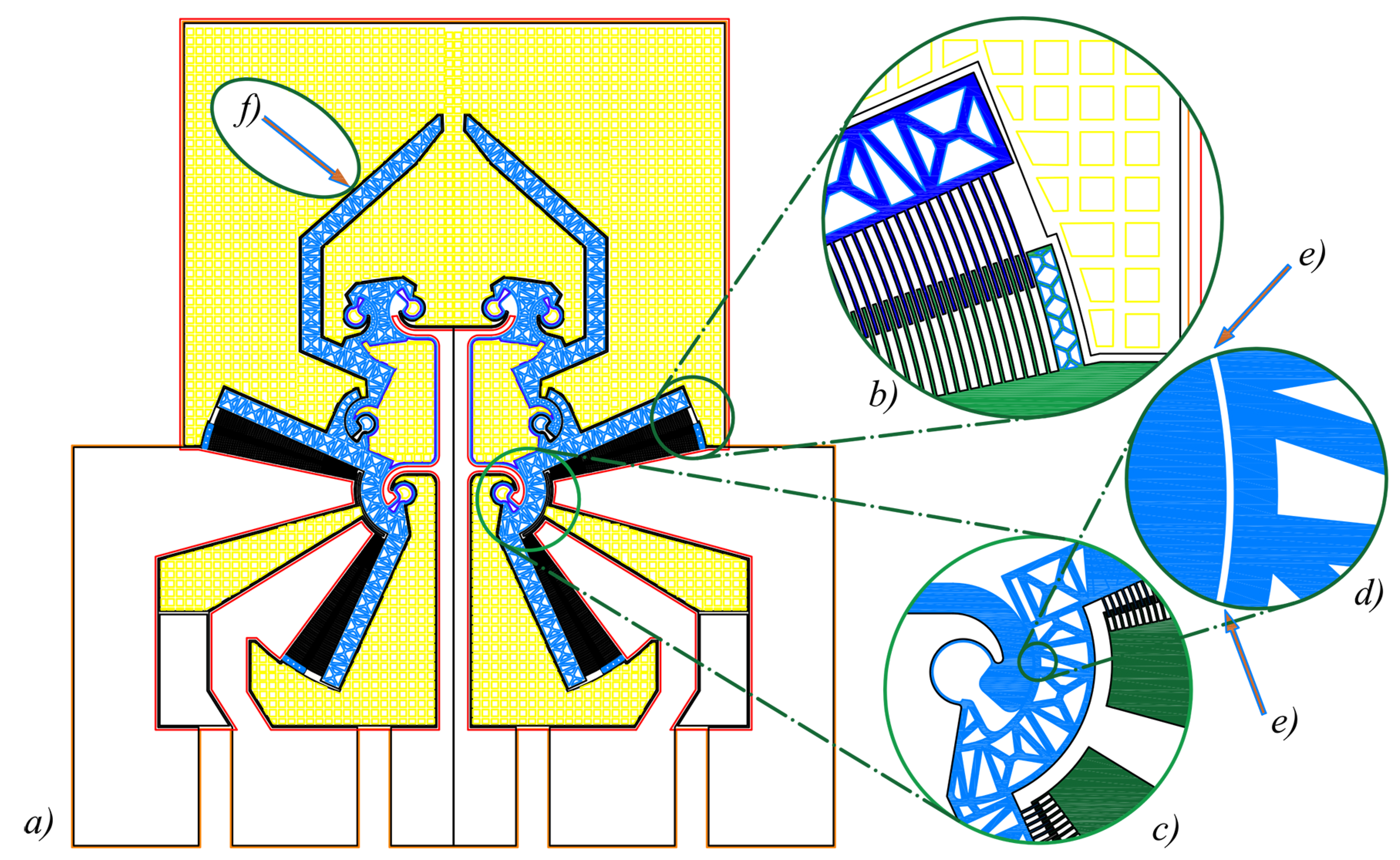
The MEMS consists of a bulk structure which gains mobility thanks to elasticity [43]. Generally, compliant mechanisms can be categorized into two main classes: with lumped or distributed compliance. The CSFHs are particularly suitable to be used as elements of compliant mechanisms with lumped compliance. This opportunity gives rise to new design methods which make use of a topological approach [44,45], such as for example, the rigid-body replacement method [46,47]. By following this approach, starting from a classic four-bar linkage, the mask represented in Figure 1a has been created in a configuration that maximizes the comb drives’ rotations (see the comb drive detailed view presented in Figure 1b) in both closure and opening directions. Then, one CSFH replaces each rotational joint, as illustrated in the detailed view of Figure 1c. Figure 1d shows the gap Figure 1e between the conjugate surfaces in a non contact configuration.
Once each one of the four ordinary revolute pairs has been replaced by a CSFH, a fully compliant four-bar linkage is created (lumped elasticity). Of course, two compliant four-bar mechanisms are needed to assure the grasping operation and, therefore, two four-bar mechanisms are symmetrically positioned to allow the gripping jaws to symmetrically approach the micro object. With reference to Figure 1, the design illustrated by means of the mask Figure 1a has been laid out in such a way that a gripping jaw is attached to the coupler link. For example, the left jaw is pointed out in Figure 1f. The four-bar mechanism provides the jaw tip a wide range of motion from the open to the close extreme configurations.
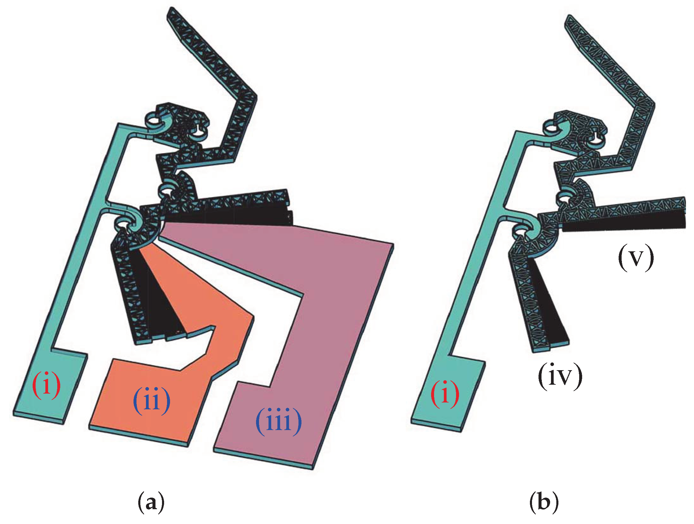
The device is operated by means of two bidirectional electrostatic actuators. The open position of the jaws is obtained by applying a voltage between the pads (i) and (ii) represented in Figure 2a. With reference to the Figure 2b, the mobile set of fingers (iv) rotates counterclockwise, while the coupler link rotates clockwise because of the given configuration of the four-bar linkage. By applying a voltage between pads (i) and (iii) of Figure 2a, the opposite applies, and the comb drive mobile wing (v) rotates clockwise, inducing a counterclockwise rotation of the coupler.
3. Fabrication
The fabrication stage has been performed starting from a 6-inch SEMI standard [48] silicon on insulator (SOI) wafer. Boron has been used as dopant for the wafer SOI device layer, with a resultant resistivity equal to 2–4 Ω·cm. Each wafer has a 500-m handle layer that works as the device support. A 40 m thick silicon layer works as device layer and is bonded at the top of the wafer. The device (top) layer is the most important one because the suspended moving subparts are therein patterned. Between the support and the top layer, a 2-m oxide layer stops etching during silicon patterning. This layer is also necessary to support the top layer before the release of the devices. The support and top layers of the wafer need to be both patterned and so Bosch deep reaction-ion etching (DRIE) process is applied to etch silicon down to the buried oxide layer. The DRIE was performed with an Alcatel AMS200 ICP plasma etcher (Alcatel-Lucent, Paris, France), using a standard two-step bosh recipe with fluorine chemistry. The initial step consists in the deposition of a multilayer mask to provide masking for DRIE etching process on both sides. A 150 nm silicon dioxide is firstly deposited. Then a 200 nm aluminum film is sputtered. A 100 nm film titanium is finally sputtered and standard photolithography is used to pattern this layer stack. The front side is exposed by means of an i-line stepper, while the backside is aligned by means of a broadband mask aligner. Finally, stack etching takes place in IC standard plasma reactors.
After masks patterning, an Alcatel SMS200 (Alcatel-Lucent, Paris, France), etcher is used to etch silicon through DRIE Bosch process. Front and backside etching deepness is equal to 40 m and 500 m, respectively.
At the end of this process, the front and back geometry is transferred on the wafer sides. Therefore, the silicon dioxide intermediate layer must be removed by wet etching in hydrofluoric acid based solution. This treatment allows the device to be released and freely move. During wet etching, residual DRIE mask layers are etched as well.
For the sake of electrostatic actuation, some electrical connections are developed by using the physical vapor deposition of an aluminum layer on the front side.
Aluminum hard mask allows the process to greatly reduce the mask layer thickness. This simplifies sub-micron features patterning, eliminating the obstacle of high aspect ratio thick mask etching. Further, aluminum grants an excellent feature size control during pattern transfer from the mask to silicon, as it eliminates mask edge erosion. The three layer structure and the whole fabrication process have been fully described by Bagolini et al. [20]. In the micro-gripper device, an aspect ratio up to 20 is implemented, but the fabrication module is developed for higher aspect ratio which is not part of present work.
4. Contact and Mobility Tests
As mentioned in Section 2, the adopted mechanism is composed of two symmetric four-bar linkages, each one having four CSFH compliant hinges. Since each of the two mobile suspended structures is held in place by only two 20 × 5 m cross sectional areas, some concern has arisen about the microsystem capability to bear externally applied loads. Hence, the purpose of the present paper consists in testing the mechanical structure of the developed microgripper. For this reason, the experimental activities have been arranged in such a way to provide information on the resistance of the structure, whereas its operational capability in unloaded conditions have been previously investigated [28,49].
In the present paper, a contact force has been externally applied to the right arm of the microgripper. This external load is much more invasive than the torque which is exerted by the electrostatic actuation on the crank-link, because it transmits to the block of mobile fingers not only a moment, but also a force. Such force has generally a radial component, the latter being much dangerous for the microsystem, because it pushes mobile fingers against the fixed ones.
The microgripper under analysis has been tested by means of an Agilent probestation equipped with binocular microscope and needle probes with tri-axial micrometer positioning control. The kinematic functionality of the device has been verified by monitoring the microgripper response to a force exerted by a probe through the contact area.
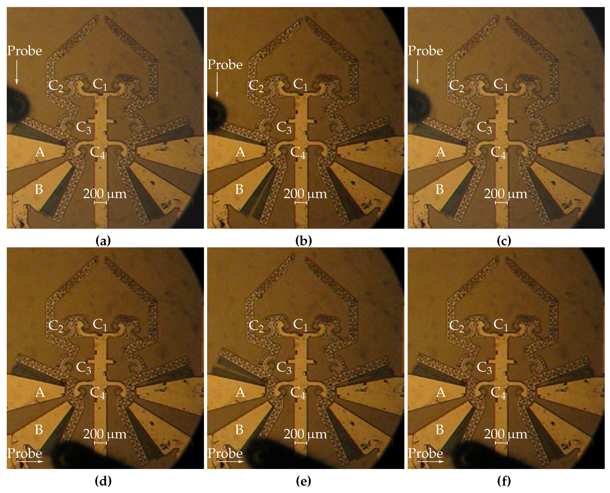
A series of mechanical tests have been conducted by using the three-axis micro probe (Suss PH 150 probehead). As reported in Figure 3, the probe was moved in such a way to mimic the electrostatic action exerted by the comb-drive, rotating the floating part toward the corresponding anchor.
The test is performed considering the following steps:
- (a)
- the probe is positioned in proximity of the closing comb-drive: before contact, the compliant mechanism stands in neutral configuration;
- (b)
- the probe contacts the device and gently pushes the floating part until the maximum rotation is reached. Therefore, the gripper jaw follows a closing trajectory until the device achieve the close configuration (Figure 3b). During this stage, while the rotation angle between floating and anchored parts of the closing comb-drive decreases, the relative rotation between the same parts of the opening comb-drive increases;
- (c)
- the probe is brought back to the initial position; in this phase, the comb-drive is gradually released and the gripper jaw follows an opening trajectory, until the microgripper achieves again its neutral configuration (Figure 3c);
- (d)
- the probe is positioned in proximity of the opening comb-drive: as in the previous case, before contact, the microgripper is in neutral configuration (Figure 3d);
- (e)
- the probe contacts and pushes the floating part to the comb-drive limit position: the gripper jaw follows an opening trajectory until the device achieve the open configuration (Figure 3e). While the rotation between the floating and anchored parts of the opening comb-drive decreases, the relative rotation between the same parts of the closing comb-drive increases (Figure 3e);
- (f)
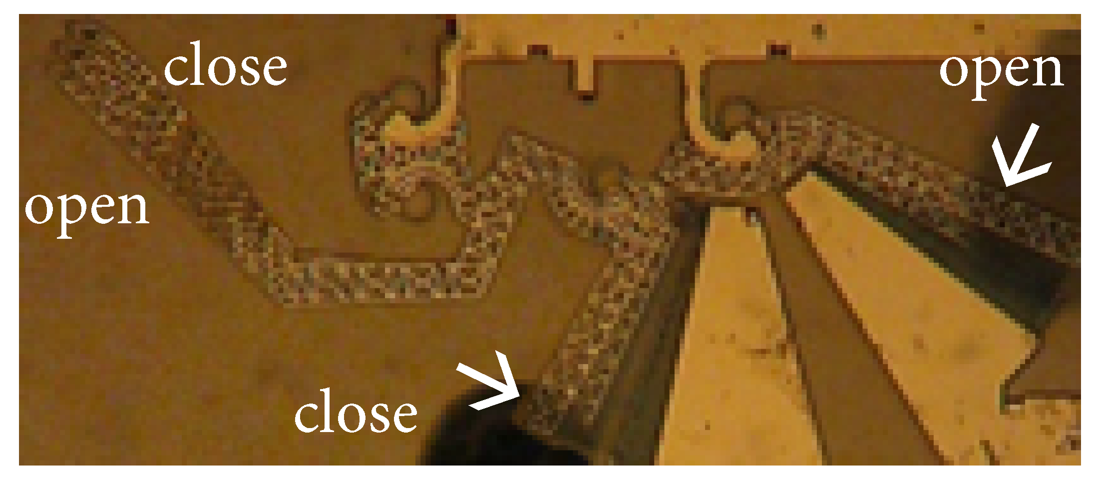
Figure 4 shows three overlapping images reporting the left arm of the microgripper in close, neutral, and open configurations. The probe force could not be directly measured, due to the particular adopted experimental set. However, the applied direction could be obtained by recording the tip displacements from the neutral position, while the force magnitude was measured by means of FEA. In fact, a magnitude of the applied force equal to 320 N was calculated as compatible with the observed close and open configurations. Figure 4 presents also a schematic representation of the two forces corresponding to the close and opening maximal configurations.
Contact Analysis on the Conjugate Surfaces
The CSFH is able to modify substantially the static and dynamic behaviors of the whole microsystem which it belongs to, depending on the occurrence of the contact between the conjugate surfaces. In fact, once the two conjugate surfaces get in touch, a reaction force arises between them. Actually, the purpose of CSFH hinges is to use this reaction force in order to restrict the displacements of the centers of the relative rotations between adjacent links within the size of the gap between the conjugate surface (actually about 5 m). This makes the microsystem quite stable. However, contacts within a CSFH hinge could be activated too late, namely, after the breaking of the curved beam, which represent the elastic part of the CSFH. Therefore, experimental tests of the system response to externally applied forces are fundamental to validate the FEA model and the structural design of the whole system. The conditions under which this contact occurs are useful to optimize the final layout.
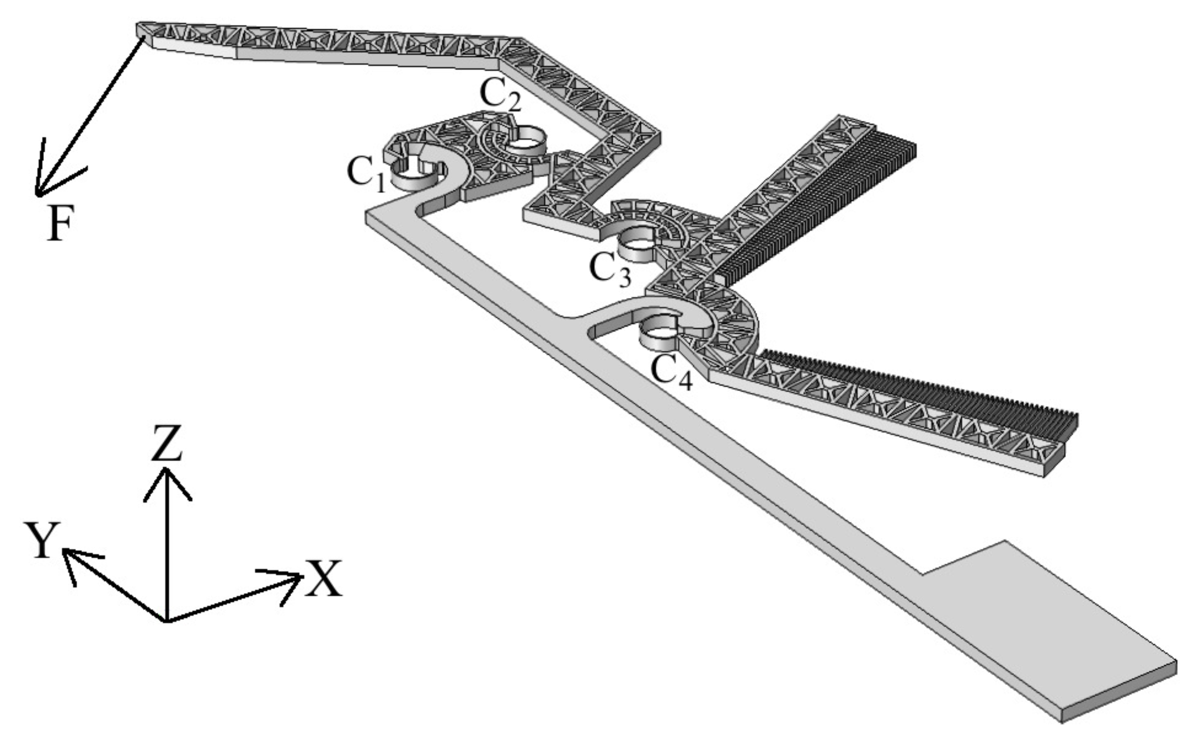
In order to analyze different contact conditions, a force , illustrated in Figure 5, is introduced to represent the action that could be applied to the tip during the gripping task or the positioning phase. The right hand side four-bar linkage is also illustrated together with the CSFH’s , , and . The force magnitude and orientation have been adopted as variable parameters, with the purpose of detecting their critical values in correspondence of which the conjugate profiles of the four embedded CSFH get in touch.
Six different values of the magnitude have been applied, with the assumption that acts on the device working plane, with . The force direction is identified in the plane by means of the angle between and the x axis. The full span from and has been investigated for . It is clear, from the figure, that induces deformations that are concentrated specially on the curved beams, which form the elastic part of the CSFHs. These flexure elements deflect under the action of the internal loads and therefore the conjugate surfaces may get in contact.
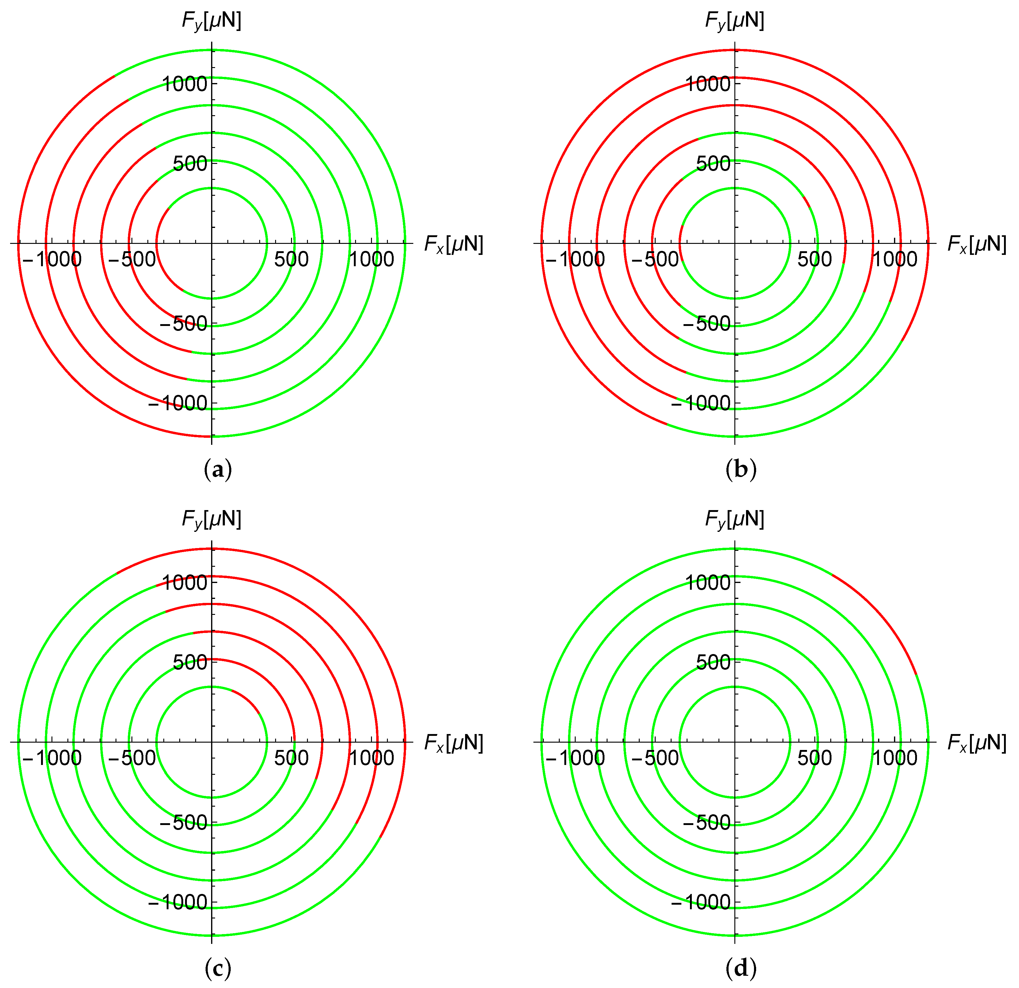
A contact chart has been obtained for each CSFH , as represented in Figure 6, by iterating FEA for discrete number of values of the angle and six values of the force magnitude. Each chart allows designer to immediately understand which are the CSFHs which present contact for the given pair of parameters. For example, contact occurrence in is highlighted by red colored arches and the red sectors are those corresponding to the directions and magnitudes of which induce contact in hinge.
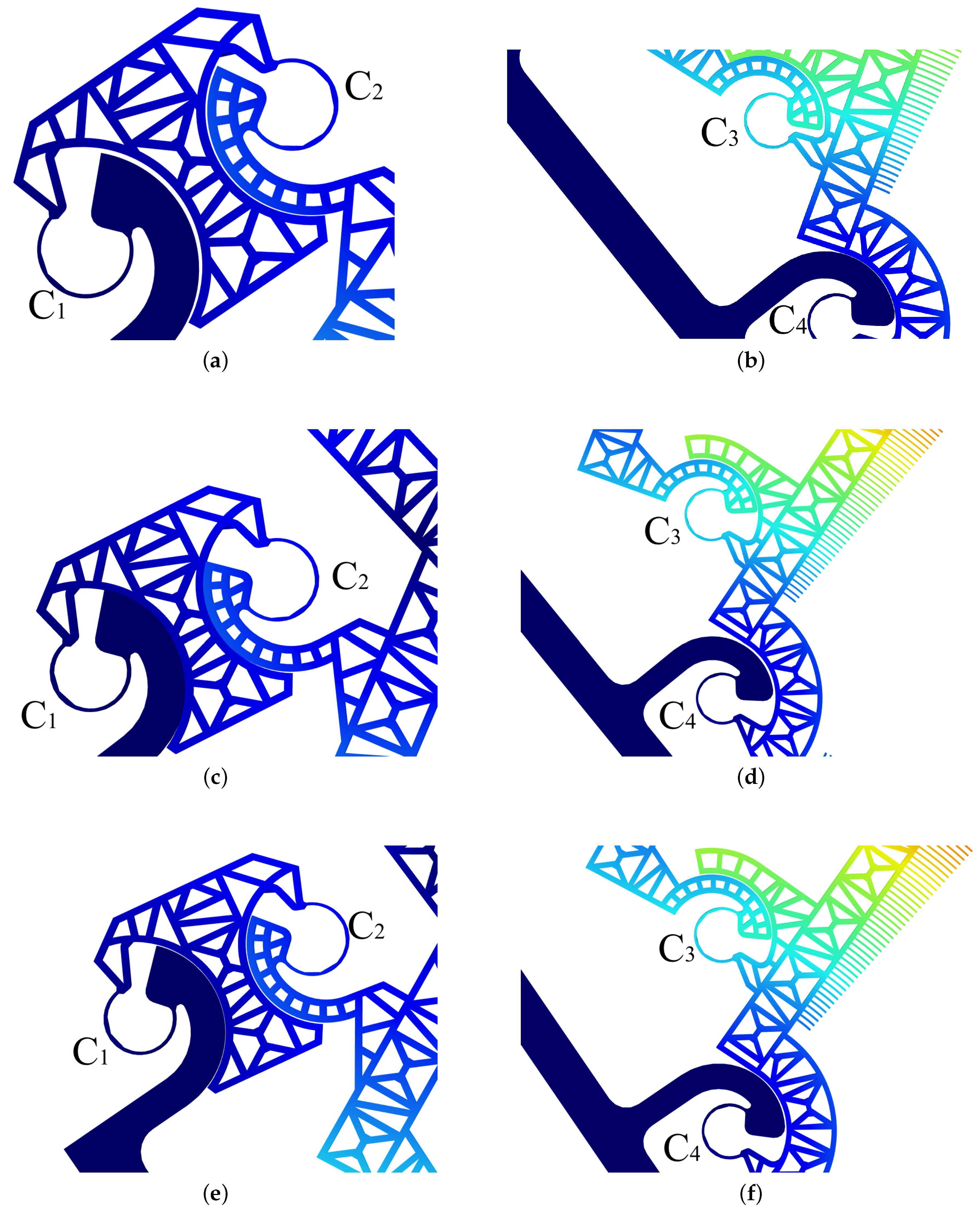
It is possible to observe that there are different conjugate surfaces of the CSFHs into contact for different angles. and are the CSFHs where the conjugate profiles more or less easily get in contact, respectively. Figure 7 shows, in particular, the various CSFHs configurations for different angles . The magnitude of the adopted force (some hundreds of N) is comparable to the value of the forces applied to the comb drive mobile finger set (320 N, as depicted in Figure 4) to fully close or open the configuration.
5. Vibrational Mode Analysis
The versatility of the CSFH makes them useful in many applications such as micro mechanics, biology, etc. However, in many of these fields the analysis of the vibrations is essential on both negative and positive effects. In fact, the induced vibrations can lead to significant positioning errors [50,51] or undesirable contacts between the fingers. Likewise, jaws vibrations can be exploited to release micro objects [52] or to analyse the mechanical characteristics of the soft biological tissues to study possible pathologies [53].
Direct experimental acquisition of the vibrational modes is not easy for MEMS, although there are some successful cases. For example, in-plane low-frequency vibration was measured by means of circular grating Talbot interferometer [54]. With this method vibration from 1 to 25 Hz has been monitored in a plate system. Scanning laser Doppler vibrometry and experimental modal analysis have been also successfully applied to a pair of micro-cantilevers [55]. A charge-coupled device camera and synchronized pulsating illumination has been also used to measure sub-micrometer in-plane dynamics of MEMS devices with nanoscale precision [56]. Another interesting case of optical detection consists in the acquisition of the electromechanical response of a MEMS-technology based micro-mirror used in scanning pico-projectors [57].
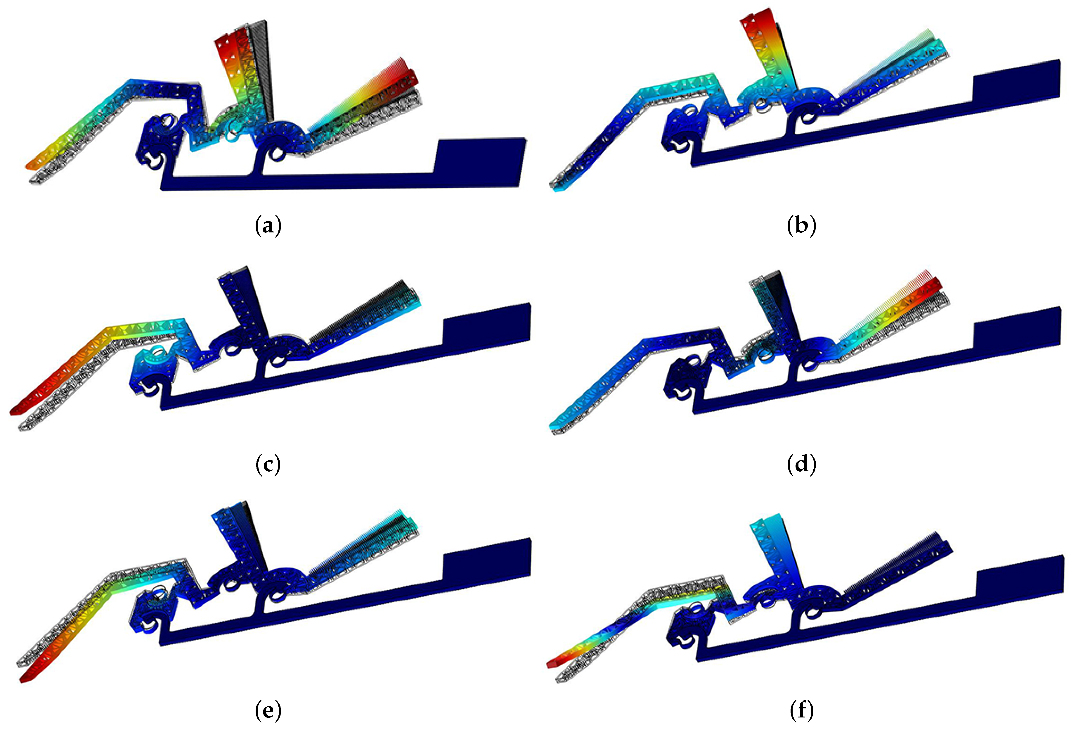
In this paper, the experimental activities have been restricted to the static force analysis only and therefore the vibrational modes have been conveniently obtained via Finite Element Analysis. The modal analysis has been performed with the ANSYS (Canonsburg, PA, USA) software [58]. The first six, eigenmodes and eigenfrequencies have been reported in Figure 8. In this analysis the device anchor has been considered fixed.
The relative displacements between the anchored and the rotating fingers are tolerable only if they correspond to a relative rotation where the center is coincident with the center of the conjugate profiles. Therefore, it is very important to understand the nature of the relative motion for all the possible vibration modes. In particular, the first, second and fourth modes present radial displacements for the fingers and therefore finger contact appears to be theoretically possible.
6. Results and Discussions
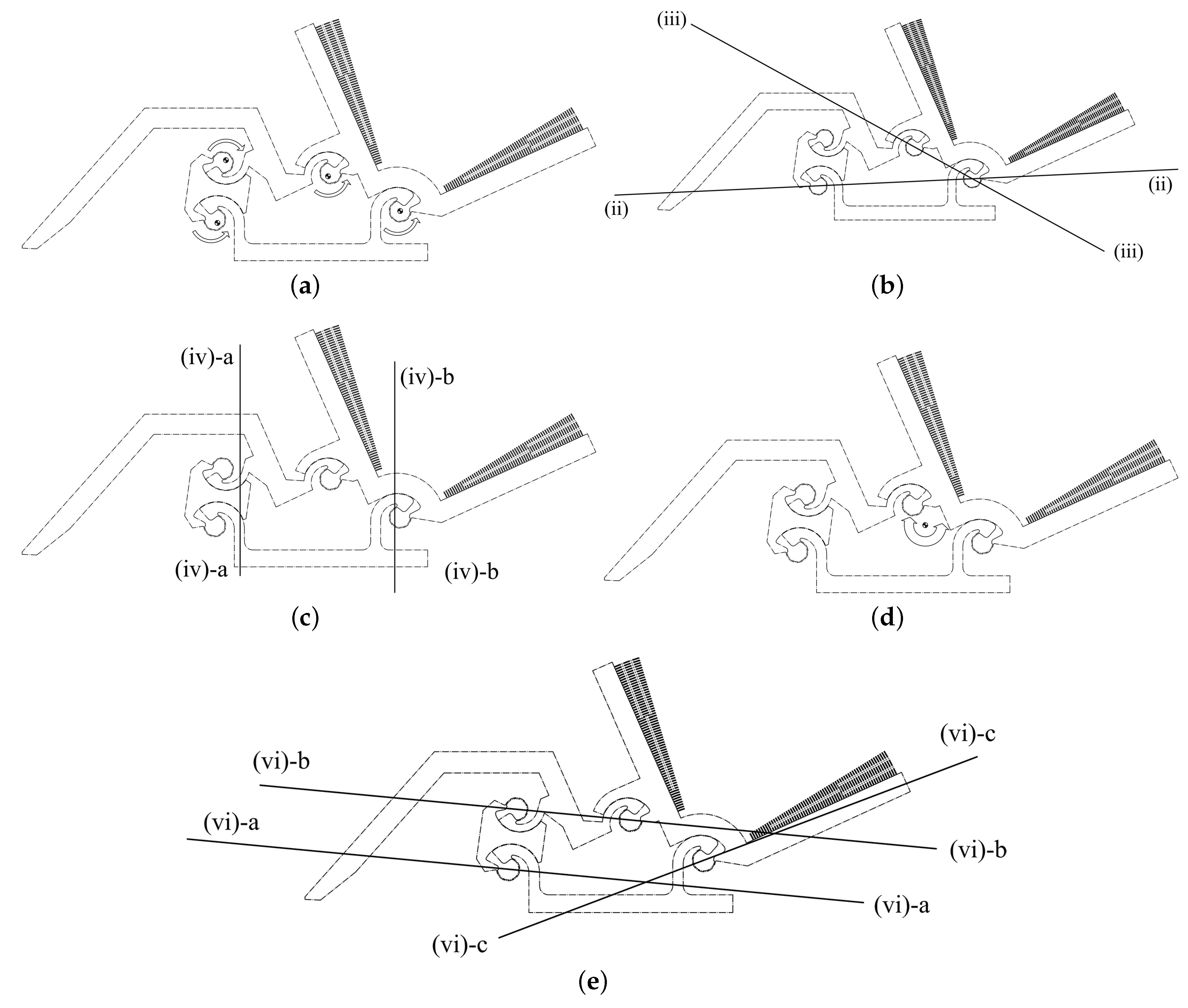
The results obtained by means of FEA can be displayed, for each vibrational mode, as animated sequences of intermediate deformed configurations. This opportunity has been taken to identify, for each mode, those elements with the minimum displacements during the vibration motion, when a certain mode is excited. Considering also the numerical data, these elements can be easily identified for the first 6 modes and the behavior of the structure can be physically interpreted by introducing nodal oscillation axes.
When the system is excited at the first mode (i), three subparts of the structures behave as pseudo-rigid bodies that correspond to the two rockers and the coupler links. Motion is provided by the four flexure hinges and therefore a relative rotation axis appears for each hinge. During this motion all the subparts move within the mask plane and so the structure is characterized by an in-plane motion. The relative rotation axes are orthogonal to the plane and their intersections with the plane are represented in Figure 9a. Hence, first natural mode consists of a motion that is coincident with the motion for which the system has been designed. As a consequence, this kind of deformation is compatible with the geometry of the fingers because the relative rotation axes are practically coincident with the CSFH rotation axes.
The structure oscillations related to the second mode (ii) reveal that the whole structure behaves approximately as if it was a whole plate which rotates around the axis passing through the centers of the framed CSFH, as depicted in Figure 9b. This axis belongs to the main plane and therefore the oscillation will take place out of the plane. However, the mobile fingers are completely positioned by one side of the axis and so their motion goes along a direction which is orthogonal to the gap between the fingers. This means that finger contact remains quite unlikely.
Considering the third mode (iii), a nodal axis through the centers of two adjacent hinges has been identified and illustrated, as the axis (iii), in Figure 9b. In case the system is excited with the third mode, it will behave, approximately, as it was composed by a flexible plate that oscillates around the axis (iii) with additional deformations due to the presence of the anchored parts. Once again, axis (iii) belongs to the main plane and therefore the fingers will be affected also by an out-plane motion, with limited effect on reciprocal contact likelihood.
Taking into account the fourth mode (iv), the modal analysis shows that the microgripper inflects around two the parallel axes (iv)-a and (iv)-b depicted in Figure 9c. These axes belong to the plane and so the displacements will be out-planar directed. The system is roughly comparable to a flexible plate oscillating around nodal axes (iv)-a and (iv)-b, with three different zones. For example, while the central zone is up, the lateral parts will be down, and vice versa.
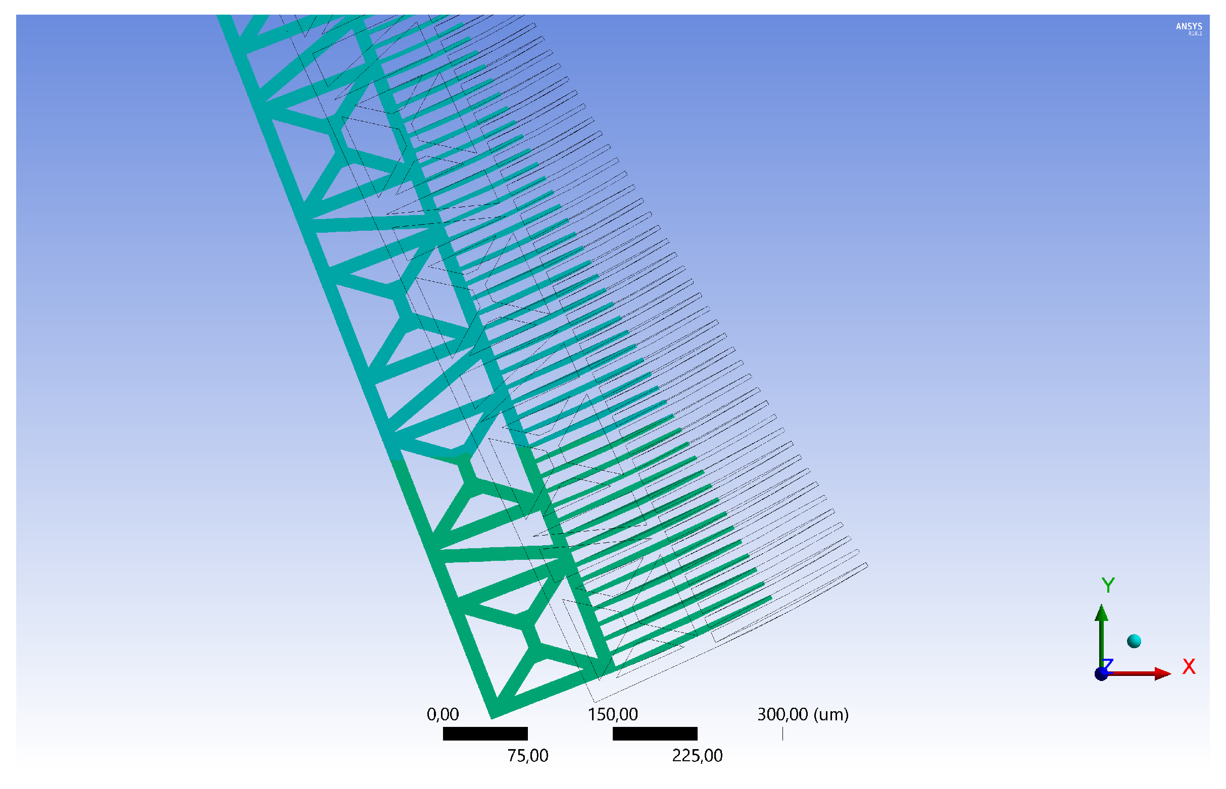
In view of preventing comb drives from finger contact, the fifth node of vibration presents the most difficult circumstance under which the microgripper behaves, approximately, as a pseudo-rigid plate which rotates around a point that is positioned within the internal area of the four-bar linkage, as reported in Figure 9d. This is possible because the CSFHs behave as suspension springs. Unfortunately, this motion is rather dangerous for the comb drive fingers, because the mobile finger sets do not rotate about the CSFH centers. This means that the curved fingers follow no more the natural span of the fixed gaps and so they collide with the fixed sets of fingers. This circumstance is depicted in Figure 10 which shows that the mobile finger set has a radial component of the displacement, having lost the original rotation center, with ineluctable mechanical interference.
The vibrational shape related to the sixth mode is rather complicated to be described. In fact, three nodal axes can be identified (Figure 9e). These axes are all in the fabrication plane. For this case, the microgripper behaves as a flexible plate which inflects around the nodal lines. Since the axes are in the plane, out-plane displacements are the most significant and so no great problem is expected for the fingers.
Considering that the amplitude of the dumped response to external excitation generally have higher values at the lowest frequencies (see for example Reference [59]), the first six modes only have been considered. Furthermore, given the obtained values of the first six natural frequencies, listed in Table 1, the fifth and the sixth modes will have limited influence with respect to the previous four, because their values is more than twice the fourth frequency. Since fingers contact is expected only at the fifth critical mode, its occurrence likelihood is rather limited.
7. Conclusions
The present investigation has shown that the microgripper under analysis it is able to sustain large modifications of the configuration toward both the opening and the closing positions. Considering the size of the embedded flexure hinges, which consist of silicon curved beams with a m cross sectional area, an evident structural robustness has been experimentally observed. In fact, the microgripper has been able to resist to all the actions exerted by the probe. The second part of the investigation has been based on a numerical approach. Firstly, some design charts have been obtained to optimize the likelihood of the contact between the conjugate profiles. Secondly, FEA has been used to detect the main vibrational modes, whose analysis is necessary to prevent fingers contacts. The whole investigation has therefore confirmed that the microgripper under analysis is robust in operational conditions and promising for the applications.
Author Contributions
Conceptualization, all the authors; Methodology, F.B. and M.V.; Software, F.B.; Validation, all the authors; Formal analysis, F.B. and M.V.; Investigation and resources for fabrication, A.B. and P.B.; Data Curation, all the authors; Writing—original draft preparation, Writing—review & Editing & Visualization, M.V. and N.P.B.; Supervision, P.B. and N.P.B.
Funding
This research received no external funding.
Conflicts of Interest
The authors declare no conflict of interest.
References
- Lobontiu, N.; Garcia, E.; Canfield, S. Torsional stiffness of several variable rectangular cross-section flexure hinges for macro-scale and MEMS applications. Smart Mater. Struct. 2004, 13, 12–19. [Google Scholar] [CrossRef]
- Gad-el Hak, M.E. (Ed.) The MEMS Handbook, 2nd ed.; Mechanical and Aerospace Engineering Series, 3 Volume Set; CRC Press: Boca Raton, FL, USA, 2005. [Google Scholar]
- Bhushan, B.E. (Ed.) Springer Handbook of Nanotechnology; Springer Handbooks; Springer: Berlin, Germany, 2017. [Google Scholar]
- Dochshanov, A.; Verotti, M.; Belfiore, N.P. A Comprehensive Survey on Microgrippers Design: Operational Strategy. J. Mech. Des. Trans. ASME 2017, 139, 070801. [Google Scholar] [CrossRef]
- Verotti, M.; Dochshanov, A.; Belfiore, N.P. A Comprehensive Survey on Microgrippers Design: Mechanical Structure. J. Mech. Des. Trans. ASME 2017, 139, 060801. [Google Scholar] [CrossRef]
- Cecil, J.; Powell, D.; Vasquez, D. Assembly and manipulation of micro devices—A state of the art survey. Robot. Comput.-Integr. Manuf. 2007, 23, 580–588. [Google Scholar] [CrossRef]
- Zhang, J.; Lu, K.; Chen, W.; Jiang, J.; Chen, W. Monolithically integrated two-axis microgripper for polarization maintaining in optical fiber assembly. Rev. Sci. Instrum. 2015, 86, 025105. [Google Scholar] [CrossRef] [PubMed]
- Chen, W.; Shi, X.; Chen, W.; Zhang, J. A two degree of freedom micro-gripper with grasping and rotating functions for optical fibers assembling. Rev. Sci. Instrum. 2013, 84, 115111. [Google Scholar] [CrossRef] [PubMed]
- Ingber, D.E. Cellular mechanotransduction: Putting all the pieces together again. FASEB J. 2006, 20, 811–827. [Google Scholar] [CrossRef] [PubMed]
- Moeendarbary, E.; Harris, A.R. Cell mechanics: Principles, practices, and prospects. Wiley Interdiscip. Rev. 2014, 6, 371–388. [Google Scholar] [CrossRef]
- Beyeler, F.; Neild, A.; Oberti, S.; Bell, D.J.; Sun, Y.; Dual, J.; Nelson, B.J. Monolithically fabricated microgripper with integrated force sensor for manipulating microobjects and biological cells aligned in an ultrasonic field. J. Microelectromech. Syst. 2007, 16, 7–15. [Google Scholar] [CrossRef]
- Kim, K.; Liu, X.; Zhang, Y.; Sun, Y. Nanonewton force-controlled manipulation of biological cells using a monolithic MEMS microgripper with two-axis force feedback. J. Micromech. Microeng. 2008, 18, 055013. [Google Scholar] [CrossRef]
- Di Giamberardino, P.; Bagolini, A.; Bellutti, P.; Rudas, I.; Verotti, M.; Botta, F.; Belfiore, N.P. New MEMS tweezers for the viscoelastic characterization of soft materials at the microscale. Micromachines 2017, 9, 15. [Google Scholar] [CrossRef] [PubMed]
- Di Giamberardino, P.; Aceto, M.; Giannini, O.; Verotti, M. Recursive Least Squares Filtering Algorithms for On-Line Viscoelastic Characterization of Biosamples. Actuators 2018, 7, 74. [Google Scholar] [CrossRef]
- Lan, C.C.; Lin, C.M.; Fan, C.H. A self-sensing microgripper module with wide handling ranges. IEEE/ASME Trans. Mechatron. 2011, 16, 141–150. [Google Scholar] [CrossRef]
- Shen, Y.; Winder, E.; Xi, N.; Pomeroy, C.; Wejinya, U. Closed-loop optimal control-enabled piezoelectric microforce sensors. IEEE/ASME Trans. Mechatron. 2006, 11, 420–427. [Google Scholar] [CrossRef] [Green Version]
- Lu, Z.; Chen, P.; Ganapathy, A.; Zhao, G.; Nam, J.; Yang, G.; Burdet, E.; Teo, C.; Meng, Q.; Lin, W. A force-feedback control system for micro-assembly. J. Micromech. Microeng. 2006, 16, 1861–1868. [Google Scholar] [CrossRef]
- Rakotondrabe, M.; Rabenorosoa, K.; Agnus, J.; Chaillet, N. Robust feedforward-feedback control of a nonlinear and oscillating 2-DoF piezocantilever. IEEE Trans. Autom. Sci. Eng. 2011, 8, 506–519. [Google Scholar] [CrossRef] [Green Version]
- Belfiore, N.P.; Broggiato, G.B.; Verotti, M.; Balucani, M.; Crescenzi, R.; Bagolini, A.; Bellutti, P.; Boscardin, M. Simulation and construction of a mems CSFH based microgripper. Int. J. Mech. Control 2015, 16, 21–30. [Google Scholar]
- Bagolini, A.; Ronchin, S.; Bellutti, P.; Chistè, M.; Verotti, M.; Belfiore, N.P. Fabrication of Novel MEMS Microgrippers by Deep Reactive Ion Etching With Metal Hard Mask. J. Microelectromech. Syst. 2017, 26, 926–934. [Google Scholar] [CrossRef]
- Belfiore, N.P.; Scaccia, M.; Ianniello, F.; Presta, M. Selective Compliance Hinge. U.S. Patent 8,191,204 B2, 5 June 2012. [Google Scholar]
- Belfiore, N.; Simeone, P. Inverse kinetostatic analysis of compliant four-bar linkages. Mech. Mach. Theory 2013, 69, 350–372. [Google Scholar] [CrossRef]
- Nenzi, P.; Crescenzi, R.; Dolgyi, A.; Klyshko, A.; Bondarenko, V.; Belfiore, N.; Balucani, M. High density compliant contacting technology for integrated high power modules in automotive applications. In Proceedings of the Electronic Components and Technology Conference, San Diego, CA, USA, 29 May–1 June 2012; pp. 1976–1983. [Google Scholar]
- Balucani, M.; Belfiore, N.; Crescenzi, R.; Genua, M.; Verotti, M. Developing and modeling a plane 3 DOF compliant micromanipulator by means of a dedicated MBS code. In Proceedings of the 2011 NSTI Nanotechnology Conference and Expo (NSTI-Nanotech 2011), Boston, MA, USA, 13–16 June 2011; Volume 2, pp. 659–662. [Google Scholar]
- Balucani, M.; Belfiore, N.; Crescenzi, R.; Verotti, M. The development of a MEMS/NEMS-based 3 D.O.F. compliant micro robot. Int. J. Mech. Control 2011, 12, 3–10. [Google Scholar]
- Belfiore, N.; Balucani, M.; Crescenzi, R.; Verotti, M. Performance analysis of compliant MEMS parallel robots through pseudo-rigid-body model synthesis. In Proceedings of the ASME 2012 11th Biennial Conference on Engineering Systems Design and Analysis (ESDA 2012), Nantes, France, 2–4 July 2012; Volume 3, pp. 329–334. [Google Scholar]
- Belfiore, N.P.; Prosperi, G.; Crescenzi, R. A simple application of conjugate profile theory to the development of a silicon micro tribometer. In Proceedings of the ASME 2014 12th Biennial Conference on Engineering Systems Design and Analysis (ESDA 2014), Copenhagen, Denmark, 25–27 July 2014; Web Portal ASME (American Society of Mechanical Engineers): New York, NY, USA, 2014; Volume 2. [Google Scholar]
- Crescenzi, R.; Balucani, M.; Belfiore, N.P. Operational characterization of CSFH MEMS technology based hinges. J. Micromech. Microeng. 2018, 28, 055012. [Google Scholar] [CrossRef] [Green Version]
- Zeman, M.J.F.; Bordatchev, E.V.; Knopf, G.K. Design, kinematic modeling and performance testing of an electro-thermally driven microgripper for micromanipulation applications. J. Micromech. Microeng. 2006, 16, 1540. [Google Scholar] [CrossRef]
- Zhang, R.; Chu, J.; Wang, H.; Chen, Z. A multipurpose electrothermal microgripper for biological micro-manipulation. Microsyst. Technol. 2013, 19, 89–97. [Google Scholar] [CrossRef]
- Chang, R.; Wang, H.; Wang, Y. Development of mesoscopic polymer gripper system guided by precision design axioms. Precis. Eng. 2003, 27, 362–369. [Google Scholar] [CrossRef]
- Kohl, M.; Just, E.; Pfleging, W.; Miyazaki, S. SMA microgripper with integrated antagonism. Sens. Actuators A Phys. 2000, 83, 208–213. [Google Scholar] [CrossRef]
- Chen, T.; Chen, L.; Sun, L.; Wang, J.; Li, X. A sidewall piezoresistive force sensor used in a MEMS gripper. In Proceedings of the International Conference on Intelligent Robotics and Applications, Wuhan, China, 15–17 October 2008; Springer: Berlin, Germany, 2008; pp. 207–216. [Google Scholar]
- Zubir, M.N.M.; Shirinzadeh, B.; Tian, Y. Development of a novel flexure-based microgripper for high precision micro-object manipulation. Sens. Actuators A Phys. 2009, 150, 257–266. [Google Scholar] [CrossRef]
- Dong, J.; Ferreira, P.M. Electrostatically actuated cantilever with SOI-MEMS parallel kinematic XY stage. J. Microelectromech. Syst. 2009, 18, 641–651. [Google Scholar] [CrossRef]
- Selvakumar, A.; Najafi, K. Vertical comb array microactuators. J. Microelectromech. Syst. 2003, 12, 440–449. [Google Scholar] [CrossRef]
- Xie, H.; Fedder, G.K. Vertical comb-finger capacitive actuation and sensing for CMOS-MEMS. Sens. Actuators A Phys. 2002, 95, 212–221. [Google Scholar] [CrossRef]
- Chen, T.; Sun, L.; Chen, L.; Rong, W.; Li, X. A hybrid-type electrostatically driven microgripper with an integrated vacuum tool. Sens. Actuators A Phys. 2010, 158, 320–327. [Google Scholar] [CrossRef]
- Wierzbicki, R.; Houston, K.; Heerlein, H.; Barth, W.; Debski, T.; Eisinberg, A.; Menciassi, A.; Carrozza, M.; Dario, P. Design and fabrication of an electrostatically driven microgripper for blood vessel manipulation. Microelectron. Eng. 2006, 83, 1651–1654. [Google Scholar] [CrossRef]
- Hou, M.T.K.; Huang, J.Y.; Jiang, S.S.; Yeh, J.A. In-plane rotary comb-drive actuator for a variable optical attenuator. J. Micro/Nanolithogr. MEMS MOEMS 2008, 7, 043015. [Google Scholar]
- Yeh, J.; Jiang, S.S.; Lee, C. MOEMS variable optical attenuators using rotary comb drive actuators. IEEE Photonics Technol. Lett. 2006, 18, 1170–1172. [Google Scholar] [CrossRef]
- Cecchi, R.; Verotti, M.; Capata, R.; Dochshanov, A.; Broggiato, G.; Crescenzi, R.; Balucani, M.; Natali, S.; Razzano, G.; Lucchese, F.; et al. Development of micro-grippers for tissue and cell manipulation with direct morphological comparison. Micromachines 2015, 6, 1710–1728. [Google Scholar] [CrossRef]
- Howell, L.L. Compliant Mechanisms. In Encyclopedia of Nanotechnology; Bhushan, B., Ed.; Springer: Dordrecht, The Netherlands, 2016; pp. 604–611. [Google Scholar]
- Belfiore, N.P. Distributed Databases for the development of Mechanisms Topology. Mech. Mach. Theory 2000, 35, 1727–1744. [Google Scholar] [CrossRef]
- Belfiore, N.P. Brief note on the concept of planarity for kinematic chains. Mech. Mach. Theory 2000, 35, 1745–1750. [Google Scholar] [CrossRef]
- Sanò, P.; Verotti, M.; Bosetti, P.; Belfiore, N.P. Kinematic Synthesis of a D-Drive MEMS Device with Rigid-Body Replacement Method. J. Mech. Des. Trans. ASME 2018, 140, 075001. [Google Scholar] [CrossRef]
- Verotti, M.; Dochshanov, A.; Belfiore, N.P. Compliance Synthesis of CSFH MEMS-Based Microgrippers. J. Mech. Des. Trans. ASME 2017, 139, 022301. [Google Scholar] [CrossRef]
- SEMICON West. Beyond Smart. Available online: www.semifoundation.org (accessed on 9 October 2018).
- Potrich, C.; Lunelli, L.; Bagolini, A.; Bellutti, P.; Pederzolli, C.; Verotti, M.; Belfiore, N.P. Innovative silicon microgrippers for biomedical applications: Design, mechanical simulation and evaluation of protein fouling. Actuators 2018, 7, 12. [Google Scholar] [CrossRef]
- Demaghsi, H.; Mirzajani, H.; Ghavifekr, H.B. A novel electrostatic based microgripper (cellgripper) integrated with contact sensor and equipped with vibrating system to release particles actively. Microsyst. Technol. 2014, 20, 2191–2202. [Google Scholar] [CrossRef]
- Park, J.; Moon, W. The systematic design and fabrication of a three-chopstick microgripper. Int. J. Adv. Manuf. Technol. 2005, 26, 251–261. [Google Scholar] [CrossRef]
- Fang, Y.; Tan, X. A dynamic JKR model with application to vibrational release in micromanipulation. In Proceedings of the 2006 IEEE/RSJ International Conference on Intelligent Robots and Systems, Beijing, China, 9–15 October 2006; pp. 1341–1346. [Google Scholar]
- Valtorta, D.; Mazza, E. Dynamic measurement of soft tissue viscoelastic properties with a torsional resonator device. Med. Image Anal. 2005, 9, 481–490. [Google Scholar] [CrossRef] [PubMed]
- Agarwal, S.; Shakher, C. Low-frequency in-plane vibration monitoring/measurement using circular grating Talbot interferometer. Opt. Eng. 2018, 57, 054112. [Google Scholar] [CrossRef]
- Rothberg, S.J.; Allen, M.S.; Castellini, P.; Di Maio, D.; Dirckx, J.J.J.; Ewins, D.J.; Halkon, B.J.; Muyshondt, P.; Paone, N.; Ryan, T.; et al. An international review of laser Doppler vibrometry: Making light work of vibration measurement. Opt. Lasers Eng. 2017, 99, 11–22. [Google Scholar] [CrossRef] [Green Version]
- Warnat, S.; Forbrigger, C.; Kujath, M.; Hubbard, T. Nano-scale measurement of sub-micrometer MEMS in-plane dynamics using synchronized illumination. J. Micromech. Microeng. 2015, 25, 095004. [Google Scholar] [CrossRef]
- Silva, G.; Carpignano, F.; Guerinoni, F.; Costantini, S.; De Fazio, M.; Merlo, S. Optical detection of the electromechanical response of MEMS micromirrors designed for scanning picoprojectors. IEEE J. Sel. Top. Quantum Electron. 2015, 21, 147–156. [Google Scholar] [CrossRef]
- ANSYS, Inc., Canonsburg, PA, USA. Available online: https://www.ansys.com (accessed on 9 October 2018).
- Weaver, W.; Timoshenko, S.P.; Young, D.H. Vibration Problems in Engineering; John Wiley and Sons: Hoboken, NJ, USA, 1990. [Google Scholar]
Figure 1.
The mask adopted during Deep Reactive-Ion Etching (DRIE) process (a); details of the fingers of the comb drive (b); the Conjugate Surface Flexure Hinge (CSFH) hinge (c); the gap between the conjugate surfaces (e) and the left-hand side jaw (f).
Figure 1.
The mask adopted during Deep Reactive-Ion Etching (DRIE) process (a); details of the fingers of the comb drive (b); the Conjugate Surface Flexure Hinge (CSFH) hinge (c); the gap between the conjugate surfaces (e) and the left-hand side jaw (f).

Figure 2.
Model of the right jaw of the microgripper with (a) and without (b) the control pads: (i) device anchor; (ii) opening control pad; (iii) closing control pad; (iv) and (v) mobile fingers engaged with (ii) and (iii), respectively.
Figure 2.
Model of the right jaw of the microgripper with (a) and without (b) the control pads: (i) device anchor; (ii) opening control pad; (iii) closing control pad; (iv) and (v) mobile fingers engaged with (ii) and (iii), respectively.

Figure 3.
Steps of the mechanical testing procedure: (a) Probe positioning near the closing comb-drive (A); (b) Close configuration: stroke limit for the closing comb-drive (A); (c) Neutral configuration: releasing of the closing comb-drive (A); (d) Probe positioning near the opening comb-drive (B); (e) Open configuration: stroke limit for the opening comb-drive (B); (f) Neutral configuration: releasing of the opening comb-drive (B).

Figure 4.
Overlapping images of the microgripper in close, neutral, and open configurations.

Figure 5.
Static load to modify the CSFH contact.

Figure 6.
Force vs. contact diagrams: contact charts for the joint (a); (b); (c); and (d), respectively.
Figure 6.
Force vs. contact diagrams: contact charts for the joint (a); (b); (c); and (d), respectively.

Figure 7.
Configurations of CSFHs with (N): (a) and at ; (b) and at ; (c) and at ; (d) and at ; (e) and at ; (f) and at .
Figure 7.
Configurations of CSFHs with (N): (a) and at ; (b) and at ; (c) and at ; (d) and at ; (e) and at ; (f) and at .

Figure 8.
Eigenmodes and eigenfrequencies: first ( kHz) (a); second ( kHz) (b); third ( kHz) (c); fourth ( kHz) (d); fifth ( kHz) (e); and sixth ( kHz) (f) eigenmode, respectively.
Figure 8.
Eigenmodes and eigenfrequencies: first ( kHz) (a); second ( kHz) (b); third ( kHz) (c); fourth ( kHz) (d); fifth ( kHz) (e); and sixth ( kHz) (f) eigenmode, respectively.

Figure 9.
Pseudo-axes of rotation corresponding to the first 6 vibrational modes: (a) In-plane rotation axes for mode (i); (b) Out-plane rotation axes for modes (ii) and (iii); (c) Out-plane rotation axis for mode (iv); (d) In-plane rotation axis for mode (v); (e) Out-plane rotation axis for mode (vi).

Figure 10.
Critical configuration of the comb drive fingers when mode (v) is excited.


Table 1.
Critical modes for comb drives fingers.
| Frequency | kHz | Critical | Plane | Rotation Axes |
|---|---|---|---|---|
| i | 1.51 | no | in | 4 |
| ii | 1.94 | no | out | 1 |
| iii | 2.47 | no | out | 1 |
| iv | 3.00 | no | out | 2 |
| v | 6.41 | yes | in | 1 |
| vi | 6.46 | no | out | 3 |
© 2018 by the authors. Licensee MDPI, Basel, Switzerland. This article is an open access article distributed under the terms and conditions of the Creative Commons Attribution (CC BY) license (http://creativecommons.org/licenses/by/4.0/).
Share and Cite
MDPI and ACS Style
Botta, F.; Verotti, M.; Bagolini, A.; Bellutti, P.; Belfiore, N.P. Mechanical Response of Four-Bar Linkage Microgrippers with Bidirectional Electrostatic Actuation. Actuators 2018, 7, 78. https://doi.org/10.3390/act7040078
AMA Style
Botta F, Verotti M, Bagolini A, Bellutti P, Belfiore NP. Mechanical Response of Four-Bar Linkage Microgrippers with Bidirectional Electrostatic Actuation. Actuators. 2018; 7(4):78. https://doi.org/10.3390/act7040078
Chicago/Turabian StyleBotta, Fabio, Matteo Verotti, Alvise Bagolini, Pierluigi Bellutti, and Nicola Pio Belfiore. 2018. "Mechanical Response of Four-Bar Linkage Microgrippers with Bidirectional Electrostatic Actuation" Actuators 7, no. 4: 78. https://doi.org/10.3390/act7040078
Note that from the first issue of 2016, this journal uses article numbers instead of page numbers. See further details here.