On-Board Pneumatic Pressure Generation Methods for Soft Robotics Applications


Workgroup on System Technologies and Engineering Design Methodology, Hamburg University of Technology, 21073 Hamburg, Germany
*
Author to whom correspondence should be addressed.
Actuators 2019, 8(1), 2; https://doi.org/10.3390/act8010002
Submission received: 14 November 2018
/
Revised: 8 December 2018
/
Accepted: 20 December 2018
/
Published: 23 December 2018
(This article belongs to the Special Issue Actuation for Agile Robots)
Abstract
:The design and construction of a soft robot are challenging tasks on their own. When the robot is supposed to operate without a tether, it becomes even more demanding. While a tethered operation is sufficient for a stationary use, it is impractical for wearable robots or performing tasks that demand a high mobility. Choosing and implementing an on-board pneumatic pressure source are particularly complex tasks. There are several different pressure generation methods to choose from, each with very different properties and ways of implementation. This review paper is written with the intention of informing about all pressure generation methods available in the field of soft robotics and providing an overview of the abilities and properties of each method. Nine different methods are described regarding their working principle, pressure generation behavior, energetic considerations, safety aspects, and suitability for soft robotics applications. All presented methods are evaluated in the most important categories for soft robotics pressure sources and compared to each other qualitatively and quantitatively as far as possible. The aim of the results presented is to simplify the choice of a suitable pressure generation method when designing an on-board pressure source for a soft robot.
1. Introduction
Conventional robots with rigid bodies are commonly used for industrial purposes. They are highly optimized to perform a single task very quickly and efficiently, but the majority of them are of limited use for other purposes due to their lack of adaptability. Additionally, most rigid robots are unsafe for human-robot interaction. Therefore, it is common practice to separate human workers from robotic workspaces.
A more recent approach in the field of robotics led to the development of a new class of robots that are referred to as soft robots [1,2,3,4]. The aim of developing soft robots is to build machines with entirely and continuously deformable bodies and structures that serve the adaptability and safety compared to their conventional rigid-bodied counterparts. Soft robots are mostly made from soft or extensible materials, such as different kinds of rubber, that can deform and as a result, absorb the energy of a possible collision, making them much safer for human-robot interaction. They are often inspired by structures found in nature and can perform many different locomotion tasks, such as walking [5,6], rolling [7], grasping [8], swimming [9,10], and jumping [11,12,13,14]. Soft robots can even be used as wearable devices for medical purposes like rehabilitation [15].
While electric motors are commonly used to achieve motion in rigid-bodied robots, bending or expanding actuators are generally used in soft robots. The deformation of soft actuators can either be realized by using tendons of a variable length, such as tension cables, or by pneumatically inflating channels located inside the soft material [4].
Because pneumatic actuators are a popular choice in soft robotics, pneumatic pressure sources are necessary to drive many soft robots. With most designs, the different segments of a soft robot are individually addressable with the aid of valves from a single source of pressure. Large and heavy compressors or industrial-sized compressed gas tanks were used in the past to realize a tethered operation. While tethered designs are well-suited to stationary use, mobile or wearable soft robots would benefit greatly from sustained untethered operation. If an independently operating soft robot is to be constructed, one of the key challenges is the design and implementation of a soft pneumatic pressure source that is suitable for actuating the pneumatic network.
Especially with small-scale wearable applications in mind, the system of pressure generation should be as compact and lightweight as possible, while providing enough pressure and energy for long-term operation. Though no exact upper size limit exists, this work is focused on soft machines with a weight of up to a few kilograms. The gauge pressure required for powering small pneumatic actuators usually ranges from 50 to 500 kPa [16]. For high power applications, significantly higher pressures can result in a better performance in conjunction with specially designed actuators [13].
There is no perfect on-board pressure generation method that can meet all the desired abilities and requirements without any downsides. As a result, choosing the best suited pressure generation method is a complicated task, with many relevant factors. Ideally, the method of choice is supposed to achieve high and sustained pressures and flow rates that are easily variable. It should store a lot of energy, be safe to use in every regard, operate silently, and be reusable and simple to implement at a low cost. Several different means of providing pressure for an untethered operation have been used, such as mechanical compression [6], storing previously compressed gas [9,10], using phase change [16,17,18], and several different chemical reactions [11,19,20,21,22]. This review paper is written with the intention to simplify the choice of a pressure generation method when a soft robot is to be designed by giving an overview of the available options and their respective abilities and properties.
This paper is organized as follows. The theoretical background required to follow this work is provided in Section 2. In Section 3, the working principles of several selected pressure generation methods are described and analyzed regarding their means of pressure generation, capabilities as energy sources, safety aspects, and suitability for application in soft robotics. All suitable pressure generation methods found during extensive literature research regarding onboard power sources in the field of soft robotics are covered in this work. Afterwards, all methods of pressure generation are evaluated and compared to each other regarding key criteria. At the end of this work, in Section 4, the content and results are summarized and a conclusion is drawn.
2. Theoretical Background
The ideal gas law,
describes the general relation between pressure p, volume V, amount of gaseous substance n, and temperature T of ideal gases. They are connected by the ideal gas constant R = 8.314 J/(mol K). The assumption of an ideal gas is adequate for low pressures and sufficiently high temperatures. The amount of substance of a chemical can be obtained from its mass m and molar mass M:
The volume, the amount of substance, or the temperature can be adjusted independently or in combination to generate pressure for pneumatic use.
Chemical reactions performed inside closed containers that are filled with ideal gas can result in pressure changes for several reasons. In the case of exothermic reactions, energy in the form of heat can be released, while the system absorbs heat from its surroundings during endothermic reactions. It depends on the enthalpy change ∆H of the system whether a chemical reaction is exothermic or endothermic. In an endothermic reaction, the enthalpy change has a positive value (∆H > 0), and it has a negative value (∆H < 0) for exothermic reactions. This process can cause temperature changes that affect the pressure according to the ideal gas law.
In addition to possible temperature changes, chemical reactions can also affect the amount of gaseous substance. As an example, the dissociation of a gas molecule AB into two gas molecules A and B is considered:
This chemical reaction causes the amount of substance to increase, which also increases the pressure at otherwise unchanged conditions.
The rate of reaction r describes the speed of a chemical reaction. For example, the reaction rate of a chemical reaction between the substances C and D with their respective concentrations cC and cD can be calculated as follows:
The exponents m and n are the partial orders of reaction for the substances C and D, and their sum is the order of the entire reaction. The reaction rate constant k is independent of the order of reaction and can be calculated with the Arrhenius equation:
in which k0 is the pre-exponential factor, which is constant for each chemical reaction, and Ea is the activation energy of the reaction. The universal gas constant R and temperature T are already known from the ideal gas law described above.
Chemical reactions cannot only be performed in the gas phase, but also in the liquid phase. Diluted solutions are often used for this purpose. The concentration c of a chemical in relation to its amount of substance and the volume V of the solution can be calculated as follows:
Several different types of chemical reactions exist. Irreversible reactions can only be performed in one direction. The reaction is complete when all reactants are fully converted into products. The opposite of this is a reversible reaction that can be performed in both directions. An equilibrium between products and reactants is usually reached during reversible reactions.
Redox reactions, which consist of the combination of a reduction and oxidation, are chemical reactions that change the oxidation states of the reactants. The presence of an oxidizing agent and a reducing agent is required for this reaction to occur. Many redox reactions are exothermic, such as all combustion processes.
The breakdown of a single chemical compound into several simpler compounds or elements is called a decomposition reaction. Usually, compounds suitable for decomposition reactions naturally break down over time, but the velocity of the chemical reaction is generally significantly increased in the presence of a catalyst. Almost all decomposition reactions are exothermic.
On-board pressure generation methods require the means to store energy to power the system. The energy storage is referred to as fuel in the following context of this work, even if it is not a conventional combustible fuel. In order to characterize a pressure generation method, the amount of pressurized gas it can generate needs to be considered. The net flow factor fn,V is calculated from the volume of fuel Vfuel before the expansion and the volume of gas Vgas after the expansion:
In a similar fashion, the gross flow factor fg,V can be calculated by changing out the volume of fuel for the volume of the entire fuel system Vsys:
The net flow factor can also be called the factor of fuel expansion, and the gross flow factor is alternatively called the factor of system expansion. In order to account for different densities of the fuel and the fuel system, not only the factor of volumetric expansion is considered, but also the flow capacity. The net flow capacity fn,m is calculated similarly to the net flow factor, but the mass of fuel mfuel is used instead of the fuel volume for calculations:
The gross flow capacity fg,m is calculated accordingly from the mass of the entire system msys:
The energy storage characteristics are also discussed for each pressure generation method. The net energy density wn,V is defined as the energy E stored per volume of fuel:
The energy stored per fuel mass is called the net specific energy wn,m and is calculated in a similar fashion:
Similar to the flow factor and the flow capacity, it is differentiated between net and gross energy densities and specific energies.
Unless a pressure generation method has a perfect efficiency, the pressure-volume work W1,2 that is performed by the compressed gas is generally lower than the energy of the fuel. The effective energy density weff,V and the effective specific energy weff,m can either be calculated by multiplying the energy density or the specific energy by the process efficiency or by substituting the energy in the Equations (11) and (12) for the pressure-volume work that can be performed. For an isothermal expansion from state 1 to state 2 with a constant amount of substance,
can be simplified to
The pressure-volume work of an isothermal process under the same conditions with ideal gas can be calculated as follows:
The pressure-volume work is negative here because energy leaves the pressure generation system. The magnitude of the pressure-volume work that is performed by the compressed gas can be considered the effective energy of the fuel. This leads to a simplified calculation of the effective energy density:
The effective specific energy of a system with mass m is calculated in the following way:
A pressure regulator can be added to an existing pressure generation method to stabilize the working pressure to a constant pressure. In order for the pressure regulator to work, the pressure at the input of the regulator needs to be at least at the desired regulation pressure. Using a pressure regulator reduces the effective energy of a fuel source as the pressure-volume work is a function of the natural logarithm of the pressure ratio according to Equation (15). If the initial pressure p1 is lowered, the pressure-volume work is reduced when compared to using the gas at the maximum pressure. A pressure regulator also adds weight and volume to the fuel system.
Another way of influencing an existing pressure generation method is the addition of a gas reservoir after the output of the pressure source, but in front of the actuator. Compressed gas can be stored inside the reservoir for later use to achieve higher flow rates than possible with the original pressure source. As the reservoir needs to be filled sufficiently to work, these high flow rates can only be used for short amounts of time. This modification adds considerable weight and volume and requires the reservoir to be pressurized before use. It is only useful when the average flow rate is lower than the flow rate of the pressure source itself, such as the release of gas in short bursts with sufficiently long pauses that allow for pressure regeneration inside the reservoir. Especially when the pressure generation method has low flow rates on its own, a pressure reservoir can be useful. A gas reservoir can also be used in combination with a pressure regulator to combine the effects.
3. Analysis and Evaluation of Selected Pressure Generation Methods
3.1. Battery-powered Microcompressors
A very common method for generating pneumatic pressure in mobile soft robots is the use of electrically-operated microcompressors. The most practical portable electric energy source is lithium polymer batteries as they offer variable form factors and high energy and power densities compared to other battery types. This section refers to [16], where microcompressors driven by direct current motors with lithium polymer batteries are described in detail for soft robotics applications.
3.1.1. Working Principle
Various different types of microcompressors are available, such as piston compressors, vane compressors, and diaphragm compressors. Diaphragm compressors can be purchased in small and portable sizes and have been previously used to power a soft robot [6]. They work by moving an oscillator membrane that displaces gas inside a chamber with check valves at inlet and outlet. This generates a pressure differential that causes a flow of gas through the compressor. Here, ambient air from the environment is usually used. Other types of compressors have varying mechanical designs, but also increase the pressure by decreasing the volume of a given amount of ambient air.
Depending on the exact mechanical design of the compressor, the flow rate and pressure can vary in short pulses with the movement of the membrane, piston, or other gas displacing device. When neglecting the pulses, a constant pressure and flow rate are achieved when a constant voltage is provided by the battery.
3.1.2. Pressure Generation
Depending on the mechanical design of the compressor, either entirely constant air pressures and flow rates can be achieved, or they are slightly pulsed. The maximum pressures and flow rates that can be achieved depend on the type and exact design of the compressor and voltage supplied; maximum pressures are generally lower than 0.4 MPa.
The flow capacity per battery mass depends on several factors like the type of compressor, the working pressure, and the type of battery. Higher pressures generally yield reduced flow capacities per battery mass and vice versa, as summarized in Table 1. Because the mass and volume of the compressor are unchanged, the flow capacity of the entire system can be increased by increasing the battery capacity. In the experiments presented in [23], a compressor with a mass of 500 g was driven by a battery with a mass of 860 g; the results are listed in Table 1. The flow capacities were calculated with Equations (9) and (10) from the respective masses and the flow volume at atmospheric pressure.
The maximum achievable pressure can be increased by running several compressors in series, while a parallel configuration results in higher flow rates. Both setups reduce the overall efficiency and introduce more static mass and volume, resulting in a lower flow capacity.
3.1.3. Energetic Considerations
The energy density of lithium polymer batteries ranges from 0.9 to 1.5 GJ/m3 [10], with specific energies between about 320 and 900 kJ/kg. Power densities for this type of battery range from 300 up to several thousand watts per kilogram. The effective energy density and the specific energy of the entire fuel system are lower than those of the battery because of the compressor’s size and volume. Small and light compressors improve these values compared to big and heavy devices. Because the volume and mass of the compressor do not change with battery capacity, a larger battery results in a higher energy density and specific energy of the entire fuel system compared to a smaller battery, as long as the energy density and specific energy of the battery are the same.
Experimental results regarding the efficiency and effective energy density of different setups of small and large diaphragm compressors are summarized in Table 3. The compressors were driven at maximum efficiency by a lithium polymer battery with a nominal specific energy of 481 kJ/kg.
The battery used to power the compressor in [23] had a nominal electric energy of 360 kJ and a specific energy of 418.6 kJ/kg. The effective specific energies were determined using Equations (15) and (17) and are presented in Table 4. Assuming the battery was fully charged, the efficiency can be calculated by dividing the effective net specific energy by the specific energy of the battery.
The efficiency of gas compression with an electrically-driven microcompressor is reasonable at around 40% for low working pressures, but decreases significantly when the compressor is operated at higher pressures.
3.1.4. Safety Aspects
The potentially most dangerous part of this pressure generation method is the lithium polymer battery, so its hazard potential should be considered. When lithium polymer batteries are exposed to high temperatures, short-circuited, or overcharged, they can rupture, ignite, or explode under the worst circumstances [24,25]. Faulty batteries can also heat up to dangerous temperatures during use. When handled and stored correctly, fires and explosions involving lithium batteries are very rare. They are used in many everyday devices like notebooks and smartphones, and accordingly, the risk is very low. Exhaustive discharging of lithium polymer batteries can damage them and make them unsuitable for long-term use. Many modern batteries therefore include precautionary measures to prevent failure or damage.
3.1.5. Suitability for Soft Robotics
A fuel system consisting of an electrically-powered compressor and battery has low energy densities and specific energies. Of all battery types, lithium polymer batteries are best suited for the application in soft robotics; they offer net specific energies from 320 to 900 kJ/kg. In combination with heavy and bulky compressors that are usually very noisy, the entire system has lower energy densities and specific energies than batteries on their own. Gross specific energies of up to 100 kJ/kg were reached in [16], with a maximum efficiency of about 40%. At higher operating pressures, the efficiency is significantly reduced. The highest efficiency is expected when the compressor is driven at its rated voltage.
It is believed that virtually all soft robots on a larger and more complex scale will need some form of electrical control for a successful operation. As an electrical power source must therefore already be present, this approach of pressure generation does not introduce a second method of storing energy. When the battery capacity is increased, the mass and volume of the compressor do not change. This results in an increase of the energy density and specific energy of the fuel system when increasing the fuel amount. Both the compressor and the battery are repeatedly usable and produce no waste during use, and the battery can easily be recharged or replaced when empty. Different options of generating electric energy on board are also available, such as the use of solar panels.
The maximum achievable pressures and flow rates are low, but can be varied during use by changing the voltage. Higher pressures or flow rates can be obtained by using several compressors in series or parallel, possibly with the ability to switch between both setups with controllable valves. In order to compensate for low flow rates, compressed air can be stored in a reservoir for later use. This modification is described in Section 2. Regeneration provides another possible improvement by routing exhaust air from the actuators back into the pump system, instead of venting it into the atmosphere. This could increase the efficiency, with limited downsides. Future improvements in battery technology can also be expected and could benefit this method of pressure generation when batteries superior to lithium polymer batteries are available.
In summary, the use of an electrically-driven compressor provides relatively low but constant flow rates and pressures at a moderate efficiency in combination with a low hazard potential. Higher pressures and flow rates can be achieved by sacrificing the efficiency or increasing the system mass. It could be a suitable pneumatic power source for slow actuator movements that are required for slow-moving robots. Systems using this pressure generation method are well-researched, and it is easy to implement.
3.2. Pressurized Gas Tanks
The use of pressurized gas tanks is not an actual pressure generation method, but rather a way of storing previously generated pressure. For the application in soft robotics, gas cylinders can be treated as pneumatic pressure sources. Portable power sources using cryogenic liquids are described in [17,26]; they are preferably used with liquid nitrogen.
3.2.1. Working Principle
A gas or a mixture of gases like air is compressed and stored as a compressed gas inside a container for later use. Alternatively, the pressure can be increased to the vaporization pressure of the substance to store liquefied gas inside the container. Carbon dioxide (CO2) is commonly used for this purpose. There are presumably no advantages in pressurizing a liquid above the vaporization pressure as the pressure drops to the vaporization pressure when gases are released. Exemplary storage conditions of compressed gas and liquefied gas are depicted in Figure 1.
The contents of the pressure vessel are either released at the pressure inside the container or regulated to a lower working pressure for use. The pressure inside the container continuously drops during use. When liquefied gas is isothermally released, the pressure is constant at the vaporization pressure of the given substance and temperature until all the liquid has vaporized. Afterwards, the container acts like a pressurized gas cylinder.
When a gas is expanded adiabatically, its temperature decreases. Rapid gas expansions can be approximated as adiabatic since very little time for heat transfer is given. If enough time for heat transfer from the environment into a very slowly expanding gas is allowed, this process is closer to isothermal conditions. Gas expansion is somewhere in between adiabatic and isothermal conditions for real processes. As a result, expanding gases and their immediate surroundings always decrease in temperature if they are not adequately heated.
In the case of liquefied gases, energy in the form of heat needs to be provided to vaporize the liquid. Energy from the surrounding liquid is transferred to the part of the liquid that evaporates, resulting in decreasing temperatures inside the pressure vessel as gases are released. In addition to the temperature drop from expanding gases, this can result in a very cold gas flow.
3.2.2. Pressure Generation
The pressure inside the pressure vessel is generated beforehand. The mechanical integrity of the tank as well as the vaporization pressure of the gas for any given temperature limit the maximum pressure. Air pressurized to 20 or 30 MPa and liquefied carbon dioxide at 5.6 MPa are commonly used [16].
The use of compressed gas cylinders allows for very high sustained flow rates at high pressures, but the pressure inside the pressure vessel drops every time when gases are released. Liquefied gas containers have a constant pressure during isothermal use. As long as liquefied gas is available, the pressure inside the container is constant at the vaporization pressure of the substance for any given temperature. At isothermal conditions, the use of liquefied gases also allows very high flow rates.
The net flow factor can be calculated from the volume V1 inside the pressure vessel and the volume V2 after release:
With the assumption of an ideal gas, the ideal gas law can be used. For an isothermal expansion from state 1 to state 2 with a constant amount of substance, Equation (13) can be applied to calculate the net flow factor of a compressed gas fn,V,gas as follows:
Accordingly, the factor of gas expansion is described by the ratio of the pressure inside the pressure vessel p1 to the working pressure p2. The factor of gas expansion is approximately 296 when air is released at atmospheric pressure p2 = 0.101325 MPa from a container at pressure p1 = 30 MPa. Other equations of state most likely yield more precise results than the ideal gas law because the pressure inside gas cylinders can be very high, but they are usually much more complex, depend on several substance specific factors, and are thus outside the scope of this work. The ideal gas law provides a simple estimation and has been used for similar calculations in [16].
The net flow factor fn,V,liquid in the case of liquefied gases can be calculated from the densities of the substance before and after expansion because the fuel mass is constant:
Using Equation (20), the factor of fuel expansion for carbon dioxide stored at 20 °C at 5.7 MPa with a density of ρ1 = 775 kg/m3 [28] and released at atmospheric pressure at the same temperature with a density of ρ2 = 1.84 kg/m3 [28] can be calculated to approximately 421.
The volumetric expansion of the entire system can be significantly lower than the net flow factor due to the necessity of a containment vessel. The gross flow factor is difficult to determine as the volume of the pressure container can vary greatly with mechanical design and manufacturing processes, material choices, ports, safety factors, and maximum pressure. No assumptions are made here, but an approximation for a given material can be calculated using thick wall pressure vessel theory. This approach was used in [16] to calculate the vessel mass per mass of fuel and the net and gross flow capacities; the results are listed in Table 5.
Even though air at 30 MPa is significantly denser than air at 20 MPa, it has a reduced gross flow capacity according to Table 5. The gross flow capacity depends on the storage pressure and has its maximum at a point that depends on the design of the pressure vessel. Above this point, an increase in pressure reduces the gross flow capacity. Liquefied gases can be stored at lower pressures and higher densities, resulting in smaller and lighter tanks. When the entire fuel system is considered, they can yield significantly higher flow capacities than compressed gases, as is shown for carbon dioxide in Table 5.
3.2.3. Energetic Considerations
In the example of air stored at 30 MPa and released at atmospheric pressure, the effective net energy density weff,n,V,air calculated with Equation (16) is
The effective net specific energy of compressed gases can be calculated with Equation (17). For a constant volume, the mass of the compressed gas is dependent on its density, which changes with pressure, temperature, and different substances, so no assumptions are made here.
The pressure-volume work performed by the expansion of a liquefied gas must be calculated with a more complex approach than the ideal gas law. The van der Waals equation was used in [16] to determine the specific energy of liquid carbon dioxide. It is compared to the net and gross specific energy of air in Table 6. The pressure containers are identical to the ones listed in Table 5.
Air at higher pressures offers a higher net specific energy, but requires a stronger container. This results in a lower gross specific energy for air at 30 MPa than air at 20 MPa. Liquefied gases like carbon dioxide can be stored at lower pressures in a smaller volume, resulting in a higher gross specific energy compared to compressed gas, due to lighter containers.
3.2.4. Safety Aspects
When working with high-pressure gas tanks, appropriate precautionary measures should be taken to avoid accidental rupture of the container. Depending on the exact gases used, precautions like sufficient ventilation may be necessary as they could be toxic, displace oxygen on expansion, or create explosive mixtures in combination with ambient air.
When using liquefied gases, heat for the vaporization and gas expansion is drawn from the immediate surroundings of the substance. This can result in very low temperatures of the pressure vessel and tubing that can cause frostbite or damage components. The exact temperatures can vary depending on many factors like ambient temperature, heat transfer into the system, and gas used, but −40 °C was commonly seen in the experiments in [16] for liquefied carbon dioxide. These low temperatures can also result in freezing inside the tubing that can block the gas flow. Compressed gases also decrease in temperature during expansion, but not as much as liquefied gases.
3.2.5. Suitability for Soft Robotics
Very high pressures and flow rates are possible in combination with a relatively small system volume when compressed gas tanks are used, but vessels capable of containing gas at high pressures can be very heavy. The implementation of such a method is simple, and the silently operating gas tanks are usually easy to refill or replace at a moderate cost.
The factor of expansion greatly depends on the storage pressure for compressed gases; for liquefied gases, it also depends on the temperature. Expansion factors of approximately 300 with energy densities of about 170 MJ/m3 are possible with gas pressurized to 30 MPa, and expansion factors over 400 are possible with liquid carbon dioxide. Liquefied gases generally have a higher flow rate, energy density, and specific energy per system mass than compressed gases because they are stored at lower pressures and higher densities. This allows for lighter and smaller storage vessels to release the same amount of gas. Increasing the pressure of compressed gases reduces the specific energy and flow rate per system mass because tanks capable of withstanding high pressures are disproportionally heavier compared to their storage capabilities and the work the gas can perform.
In combination with a pressure regulator, lower working pressures can also be provided. In the case of compressed gas, a regulator stabilizes the working pressure as the pressure inside the gas container continuously decreases during use. Depending on the pressure inside the container and the regulated pressure, the effective energy density and specific energy can be significantly lower when using a regulator. Air stored at 30 MPa and regulated to 500 kPa can only perform about 29% of the work compared to using it at maximum pressure [16].
Compressed air contains no harmful chemicals and is also relatively safe to use when the high pressures are kept in mind, but other substances may have a higher hazard potential. The pressure vessel and expanding gases can get very cold. When liquefied gas is used, even lower temperatures can be reached, as vaporization requires energy in the form of heat. High flow rates from a liquefied gas container can cause freezing and clogging inside the piping, and the low temperatures may also damage components or cause frostbite. Therefore, cautious thermal management is needed, possibly including a heating mechanism.
3.3. Phase Change of Carbon Dioxide at the Triple Point
A method that exploits the behavior of carbon dioxide at the triple point is described in detail in [18,29,30]; this section refers to these sources. While the implementation is theoretically possible with many substances, only literature regarding the use of frozen carbon dioxide in the form of dry ice has been found. Thus, only the approach using the phase change of carbon dioxide at the triple point will be covered.
3.3.1. Working Principle
The phase diagram of carbon dioxide is shown in Figure 2. At the triple point of carbon dioxide at an absolute pressure of 0.52 MPa and a temperature of −56.6 °C, the solid, liquid, and gas phases coexist under the same conditions.
Solid carbon dioxide, also known as dry ice, sublimates from the solid phase directly to the gas phase in an environment at room temperature and atmospheric pressure because the pressure at the triple point is higher than atmospheric pressure. The triple point pressure is the lowest pressure at which liquid carbon dioxide can be formed. When a closed pressure container is filled with dry ice under the same ambient conditions, heat from the surroundings is transferred into the container. The phase transition of carbon dioxide inside a closed container is illustrated in Figure 3.
Gaseous carbon dioxide is created similarly to the sublimation of dry ice, but it cannot escape into the open environment. Thus, the transfer of heat into the container causes the creation of gas (Figure 3, state a). This leads to an increase in pressure and temperature along the sublimation curve until the triple point is reached.
As more heat is added into the system at the triple point, the dry ice starts to melt (Figure 3, state b). This process stores internal energy inside the liquid phase, which acts like an energy buffer and saves heat transferred from the environment into the container. As long as solid carbon dioxide is available, the triple point conditions are not altered by introducing more heat into the system and all three phases exist at the same time inside the container.
When gases are released from the container at triple point conditions, some of the liquid carbon dioxide changes back to the solid state and emits the saved latent heat, which causes another part of the liquid to get vaporized, thus maintaining the pressure (Figure 3, state e). The heat emitted from the freezing process at 195.8 kJ/kg is equal to the energy used for vaporization at 348 kJ/kg, resulting in 36% of the liquid getting converted into gas and the remaining 64% reforming to dry ice [18]. When all liquid is gone, the pressure and temperature drop along the sublimation curve (Figure 3, state a) if the energy required for the vaporization of dry ice at high speed cannot be provided. Once the outlet is closed, the conditions can again reach the triple point where liquid will reform (Figure 3, state b) if dry ice is still available.
When all solids have melted (Figure 3, state c), the conditions change and the temperature and pressure rise along the vaporization curve. This process goes on until either all liquid is vaporized, or the ambient temperature is reached. When gases are released at this point (Figure 3, state d), the pressure drops along the vaporization curve, which is caused by the temperature decrease during gas expansion. The final absolute pressure inside the container is 6.4 MPa at a room temperature of 25 °C in the case of carbon dioxide. More detailed explanations regarding the use of liquefied gases for pressure generation are given in Section 3.2.
3.3.2. Pressure Generation
Below the triple point conditions, only solid and gaseous carbon dioxide exist. When gases are released at this state, the pressure drops continuously during use along the vaporization curve. At triple point conditions, the gauge pressure inside the container is constant at 0.42 MPa. When gases are released and liquid carbon dioxide is available as described above, the conditions are unchanged and the pressure stays constant. The more liquid that is available, the longer the triple point pressure can be maintained. This allows for very high flow rates at a constant pressure. The maximum output flow rate achievable in the experiments in [18] was constant for 40 s at about 1.8 L/s.
The pressure rises above the triple point pressure along the vaporization curve up to a pressure of 6.4 MPa at 25 °C when all dry ice has melted and only liquid and gaseous carbon dioxide are left. If gas is released above triple point conditions, the pressure continuously drops during use along the vaporization curve.
Depending on its initial density, dry ice can expand its volume by a factor of about 750 after sublimating into gas [29] (while the conditions are not specified here, most likely gas at atmospheric pressure and a temperature of 0 °C is meant). In [18], dry ice with mass mdry ice = 430 g evaporated to form a volume of VCO2 = 218 L at 0 °C and presumably atmospheric pressure. Therefore, the net flow capacity fn,m is calculated as follows:
In the same experiment, a pressure container with the mass mcontainer = 600 g was used, resulting in a gross flow capacity of
3.3.3. Energetic Considerations
The dry ice used in the experiments in [18] can perform about 42 kJ of pressure-volume work per kilogram of fuel when released as gas. The effective gross specific energy weff,g,m can be calculated from the work W it can perform with Equation (17). The dry ice used in [18] performed about 18 kJ of pressure-volume work. In combination with the given masses, this results in
The effective net energy density weff,n,V can be calculated using Equation (16) when replacing the volume as follows:
The density of gaseous carbon dioxide at a temperature of 0 °C and a pressure of 1.013 bar is about 1.98 kg/m3 [31]. Because dry ice has a flow factor of 750, its density is greater than the density of gaseous carbon dioxide by this factor, resulting in the density of dry ice ρdry ice = 1485 kg/m3. Using this density, the work performed, and the mass of fuel, the effective energy density of dry ice is
The effective gross energy density weff,g,V can be calculated accordingly:
Because the volume of the pressure container can vary, no assumptions are made here. The maximum power to initial mass ratio achieved in these experiments is 150 W per kilogram for the entire system.
3.3.4. Safety Aspects
The pressure inside the pressure container can rise much higher than the triple point pressure when all solid carbon dioxide is gone. Either the container is able to withstand such high pressures, or a relief valve needs to be used. Dry ice is very cold, with temperatures ranging from −56.6 to −78.2 °C at the sublimation curve above atmospheric pressure. These low temperatures can damage temperature sensitive equipment or cause frostbite on contact. Depending on the insulation of the piping, the vapor leaving the system can have similarly low temperatures.
Though carbon dioxide is the fourth most common gas in the atmosphere at about 300 ppm, higher concentrations of it can be toxic if inhaled. The average concentration in the air should not exceed 5000 ppm for longer periods of time [32]. Additional carbon dioxide in the air is not only toxic, but also displaces oxygen, which can lead to asphyxiation. The dry ice power cell introduced in [18] produces a gas flow of about 0.4 L/min from the relief valve when the heat transfer is reduced and the output is closed. In comparison, an adult male breathes out up to 1.65 L/min of carbon dioxide during moderate exercise [32], so storing such a power cell at home is unproblematic. The maximum flow rate of carbon dioxide from the device is much higher at 1.8 L/s, so it should only be used in adequately ventilated areas. This is especially important for devices of larger scale with even higher flow rates.
While carbon dioxide acts as a greenhouse gas, dry ice is usually produced as a byproduct from industrial processes. Using it to power portable devices, it is assumed to have no significant impact on the amount of carbon dioxide in the atmosphere.
3.3.5. Suitability for Soft Robotics
Using the phase change of carbon dioxide at the triple point provides a continuous gauge pressure at the output of 0.42 MPa. This value is in a good range for powering mobile soft robots. When a relief valve is used and set to release gases from the container at pressures slightly above the triple point pressure of carbon dioxide, the use of heavy high-pressure tanks can entirely be avoided, making this energy source relatively compact and lightweight. As long as liquid carbon dioxide is available, very high flow rates are possible, resulting in a good maximum power to initial mass ratio. This pressure generation method has a high-capacity since dry ice expands by a factor of about 750 and has an effective gross specific energy of 17 kJ/kg. Dry ice is inexpensive, easy to obtain, and relatively safe to handle in a ventilated environment when the low temperatures are kept in mind.
In order to achieve high flow rates for the longest amount of time at a constant pressure, it is important to have as much liquid available as possible. But when all dry ice is gone, the pressure rises above the triple point pressure and the relief valve needs to be used, resulting in a waste of fuel. Accordingly, the conditions should remain at the triple point with most of the dry ice converted into liquid. This can be done by controlling the transfer of heat into the pressure container.
One concept to control the heat transfer into the pressure container is described in detail in [18]. The pressure container is insulated from all sides, but when the pressure inside falls below the triple point pressure of carbon dioxide, the container is moved to touch a heat conducting surface. This surface is warmer than the contents of the container because it is exposed to the environment, thus heating up the container. When the pressure rises to 0.5 MPa, all the dry ice has liquefied and the container is moved away from the warm surface back into a thermally insulated position. This way, the pressure inside the container always stays near the triple point pressure of carbon dioxide.
The method could be further improved by heating the container before all liquid is gone. There are many ways to implement such a system. Either the environment can be used as an energy source if its temperature is high enough, or a supplementary energy source like a battery connected to an electric heater. When the environment is used as an energy source, its temperature is assumed to be constant. Because the temperature inside the pressure container is always close to the triple point temperature, the energy transfer rate from the environment into the pressure container is assumed to be constant.
While the pressure inside a container is even, small differences in the temperature distribution can occur. This can result in the pressure rising above the triple point pressure of carbon dioxide, even though dry ice is still available inside, but can be counteracted by shaking the container. The movement of a human or robot carrying the container might shake it enough to achieve sufficient mixing. The method of energy generation still works if the temperature is not even throughout the container, but the gas flow through the relief valve is increased. In order to improve mixing, the container could be shaken by an additional actuator. However, this adds weight and volume, and consumes energy, most likely resulting in a reduced overall performance.
Theoretically, this pressure generation method should work with many substances, but using substances that are not gaseous at the ambient temperature is disadvantageous. Several gases could realistically be used for this purpose if a different triple point pressure is desired. Carbon dioxide is a good fuel choice for this method since it is cheap, readily available, and has a suitable triple point.
Compared to the use of compressed or liquefied gases, using frozen gases offers the advantage of constant pressure without the need for a thick-walled pressure vessel. While this method defeats the purpose of exploiting the triple point behavior, the fuel could be heated above the triple point temperature, effectively creating a tank with liquefied gas. Especially for low pressure operations, the approach of using the triple point behavior seems to be the most sophisticated way to use the phase change of a substance because it does not require a pressure regulator or heavy tanks.
3.4. Catalyzed Chemical Decomposition of Hydrogen Peroxide
Monopropellants are fluids that release energy through exothermic chemical decomposition, usually in the presence of a catalyst. Hydrazine (N2H4) and hydrogen peroxide (H2O2) are the most commonly used substances for this application.
The decomposition of hydrogen peroxide for powering portable mobile devices is described in detail in [7,33,34,35,36]; the explanations in this section refer to these sources. No literature regarding the use of other monopropellants with the aim of a portable mobile application was found; thus, their use is not discussed here.
3.4.1. Working Principle
The chemical decomposition of hydrogen peroxide into water and oxygen is described by
Hydrogen peroxide slowly decomposes naturally, but the reaction rate is significantly higher in the presence of a catalyst like silver or platinum. The reaction is strongly exothermic, resulting in an adiabatic decomposition temperature of approximately 1000 °C for undiluted hydrogen peroxide and a temperature of approximately 230 °C for a 70% solution diluted with water [33]. The steady state temperature for a 50% solution is 70 °C [35].
Pure hydrogen peroxide is liquid between −0.41 and 150.2 °C [31]. At confined conditions at room temperature and atmospheric pressure, the chemical reaction itself causes a pressure increase because oxygen vapor is created from a liquid. Energy in the form of heat is released, increasing the temperature. If it is higher than the evaporation temperature of water at the given conditions, the water gets vaporized, causing another increase in pressure. If the water is not vaporized, the volume of the liquid phase is assumed to stay the same. According to the ideal gas law, see Equation (1), the increased temperature itself causes an additional increase in pressure. All effects that increase the pressure in a confined container would instead expand the products in an open environment.
In practice, liquid hydrogen peroxide is stored under pressure in a container and released as needed through a catalyst pack, causing the decomposition reaction. For maximum conversion, the catalyst pack should offer a large surface area, as well as high mass transfer. Oxygen and water or, depending on the conditions, water vapor, exit the catalyst pack. Neglecting the pressure losses of the components and piping, the pressure throughout the entire system is equal to the pressure inside the fuel container; it drops continuously when gases are released. The catalyst pack can be thought of as a volumetric flow rate amplifier, increasing the flow by converting liquid into vapor.
3.4.2. Pressure Generation
Under confined conditions [33], gauge pressures of 1.5 MPa using a 70% solution of hydrogen peroxide have been achieved. The main factors that limit how quickly pressure builds up inside a confined container are most likely the available catalyst surface area and mass transfer.
If the method is implemented with a pre-pressurized fuel tank connected with a control-valve to a catalyst pack, the pressure of the resulting gases is about equal to the pressure inside the fuel tank and independent of the fuel concentration. Whenever the valve is opened and fuel converted into vapor inside the catalyst pack, the pressure inside the system drops until ambient pressure is reached. The maximum pressure of the system is the initial pressure inside the fuel tank; it can be chosen freely and is only limited by the tank.
The maximum gas flow rate depends on the concentration of hydrogen peroxide and the liquid propellant flow rate if a complete conversion of the fuel is achieved. It can be increased by higher fuel concentrations and a higher liquid flow rate.
The factor of fuel expansion of pure hydrogen peroxide is approximately 6600 at atmospheric pressure, provided a complete conversion is achieved. A 50% solution expands by a factor of about 240 under the same conditions. Higher concentrations of hydrogen peroxide yield greater factors of expansion than less concentrated fuel.
The net flow capacity of pure hydrogen peroxide fn,m,pure is calculated with Equation (9) using the factor of fuel expansion for pure hydrogen peroxide, a fuel volume of VH2O2 = 1 L, and the density ρH2O2 = 1450 kg/m3 at 20 °C [31] (it is assumed to be also applicable at 25 °C):
Pure hydrogen peroxide can deliver 4.552 m3 of gas per kilogram. The volume of gas created per mass by a 50% solution can be calculated to 0.1655 m3 per kilogram using the according factor of expansion. The gross flow factor and gross flow capacity depend on the mass and volume of the fuel tank and are lower than the net values. Because both can vary significantly with the mechanical design of the tank, they are not estimated. Pressurized tanks are discussed in greater detail in Section 3.2.2.
3.4.3. Energetic Considerations
The specific energy of pure hydrogen peroxide is 2.9 MJ/kg and 1.45 MJ/kg for a concentration of 50% [33]. The highest efficiency that is theoretically possible has been calculated in [33] to be 39% for a 70% solution at a supply pressure of 1.5 MPa. In their experiments, the authors achieved an efficiency of 16%.
The net energy density of pure hydrogen peroxide wn,V,pure is calculated with Equation (11) using the energy E = 2.9 MJ and mass m = 1 kg that result from the net specific energy:
In a similar fashion, the net energy density wn,V,50% of a 50% solution can be calculated:
The density of water ρH2O = 997 kg/m3 at 25 °C [31] is used in combination with the specific energy for a 50% solution; this leads to a net energy density of
which is approximately 43% compared to the energy density of pure hydrogen peroxide.
3.4.4. Safety Aspects
Hydrogen peroxide needs to be handled with great care because it is a powerful oxidant, very corrosive, toxic, can cause severe chemical burns, and is also harmful to aquatic organisms [31]. The resulting products water and oxygen are both relatively safe to handle, even though oxygen is an oxidizing agent [31]. It is possible that hydrogen peroxide is not fully converted inside the reaction chamber and leaves the system. This effect can be minimized by increasing the surface area of the catalyst and the mass transfer inside the catalyst pack.
Because the chemical decomposition of hydrogen peroxide is strongly exothermic, the resulting products and pneumatic devices can get very hot. The resulting temperatures highly depend on the fuel concentration and can reach up to 1000 °C. High temperatures and the corrosivity of hydrogen peroxide can damage ordinary pneumatic components, especially by using higher concentrations. Depending on heat exchange with the environment, the temperatures are lower than the theoretical maximum, but can easily be high enough to cause damage or injury. Unwanted combustion inside the reaction chambers has also occurred in the case of the experiments in [36] when using hydrogen peroxide with mass fractions higher than 50%.
3.4.5. Suitability for Soft Robotics
Hydrogen peroxide has a high specific energy of 2.9 MJ/kg. With the catalyzed decomposition, 4.552 m3 of gas can be released per kilogram of pure hydrogen peroxide at very high flow rates and pressures without creating any noise. In the system described above, the initial pressure can be set to any desired value by pre-pressurizing the fuel tank accordingly. During use, the pressure inside the system drops continuously. The gas flow rate mainly depends on the liquid flow rate and the fuel concentration, but the reaction chamber must be capable of fully converting all fuel.
Commercially available pneumatic components may be corroded by higher concentrations of hydrogen peroxide in combination with the presence of water and oxygen. Platinum is better suited as a catalyst than silver for the same reason because silver is susceptible to oxidization. Due to the corrosive nature of the fuel and the very high decomposition temperatures, special care needs to be taken when selecting pneumatic components. By reducing the concentration of hydrogen peroxide, the problems associated with this type of fuel can be simplified at the cost of a lower expansion factor and energy density. Concentrations between 50% and 70% seem feasible for mobile applications depending on heat transfer and material choices. An energy source using low concentrations of hydrogen peroxide is relatively simple and of low weight if it does not need to withstand very high pressures. The better performance which is offered by higher concentrations of hydrogen peroxide may justify the use of custom high-performance materials and components.
Hydrogen peroxide needs to be handled very cautiously because it is a powerful oxidant, toxic, can easily cause injury on contact, and is harmful to aquatic organisms. The products are mostly safe to handle, but unconverted fuel could leave the system alongside oxygen and water.
It should be kept in mind that water has a very high enthalpy of vaporization. Increasing the hydrogen peroxide concentration further than the concentration needed to reach the boiling point of water does not increase the temperature of the products unless the fuel concentration is high enough to fully vaporize the water. If all water is vaporized, it results in an increased volume compared to liquid water.
Injecting liquid water or water vapor into an actuator might cause problems. Water vapor could condense, which drastically decreases its volume, and liquid water might be difficult to expel. It may be advantageous to avoid vaporizing the water and to separate the liquid from the gas phase after the catalyst pack. As an alternate solution, the temperatures throughout the entire system could be high enough to avoid condensation.
Instead of storing only the liquid fuel at pressure and converting it into gas as needed, two methods of storing pressurized gaseous products have been developed. The first one is described in [33], where liquid hydrogen peroxide is stored under pressure inside the container, but instead of connecting the catalyst pack directly to the actuator, it leads into a gas reservoir. Using sensors and a control algorithm, hydrogen peroxide flows into the catalyst pack through a control valve. When the pressure inside the gas reservoir is lower than a predefined value, the valve is open. It closes when the desired pressure is reached. The pressure inside the liquid fuel tank is the maximum pressure of the system and drops whenever the reservoir gets refilled.
A second method of storing the gaseous products is described in detail in [35]. Instead of using a second pressure container together with a control algorithm, a self-regulating mechanical system is implemented. The catalyst is located on a piston inside a fuel container that is partially filled with hydrogen peroxide. A filter in front of the exit valve allows only gases to pass through it. Instead of using a filter, the outlet could also be positioned on the topside of the device. The position of the piston depends on the pressure inside the container. Depending on the position of the piston, the exposed surface of the catalyst pack is changed. When the pressure inside the container reaches a mechanically defined level, the full surface area of the catalyst is exposed to the liquid. The resulting increase in pressure causes the piston to move in a way that the catalyst is partially covered. At a mechanically predefined pressure, the catalyst is entirely covered. Therefore, the chemical reaction stops and the pressure stays constant.
An advantage of mechanical self-regulation over the previously described control mechanism is the necessity for only one pressure container at the expense of a complicated mechanical control. Similarly, it allows very high flow rates from the container as long as the pressure inside is sufficient. Throughout use, the pressure inside the container drops when the outlet is opened and rises when the outlet is closed until it runs out of fuel. Accordingly, this mechanical self-regulation theoretically allows for the use of all hydrogen peroxide at the maximum pressure at closed conditions if enough time is allowed between uses for regeneration. Other advantages are the possibility to store the device with no gauge pressure and that the internal pressure never rises above the mechanically defined critical pressure, making it lighter and safer to handle.
3.5. Explosive Combustion of Hydrocarbons
Different implementations of explosive combustion as a method of powering soft mobile robots exist [11,12,13,14]; this section refers to these sources.
3.5.1. Working Principle
A combustible like methane (CH4), propane (C3H8), or butane (C4H10) and an oxidant like air, oxygen, or nitrous oxide are usually stored inside pressurized cylinders in the form of gas. The combustible is mixed with the oxidant to achieve a vaporous combustible mixture inside an actuator that acts as the combustion chamber. The oxidant to combustible ratio influences the outcome of the reaction. The minimum amount of oxidant that should be used is the amount that is necessary for a stoichiometric mixture to avoid a waste of combustible fuel. Most likely, it is advisable to use an over-stoichiometric mixture to prevent the contamination of the system with carbon deposits that result from unburned fuel.
According to [12], the thermodynamic model of the combustion cycle can be based on the Otto cycle. The strong exothermic reaction releases a lot of energy in the form of heat immediately after ignition with an electric spark. This causes the temperature inside the chamber to rise rapidly. In the experiments in [11], temperatures of about 2800 °C were reached. Depending on the exact conditions and chemicals used, the amount of substance inside the reaction chamber may change during the reaction. The combustion of hydrocarbons mostly creates carbon dioxide and water vapor, but the products depend on the conditions and chemicals.
According to the ideal gas law applied to a constant volume, the pressure inside the combustion chamber increases strongly, resulting in an explosion inside the actuator that causes it to expand to its maximum volume within a few milliseconds. The volume of the combustion chamber increases more than fivefold in the case of the experiments in [13]. After expansion, the gases are exhausted automatically through exhaust valves from the combustion chamber, and the actuator deflates back to its original volume and shape.
3.5.2. Pressure Generation
The pressures reached with this method can vary depending on many factors like the oxidant to combustible ratio or the chemicals used. The short duration of the reaction results in extremely high pressures and temperatures only for fractions of a second. This leads to very short pulses during which the pressure and gas flow rate are very high. Directly after combustion, the pressure quickly drops to the ambient pressure as the gases leave the actuator. There is no gas flow in between two combustion events other than the gases being exhausted immediately after every combustion.
3.5.3. Energetic Considerations
The specific energy of the fuel varies greatly with the exact choice of fuel and the oxidant to combustible ratio. The specific energy and energy density of these combustible fuels are generally very high. The explosive combustion of methane and butane releases 890 kJ/mol and 2.88 MJ/mol of heat, respectively [16]. Using the molar masses MCH4 = 0.01604 kg/mol and MC4H10 = 0.05812 kg/mol [31], the net specific energies can be calculated using Equations (2) and (12) to wn,m,CH4 = 55.49 MJ/kg and wn,m,C4H10 = 49.55 MJ/kg, respectively.
The energy density of the fuel depends on its volume, which in turn depends on the conditions (for example, pressure and temperature) it is stored at. As there are many different methods and conditions to store the combustible and oxidant, no assumptions are made here. In order to calculate the gross energy density or gross specific energy, the mass and volume of the pressure containers, control hardware, and electric circuitry with a battery for the spark igniter need to be considered. As all of these parameters can vary greatly, they are not estimated. Depending on the exact values, the energy stored per volume and mass of the entire system can be significantly lower than the energy stored per volume and mass of fuel.
The fuel inside the combustion chamber of the robot presented in [13] releases 760 J of heat within a few milliseconds after ignition. The resulting power output during a combustion event per fuel mass is very high. The Otto cycle predicts a thermodynamic efficiency of 28% of the combustion process used in the prototype from [12], but the mechanical efficiency is about 0.8%, which leads to significant energy losses.
3.5.4. Safety Aspects
Combustibles can be very dangerous when not handled with care or stored correctly, as they are flammable, explosive, and ignite easily. Oxidants other than air are most likely strong oxidizing agents that can act as fire accelerants. The exact hazard potential can vary with the use of different chemicals.
During a combustion event inside the reaction chamber, the temperatures are extremely high for a very short amount of time. In the experiments presented in [11], the temperature inside the combustion chamber was about 2800 °C immediately after the ignition, but dropped below 340 °C within 10 ms. The explosion inside the reaction chamber also results in a very high pressure, leading to rapid expansion of the actuator. Even though the high pressures and temperatures in combination with rapid movement put a lot of localized stress on the materials, no damage was observed after 30 consecutive ignitions in the experiments presented in [12]. The materials of the combustion chamber must be carefully chosen to be able to withstand these conditions.
The powerful and rapid movement of the actuator and the very hot exhaust gases leaving the device directly after combustion have the potential to cause damage or physical injury. Additionally, the exact chemical composition of the exhaust gases is very difficult to predict. Carbon dioxide and water vapor are assumed to make up most of the exhaust gases for the combustion of hydrocarbons, but unwanted side reactions or an incomplete reaction cannot be entirely avoided. This leads to the presence of possibly dangerous, toxic, or environmentally damaging gases like carbon monoxide in the exhaust. Greenhouse gases are produced for any type of hydrocarbon in this method.
3.5.5. Suitability for Soft Robotics
The use of combustion to power soft mobile devices provides a very high pressure, gas flow rate, and power in a short pulse during each combustion event. The sudden motion of the actuator could be used to achieve jumping behavior from a soft robot.
The energy density of combustibles like methane or butane is very high, but the mechanical efficiency of combustion and jumping in existing designs is very low. Regardless of this fact, the robot presented in [11] could theoretically perform about 12,000 combustion events over a time span of roughly 16.5 h, using 240 g of fuel with a flow rate of 2 cm3/s and an oxidant to combustible ratio of 12. Rather than the exact pressures reached, the design and the mechanical efficiency of the actuator acting as a combustion chamber are more important for the performance of a combustion- driven soft robot.
The oxidant to combustible ratio greatly influences the outcome of the chemical reaction. For every fuel mixture, only certain ratios are combustible at all. Using over-stoichiometric amounts of oxidant is advisable to avoid a waste of combustible fuels and deposits of unburned carbon. If too much oxidant is added to the reaction mixture, the additional gas acts like an inert gas and only absorbs energy during the reaction. This reduces temperatures inside the combustion chamber and results in lower pressures and performances, but could be used to reduce stress on the material of the combustion chamber.
The use of combustion also has downsides, such as loud noise from the explosions, the emission of possibly toxic greenhouse gases, and the fact that it only results in very short but high pulses of pressure and flow rate. For this reason, it is not suited for powering actuators at moderate speed or continuously. Materials that can withstand high pressures and temperatures inside the combustion chamber should be used to ensure a long lifetime and safe operation. Furthermore, a complicated control mechanism needs to be included to precisely mix the fuel in the desired ratio, in addition to electric circuitry necessary to ignite the combustible mixture with precise timing. Compressed air or oxygen, propane, butane, nitrous oxide, and methane are commercially available and well-suited to combustion, but their hazard potential needs to be kept in mind during use. In order to store the fuel at high pressure, heavy tanks have to be used. Since this pressure generation method generates the pressure directly inside the actuator used, the pressure and flow rate are determined entirely by the combustion event and cannot be reduced with a pressure regulator.
In order to increase the energy density of the fuel, several measures can be taken. Compressed air only contains about 21% oxygen; pure pressurized oxygen can be used as a more expensive but higher performing oxidant. Nitrous oxide also yields a higher specific energy than air. Instead of using pressurized oxidants, ambient air could alternatively be used for combustion when pumped into the reaction chamber. Liquefied gases with a generally higher energy density than compressed gases can also be used. With improved designs, liquid fuels with even higher specific energy, such as gasoline, could theoretically replace basic hydrocarbons. The pressure and heat of the exhaust gases go to waste in the design described above. As an improvement, exhaust gases could theoretically be stored for later use, be used to drive additional actuators, or be employed to power a soft equivalent of a turbocharger used in internal combustion engines. This would make the design heavier, bulkier, and more complex, but improve the efficiency.
3.6. Chemical Reaction Between Citric Acid and Sodium Bicarbonate
A less complicated chemical reaction is the reaction between citric acid and sodium bicarbonate, which is described in detail in [19]. The explanations in this section refer to this source.
3.6.1. Working Principle
The chemical reaction of citric acid (C6H8O7) and sodium bicarbonate (NaHCO3) to trisodium citrate (Na3C6H5O7), water, and carbon dioxide is described by
Since both citric acid and sodium bicarbonate are in their solid states below 153 °C [31], they need to be dissolved in water for a chemical reaction to occur at room temperature. It is advisable to mix the reactants stoichiometrically to avoid unused reactants after the reaction is completed to save on volume and mass of the reaction system. Once the reactants are dissolved and thoroughly mixed, the endothermic reaction takes place when enough energy in the form of heat is provided. At room temperature, it may be sufficient to rely on ambient heat since no additional energy source was used in the experiments in [19].
If the reaction was performed in an unconfined space at atmospheric pressure, the combined volume of the dissolved solid reactants would decrease, and dissolved solid trisodium citrate, liquid water, and vaporous carbon dioxide would be created. The combined volume of the solution would stay approximately the same throughout the process. In a confined container, the buildup of carbon dioxide causes an increase in pressure. When thermodynamic equilibrium is reached, the chemical reaction stops. This can happen when the concentration of the reactants gets too low or the pressure inside the container gets too high. If the reaction stops due to high pressure, carbon dioxide can be released from the container for the reaction to continue.
3.6.2. Pressure Generation
It is assumed that the combined solid and liquid substance volume stays approximately the same throughout the reaction while vaporous carbon dioxide is created. Because of the endothermic reaction, the system absorbs heat from the surroundings, and no additional heat is generated. This leads to the assumption that the temperature stays constant throughout the reaction.
For the calculations, a stoichiometric mixture with ncitric acid = 1 mol, nsodium bicarbonate = 3 mol, and full conversion at room temperature T = 25 °C is assumed. According to Equation (25), three moles of carbon dioxide are created. In the case of an unconfined container at an atmospheric pressure of p = 1.01325 × 10⁵ Pa, the generated volume is calculated with the ideal gas law:
Experimentally, a maximum gauge pressure (it is not clear in [19] whether absolute or gauge pressure was used, so it is assumed all pressures given are gauge pressures) of 1.1 MPa is achieved at an ambient temperature of 25 °C mixing 0.3 mol of sodium bicarbonate and 0.1 mol of citric acid in 300 mL water. According to the calculations above, a complete reaction of these reactants could theoretically produce 7.339 L of vapor at the given conditions, but the measured amount was 6.52 L or 88.8% of the theoretical maximum.
In a second experiment that was performed under the same conditions, 0.15 mol of sodium bicarbonate and 0.05 mol of citric acid were dropped into 25 mL water inside an open container. The flow rate through the opening was measured with a flow meter after the initiation of the chemical reaction. In Figure 4, the portion of the integrated flow compared to the maximum theoretical flow volume is depicted over time.
In the first seconds, the reaction rate is low, which is assumed to be the time the chemicals require to mix. After a few seconds, the reaction rate and thus the flow rate increase rapidly to the maximum flow rate. Afterwards, the integrated flow increases logarithmically, most likely because the concentration of the reactants decreases. Nevertheless, the optimal concentration of the reactants in the solution for this experimental setup has been shown to be around 2 mol/L of citric acid and 6 mol/L of sodium bicarbonate, which were used in this case to achieve the highest reaction rate. After three minutes, only about 40% of the maximum theoretical volume of 3.67 L has been created by the reaction. The average flow rate for the first minute of the experiment is about 0.35 L/s per mole of citric acid. If the conditions could constantly be kept at an optimal point, continuous flow rates of about 0.75 L/s per mole of citric acid at atmospheric pressure seem possible. This corresponds to an average flow rate over the first minute of about 1.8 L/s per kilogram of citric acid or about 3.9 L/s per kilogram of citric acid as the maximum flow rate; for these calculations, Equation (2) and the molar mass of citric acid Mcitric acid = 0.19212 kg/mol [31] were used.
The net flow factor fn,V can be calculated from the volumes of all chemicals before and after the reaction. Since the combined solid and liquid volume of the substances is approximately constant, the following simplification can be made:
Combined with Equation (2), this results in
The density of citric acid ρcitric acid = 1665 kg/m3 at 18 °C [31] and the one of sodium bicarbonate ρsodium bicarbonate = 2220 kg/m3 at 20 °C [31] are assumed to be also applicable at 25 °C. The molar mass of sodium bicarbonate is Msodium bicarbonate = 0.08401 kg/mol [31]. For these assumptions, the fuel increases its volume by the factor
It should be noted that only the amount of water created by the chemical reaction is considered for the factor of fuel expansion. In order for the reaction to happen, water needs to be added to the reactants. Additionally, space for an initial amount of gas, most likely air, needs to be left inside the container to release a certain volume of gas at once. For this reason, this pressure generation method already has its own gas reservoir.
The net flow capacity fn,m can be calculated in the following way when applying Equation (2):
This results in
The gross flow capacity and gross flow factor are difficult to predict since both depend on the initial amount of water and gas and the properties of the container. When more water and gas are initially stored inside the container, the gross flow factor and flow capacity are lower. The initial amount of gas is determined by the size of the integrated reservoir. Its size should be chosen based on the working volume and pressure of the actuator that is to be driven. Because the mass and volume of the pressure container and the mass of the water and gas added at the beginning of the process can vary greatly, no assumptions are made here.
The optimum amount of water for the fastest reaction rate is the most water realistically added in the beginning of the process. In this case, the concentration of citric acid in water is supposed to be ccitric acid,optimal = 2 mol/L. For the given scenario, the optimal initial volume of water Vinitial water,optimal can be calculated by rearranging Equation (6) in the following way:
3.6.3. Energetic Considerations
It is assumed that carbon dioxide is released at an absolute pressure of p1 = 1.201325 MPa into the environment with p2 = 1.01325 × 10⁵ Pa. The maximum pressure-volume work that is theoretically possible is obtained using Equation (15):
The effective net specific energy weff,n,m can be calculated from Equations (2) and (17):
The effective specific energy of the fuel thus is
The effective net energy density weff,n,V can be determined from Equations (2) and (16):
and it is calculated as
In order to get an accurate result for the effective gross specific energy or effective gross energy density, the initial mass and volume of water and gas and the mass of the pressure container must be considered. But since they can vary greatly, no assumptions are made here.
3.6.4. Safety Aspects
Both citric acid and sodium bicarbonate are common chemicals that are used in the household for cleaning or baking. Trisodium citrate is usually used as a food additive. All involved chemicals are chemically stable, potable, and can be disposed into a sewer [19]. The Globally Harmonized System of Classification and Labeling of Chemicals (GHS) warns that citric acid can cause serious eye irritation and recommends appropriate precautionary measures [31]. Since the chemical reaction is endothermic, there is no risk of thermal runaway.
Because the reaction creates carbon dioxide, its hazard potential also needs to be considered. A stoichiometric mixture of reactants can produce a maximum of about 1.7 L/s of carbon dioxide per kilogram of fuel. The safety aspects regarding the use of carbon dioxide are discussed more deeply in Section 3.3.4. It should also be kept in mind that the chemical reaction between citric acid and sodium bicarbonate creates new carbon dioxide, which acts as a greenhouse gas and is therefore not harmful to the environment.
3.6.5. Suitability for Soft Robotics
By using the chemical reaction of citric acid and sodium bicarbonate, 165.2 L of carbon dioxide with flow rates up to about 1.7 L/s can be created per kilogram of fuel. Due to the design of this pressure generation method, it already implements a gas reservoir to work properly. While this is advantageous for the flow rate, it also increases the minimum system’s size. The peak pressure of 1.1 MPa is higher than the pressure needed to drive most actuators.
In order to avoid the use of heavy containers that can withstand such high pressures, it would be ideal to limit the maximum pressure inside the container to a pressure slightly above the working pressure of the driven actuator. Instead of mixing all fuel beforehand, this could be achieved by mixing appropriate amounts of reactants and water only as pressure is required. The downside of this is the necessity of an additional mixing system and the smaller difference between the working pressure and the pressure inside the fuel container, which reduces the amount of gas that can be released at once. It also takes longer to reach a certain pressure compared to all chemicals being mixed at once. One way to mix the chemicals as needed is described in detail in [19]. A saturated solution of citric acid can be pumped into the fuel container, which is filled with sodium bicarbonate and water, using the exhaust from an actuator.
For the application in soft robotics, it is advantageous that the chemical reaction does not create any noise. All chemicals are commonly used and thus are readily available, inexpensive, chemically stable, potable, and can be disposed into a sewer [19]. Due to these properties and the endothermic chemical reaction, this method is a safe option for powering soft robots. It appears to be a pressure source that is simple to implement and allows for high pressures and gas generation rates.
In order to ensure a complete conversion of the reactants with a high velocity, the solution inside the container needs to be thoroughly mixed. Mixing the contents of a closed container for a pressure generation method to work is discussed in Section 3.3.5. As an alternative to the presented solutions, the container could be stirred by a magnetic stirrer. If proper mixing is not achieved, this pressure generation method still works at a reduced velocity and possibly reduced conversion.
3.7. Deflagration of Sodium Azide
Several different solid fuels exist, like the very reactive metals from the first and second main group that react violently in conjunction with water. Sodium azide is the only solid fuel that could be found in the literature regarding the use in soft robotics. The chemical deflagration of sodium azide is described in detail in [37]; this section refers to that source.
3.7.1. Working Principle
The deflagration of solid sodium azide into sodium and nitrogen gas is described by
and occurs at temperatures above 475 °C. At atmospheric pressure, the created sodium is liquid at these temperatures [31] and highly reactive; other chemical reactions may follow if suitable reactants like oxygen are available, but their influences are not discussed here.
For generating pressure, sodium azide is placed inside a container and electrically heated to the reaction temperature. When the local temperature of the azide reaches the temperature necessary for the reaction, it decomposes very rapidly. The pressure inside the container rises as nitrogen gas is formed. It is either possible to generate pressure inside the container before gases are released or to generate pressure when needed by deflagrating the exact amount of azide required for operation.
3.7.2. Pressure Generation
The highest pressure mentioned in [37] is 1 MPa, but it is suggested that pressures significantly above this value are possible with this method. The maximum possible flow rates are believed to be very high due to the rapid chemical reaction. This can be achieved by initiating the deflagration as needed, but probably results in short pulses of a high pressure and flow rate.
3.7.3. Energetic Considerations
No details regarding the energy values of sodium azide could be found in the literature, but it is assumed to have a high net specific energy that is comparable to hydrocarbons. The gross energy values are reduced because of the pressure container and battery required for electric heating. The sudden deflagration of sodium azide provides high power for a small amount of fuel.
3.7.4. Safety Aspects
Sodium azide has been used for the inflation of airbags in the past, but has been replaced by other solutions because it can cause skin irritation, is highly toxic and mutagenic, and forms toxic gases when it comes in contact with acids [31,38]. Sodium azide also endangers aquatic ecosystems and is easily flammable [31]. If this substance is used, appropriate precautionary measures must be taken.
In addition to the hazard potential of the reactant itself, the temperatures during deflagration are assumed to be significantly higher than 475 °C. The materials and devices used must be able to withstand high temperatures and pressures during the reaction. Liquid sodium, which is flammable and can react violently with many substances such as oxygen, is formed during the deflagration.
The safety aspects of lithium polymer batteries are discussed more deeply in Section 3.1.4. The battery should be kept in a substantial distance from the hot reaction chamber to minimize the risk of overheating. The use of lithium-based batteries seems very dangerous when paired with violently reacting chemicals, increasing the risk and potential for harm and damage even further.
3.7.5. Suitability for Soft Robotics
Pressures of at least 1 MPa can be generated with the deflagration of sodium azide. When the chemical reaction is performed as needed, very high flow rates and pressures can presumably be achieved in short pulses. If the container is pressurized before use, the pressure continuously drops as the output port is opened. A second reactant for the burning process like oxygen is not required, and this method is usable at a very small scale. The net energy density is believed to be very high.
Because sodium azide needs to be heated for the reaction to happen, an electric heater including a battery must be used. Using batteries as part of the pressure generation system is discussed in detail in Section 3.1.5. Controlling the deflagration of the right amount of reactant by heat generation is presumably very difficult if precise timing of the pressure release is required.
When using very small amounts of sodium azide at a time, it is difficult to measure the mass of the substance exactly. This can be improved by creating a liquid solution of sodium azide with a known molarity as the amount of liquid is easier to measure and has a greater volume for the same amount of reactant. The downside of this is that the heater used to heat the reactant to the reaction temperature in the experiments in [37] used over 10,000 times as much energy when having to heat the liquid solution compared to heating solid sodium azide. Another disadvantage is a short delay between the beginning of heat generation and the start of the deflagration reaction.
Due to the very high hazard potential of sodium azide, especially in conjunction with lithium-based batteries, this substance should be avoided. Compared to the combustion of hydrocarbons presented in Section 3.5, this method of pressure generation seems less documented and seemingly produces lower pressures with no significant upsides.
3.8. Reversible Chemical Reaction of Water
The reversible chemical reaction of water is another possible method for generating pressure in mobile soft robotics [21,39]; the following refers to these two sources.
3.8.1. Working Principle
The gas generation and absorption using electrolysis or synthesis of water is described by
The entire system consists of two platinum electrodes in combination with a proton exchange membrane (PEM) that only allows protons to pass through it when contained inside a vessel filled with pure water. Platinum is chosen as the electrode material since it catalyzes the reaction. The water container has an air buffer in front of the output, and the electrodes are connected to a current controller and a rechargeable battery.
The device works as an electrolyzer during gas generation. When the battery applies a voltage to the electrodes, two different chemical reactions happen at the anode and cathode at the same time, which in combination, make up the electrolysis reaction (47). At the anode, water is separated into oxygen, ionic hydrogen (protons), and electrons as follows:
The electrons move out from the anode, and the ionic hydrogen crosses over to the cathode through the PEM. At the cathode, hydrogen gas is created with electrons moving in from the battery:
As a result, oxygen and hydrogen gases are created inside their own chambers from liquid water. The generation of gases at the electrodes increases the pressure inside the container and air buffer when the output is closed. The voltage applied to the electrodes controls the gas generation speed; higher voltages yield faster gas generation.
The system can also be used in reverse to decrease the pressure inside the chamber as oxygen and hydrogen gases are absorbed at the electrodes. Ionic hydrogen and electrons are generated from hydrogen at the anode as reaction (49) is reversed. The ionic hydrogen passes through the PEM over to the cathode, where reaction (48) is performed in reverse. In combination with oxygen gas and electrons that move in, the ionic hydrogen reacts to create water [21]. The pressure inside the device drops as liquid water is formed from gases.
Since the device works like a fuel cell and generates a voltage between the electrodes during gas absorption, it can be used to recharge the battery. Alternatively, the electrodes can be connected with a resistor [21]. The use of finely structured electrodes can increase the speed of gas generation or absorption as it depends on the available surface area. The pressure inside the tank can be controlled by appropriately switching between gas generation and absorption. Opposed to other methods of pressure generation, the gases created by this method are not released into the environment, but used to regenerate the water inside the device when low pressures are desired.
3.8.2. Pressure Generation
With this method, gauge pressures of up to 0.5 MPa can be reached inside the device. The speed of gas generation rises with the surface area of the electrodes and the voltage applied to them. The maximum voltage possible is 3 V before damaging the PEM used in the experiments in [39]. At this voltage, it takes about 14 s to increase the gauge pressure to 25 kPa. When the electrodes are short-circuited, it takes 37 s for the pressure to drop back to the ambient pressure. A gauge pressure of 4.5 kPa is reached after approximately seven seconds at 2.9 V in the experiments from [21]. When air from the air buffer is released at a higher rate than oxygen and hydrogen gases can be produced, the pressure inside the device continuously drops during use and rises again when the output is closed.
3.8.3. Energetic Considerations
The specific energy and energy density depend on the properties of the rechargeable battery, which provides energy for the gas generation. Section 3.1.3 discusses the energetic characteristics of lithium polymer batteries in more detail. The amount of water inside the container depends on the maximum amount of gas that is to be produced at a time. The more water that is available, the more gas that can be generated. As the device regenerates its water supply, most likely a small amount of water is sufficient and will not add much mass and volume to the entire system. Still, the gross energy values are lower than the energy density and specific energy of the battery.
3.8.4. Safety Aspects
In addition to the hazard potential of lithium-based batteries discussed in Section 3.1.4, the device creates oxygen and hydrogen gases, which create an explosive mixture if combined. As long as the gases are separated and stay inside the container, their hazard potential is low. Pure oxygen is a strong oxidant, so the container materials should be carefully selected.
3.8.5. Suitability for Soft Robotics
With the reversible chemical reaction of water, gauge pressures of up to 0.5 MPa are possible. The gases are generated silently, and the rate of generation depends on the voltage applied to the electrodes and their surface area.
According to [21], this method of pressure generation is especially suited for small pneumatic actuators with volumes less than 3 cm3 as good response times can be achieved when controlling the pressure. It can also be used to power bigger actuators, but operation at high pressures comes at the cost of a decreased response.
The device described above is powered by lithium-ion or lithium polymer batteries; their use in soft robotics is discussed in more detail in Section 3.1.5. The battery used to drive the device could be charged during the gas absorption process, but the energy recovery has not yet experimentally been implemented. If the energy used to generate pressure could be recovered during gas absorption, this method of pressure generation is believed to be very energy-efficient. The pressure inside the device can be controlled by the voltage applied to the electrodes.
3.9. Reversible Chemical Reaction Between Metal Hydrides and Hydrogen
The reversible chemical reaction between metal hydride alloys and hydrogen gas as another possibility to pressurize mobile soft robots is described in detail in [40,41,42]; this section refers to these sources.
3.9.1. Working Principle
The reversible chemical reaction between metal alloys (M) and hydrogen gas (H2) creates metal hydrides (MHx):
The absorption of hydrogen is highly exothermic with an enthalpy of formation of −12.76 MJ/kg in the case of the experiments in [41]; the desorption of hydrogen is strongly endothermic.
For each temperature, there exists a pressure of the hydrogen gas where the thermodynamic equilibrium is reached. The relationship between temperature and equilibrium pressure depends on the alloy composition and can vary greatly. Accordingly, the pressure can be controlled by adjusting the temperature of the metal hydride contained inside a reactor. The pressure inside the reactor can be increased by heating the contents to cause the desorption of hydrogen. Instead of exhausting the created hydrogen gas into the environment, they are reabsorbed when the reactor is cooled because the equilibrium pressure is lowered [40].
In order to control the temperature inside the reactor, electric heaters or thermoelectric elements can be used. Peltier elements seem to be the most common approach as they can electrically heat and cool the reactor. The metal hydrides and the reactor wall should have a high heat conductivity to ensure a fast chemical reaction. For the same reason, a large surface area of the metal hydrides is also beneficial; this can be achieved by using metal hydride pellets or powders.
3.9.2. Pressure Generation
When metal hydrides are heated, hydrogen gas is desorbed and increases the pressure inside a closed container until the equilibrium pressure is reached. In a similar fashion, the metal hydrides absorb hydrogen gas when they are cooled because the equilibrium pressure is lower [42].
Very high pressures are possible with the desorption of hydrogen gas from metal hydrides. The exact pressures depend on the metal alloy and temperature. According to [41], pressures of 150 MPa are possible at a temperature of 140 °C using Ca0.6Mm0.4Ni5 (no element with the symbol Mm exists, so it is assumed that manganese with the symbol Mn was meant in [41]), which is an alloy suitable for high pressures. The equilibrium pressure of this alloy at 20 °C is 0.52 MPa; here, the minimum pressure reached during cooling was 0.38 MPa. Depending on the temperature, the equilibrium pressure can vary greatly for a given alloy. LaNi4.45Co0.5Mn0.05 is an alloy suited to lower pressures and temperatures in the range from 0.1 to 1 MPa and 20 to 80 °C [40].
Metal hydrides can store approximately a thousand times their own volume of hydrogen; this allows for denser storage than with compressed hydrogen or liquid hydrogen. The velocity of the chemical reaction depends on the heat transfer and available surface area. Faster heat transfer and a larger surface area result in faster absorption and desorption and thus quicker pressure changes.
3.9.3. Energetic Considerations
Metal hydrides are dense materials capable of storing large quantities of hydrogen in a small volume. Magnesium-based hydrides can reversibly store hydrogen up to 7.6% of the alloy mass [43]. The reversible chemical reaction between metal alloys and hydrogen gas allows for very high power to weight ratios.
While pressure can be generated with this method, an additional energy source is required to control the temperature of the metal hydrides. Thermoelectric elements used for heating and cooling could be powered by a battery; this dictates the specific energy and energy density of this pressure generation method. More detailed energetic considerations for batteries in soft robotics applications are given in Section 3.1.3. A relatively compact and lightweight design of pressure generators using metal hydrides is possible, but thermoelectric elements have low efficiencies when used for cooling.
3.9.4. Safety Aspects
When creating metal hydrides from metal alloys and hydrogen, very high temperatures can be reached during the absorption process. The temperature of the alloys is controlled during use, but very high or low temperatures could be desired to reach certain pressures. This could potentially cause damage, burns, or frostbite.
Metal alloy compositions that rely on constant cooling for maintaining a certain pressure can be dangerous if not used in combination with a relief valve. The temperature of the alloys increases if the cooling mechanism fails, which results in a pressure increase that could rupture the container.
When hydrogen is stored for longer amounts of time, noticeable amounts diffuse through the storage container walls into the surroundings. If hydrogen leaves the system, it displaces oxygen in the ambient air, which could lead to asphyxiation. Furthermore, it can react violently with oxidants like oxygen in the atmosphere.
3.9.5. Suitability for Soft Robotics
A compact pressure generation system can be designed when the reversible chemical reaction between metal hydrate alloys and hydrogen gas is used. It can operate silently, without vibration, and at possibly extremely high pressures, depending on the temperature and used metal alloy. The hydrogen absorption and desorption that depends on the temperature results in the inability of the system to perform sudden changes in pressure inside the pressure container. This can be beneficial when smooth actuations are to be performed to avoid injury when interacting with humans.
No waste products like exhaust gases are created during use, but a power supply like a battery in combination with thermoelectric elements is required for the control of the temperature inside the reaction chamber. The upsides and downsides, as well as details, regarding batteries for powering pressure generation systems are discussed in Section 3.1.5. For increasing the heat conductivity of the metal hydrate alloys and therefore the velocity of the chemical reaction, they can be coated with a thin layer of copper [40].
In order to avoid the use of heavy batteries for energy storage with this pressure generation method, a metal alloy could provide a desired pressure at the operation temperature, such as room temperature. The alloy would have to be charged with hydrogen in advance and be at a temperature below the operation temperature. During use, energy is transferred into the metal hydride from the environment, thus increasing the equilibrium pressure. After actuation, hydrogen gas is vented into the atmosphere. This modification avoids the use of batteries at the cost of exhausting hydrogen. As hydrogen can react violently with oxygen in the atmosphere, it is significantly more dangerous.
3.10. Historical Retrospect of the Presented Pressure Generation Methods
The first appearance of soft robots can be dated back to the late 1980s [44,45]. Although work on soft robotics has been going on for about thirty years, a bibliometric analysis [46] shows that it has only become a popular topic in the most recent decade. For this reason, most of the on-board pneumatic pressure generation methods for the specific application in soft robotics are only found in the recent literature.
Small and compact compressors powered by electric motors were first successfully used in [6] to power a mobile soft robot. In order to increase the maximum output pressure and respective air flow, multiple units can be arranged in different configurations [16]. The possibility of using a pressurized gas tank to provide on-board pneumatic pressure in a soft device was first realized in an active soft orthotic for ankle-foot rehabilitation [15]. Later applications involved, for example, the actuation of a soft robotic fish [9,10] or a claw gripper system in a climbing robot [47]. The use of the phase change of carbon dioxide at the triple point was successfully used to power a portable walking aid [30]; however, an application in soft robotics is still missing. Monopropellants were historically primarily used for marine propulsion or in rocket motors. The first application to power a soft robot was presented at the 15th International Symposium on Robotics Research in Flagstaff, Arizona, USA [7]. This principle was later used to power the first entirely soft, autonomous robot [36]. The use of the explosive combustion of methane was first realized in a jumping soft robot [11]. Later applications also used butane [12] and propane/butane [13]. The chemical reaction between citric acid and sodium bicarbonate as an on-board pressure generation method was first described in [19], where a soft artificial muscle is actuated using a pressure booster device. Solid fuels were used as rocket propellants in the past, and sodium azide in particular for the inflation of automotive airbags; an application in soft robotics, however, has not yet been reported. The reversible chemical reaction of water was first experimented with in [21] to power soft mobile devices. The first actual implementation of this pressure generation method in a soft robot is found in [39]. Finally, the first applications of the reversible chemical reaction between metal hydrides and hydrogen were achieved in a laminate bellows for rehabilitation systems [40] and a braided artificial pneumatic muscle [41].
Table 7 summarizes the presented pressure generation methods and gives the respective first applications in the field of soft robotics. It can be identified that the phase change of carbon dioxide at the triple point and the deflagration of sodium azide have not yet been applied in an actual soft robot, thus opening up new application potentials.
3.11. Evaluation and Comparison of the Presented Pressure Generation Methods
All presented on-board pressure generation methods are evaluated and compared to each other regarding several different criteria. A quantitative evaluation and comparison is performed in Table 8. Some information could not be determined and is therefore not available (n.a.).
The net flow factor and net flow capacity using the combustion of hydrocarbons could not be accurately determined, but are believed to be very high. The net specific energy of sodium azide is believed to be equally high as the net specific energy of hydrocarbons, but could not be quantified. Effective gross energy values and gas generation rates are not included in the comparison since they can vary significantly with implementation and thus are very difficult to quantify universally.
Harvey balls are used in Table 9 for a qualitative evaluation and comparison of all presented pressure generation methods for unquantifiable criteria to visualize the degree to which a method fulfills each criterion. An empty circle represents a very poor performance or a very low value in the given category of comparison, and a filled circle stands for a very good performance or a very high value.
4. Conclusions
Nine different on-board pressure generation methods, including the use of microcompressors, pressurized gas tanks, phase change at the triple point, and six different chemical reactions, were described and analyzed in this paper regarding their working principle, implementation, pressure generation behavior, energetic considerations, safety aspects, and suitability for the application in soft robotics. All methods were evaluated in the most important categories for soft robotics pressure sources and compared to each other in a qualitative and, where possible, also in a quantitative way. An engineer intending to design or construct an integrated power source for a soft robotic device can use this evaluation and comparison to simplify the decision. When a suitable pneumatic pressure generation method is found, detailed information about this method and additional information like suggested applications or possible improvements, as well as modifications, can be acquired from the respective section.
Since every presented pressure generation method has its own advantages and disadvantages, the combination of two or more individual solutions to a hybrid system may be favorable in certain cases. This was, for example, realized in [48], where the phase changes of liquid carbon dioxide and dimethyl ether were combined in a hybrid pneumatic source. All necessary information is provided in this work to find an on-board pressure generation method for soft robotics applications including beneficial hybrid solutions.
Regarding the realization of entirely soft untethered robots, the pressure generation should also be realized in a soft way. The only currently existing soft robot where this is the case is Octobot [36], where the pressure is generated using the catalyzed chemical decomposition of hydrogen peroxide. However, the development of soft pumps for the application in soft robotics, especially based on the internal combustion of hydrocarbons, is currently underway [49,50,51,52]. Additionally, the realization of the chemical reaction between citric acid and sodium bicarbonate in a soft manner seems possible.
In this context, the direct control of the pressure is of significant importance as soft robots need pressure control for locomotion, grasping, etc. This is particularly possible with battery-powered microcompressors, the reversible chemical reaction of water, and the reversible chemical reaction between metal hydrides and hydrogen, see Table 9. If the pressure is not directly controllable, the simplest way to realize pressure control is by using soft valves. Different designs of soft valves can be found in the recent literature [53,54]. However, these valves require a controlled pressure source to function, resulting in problems in the implementation. A promising approach in this regard is the use of electrical energy to actively control the valves, which was realized, for example, in [55] by using electrorheological fluid as working fluid and liquid metal electrodes for activation.
Author Contributions
Conceptualization, M.A. and A.S.; writing—original draft preparation, M.A. and A.S.; writing—review and editing, M.A. and A.S.; supervision, A.S.
Funding
This research received no external funding.
Acknowledgments
This publication was supported by the German Research Foundation (DFG) and Hamburg University of Technology (TUHH) in the funding programme “Open Access Publishing”.
Conflicts of Interest
The authors declare no conflict of interest.
References
- Trivedi, D.; Rahn, C.D.; Kier, W.M.; Walker, I.D. Soft robotics: Biological inspiration, state of the art, and future research. Appl. Bionics Biomech. 2008, 5, 99–117. [Google Scholar] [CrossRef]
- Kim, S.; Laschi, C.; Trimmer, B. Soft robotics: A bioinspired evolution in robotics. Trends Biotechnol. 2013, 31, 287–294. [Google Scholar] [CrossRef] [PubMed]
- Majidi, C. Soft robotics: A perspective—Current trends and prospects for the future. Soft Robot. 2014, 1, 5–11. [Google Scholar] [CrossRef]
- Rus, D.; Tolley, M.T. Design, fabrication and control of soft robots. Nature 2015, 521, 467–475. [Google Scholar] [CrossRef] [PubMed] [Green Version]
- Shepherd, R.F.; Ilievski, F.; Choi, W.; Morin, S.A.; Stokes, A.A.; Mazzeo, A.D.; Chen, X.; Wang, M.; Whitesides, G.M. Multigait soft robot. Proc. Natl. Acad. Sci. USA 2011, 108, 20400–20403. [Google Scholar] [CrossRef] [Green Version]
- Tolley, M.T.; Shepherd, R.F.; Mosadegh, B.; Galloway, K.C.; Wehner, M.; Karpelson, M.; Wood, R.J.; Whitesides, G.M. A resilient, untethered soft robot. Soft Robot. 2014, 1, 213–223. [Google Scholar] [CrossRef]
- Onal, C.D.; Chen, X.; Whitesides, G.M.; Rus, D. Soft mobile robots with onboard chemical pressure generation. In Robotics Research; Christensen, H.I., Khatib, O., Eds.; Springer: Berlin, Germany, 2017; pp. 525–540. ISBN 978-973-319-29362-2. [Google Scholar]
- Shintake, J.; Cacucciolo, V.; Floreano, D.; Shea, H. Soft robotic grippers. Adv. Mater. 2018, 30, 1707035. [Google Scholar] [CrossRef]
- Marchese, A.D.; Onal, C.D.; Rus, D. Towards a self-contained soft robotic fish: On-board pressure generation and emebedded electro-permanent magnet valves. In Experimental Robotics; Desai, J., Dudek, G., Khatib, O., Kumar, V., Eds.; Springer: Heidelberg, Germany, 2013; pp. 41–54. ISBN 978-973-319-00064-0. [Google Scholar]
- Marchese, A.D.; Onal, C.D.; Rus, D. Autonomous soft robotic fish capable of escape maneuvers using fluidic elastomer actuators. Soft Robot. 2014, 1, 75–87. [Google Scholar] [CrossRef]
- Shepherd, R.F.; Stokes, A.A.; Freake, J.; Barber, J.; Snyder, P.W.; Mazzeo, A.D.; Cademartiri, L.; Morin, S.A.; Whitesides, G.M. Using explosions to power a soft robot. Angew. Chem. Int. Ed. 2013, 125, 2964–2968. [Google Scholar] [CrossRef]
- Tolley, M.T.; Shepherd, R.F.; Karpelson, M.; Bartlett, N.W.; Galloway, K.C.; Wehner, M.; Nunes, R.; Whitesides, G.M.; Wood, R.J. An untethered jumping soft robot. In Proceedings of the IEEE/RSJ International Conference on Intelligent Robots and Systems (IROS), Chicago, IL, USA, 14–18 September 2014; pp. 561–566. [Google Scholar] [CrossRef]
- Loepfe, M.; Schumacher, C.M.; Lustenberger, U.B.; Stark, W.J. An untethered, jumping roly-poly soft robot driven by combustion. Soft Robot. 2015, 2, 33–41. [Google Scholar] [CrossRef]
- Bartlett, N.W.; Tolley, M.T.; Overvelde, J.T.B.; Weaver, J.C.; Mosadegh, B.; Bertoldi, K.; Whitesides, G.M.; Wood, R.J. A 3D-printed, functionally graded soft robot powered by combustion. Science 2015, 349, 161–165. [Google Scholar] [CrossRef] [PubMed] [Green Version]
- Wehner, M.; Park, Y.-L.; Walsh, C.J.; Nagpal, R.; Wood, R.; Moore, T.; Goldfield, E. Experimental characterization of components for active soft orthotics. In Proceedings of the Fourth IEEE RAS/EMBS International Conference on Biomedical Robotics and Biomechatronics (BioRob), Rome, Italy, 24–27 June 2012; pp. 1586–1592. [Google Scholar] [CrossRef]
- Wehner, M.; Tolley, M.T.; Mengüç, Y.; Park, Y.-L.; Mozeika, A.; Ding, Y.; Onal, C.; Shepherd, R.F.; Whitesides, G.M.; Wood, R.J. Pneumatic energy sources for autonomous and wearable soft robotics. Soft Robot. 2014, 1, 263–274. [Google Scholar] [CrossRef]
- Germain, J.-P. Self-Contained Device for Supplying with Energy an Apparatus Actuated by a Gas under Pressure and Its Use in a Freezing Installation. U.S. Patent No. 5,442,927, 22 August 1995. [Google Scholar]
- Wu, H.; Kitagawa, A.; Tsukagoshi, H.; Park, S.-H. Development and testing of a novel portable pneumatic power source using phase transition at the triple point. Proc. Inst. Mech. Eng. Part C J. Mech. Eng. Sci. 2009, 223, 1425–1432. [Google Scholar] [CrossRef]
- Okui, M.; Nagura, Y.; Iikawa, S.; Yamada, Y.; Nakamura, T. A pneumatic power source using a sodium bicarbonate and citric acid reaction with pressure booster for use in mobile devices. In Proceedings of the IEEE/RSJ International Conference on Intelligent Robots and Systems (IROS), Vancouver, BC, Canada, 24–28 September 2017; pp. 1040–1045. [Google Scholar] [CrossRef]
- Shields, B.L.; Fite, K.B.; Goldfarb, M. Design, control, and energetic characterization of a solenoid-injected monopropellant-powered actuator. IEEE ASME Trans. Mechatron. 2006, 11, 477–487. [Google Scholar] [CrossRef]
- Suzumori, K.; Wada, A.; Wakimoto, S. New mobile pressure control system for pneumatic actuators, using reversible chemical reactions of water. Sens. Actuators A Phys. 2013, 201, 148–153. [Google Scholar] [CrossRef]
- Siddall, R.; Kennedy, G.; Kovac, M. High-power propulsion strategies for aquatic take-off in robotics. In Robotics Research; Bicchi, A., Burgard, W., Eds.; Springer: Cham, Germany, 2018; Volume 2, pp. 5–20. ISBN 978-973-319-51531-1. [Google Scholar]
- Okui, M.; Nagura, Y.; Iikawa, S.; Yamada, Y.; Nakamura, T. Evaluation of air compressing methods for development of a portable pneumatic power source. In Proceedings of the 10th JFPS International Symposium on Fluid Power, Fukuoka, Japan, 24–27 October 2017. [Google Scholar]
- Lisbona, D.; Snee, T. A review of hazards associated with primary lithium and lithium-ion batteries. Process. Saf. Environ. Prot. 2011, 89, 434–442. [Google Scholar] [CrossRef]
- Wang, Q.; Ping, P.; Zhao, X.; Chu, G.; Sun, J.; Chen, C. Thermal runaway caused fire and explosion of lithium ion battery. J. Power Sources 2012, 208, 210–224. [Google Scholar] [CrossRef]
- Leonard, R.D.; Short, N.E. Compressed-Gas Power Source for Portable Gas-Driven Tools. U.S. Patent No. 4,838,034, 13 June 1989. [Google Scholar]
- Wikipedia. Phase Diagram. Available online: https://en.wikipedia.org/w/index.php?oldid=854026629 (accessed on 19 October 2018).
- Thermophysical Properties of Fluid Systems. Available online: https://webbook.nist.gov/chemistry/fluid/ (accessed on 10 October 2018).
- Wu, H.; Kitagawa, A.; Tsukagoshi, H. Development of a portable pneumatic power source using phase transition at the triple point. In Proceedings of the 6th JFPS International Symposium on Fluid Power, Tsukuba, Japan, 7–10 November 2005; pp. 310–315. [Google Scholar] [CrossRef]
- Wu, H.; Kitagawa, A.; Tsukagoshi, H.; Liu, C. Development of a novel pneumatic power assisted lower limb for outdoor walking by the use of a portable pneumatic power source. In Proceedings of the 16th IEEE International Conference on Control Applications—Part of IEEE Multi-conference on Systems and Control, Singapore, 1–3 October 2007; pp. 1291–1296. [Google Scholar] [CrossRef]
- Institut für Arbeitsschutz der Deutschen Gesetzlichen Unfallversicherung. GESTIS-Stoffdatenbank. Available online: http://gestis.itrust.de/nxt/gateway.dll/gestis_de/000000.xml?f=templates&fn=default.htm&vid=gestisdeu:sdbdeu (accessed on 10 October 2018).
- Scott, J.L.; Kraemer, D.G.; Keller, R.J. Occupational hazards of carbon dioxide exposure. J. Chem. Health Saf. 2009, 16, 18–22. [Google Scholar] [CrossRef]
- Goldfarb, M.; Barth, E.J.; Gogola, M.A.; Wehrmeyer, J.A. Design and energetic characterization of a liquid-propellant-powered actuator for self-powered robots. IEEE ASME Trans. Mechatron. 2003, 8, 254–262. [Google Scholar] [CrossRef]
- Kim, K.-R.; Shin, Y.J.; Kim, K.-S.; Kim, S. Application of chemical reaction based pneumatic power generator to robot finger. In Proceedings of the IEEE/RSJ International Conference on Intelligent Robots and Systems (IROS), Tokyo, Japan, 3–7 November 2013; pp. 4906–4911. [Google Scholar]
- Onal, C.D. System-level challenges in pressure-operated soft robotics. Proc. SPIE 2016, 9836. [Google Scholar] [CrossRef]
- Wehner, M.; Truby, R.L.; Fitzgerald, D.J.; Mosadegh, B.; Whitesides, G.M.; Lewis, J.A.; Wood, R.J. An integrated design and fabrication strategy for entirely soft, autonomous robots. Nature 2016, 536, 451–455. [Google Scholar] [CrossRef] [PubMed] [Green Version]
- Norton, A.A.; Minor, M.A. Pneumatic microactuator powered by the deflagration of sodium azide. J. Microelectromech. Syst. 2006, 15, 344–354. [Google Scholar] [CrossRef]
- Chang, S.; Lamm, S.H. Human health effects of sodium azide exposure: A literature review and analysis. Int. J. Toxicol. 2003, 22, 175–186. [Google Scholar] [CrossRef]
- Kitamori, T.; Wada, A.; Nabae, H.; Suzumori, K. Untethered three-arm pneumatic robot using hose-free pneumatic actuator. In Proceedings of the IEEE/RSJ International Conference on Intelligent Robots and Systems (IROS), Daejeon, Korea, 9–14 October 2016; pp. 543–548. [Google Scholar] [CrossRef]
- Ino, S.; Sato, M.; Hosono, M.; Izumi, T. Development of a soft metal hydride actuator using a laminate bellows for rehabilitation systems. Sens. Actuators B Chem. 2009, 136, 86–91. [Google Scholar] [CrossRef]
- Vanderhoff, A.; Kim, K.J. Experimental study of a metal hydride driven braided artificial pneumatic muscle. Smart Mater. Struct. 2009, 18, 125014. [Google Scholar] [CrossRef]
- Ino, S.; Sakaki, K.; Hosono, M.; Doi, K.; Shimada, S.; Chikai, M. Application of metal hydride paper to simple pressure generator for use in soft actuator systems. In Proceedings of the 37th Annual International Conference of the IEEE Engineering in Medicine and Biology Society (EMBC), Milan, Italy, 25–29 August 2015; pp. 4789–4792. [Google Scholar] [CrossRef]
- Sakintunaa, B.; Lamari-Darkrimb, F.; Hirscher, M. Metal hydride materials for solid hydrogen storage: A review. Int. J. Hydrogen Energy 2007, 32, 1121–1140. [Google Scholar] [CrossRef]
- Suzumori, K. Flexible microactuator (1st report, static characteristics). Trans. Jpn. Soc. Mech. Eng. C 1989, 55, 2547–2552. (In Japanese) [Google Scholar] [CrossRef]
- Suzumori, K. Flexible microactuator (2nd report, dynamic characteristics). Trans. Jpn. Soc. Mech. Eng. C 1990, 56, 1887–1893. (In Japanese) [Google Scholar] [CrossRef]
- Bao, G.; Fang, H.; Chen, L.; Wan, Y.; Xu, F.; Yang, Q.; Zhang, L. Soft robotics: Academic insights and perspectives through bibliometric analysis. Soft Robot. 2018, 5, 229–241. [Google Scholar] [CrossRef]
- Xu, F.; Wang, B.; Shen, J.; Hu, J.; Jiang, G. Design and realization of the claw gripper system of a climbing robot. J. Intell. Robot. Syst. 2018, 89, 301–317. [Google Scholar] [CrossRef]
- Okui, M.; Nagura, Y.; Yamada, Y.; Nakamura, T. Hybrid pneumatic source based on evaluation of air compression methods for portability. IEEE Robot. Autom. Lett. 2018, 3, 819–826. [Google Scholar] [CrossRef]
- Schumacher, C.M.; Loepfe, M.; Fuhrer, R.; Grass, R.N.; Stark, W.J. 3D printed lost-wax casted soft silicone monoblocks enable heart-inspired pumping by internal combustion. RSC Adv. 2014, 4, 16039–16042. [Google Scholar] [CrossRef]
- Loepfe, M.; Schumacher, C.M.; Stark, W.J. Design, performance and reinforcement of bearing-free soft silicone combustion-driven pumps. Ind. Eng. Chem. Res. 2014, 53, 12519–12526. [Google Scholar] [CrossRef]
- Stergiopulos, C.; Vogt, D.; Tolley, M.T.; Wehner, M.; Barber, J.; Whitesides, G.M.; Wood, R.J. A soft combustion-driven pump for soft robots. In Proceedings of the ASME Conference on Smart Materials, Adaptive Structures and Intelligent Systems (SMASIS), Newport, RI, USA, 8–10 September 2014. [Google Scholar] [CrossRef]
- Loepfe, M.; Schumacher, C.M.; Burri, C.H.; Stark, W.J. Contrast agent incorporation into silicone enables real-time flow-structure analysis of mammalian vein-inspired soft pumps. Adv. Funct. Mater. 2015, 25, 2129–2137. [Google Scholar] [CrossRef]
- Mosadegh, B.; Kuo, C.-H.; Tung, Y.-C.; Torisawa, Y.; Bersano-Begey, T.; Tavana, H.; Takayama, S. Integrated elastomeric components for autonomous regulation of sequential and oscillatory flow switching in microfluidic devices. Nat. Phys. 2010, 6, 433–437. [Google Scholar] [CrossRef] [PubMed] [Green Version]
- Rothemund, P.; Ainla, A.; Belding, B.; Preston, D.J.; Kurihara, S.; Suo, Z.; Whitesides, G.M. A soft, bistable valve for autonomous control of soft actuators. Sci. Robot. 2018, 3. [Google Scholar] [CrossRef]
- Zatopa, A.; Walker, S.; Menguc, Y. Fully soft 3D-printed electroactive fluidic valve for soft hydraulic robots. Soft Robot. 2018, 5, 258–271. [Google Scholar] [CrossRef]
Figure 1.
Phase diagram with exemplary storage conditions of compressed gas (A) and liquefied gas (B), based on [27].
Figure 1.
Phase diagram with exemplary storage conditions of compressed gas (A) and liquefied gas (B), based on [27].

Figure 2.
Phase diagram of carbon dioxide with triple point values, based on [18].
Figure 2.
Phase diagram of carbon dioxide with triple point values, based on [18].

Figure 3.
States (a−e) of the phase transition process of carbon dioxide inside a closed container, based on [18]; the explanations of the individual states are given in the text.
Figure 3.
States (a−e) of the phase transition process of carbon dioxide inside a closed container, based on [18]; the explanations of the individual states are given in the text.

Figure 4.
Integrated flow divided by maximum theoretical gas flow over time, based on [19].
Figure 4.
Integrated flow divided by maximum theoretical gas flow over time, based on [19].


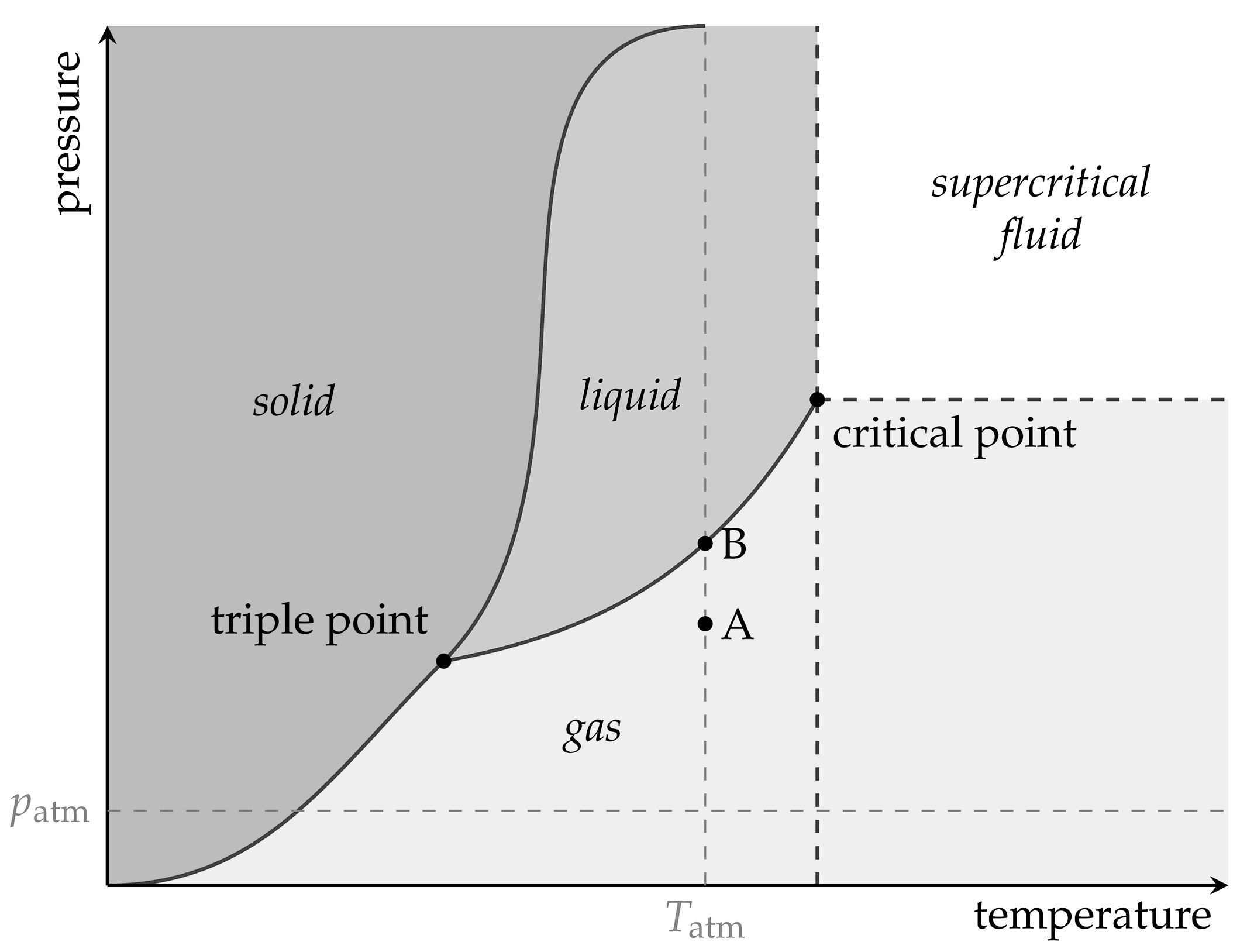
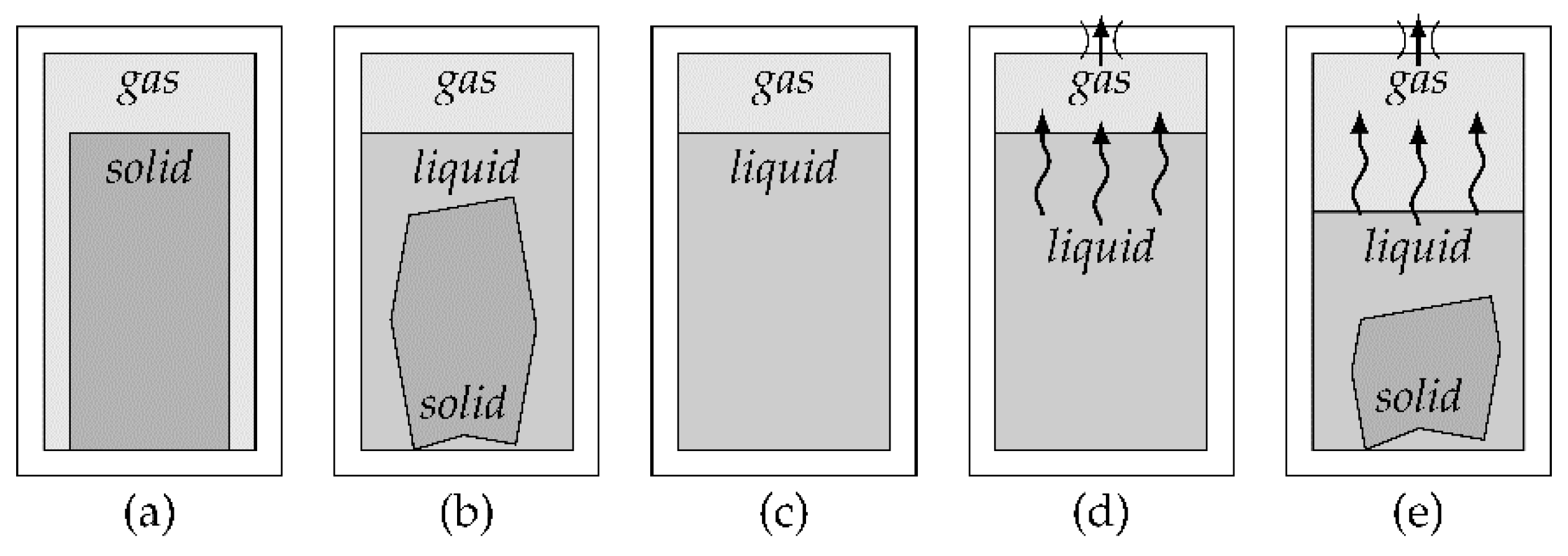
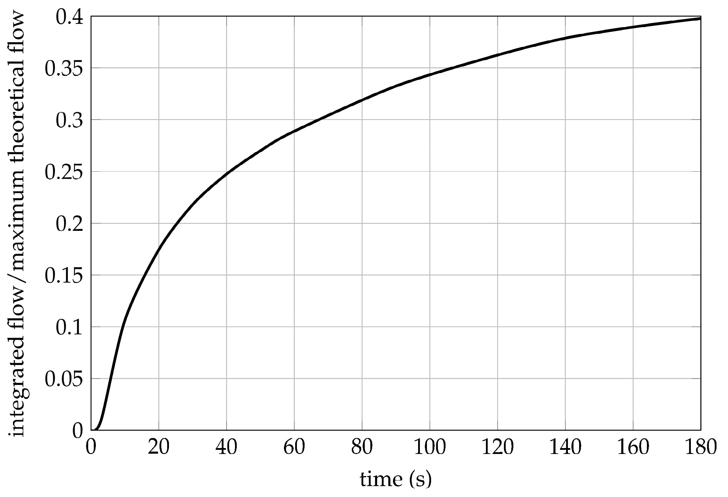
Table 1.
Experimental flow volumes and flow capacities achieved with the same compressor and battery setup at different working pressures, based on [23].
Table 1.
Experimental flow volumes and flow capacities achieved with the same compressor and battery setup at different working pressures, based on [23].
| Working Pressure (MPa) | Flow Volume (l) | Net Flow Capacity (m3/kg) | Gross Flow Capacity (m3/kg) |
|---|---|---|---|
| 0.1 | 1319 | 1.534 | 0.970 |
| 0.2 | 402 | 0.467 | 0.296 |
| 0.4 | 65.3 | 0.076 | 0.048 |
Table 2.
Key experimental values regarding pressure generation, flow rate, and flow capacities of small and large diaphragm compressors, based on [16].
Table 2.
Key experimental values regarding pressure generation, flow rate, and flow capacities of small and large diaphragm compressors, based on [16].
| Compressor Amount and Size, Setup | Maximum Pressure, No Flow (MPa) | Pressure at Peak Efficiency (MPa) | Maximum Flow Rate (l/min) | Net Flow Capacity (m3/kg) | Gross Flow Capacity (m3/kg) |
|---|---|---|---|---|---|
| 1 small | 0.2 | 0.1 | 2.6 | 2.02 | 1.38 |
| 2 small, parallel | 0.21 | 0.1 | 5.9 | 2.39 | 1.23 |
| 2 small, series | 0.34 | 0.15 | 3.6 | 1.51 | 0.78 |
| 1 large | 0.26 | 0.15 | 14.1 | 1.79 | 0.37 |
| 2 large, parallel | 0.27 | 0.15 | 27.3 | 1.74 | 0.20 |
| 2 large, series | 0.55 | 0.15 | 13.2 | 1.42 | 0.17 |
Table 3.
Experimental values for maximum efficiency and effective net and gross specific energy of small and large diaphragm compressors, based on [16].
Table 3.
Experimental values for maximum efficiency and effective net and gross specific energy of small and large diaphragm compressors, based on [16].
| Compressor Amount and Size, Setup | Maximum Efficiency (%) | Effective Net Specific Energy (kJ/kg) | Effective Gross Specific Energy (kJ/kg) |
|---|---|---|---|
| 1 small | 39.9 | 145.6 | 99.3 |
| 2 small, parallel | 36.7 | 152.9 | 79.2 |
| 2 small, series | 36.8 | 140.3 | 72.6 |
| 1 large | 40.3 | 160.0 | 33.6 |
| 2 large, parallel | 38.5 | 158.0 | 18.5 |
| 2 large, series | 31.2 | 126.6 | 14.8 |
Table 4.
Net and gross specific energies and calculated efficiency of the same compressor and battery setup at different working pressures, based on [23].
Table 4.
Net and gross specific energies and calculated efficiency of the same compressor and battery setup at different working pressures, based on [23].
| Working Pressure (MPa) | Effective Net Specific Energy (kJ/kg) | Effective Gross Specific Energy (kJ/kg) | Efficiency (%) |
|---|---|---|---|
| 0.1 | 106 | 66.8 | 25.3 |
| 0.2 | 51.4 | 32.5 | 12.3 |
| 0.4 | 12.3 | 7.77 | 2.9 |
Table 5.
Vessel mass per mass of fuel and net and gross flow capacities for air and carbon dioxide, based on [16].
Table 5.
Vessel mass per mass of fuel and net and gross flow capacities for air and carbon dioxide, based on [16].
| Substance | Pressure (MPa) | Tank Material | Vessel Mass per Mass of Fuel | Net Flow Capacity (m3/kg) | Gross Flow Capacity (m3/kg) |
|---|---|---|---|---|---|
| Air | 20 | Aluminum | 6.16 | 0.774 | 0.108 |
| Air | 30 | Aluminum | 7.03 | 0.774 | 0.096 |
| CO2 | 5.6 | Steel | 1.19 | 0.509 | 0.351 |
Table 6.
Specific energy per mass of fuel and mass of system for air and carbon dioxide, based on [16].
Table 6.
Specific energy per mass of fuel and mass of system for air and carbon dioxide, based on [16].
| Substance | Pressure (MPa) | Tank Material | Net Specific Energy (kJ/kg) | Gross Specific Energy (kJ/kg) |
|---|---|---|---|---|
| Air | 20 | Aluminum | 440.1 | 61.5 |
| Air | 30 | Aluminum | 473.7 | 59.0 |
| CO2 | 5.6 | Steel | 219.9 | 151.2 |
Table 7.
Pressure generation methods and corresponding first applications in soft robotics.
| No. | Pressure Generation Method | First Application | Source | Year |
|---|---|---|---|---|
| 1 | Battery-powered microcompressors | Walking robot | [6] | 2014 |
| 2 | Pressurized gas tanks | Active orthotic | [15] | 2012 |
| 3 | Phase change of carbon dioxide at the triple point | ‒ | ‒ | ‒ |
| 4 | Catalyzed chemical decomposition of hydrogen peroxide | Rolling robot | [7] | 2011 |
| 5 | Explosive combustion of hydrocarbons | Jumping robot | [11] | 2013 |
| 6 | Chemical reaction between citric acid and sodium bicarbonate | Artificial muscle | [19] | 2017 |
| 7 | Deflagration of sodium azide | ‒ | ‒ | ‒ |
| 8 | Reversible chemical reaction of water | Bending actuator | [39] | 2016 |
| 9 | Reversible chemical reaction between metal hydrides and hydrogen | Laminate bellows actuator | [40] | 2009 |
Table 8.
Quantitative evaluation and comparison of all presented pressure generation methods.
| No. | Pressure Generation Method | Gauge Pressure (MPa) | Initial Delay (s) | Net Flow Factor (1) | Net Flow Capacity (m3/kg) | Net Specific Energy (MJ/kg) |
|---|---|---|---|---|---|---|
| 1 | Battery-powered microcompressors | < 0.4 | < 5 | n.a. | 0.1−2.4 | 0.32−0.9 * |
| 2 | Pressurized gas tanks | 5−30 | < 1 | 50−300 | 0.5−0.8 | 0.2−0.5 |
| 3 | Phase change of carbon dioxide at the triple point | ~ 0.42 | > 60 | ~ 780 | ~ 0.5 | n.a. |
| 4 | Catalyzed chemical decomposition of hydrogen peroxide | < 30 | < 1 | 240−6600 | 0.16−4.6 | 1.45−2.9 |
| 5 | Explosive combustion of hydrocarbons | > 5 | < 1 | n.a. | n.a. | ~ 50 |
| 6 | Chemical reaction between citric acid and sodium bicarbonate | < 1.1 | 10−60 | ~ 320 | ~ 0.17 | n.a. |
| 7 | Deflagration of sodium azide | < 1 | < 5 | n.a. | n.a. | n.a. |
| 8 | Reversible chemical reaction of water | < 0.5 | > 60 | n.a. | n.a. | 0.32−0.9 * |
| 9 | Reversible chemical reaction between metal hydrides and hydrogen | < 10 | > 60 | n.a. | n.a. | 0.32−0.9 * |
* Depends on battery type; values for lithium polymer batteries are given.
Table 9.
Qualitative evaluation and comparison of all presented pressure generation methods.
| Pressure Generation Method (Numbers, See Table 7 and Table 8) | |||||||||
|---|---|---|---|---|---|---|---|---|---|
| Evaluation Criterion | 1 | 2 | 3 | 4 | 5 | 6 | 7 | 8 | 9 |
| Pressure variability | ◕ | ○ | ○ | ○ | ◑ | ○ | ◑ | ● | ● |
| Pressure sustainability | ● | ◑ | ● | ○ | ○ | ◔ | ◑ | ● | ● |
| Gas generation rate | ◑ | ● | ◕ | ◕ | ● | ◑ | ● | ○ | ● |
| Effective gross specific energy | ◔ | ◑ | ◔ | ◕ | ● | ◑ | ● | n.a. | n.a. |
| Safe handling and operation | ● | ◕ | ◑ | ◔ | ◔ | ◕ | ○ | ◕ | ◑ |
| Ecologically safe | ● | ● | ● | ◔ | ◑ | ● | ○ | ● | ◕ |
| Reusability | ● | ◕ | ◑ | ◑ | ◔ | ◑ | ◔ | ● | ● |
| Silent and vibrationless | ◔ | ● | ● | ● | ○ | ● | ○ | ● | ● |
| Simple and low-cost implementation | ◕ | ● | ◕ | ◔ | ○ | ◕ | ○ | ◑ | ○ |
© 2018 by the authors. Licensee MDPI, Basel, Switzerland. This article is an open access article distributed under the terms and conditions of the Creative Commons Attribution (CC BY) license (http://creativecommons.org/licenses/by/4.0/).
Share and Cite
MDPI and ACS Style
Adami, M.; Seibel, A. On-Board Pneumatic Pressure Generation Methods for Soft Robotics Applications. Actuators 2019, 8, 2. https://doi.org/10.3390/act8010002
AMA Style
Adami M, Seibel A. On-Board Pneumatic Pressure Generation Methods for Soft Robotics Applications. Actuators. 2019; 8(1):2. https://doi.org/10.3390/act8010002
Chicago/Turabian StyleAdami, Momme, and Arthur Seibel. 2019. "On-Board Pneumatic Pressure Generation Methods for Soft Robotics Applications" Actuators 8, no. 1: 2. https://doi.org/10.3390/act8010002
Note that from the first issue of 2016, this journal uses article numbers instead of page numbers. See further details here.