Thermodynamic Efficiency of Water Vapor/Solid Chemical Sorption Heat Storage for Buildings: Theoretical Limits and Integration Considerations


1
INSA–Lyon, Université de Lyon, CETHIL UMR5008 F–69621 Villeurbanne, France
2
UCBL, Université de Lyon, CETHIL UMR5008 F–69621 Villeurbanne, France
*
Author to whom correspondence should be addressed.
Appl. Sci. 2020, 10(2), 489; https://doi.org/10.3390/app10020489
Submission received: 6 April 2019
/
Revised: 18 May 2019
/
Accepted: 6 January 2020
/
Published: 9 January 2020
(This article belongs to the Special Issue The State of the Art of Thermo-Chemical Heat Storage)
Abstract
:Featured Application
The paper provides theoretical limits of chemisorption heat storage in buildings and discusses solutions for an efficient system integration.
Abstract
The theoretical limits of water sorbate-based chemical sorption heat storage are investigated in this study. First, a classification of thermochemical heat storage is proposed based on bonding typology. Then, thermodynamics of chemical solid/gas sorption is introduced. The analysis of the reaction enthalpy from the literature indicates that this value is only slightly varying for one mole of water. Using this observation, and with the help of thermodynamic considerations, it is possible to derive conclusions on energy efficiency of closed and open heat storage systems. Whatever the salt, the main results are (1) the energy required for evaporation of water is, at least, 65% of the available energy of reaction, and (2) the maximum theoretical energy efficiency of the system, defined as the ratio of the heat released to the building over the heat provided to the storage, is about 1.8. Considering the data from literature, it is also possible to show that perfectly working prototypes have an energy efficiency about 49%. Based on those results, it is possible to imagine that for the best available material, a perfect thermochemical heat storage system would correspond to 12 times water with a temperature difference about 50 °C. Such solution is definitely competitive, provided that some difficult issues are solved—issues that are discussed throughout this paper.

1. Introduction
It is obvious that everything has a limit. However, it is better to know its value to avoid wasting effort, time and money to find means of going beyond that limit. Chemical solid/gas reaction, i.e., thermochemical, can reach high thermal energy density. The first studies dealing with chemical heat storage are from the 1980s but it has become a real subject of interest during the last 10 years [1,2,3,4,5,6,7,8]. Among possible reactions, those using water are the most studied because of its availability and non-toxicity. Whatever the system, closed or open reactor, one of the main design criteria is the energy efficiency of the thermal storage system: this is the purpose of the present article.
Basically, thermal energy storage can be used for a wide range of applications [9]: for temperatures ranging from 600 °C in concentrated solar power to −20 °C for cooling; and for dimensions ranging from thousands of cubic meters to cubic millimeters. However, the most studied application remains building as it is an important leverage of energy consumption reduction. In buildings, the available heat can mainly come from solar energy or electrical energy. Therefore, the charging temperature of the storage system remains below 150 °C: only materials with a dehydration temperature below this limit will be considered. During the discharge, the system must provide the heat required for heating and/or domestic hot water production: these constraints will drive the power and temperature during the release of heat. The two main objectives of heat storage in buildings are (1) to store heat during the summer and release heat during cold days: interseasonal storage or (2) to store heat during electricity off-peak period and release heat during peak load: peak load shaving.
Now, let us have a look at the literature dealing with chemical reaction system efficiency. MgCl2·6H2O was selected by [10] to be tested in a 17 L open reactor. Under realistic operating condition, the energy storage capacity of the reactor reached about 139 kWh m−3. The energy efficiency was characterized by the instantaneous electrical COP of the system evaluated via:
where is the heat released and the fan electrical energy. A maximum electrical coefficient of performance of 12 was found, but the authors expected to reach up to 30 with by optimizing the heat recovery and decreasing the pressure drop in the storage. Of course this high COP value is a direct consequence of the “home-made” definition. For the sake of clarity and generalizability, the present study will only deal with thermodynamic efficiency of the system.
A laboratory scale closed chemical heat storage system was developed in [11], capable of holding about 974 g of material. The storage material used was SrBr2·6H2O and 13 dehydration and hydration cycles were conducted. The energy storage capacity of the reactor was about 65 kWh. The reactor thermal energy efficiency was 0.77 meaning a global heat loss of 23%.
It is worth mentioning that other reactors have been experimentally tested but no data are available concerning the energy efficiency:
The experimental investigation was focused on the reactor alone and the storage capacity and efficiency were based on a perfect system integration. For example, heat required for water vapor generation is never evaluated nor discussed. Further discussion on protype efficiency is discussed in Section 4 of the paper.
On the other side, the theoretical COP of chemical heat pump, i.e., closed system, was studied in [18]. The calculated standard enthalpy of reaction of 34 salts was used to evaluate the influence of thermophysical properties on energy and exergy efficiency of a perfect system with recovery of condensation heat and “energy–free” heat of vaporization. The main results were (1) the maximum COP is about 1.84 for CaSO4·2H2O and (2) the behavior of the energetic efficiency and the exegetic efficiency is opposite. The calculations were based on the evaluation of the perfect thermodynamic cycle.
The originality of the paper is the evaluation of the theoretical limits of the thermodynamic efficiency of water sorbate/salt chemical sorption heat storage system. To our knowledge, it is the first attempt to evaluate such limits. The starting point of our work is simple: examining data from the literature, the enthalpy of reaction of one mole of water varies little from one reaction to the other. Then, with the help of chemical thermodynamics, it is possible to derive general considerations concerning the efficiency of open and closed heat storage systems integrated in a building. Moreover, also considering the existing prototype data, more expanded conclusions are derived.
2. Heat Storage Classification
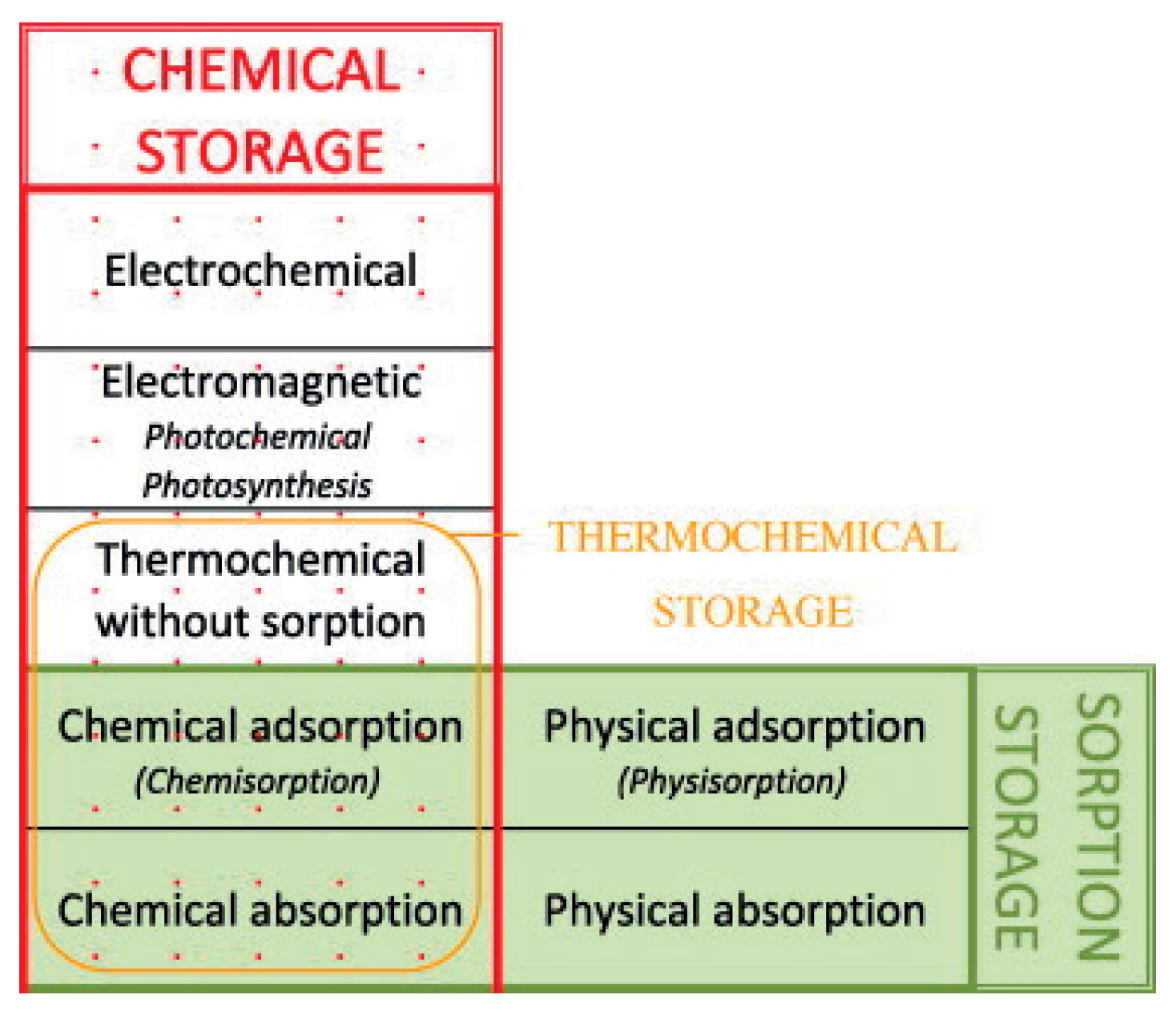
In the literature, thermochemical heat storage is employed for a family of reactions involving both physical and chemical processes. A tentative of classification is given in [19] and is presented in Figure 1. However, in this classification, sorption is used to aggregate different physical phenomena and can lead to misunderstandings. Then, we propose, in this section, to derive a classification of thermochemical heat storage based on physical phenomena typology. We deliberately limit the classification development to heterogeneous Involving components of two or more phases) reactions as homogeneous reactions are seldom used for thermal energy storage.
Let us first define sorption: according to [20], sorption is the process by which a substance (sorbate) is sorbed (adsorbed or absorbed) on or in another substance (sorbent). The process can be caused by physical bonding, i.e., physical sorption, or chemical bonding, i.e., chemical sorption. The main difference between physical and chemical sorption lies in the nature of created bonds. Physical sorption is weak, long range bonding mostly Van der Walls interactions and hydrogen bonding. Chemical sorption is strong, short range bonding involving orbital overlap and charge transfer. Another main difference between physical and chemical sorption is that the latter requires activation energy whereas it is not the case for the first process.
Sorption can be absorption or adsorption. Definitions of both processes can be found in [20]:
- Absorption is the process of one material (absorbate) being retained by another (absorbent); this may be the physical solution of a gas, liquid, or solid in a liquid, attachment of molecules of a gas, vapor, liquid, or dissolved substance to a solid surface by physical forces, etc..
- Adsorption is an increase in the concentration of a dissolved substance at the interface of a condensed and a liquid phase due to the operation of surface forces. Adsorption can also occur at the interface of a condensed and a gaseous phase.
While molecule undergoing absorption are taken up through the bulk of the absorbent (for example by diffusion), adsorption is a surface process. It is sometimes difficult to find the difference between adsorption and absorption. Taking for example the dehydration of lithium sulphate monohydrate [21] (i.e., chemical sorption), nucleation is supposed to occur at the surface of the grain (adsorption) and then the growth proceeds towards the center of the grains by diffusion (absorption).
Physical sorption can be split into absorption and adsorption (also called physisorption). As with physical sorption, chemical sorption can be split into absorption and adsorption:
- Chemical absorption or reactive absorption is a chemical reaction between the absorbed and the absorbing substances. Sometimes it combines with physical absorption. This type of absorption depends upon the stoichiometry of the reaction and the concentration of its reactants.
- Chemical adsorption is called chemisorption. Chemisorption is Adsorption which results from chemical bond formation (strong interaction) between the adsorbent and the adsorbate in a monolayer on the surface [20].
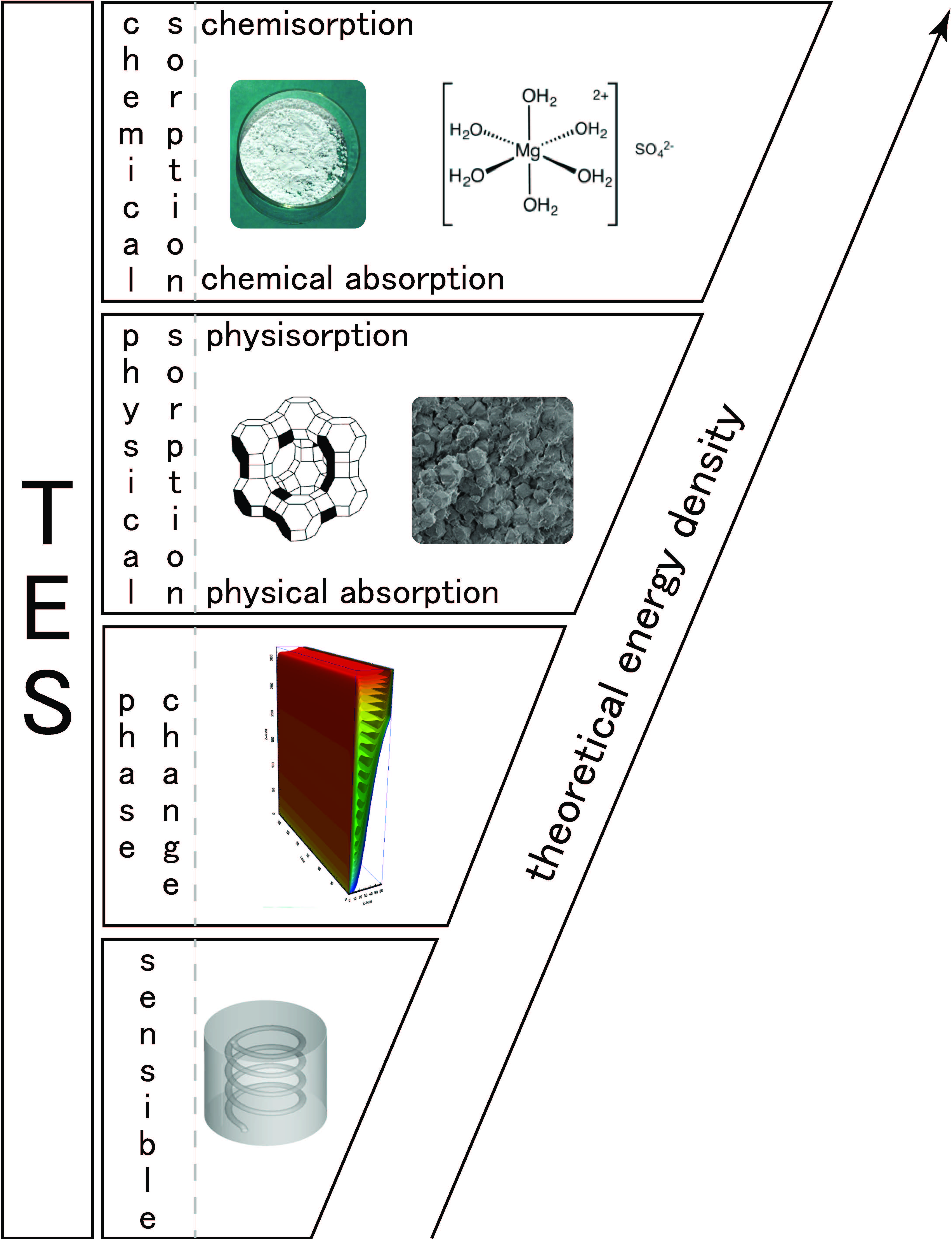
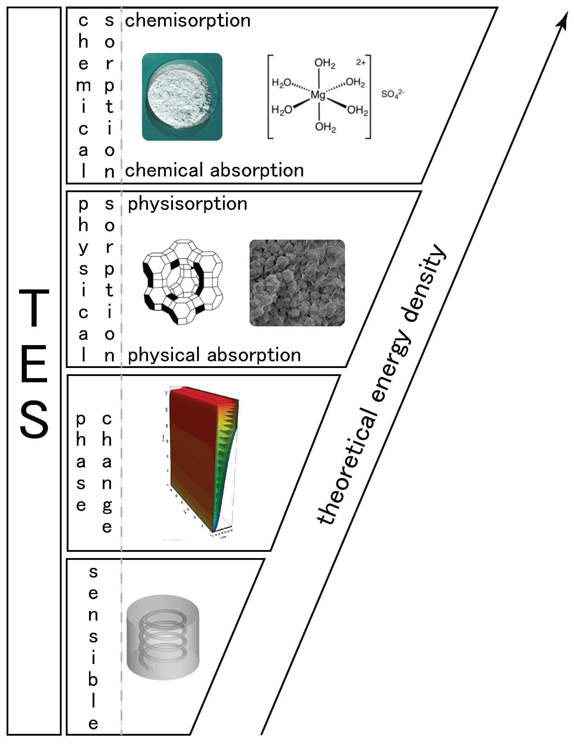
From the previous definition, we propose in Figure 2 a classification of heat storage systems based on the physical/chemical phenomena involved. For heat storage, the split between physical and chemical sorption is important as the heat related to the two phenomena is quite different. For example, heat of adsorption is different for physisorption and chemisorption:
3. Basics of Chemical Thermodynamics
3.1. Energy Change in Chemical Sorption
Let us consider the water sorbate heterogeneous chemical sorption reaction process expressed under the following general form:
The first law of thermodynamics states that the change in the internal energy of a system is equal to the sum of the heat gained/lost by the system Q and the work done by/on the system W:
The amount of work of expansion done by the reaction during any transformation is given by:
At constant volume (i.e., ), the heat released or absorbed by the reaction is equal to the change in the internal energy that occurs during the reaction:
Such configuration is close to closed chemical sorption heat storage systems.
At constant pressure, the change in the internal energy during the reaction is given by:
Let us introduce the enthalpy of the system H related to the internal energy by:
Then, the heat released or absorbed during a chemical reaction at constant pressure is equal to the change in the enthalpy of the system:
Such configuration is close to open chemical sorption heat storage systems.
The relationship between the change in internal energy and the change in enthalpy, assuming an ideal gas, is given by:
where is the gas constant and the stoichiometric coefficient defined in Equation (2). For a temperature of 273.15 K, . This value is very low compared to the heat of reaction given per mole of water Values of enthalpies of reaction are given in Table 1), less than 4%, and then can be neglected. Consequently, it is possible to assume that the change in internal energy is more or less equal to the change in enthalpy.
3.2. Enthalpy of Reaction
For the reaction given in Equation (2), , and are respectively the mole variation of water, solid A (i.e., dehydrated salt) and solid (i.e., hydrated salt). Then, the degree of advancement of the reaction is given by:
The variation of enthalpy can be written under the following form:
where is the enthalpy of reaction at constant temperature and pressure. Of course, for a transformation at constant pressure and temperature (Constant temperature or neglected variation of enthalpy due to temperature change), the variation of enthalpy is given by
The standard enthalpy of reaction (denoted ) is the enthalpy change that occurs in a system when one mole of matter is transformed by a chemical reaction under standard conditions, i.e., a temperature of 273.15 K and a pressure of 100,000 Pa. The standard enthalpy of reaction can be measured or computed using the standard enthalpy of formation of the reactants and products.
The enthalpy of reaction for a temperature T is related to the standard enthalpy of reaction via:
where C is the specific heat of , A or H2O. It is worth mentioning that usually, the quantity is small compared to .
Moreover, the chemical sorption reaction being monovariant, the equilibrium is given by the Clausius–Clapeyron relation:
where is the equilibrium water vapor pressure [] and the equilibrium temperature [].
4. Material Considerations
In the remaining of the study, we will consider only reactions involving temperatures below 150 °C which corresponds to a building application [1]. However, the ideas developed in the present paper can be straightforwardly adapted to other applications or other sorbates.
The dehydration of cobalt(II) chloride–6–hydrate (CoCl2.6H2O) was investigated in [24]. The enthalpy of formation was calculated using thermodynamic values. The results show that one mole of water corresponds to a variation of the reaction enthalpy about 55.2 kJ mol−1. It is worth mentioning that the latter value is very close to the enthalpy of vaporization of ice at 25 °C i.e., 52 kJ mol−1. This conclusion is also validated by [25].
Enthalpy of reaction given in the literature are summarized in Table 1. The enthalpy of reaction of one mole of water is only varying between 55.1 kJ mol−1 and 67.8 kJ mol−1. Of course, this value is close to the observations made in the literature and given above. This observation is the starting point of our demonstration concerning the maximum efficiency of a chemical sorption heat storage integrated in a building.

Table 1.
Measured enthalpy of reaction extracted from the literature.
| Hydrated Salt | Dehydrated Salt | [kJ mol−1] | [kJ mol−1] | Reference |
|---|---|---|---|---|
| MgSO4·6H2O | MgSO4·H2O | 275.7 | 55.1 | [26] |
| LiNO3·3H2O | LiNO3 | 165.8 | 55.3 | [27] |
| Al2(SO4)3·18H2O | Al2(SO4)3·8H2O | 554.5 | 55.4 | [27] |
| CaCl2·6H2O | CaCl2·H2O | 277.0 | 55.4 | [27] |
| CuSO4·5H2O | CuSO4·3H2O | 111.7 | 55.8 | [26] |
| SrCl2·6H2O | SrCl2 | 342.0 | 57.0 | [27] |
| LiSO4·H2O | LiSO4 | 57.2 | 57.2 | [26] |
| CuSO4·3H2O | CuSO4·H2O | 114.8 | 57.4 | [26] |
| La(NO3)3·6H2O | La(NO3)3·1·5H2O | 260.4 | 57.9 | [27] |
| MgCl2·6H2O | MgCl2·4H2O | 116.4 | 58.2 | [26] |
| LaCl3·7H2O | LaCl3·H2O | 355.5 | 59.3 | [27] |
| Na2S2O3·5H2O | Na2S2O3 | 279.9 | 56.0 | [27] |
| MgSO4·7H2O | MgSO4·H2O | 335.7 | 56.0 | [27] |
| CaCl2·2H2O | CaCl2·0·3H2O | 101.0 | 59.4 | [28] |
| MgCl2·6H2O | MgCl2 | 361.2 | 60.2 | [29] |
| KOH·2H2O | KOH·1·2H2O | 48.2 | 60.3 | [27] |
| Zn(NO3)2·6H2O | Zn(NO3)2 | 372.0 | 62.0 | [27] |
| Na2S·5H2O | Na2S | 310.0 | 62.0 | [30] |
| CaBr2·6H2O | CaBr2·0·3H2O | 353.9 | 62.1 | [27] |
| LiCl·H2O | LiCl | 62.2 | 62.2 | [27] |
| K2CO3·1·5H2O | K2CO3 | 95.5 | 63.7 | [27] |
| SrBr2·6H2O | SrBr2·H2O | 337.0 | 67.4 | [27] |
| MgCl2·4H2O | MgCl2·2H2O | 135.6 | 67.8 | [26] |
5. Efficiency: From Material to System
5.1. Concepts
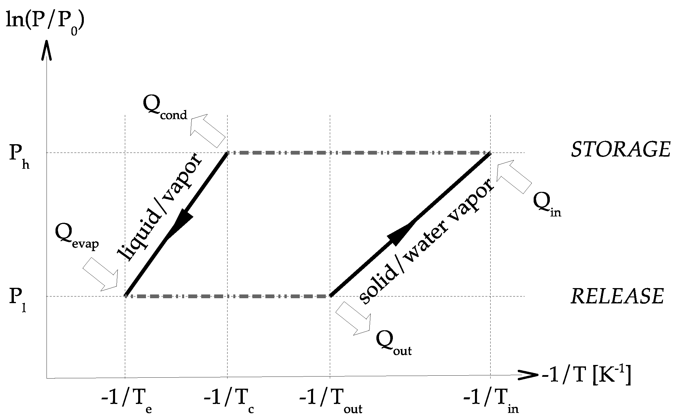
The principle diagram of a perfect sorption heat storage system using solid–water vapor chemisorption is presented in Figure 3. The 2 curves present the solid/water vapor equilibrium of the sorbent and the vapor/liquid equilibrium of the water sorbate. Under the solid/water vapor line, the sorbent is under the form. Above the solid/water vapor line, the sorbent is under the form. Basically, the two main concepts of system design are closed and open.
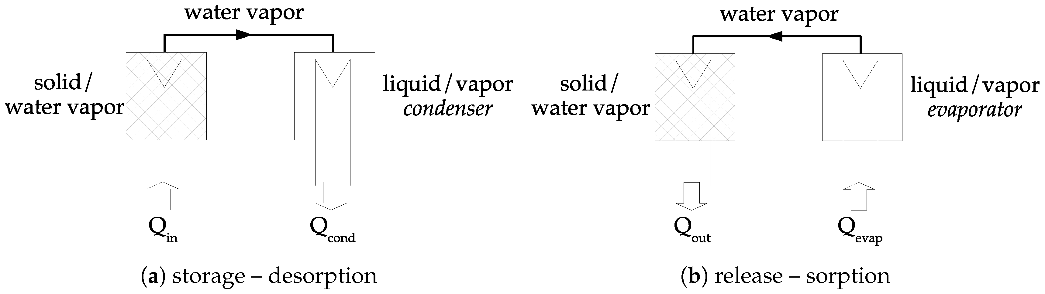
The concept of closed chemical sorption thermal energy storage system is given in Figure 4. At the beginning, sorbent is under the form. During the storage step, heat is transferred to the solid at the temperature . Therefore, dehydration occurs, and water vapor pressure is increasing. Consequently, the gas moves from the material to the condenser where the pressure is . The vapor condensates (in the condenser) and heat of condensation is released, . During the release step, liquid is evaporated (in the evaporator) at temperature , requiring energy, . The pressure in the evaporator is higher than in the solid and a vapor flow stands. Thermal energy is then released during the sorption reaction in the solid.
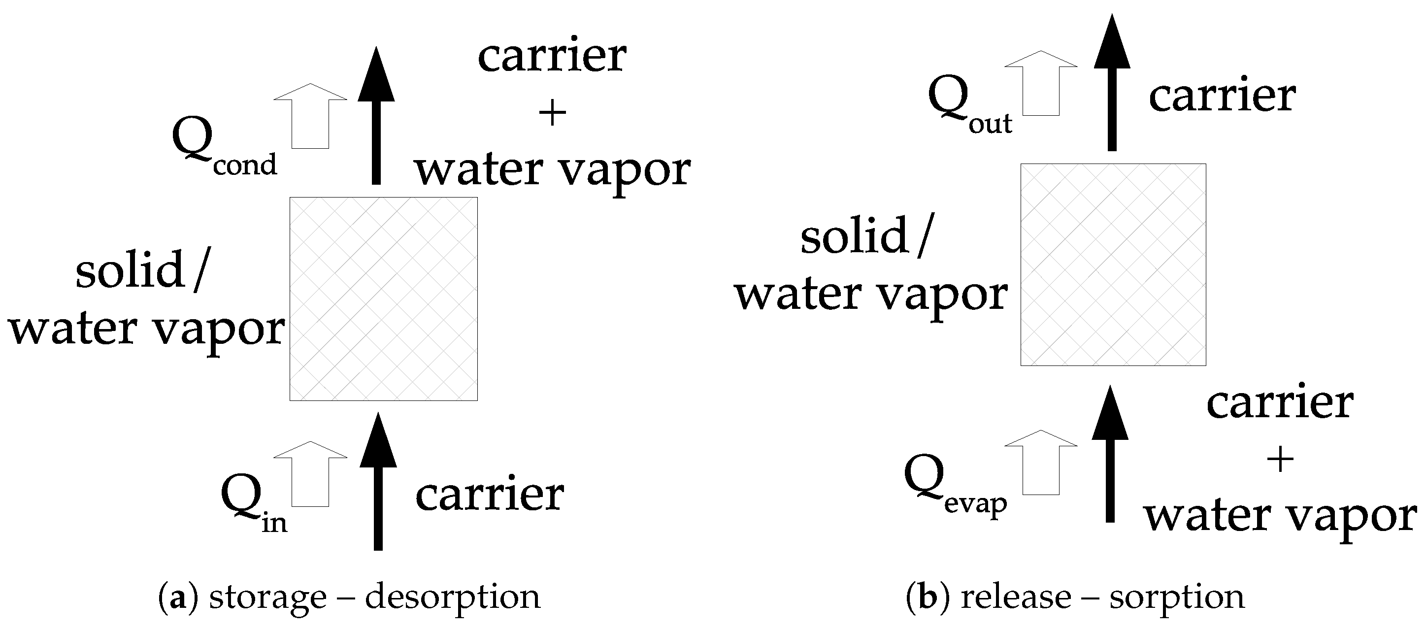
The other option consists of using an open system; a principle diagram of such system is given in Figure 5. The concept consists of using dry air (inert from the reaction point of view) and water vapor (i.e., humid air). During the storage step, the humid air is passing through the material under the form. thermal energy is then transferred to the solid at the temperature , resulting in the dehydration process and a potential heat of condensation in the carrier, . During the release step, humid air is passing through the material under the form and may requires a quantity of heat to evaporate liquid water, . The water vapor is sorbed and a quantity of thermal energy is transferred to the humid air.
In a closed system, a water tank with a heat exchanger is necessary. It behaves either like a condenser, or like an evaporator, depending on the storage or release step. In an open system, it is necessary to find the water vapor. In most of the publications, it is stated that this humidity can come from inside the building. However, calculations show that it is not enough water vapor, especially in wintertime when outside specific humidity is very low.
5.2. Literature Review
5.2.1. Closed Systems
A thermochemical heat pump based on the SrBr2 salt was developed for the aim of both heating and cooling in [12]. The prototype is able to store 60 kWh m−3 and 40 kWh m−3 respectively for heating and cooling. The specific powers for heating and cooling is in the range 2.5 kW m−3 to 4 kW m−3. The main limitation identified by the authors was the low heat transfer at the interface between the reactive layer and the exchanger wall.
Na2S was the salt used in [31] to develop a modular heat storage system. The average heating power is 3.79 kW and energy released about 0.5 kWh. The calculations do not take into account the energy required for water vaporization during adsorption.
A closed system using MgCl2 has been numerically studied in [29]. In this work, the material with the heat exchanger is modeled using Comsol Multiphysics 4.3a to evaluate the thermal and mass transport behavior of salt-hydrate during charging process. From the model, it is also possible to evaluate the temperature field in the reactor and possible problems of melting.
5.2.2. Open Systems
Pure salt thermochemical heat storage has been studied in laboratory with the design and test of a prototype using the hydration of the strontium bromide SrBr2 [15,32]. They report in their study that hydration specific powers up to 4.3 kW m−3 and an energy density of 190 kWh m−3 has been reached for a theoretical bed salt energy density of 388 kWh m−3.
KAI(SO4)2 has been tested in a reactor of 25 kg of salt [33]. The results are an energy density of 0.2 kW kg and a power density of 4 W kg.
In [10], a selection procedure was realized to select the material tested MgCl2. A prototype of 17 dm3 has been tested in laboratory conditions. The prototype was able to provide 50 W heating power at 60 °C, with an instantaneous COP of 12, i.e., a density about 3 kW m−3. The authors also highlighted that the improvement of heat recovery and pressure drop could increase the performance.
A composite MgSO4 salt inside zeolite reactor of 7.1 dm3 was monitored during hydration and dehydration in [34]. The results are a released power of 64 W for an energy of 636 kWh meaning a released power density of 9 kW m−3 and an energy density of 90 kWh m−3.
5.3. Discussion
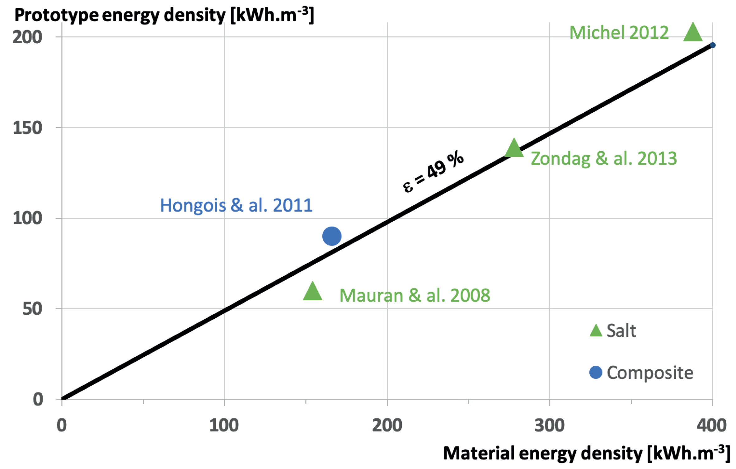
Figure 6 is summarizing the results under the form of the prototype energy density versus the material energy density, of course for the available data. The main result is that whatever the material, the perfect laboratory scale reactor energy density is about 49% of the material alone! Improvements are necessary to increase this efficiency, based on heat and mass transfers. Of course, those measurements are realized under perfect boundary conditions without considering the reactor integration in the building. In particular, the way the water vapor is produced and the way the water condensation energy is recovered has a high impact on the final maximum energy efficiency. This is the purpose of the next section.
6. Thermodynamic Efficiency: From System to Integration in Buildings
Whatever the system, open or closed, it is important to answer the issue related to the thermodynamic efficiency limit of the heat storage. Basically, the designer of such system must know the thermodynamics limit to evaluate the enhancement possibilities of its prototype.
Let us first define as the supplied energy per mole of salt to the storage system and as the recovered energy per mole of salt. For the sake of universality, the efficiency of the system is defined as:
This efficiency can also be found as COP in the literature [3]. However, the definition of COP may vary from one author to the other: an example is the definition of COP given by [10] which is completely different from the one given by [18].
The maximum reachable efficiency is calculated with the maximum , called , and, of course, the minimum .
The assumptions used to evaluate the theoretical limits of the energy efficiency are:
- ○
- Heat losses in the system are not taken into account.
- ○
- Sensible heat of materials and parts of the reactor are neglected.
- ○
- The energy released or absorbed by the reaction is approximated by the standard enthalpy of reaction.
- ○
- The equilibrium drop influence is neglected (see [18]).
- ○
- Only total hydration/dehydration processes are under investigation.
Given the previous assumptions, if the heat of condensation is not recovered and if the heat of evaporation is energy–free (Energy–free means that no additional energy is required for producing water vapor), the trivial efficiency is (see Figure 7—).
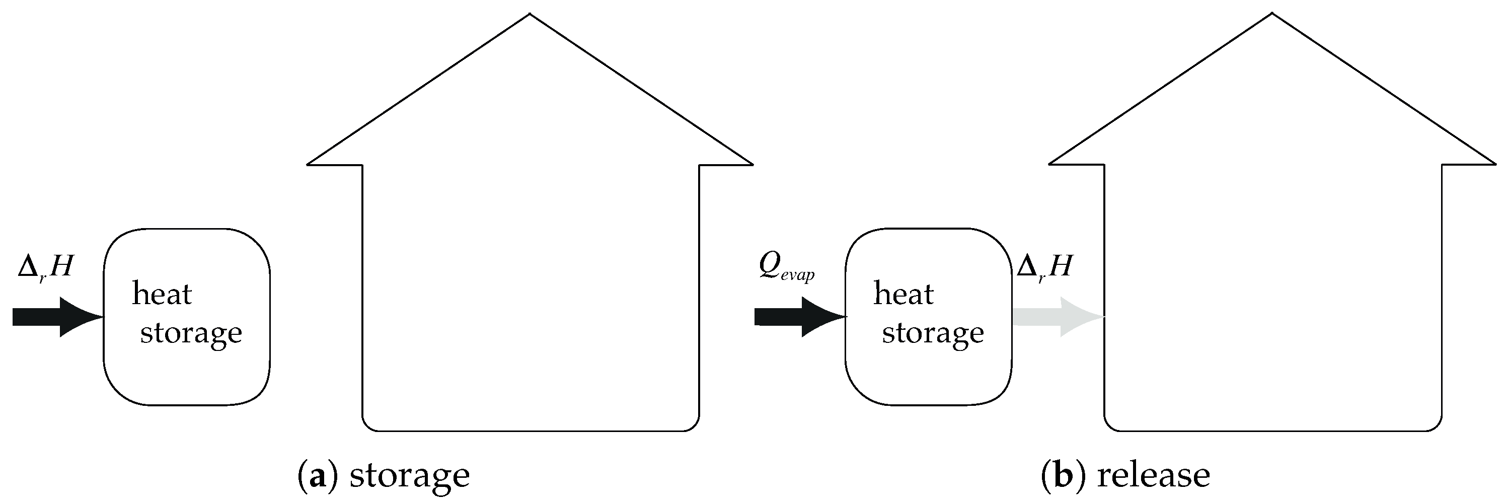
Considering the previous assumptions, if non-free heat of evaporation, the maximum efficiency becomes (see Figure 8):
The quantity of energy required to evaporate liquid water per mole of salt is evaluated with:
where is the water heat of vaporization in standard conditions taken as 2456 kJ kg−1 and the molar mass of water equal to 18 g mol−1. Considering data from Table 1, and considering that is varying between 55.1 kJ mol−1 and 67.8 kJ mol−1, the ratio can be straightforwardly evaluated as:
The previous equations also show that energy required for evaporation is, at least, 65% of the available energy of reaction! And the maximum energy efficiency of the integrated system is 60% only!
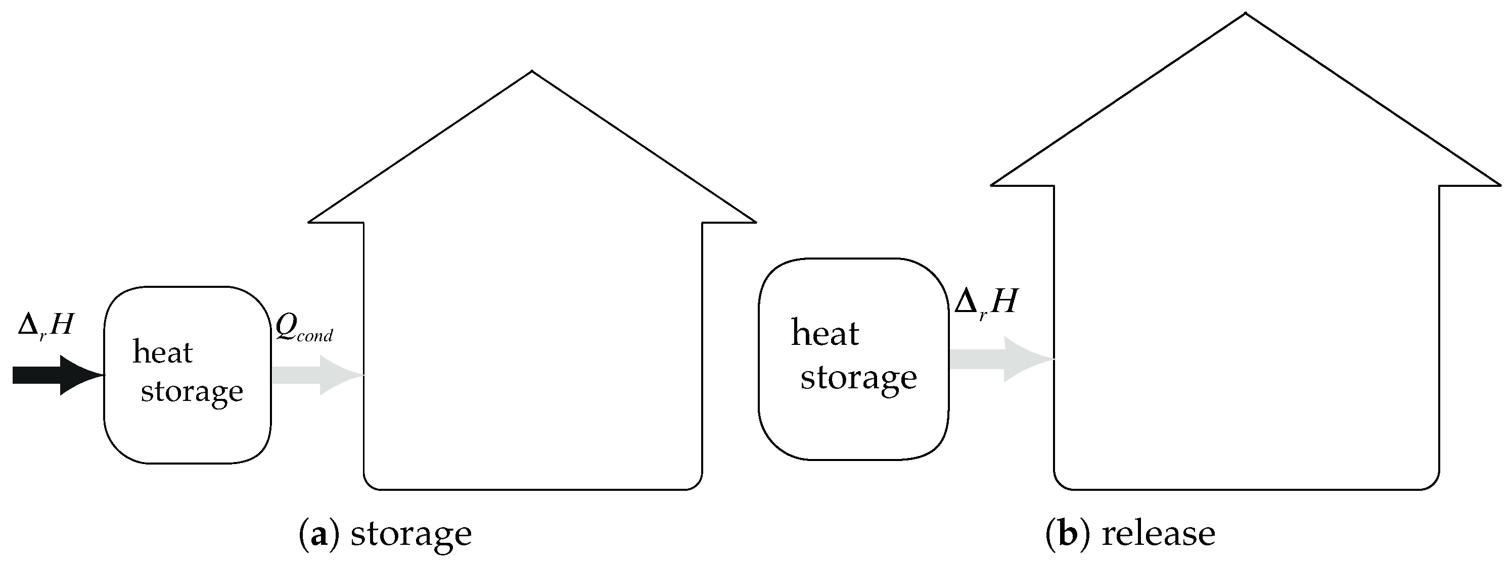
Let us now consider the case with a total recover of condensation heat and energy–free heat of evaporation. Then, the energy efficiency becomes (see Figure 9):
The quantity of energy (per mole of salt) recoverable from condensation is evaluated by:
Starting from Equation (19) and introducing Equation (20), the energy efficiency of the system becomes:
The maximum theoretical energy efficiency of the system is about 1.8, whatever the salt! This conclusion is clearly in accordance with the results of [18] where the maximum value is 1.84. However, our study extends these results to the integration of an open system. Our study also highlights the necessity to work on the system integration as the conclusions are valid whatever the salt.
7. Conclusions
Chemical materials are available for heat storage in buildings with reaction temperatures in agreement with the available heat. For safety reasons, those materials are non-toxic and use water for reacting. From a selection of available data, the most promising material is magnesium sulphate with an energy density of 780 kWh m−3.
From material to reactor, perfect reactor, the efficiency is 49%, meaning that for magnesium sulphate, the maximum reactor prototype energy density would be 382 kWh m−3. Of course, there still some development to realize to increase the ratio between perfect reactor and material energy densities. Another issue that is not under consideration presently in scientific literature, would be to pass from the lab scale prototype to large, or real, scale reactor.
Regarding data from the literature, the reaction enthalpy of one mole of water only varies between 55.1 kJ mol−1 and 67.4 kJ mol−1. Considering an open or closed single-stage system, the two main conclusions are:
- Energy required for evaporation of water is, at least, 65% of the available energy of reaction.
- For a perfect system, the maximum theoretical energy efficiency of the system is about 1.8.
Dealing with the integration of the system in a building, two main issues appear, related to the water vapor origin and the heat of condensation. If the water vapor is not energy-free and if the heat of condensation is not used, then the maximum efficiency is 65%. For a perfect magnesium sulphate reactor, the maximum energy density becomes 229 kJ mol−1. It corresponds to 4 times water with a temperature difference about 50 °C. In that case, the difference is too low for magnesium sulphate to be competitive. However, if water vapor is energy-free and if the heat of condensation is recovered, then the maximum energy efficiency becomes 180%. For a perfect magnesium sulphate reactor, the maximum energy density becomes 688 kJ mol−1. It corresponds to 12 times water with a temperature difference about 50 °C. Such solution can definitely be competitive!
The previous conclusions do not depend on the adsorbent material considered. Then, a special attention must be paid on the system for:
- Developing water evaporation system “energy–free” or low–energy for the discharging phase.
Of course, these theoretical limits remain valid for the operating conditions given in this work and further studies must be carried to extend the conclusions to higher temperature storage. Moreover, numerical modeling is also under investigation to evaluate the potential improvement of the system integrated in the building.
Author Contributions
State of the art, F.K., K.J.; writing–original draft preparation, F.K.; writing–review and editing, K.J., F.K. All authors have read and agreed to the published version of the manuscript.
Funding
This project was funded by the DECARTH 2016 project ANR-16-CE22-0006-01 of the French National Research Agency.
Conflicts of Interest
The author declares no conflict of interest.
Abbreviations
| List of Symbols | ||
| C | specific heat capacity | J kg−1 K−1 |
| H | enthalpy | J |
| vaporization heat of water | J kg−1 | |
| P | pressure | Pa |
| Q | heat energy per mole of salt | Jmol−1 |
| R | gas constant | J K−1 mol−1 |
| S | entropy | J |
| T | temperature | K |
| U | internal energy | J |
| V | volume | m3 |
| W | work | J |
| Greek letters | ||
| stoechiometric coefficient | ||
| efficiency | ||
| advancement of reaction | ||
| Subscript | ||
| e | equilibrium | |
| evaporation | ||
| maximum | ||
| minimum | ||
| r | reaction | |
| 0 | standard | |
| Superscript | ||
| 0 | standard | |
| − | recovered energy | |
| + | supplied energy | |
References
- Kuznik, F.; Johannes, K.; Obrecht, C. Chemisorption heat storage in buildings: State–of–the–art and outlook. Energy Build. 2015, 106, 183–191. [Google Scholar] [CrossRef]
- Prieto, C.; Cooper, P.; Fernandez, A.I.; Cabeza, L. Review of technology: Thermochemical energy storage for concentrated solar power plants. Renew. Sustain. Energy Rev. 2016, 60, 909–929. [Google Scholar] [CrossRef] [Green Version]
- Sole, A.; Martorell, I.; Cabeza, L. State of the art on gas–solid thermochemical energy storage systems and reactors for building applications. Renew. Sustain. Energy Rev. 2015, 47, 386–398. [Google Scholar] [CrossRef] [Green Version]
- Cot-Gores, J.; Castell, A.; Cabeza, L. Thermochemical energy storage and conversion: A–state–of–the–art review of the experimental research under practical conditions. Renew. Sustain. Energy Rev. 2012, 16, 5207–5224. [Google Scholar] [CrossRef]
- Andre, L.; Abanades, S.; Flamant, G. Screening of thermochemical systems based on solid-gas reversible reactions for high temperature solar thermal energy storage. Renew. Sustain. Energy Rev. 2016, 64, 703–715. [Google Scholar] [CrossRef]
- Aydin, D.; Casey, S.P.; Riffat, S. The latest advancements on thermochemical heat storage systems. Renew. Sustain. Energy Rev. 2015, 41, 356–367. [Google Scholar] [CrossRef]
- Cabeza, L.; Sole, A.; Barreneche, C. Review on sorption materials and technologies for heat pumps and thermal energy storage. Renew. Energy 2017, 110, 3–39. [Google Scholar] [CrossRef] [Green Version]
- Kuznik, F. Chemisorption heat storage for solar low-energy buildings. In Advances in Solar Heating and Cooling; Wang, R.Z., Ge, T.S., Eds.; Woodhead Publishing: Cambridge, UK, 2016; pp. 467–487. [Google Scholar]
- Dincer, I.; Rosen, M. Thermal Energy Storage: Systems and Applications; Wiley: Hoboken, NJ, USA, 2010; 620p. [Google Scholar]
- Zondag, H.; Rikkert, B.; Smeding, S.; de Boer, R.; Bakker, M. Prototype thermochemical heat storage with open reactor system. Appl. Energy 2013, 109, 360–365. [Google Scholar] [CrossRef]
- Fopah-Lele, A.; Rohde, C.; Neumann, K.; Tiejen, T.; Ronnebeck, T.; N’Tsoukpoe, K.E.; Osterl, T.; Opel, O.; Ruck, W.K. Lab-scale experiment of a closed thermochemical heat storage system including honeycomb heat exchanger. Energy 2016, 114, 225–238. [Google Scholar] [CrossRef]
- Mauran, S.; Lahmidi, H.; Goetz, V. Solar heating and cooling by a thermochemical process. First experiments of a prototype storing 60 kW h by a solid/gas reaction. Sol. Energy 2008, 82, 623–636. [Google Scholar] [CrossRef]
- De Jong, A.J.; van Vliet, L.; Hoegaerts, C.; Roel, S.M.; Cuypers, R. Thermochemical Heat Storage—From Reaction Storage Density to System Storage Density. Energy Proc. 2016, 91, 128–137. [Google Scholar] [CrossRef] [Green Version]
- Michel, B.; Mazet, N.; Neveu, P. Experimental investigation of an open thermochemical process operating with a hydrate salt for thermal storage of solar energy: Local reactive bed evolution. Appl. Energy 2016, 180, 234–244. [Google Scholar] [CrossRef]
- Michel, B.; Mazet, N.; Neveu, P. Experimental investigation of an innovative thermochemical process operating with a hydrate salt and moist air for thermal storage of solar energy: Global performance. Appl. Energy 2014, 129, 177–186. [Google Scholar] [CrossRef] [Green Version]
- Richter, M.; Bouche, M.; Linder, M. Heat transformation based on CaCl2/H2O—Part A: Closed operation principle. Appl. Therm. Eng. 2016, 102, 615–621. [Google Scholar] [CrossRef] [Green Version]
- Bouche, M.; Richter, M.; Linder, M. Heat transformation based on CaCl2/H2O—Part B: Open operation principle. Appl. Therm. Eng. 2016, 102, 641–647. [Google Scholar] [CrossRef] [Green Version]
- Obermeier, J.; Muller, K.; Arlt, W. Thermodynamic analysis of chemical heat pumps. Energy 2015, 88, 489–496. [Google Scholar] [CrossRef]
- N’Tsoukpoe, K.E.; Liu, H.; Le Pierres, N.; Luo, L. A review on long-term sorption solar energy storage. Renew. Sustain. Energy Rev. 2009, 13, 2385–2396. [Google Scholar] [CrossRef]
- McNaught, A.D.; Wilkinson, A. IUPAC Compendium of Chemical Terminology, 2nd ed.; Wiley Blackwell: Hoboken, NJ, USA, 1997. [Google Scholar]
- Valdivieso, F.; Bouineau, V.; Pijolat, M.; Soustelle, M. Kinetic study of the dehydration of lithium sulphate monohydrate. Renew. Solid State Ion. 1997, 101–103, 1299–1303. [Google Scholar] [CrossRef]
- Bolis, V. Fundamentals in Adsorption at the Solid-Gas Interface. Concepts and Thermodynamics. In Calorimetry and Thermal Methods in Catalysis; Auroux, A., Ed.; Springer: Berlin/Heidelberg, Germany, 2013; pp. 3–50. [Google Scholar]
- Gottfried, J.M. CO Oxidation Over Gold. Ph.D. Thesis, Freien Universitat Berlin, Berlin, Germany, 2003. [Google Scholar]
- Grindstaff, W.K.; Fogel, N. Thermochemistry of cobalt(II) chloride hydrates. J. Chem. Soc. Dalton Trans. 1972, 1476–1481. [Google Scholar] [CrossRef]
- Mishra, S.K.; Kanungo, S.B. Thermal dehydration and decomposition of nickel chloride hydrate NiCl2·H2O. J. Therm. Anal. 1992, 38, 2417–2436. [Google Scholar] [CrossRef]
- Ferchaud, C.J.; Zondag, H.A.; de Boer, R.; Rindt, C. Characterization of the sorption process in thermochemical materials for seasonal solar heat storage application. In Proceedings of the 12th International Conference on Energy Storage, Lleida, Spain, 16–18 May 2012. [Google Scholar]
- N’Tsoukpoe, K.E.; Schmidt, T.; Rammelberger, H.U.; Watts, B.A.; Rick, W.K. A systematic multi–step screening of numerous salt hydrates for low temperature thermochemical energy storage. Appl. Energy 2014, 124, 1–16. [Google Scholar] [CrossRef]
- Molenda, M.; Stengler, J.; Linder, M. Reversible hydration behavior of CaCl2 at high H2O partial pressures for thermochemical energy storage. Thermochim. Acta 2013, 560, 76–81. [Google Scholar] [CrossRef]
- Fopah-Lele, A.; Kuznik, F.; Rammelberger, H.U.; Schmidt, T.; Ruck, W.K. Thermal decomposition kinetic of salt hydrates for heat storage systems. Appl. Energy 2015, 154, 447–458. [Google Scholar] [CrossRef]
- De Boer, R.; Haije, W.; Veldhuis, J. Determination of structural, thermodynamic and phase properties in the Na2S–H2O system for application in a chemical heat pump. Thermochim. Acta 2002, 395, 3–19. [Google Scholar] [CrossRef]
- Iammak, K.; Wongsuwan, W.; Kiatsiroroi, W. Investigation of Modular Chemical Energy Storage Performance. In Proceedings of the Joint International Conference on Sustainable Energy and Environment, Hua Hin, Thailand, 1–3 December 2004; pp. 504–507. [Google Scholar]
- Michel, B.; Mazet, N.; Mauran, S.; Stitou, D. Thermochemical process for seasonal storage of solar energy: Characterization and modeling of a high density reactive bed. Energy 2012, 47, 553–563. [Google Scholar] [CrossRef] [Green Version]
- Marias, F.; Tanguy, G.; Wyttenbach, J.; Rouge, S.; Papillon, P. Thermochemical storage: First results of pilot storage with moist air. In Proceedings of the ISES 2011, Kassel, Germany, 28 August–2 September 2011. [Google Scholar]
- Hongois, S.; Kuznik, F.; Steven, P.; Roux, J.J. Development and characterisation of a new MgSO4/zeolite composite for long-term thermal energy storage. Sol. Energy Mater. Sol. Cells 2011, 95, 1831–1837. [Google Scholar] [CrossRef]
- Li, T.; Wu, S.; Yan, T.; Xu, J.; Wang, R. A novel solid-gas thermochemical multilevel sorption thermal battery for cascaded solar thermal energy storage. Appl. Energy 2016, 161, 1–10. [Google Scholar] [CrossRef]
- N’Tsoukpoe, K.E.; Mazet, N.; Neveu, P. The concept of cascade thermochemical storage based on multimaterial system for household applications. Renew. Energy 2016, 129, 138–149. [Google Scholar]
Figure 1.
Chemical storage and sorption storage classification—reproduced from [19], copyright permission: Elsevier, 2019.
Figure 1.
Chemical storage and sorption storage classification—reproduced from [19], copyright permission: Elsevier, 2019.

Figure 2.
Classification of heat storage by physical phenomena.

Figure 3.
Theoretical Clausius–Clapeyron chemical sorption cycle – reproduced from [1], copyright permission: Elsevier, 2019.
Figure 3.
Theoretical Clausius–Clapeyron chemical sorption cycle – reproduced from [1], copyright permission: Elsevier, 2019.

Figure 4.
Closed heat storage system—quantities refer to Figure 3—reproduced from [1], copyright permission: Elsevier, 2019.

Figure 5.
Open heat storage system—quantities refer to Figure 3—reproduced from [1], copyright permission: Elsevier, 2019.

Figure 6.
Prototype energy density versus material energy density.

Figure 7.
System integration: heat of condensation is not recovered, and heat of evaporation is energy–free: .
Figure 7.
System integration: heat of condensation is not recovered, and heat of evaporation is energy–free: .
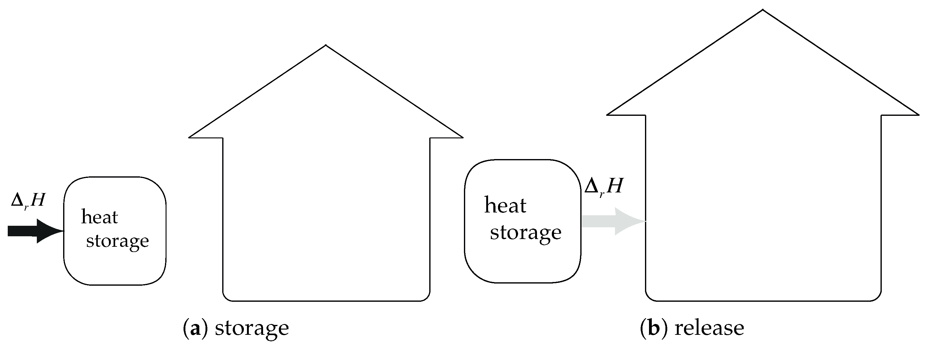
Figure 8.
System integration: heat of condensation is not recovered and heat of evaporation is not free: .
Figure 8.
System integration: heat of condensation is not recovered and heat of evaporation is not free: .

Figure 9.
System integration: heat of condensation is recovered and heat of evaporation is energy–free: .
Figure 9.
System integration: heat of condensation is recovered and heat of evaporation is energy–free: .

© 2020 by the authors. Licensee MDPI, Basel, Switzerland. This article is an open access article distributed under the terms and conditions of the Creative Commons Attribution (CC BY) license (http://creativecommons.org/licenses/by/4.0/).
Share and Cite
MDPI and ACS Style
Kuznik, F.; Johannes, K. Thermodynamic Efficiency of Water Vapor/Solid Chemical Sorption Heat Storage for Buildings: Theoretical Limits and Integration Considerations. Appl. Sci. 2020, 10, 489. https://doi.org/10.3390/app10020489
AMA Style
Kuznik F, Johannes K. Thermodynamic Efficiency of Water Vapor/Solid Chemical Sorption Heat Storage for Buildings: Theoretical Limits and Integration Considerations. Applied Sciences. 2020; 10(2):489. https://doi.org/10.3390/app10020489
Chicago/Turabian StyleKuznik, Frédéric, and Kévyn Johannes. 2020. "Thermodynamic Efficiency of Water Vapor/Solid Chemical Sorption Heat Storage for Buildings: Theoretical Limits and Integration Considerations" Applied Sciences 10, no. 2: 489. https://doi.org/10.3390/app10020489
Note that from the first issue of 2016, this journal uses article numbers instead of page numbers. See further details here.