A Review of Orbital Angular Momentum Vortex Beams Generation: From Traditional Methods to Metasurfaces


1
Department of Microwave Engineering, Harbin Institute of Technology, Harbin 150001, China
2
LEME, UPL, Univ Paris Nanterre, F92410 Ville d’Avray, France
*
Authors to whom correspondence should be addressed.
Appl. Sci. 2020, 10(3), 1015; https://doi.org/10.3390/app10031015
Submission received: 30 December 2019
/
Revised: 18 January 2020
/
Accepted: 30 January 2020
/
Published: 4 February 2020
(This article belongs to the Special Issue Advanced Active and Passive Metasurfaces)
Abstract
:In this paper, we review the generation of vortex beams carrying orbital angular momentum in the microwave domain. We firstly present the theory of Laguerre–Gaussian beams where it is demonstrated that they carry such type of momentum. We further provide an overview of the classical methods used to generate orbital angular momentum vortex beams, which rely on two main methods; plane wave to vortex wave conversion and direct generation using radiating antennas. Then, we present recent progress in the physics of metasurfaces devoted to the generation of vortex beams with a discussion about reflective and transmissive metasurfaces for plane wave to vortex wave conversion as well as methods to reduce the intrinsic divergence characteristics of vortex beams. Finally, we conclude on this rapidly developing research field.
1. Introduction
From Maxwell’s theory, it is well known that electromagnetic (EM) waves carry both linear momentum and angular momentum. The angular momentum is composed of two parts: spin angular momentum (SAM) corresponding to the polarization of the EM wave and orbital angular momentum (OAM) associated to the spatial distribution of the EM wave.
SAM of an EM wave has been recognized for a long time and it carries ± ħ per photon. However, OAM has only attracted valuable attention since 1992 when Allen et al. [1] showed that Laguerre–Gaussian (LG) beams possess an orbital angular momentum of lħ per photon, where l is an integer and refers to the topological charge (order) of the OAM mode, i.e., the number of phase twists around the vortex. In 1994, Allen et al. further discussed the relationship between non-paraxial beams and angular momentum since LG beams are not exact solutions of the full Maxwell’s theory that are only the solutions of the paraxial wave equation [2]. Under the condition of non-paraxial approximation, theoretical calculation results show that OAM still depends on the topological charge l. As long as the beams contain spiral phase, they will carry an OAM mode. It provides a simpler way to generate OAM, that is, vortex beams can be excited with a plane wave. While the phase of a plane wave is constant on the wavefront, the phase α of an OAM wave undergoes a linear variation along the angular coordinate with α = lφ. The field hence varies as e−jlφ.fl(r).e−jkz, where k is the wave vector, z is the propagation axis and fl(r) represents the field variation along the radial coordinate.
Early studies in optical regime concerning the interaction of OAM with matter raised applications in optical tweezers [3,4], optical drive of micro-machines [5], atoms trapping and guiding [6,7], microscopy [8], and photon entanglement [9]. In the radiofrequency (RF) domain, OAM has been firstly proposed to improve spectral efficiency in radio communications by creating multiple propagation sub-channels corresponding to the twisting degree of the EM wave [10,11,12,13,14]. Other possible applications of OAM include object identification [15] and radars [16,17,18,19,20].
It is common to generate OAM beams in the optical domain, especially when the programmable spatial light modulator (SLM) is available [21]. Existing optical devices can also provide mature schemes to manipulate OAM beams such as combination, splitting, collimation, concentration, and detection [22,23,24,25]. However, in RF and microwave domains, the wavelength is much longer than in optics, and therefore it is difficult to manipulate microwave OAM beams, such as beam combining and splitting, since coaxial transmission cannot be easily ensured. Therefore, for applications in microwave domain, the OAM wave generation method is very important to ensure optimal performances of the whole system. The main goals of this review work is to present an overview of the OAM beam generation through the use of metasurfaces. The paper is structured as follows: Section 1 presents a brief introduction on OAM and Section 2 focuses on Laguerre–Gaussian (LG) beams carrying OAM. In Section 3, we present the mostly used classical methods to generate vortex waves and Section 4 deals with the use of metasurfaces for OAM beam generation. Finally, Section 5 serves as a general conclusion.
2. Laguerre–Gaussian Beams Carrying OAM
In theory, any field in free space can be described by a continuous spectrum of cylindrical waves which is characterized by Laguerre polynomials [26]. Different expressions strictly satisfy the orthogonal relation. Beams propagating in the -z-direction in free space can be expressed as:
where u(r, φ, z) is the amplitude of beams in cylindrical coordinates, k is the wave number in free space. The space EM waves also satisfy the Helmholtz equation:
The substitution of Equation (1) into the scalar wave Equation (2) gives:
The electric field amplitude in the z-direction varies much slowly compared to the transverse field in the beam. Therefore, the paraxial wave equation is derived when the second derivative in the z-direction is ignored. Then, the cylindrically symmetric solutions Laguerre–Gaussian beams are given by [1]:
where w(z) is the radius of the beams, zR is the Rayleigh range. l and p are angular index and radial index, respectively. is the associated Laguerre polynomial, which is derived from:
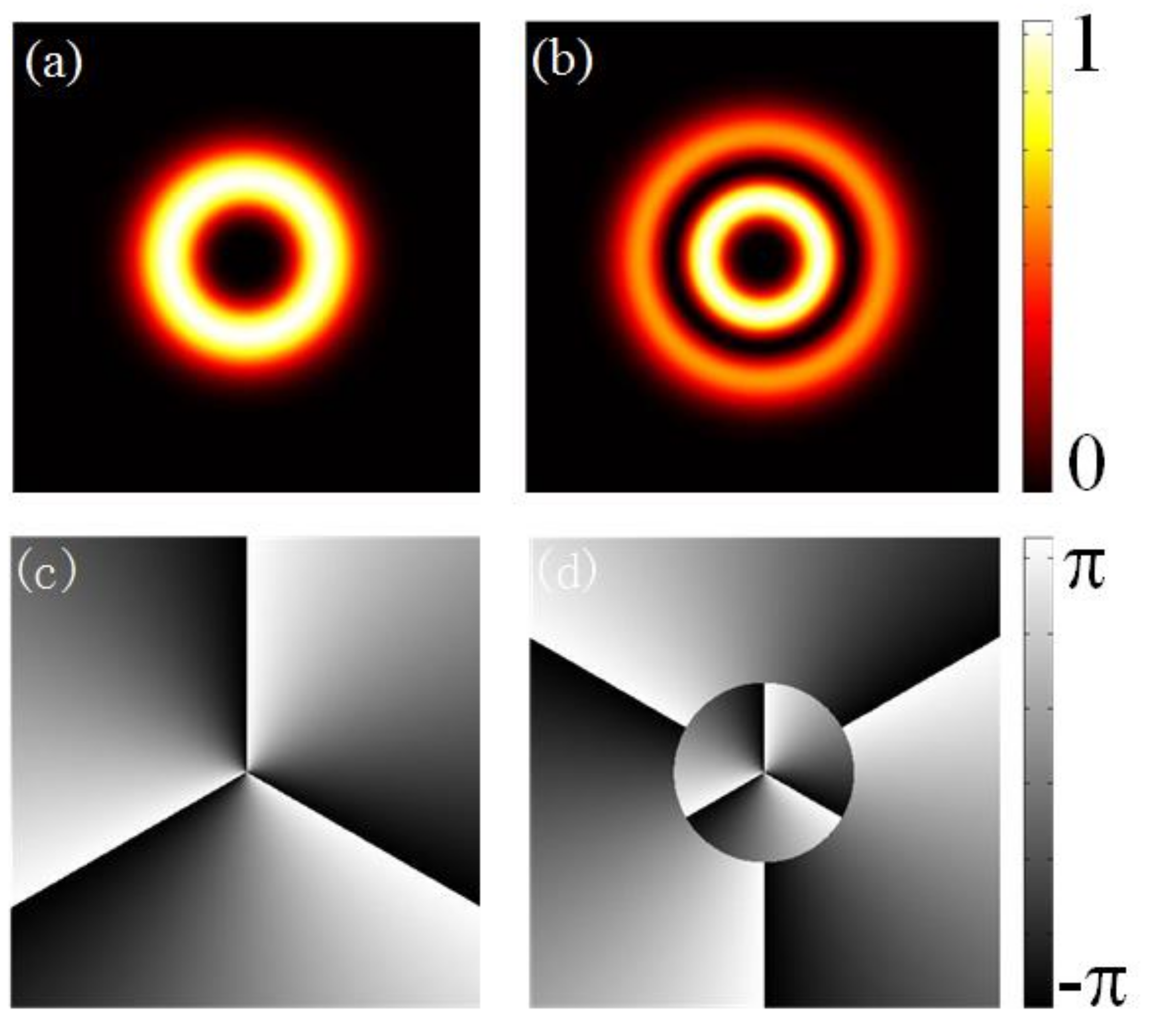
Different LG beams are determined by different number of l and p. All LG beams constitute a set of complete orthogonal basis vectors that can represent any spatial beams. The amplitude and phase distributions with different l and p values are shown in Figure 1. The radius of the ring-shaped beam will diffract when l increases, while the parameter p will lead to a change in the number of rings.
In 1992, Allen et al. pointed out that the LG beams have a well-defined orbital angular momentum where the spatial phase factor e−jlφ corresponds to the orbital angular momentum. The angular momentum density can be expressed as:
where ε0 is the permittivity, E and B represent the electric field and magnetic field, respectively. In classical mechanics and atomic physics, angular momentum can be decomposed into SAM and OAM. Therefore, the total angular momentum is:
where L represents OAM and S represents SAM. For a linear polarized wave, the time averaged angular momentum density is obtained when applied to LG beams expression:
The first two terms of the expression are symmetrical about the axis which are related to SAM. Therefore, the integration the angular momentum J will only remain the third term which is related to OAM. Similarly, for circularly polarized wave, the angular momentum power of z component is:
where σz = ± 1 for left handed and right handed circularly polarized (LHCP and RHCP) beams. As such, orbital angular momentum is theoretically demonstrated in the LG beams.
3. Classical Methods for Generating OAM Waves in RF Domain
The first RF OAM wave generation from microwave antennas was presented by Thidé et al. in 2007 [27]. Since then, the study of EM waves carrying OAM in the RF and microwave domains is constantly growing. Classically, in the radio domain, two main families of structures have been proposed to generate OAM waves. The first one consists in transforming a plane wave and can be achieved by using spiral phase plates [28,29], flat drilled phase plates [30,31], spiral [32] or twisted reflectors [11,33], and holography with a diffraction grating structure. In the second one, the OAM wave is directly generated using circular phased radiator arrays [10,34,35,36,37,38,39].
3.1. Spiral Phase Plate (SPP)
A spiral phase profile is obtained when a plane wave passes through a system of varying phase. Spiral phase plates (SPPs) come from the optical frequency region and are generally made of a material with constant refractive index and a radially varying thickness, as illustrated in Figure 2. Usually, the higher the topological charge is desired, the bigger is the thickness difference in the SPP. The advantages of SPP reside in small OAM beam divergence and low attenuation. The main disadvantages of the SPPs are that they are not operational for low-frequency signal transmission and since the design is fixed, they cannot provide simultaneous generation of several different OAM topological charges. The studies presented in References [28,29] have been performed in the millimeter wave frequency band at 86 and 60 GHz, respectively. Two different phase plates were designed in [28] and were made of polyethylene having a refractive index of 1.52 at millimeter-wave frequencies. One was utilized to generate the LG01 mode and the other one to generate the LG02 mode. The step heights of the phase plates were 6.7 mm and 13.4 mm respectively to give a single and a double wavelength step at 86 GHz. The main characteristic of a vortex OAM beam which is the null of energy at the center of the radiated beam (doughnut shaped radiation pattern) can be clearly observed in the results presented in Figure 2.
3.2. Flat Drilled Phase Plate
SPP can also be designed by drilling holes in a constant height dielectric bulk material in order to engineer the required spiral phase profile through effective permittivity tailoring. This kind of SPP can be referred as flat drilled phase plate. Such work has been realized at 32 GHz to generate OAM waves with topological charge l = −1 [30,31]. A horn antenna, commonly used in the microwave range for its high directivity and low sidelobes level, was used as the incident wave source to illuminate the phase plate, compared to a Gaussian beam generally used in optics.
3.3. Diffraction Grating
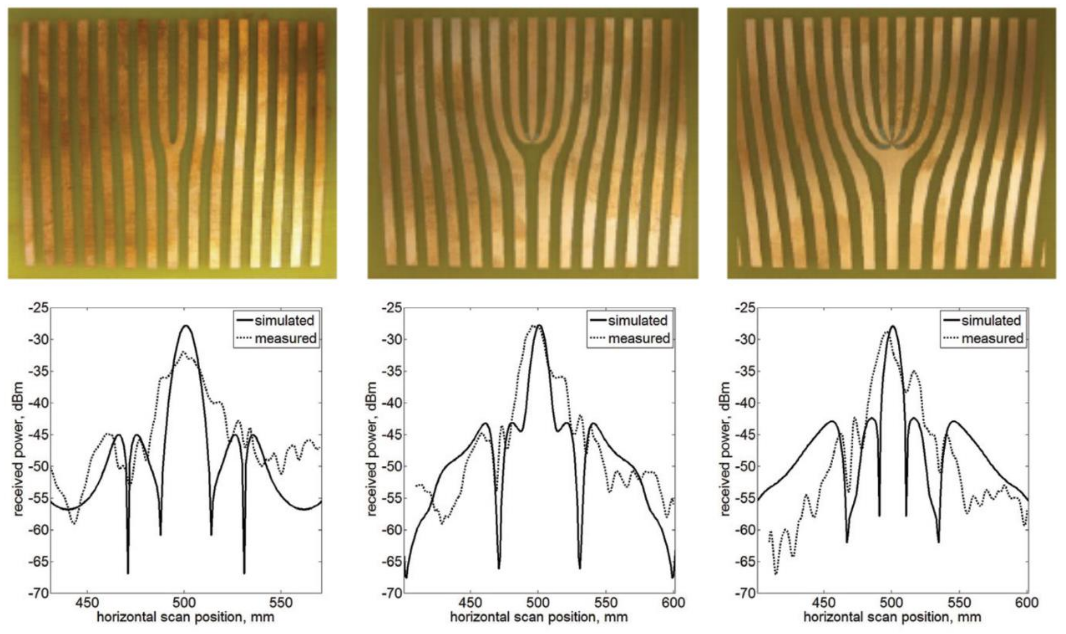
Diffraction grating is an optical structure composed of either parallel slits or parallel lines to operate in transmission or reflection mode, respectively. In OAM field, it is used as a hologram. When illuminated by a light beam, the structure diffracts the light into several beams in different directions and an interference pattern (hologram) is obtained by the interference between the incident and the diffracted beams. It is then possible to record the hologram between the two beams and then to use it to generate one beam from the other [40]. Such hologram has been applied in Ref. [29] to generate OAM vortex waves at 60 GHz (Figure 3) by illuminating the grating structure with a Gaussian beam transmitter.
The main elements of holographic masks are observable in the fork-grating dislocation (Figure 3), where the plane input wave is transformed through this zone. The shape and behavior of fork-grating is controlled by the topological charge l. Conversely to the spiral phase plate or flat drilled phase plate, and by observing the patterns in Figure 3, the hologram not only produces OAM vortex waves but also a Gaussian beam at boresight (0°) due to the illuminating wave. The output signal carries OAM on the sides of the centered Gaussian beam.
3.4. Spiral and Twisted Reflectors
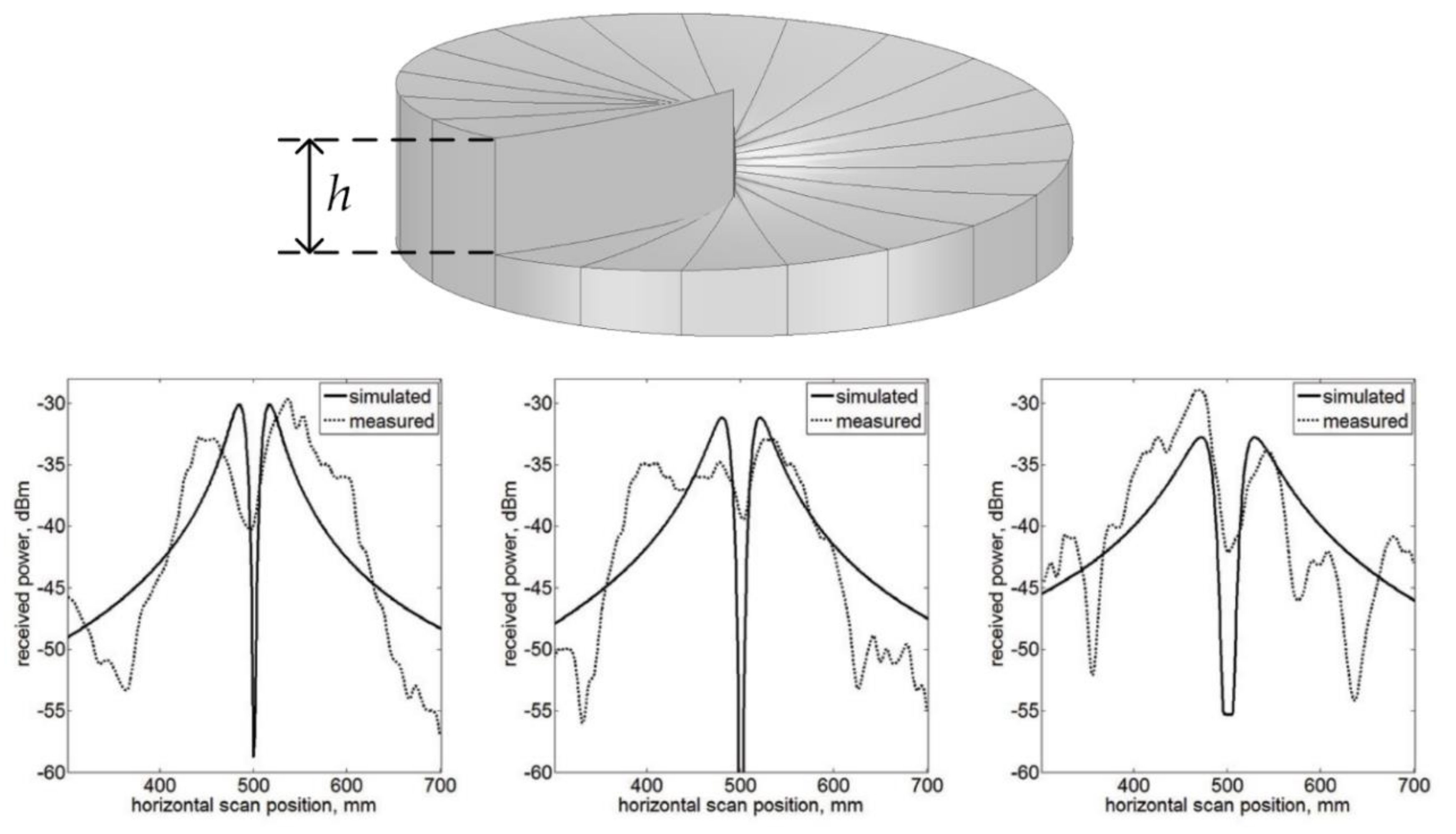
The spiral reflector proposed in [32] was made from styrofoam blocks, covered with an electrically conductive and reflective surface and was illuminated by a seven-element Yagi-Uda antenna intended for 2.4–2.5 GHz wireless local area network (WLAN) communications (Figure 4). The radio beam is reflected off the discrete eight-step staircase phase mask representing a discrete approximation of a non-focusing spiral reflector designed for a total 2π phase shift spiral.
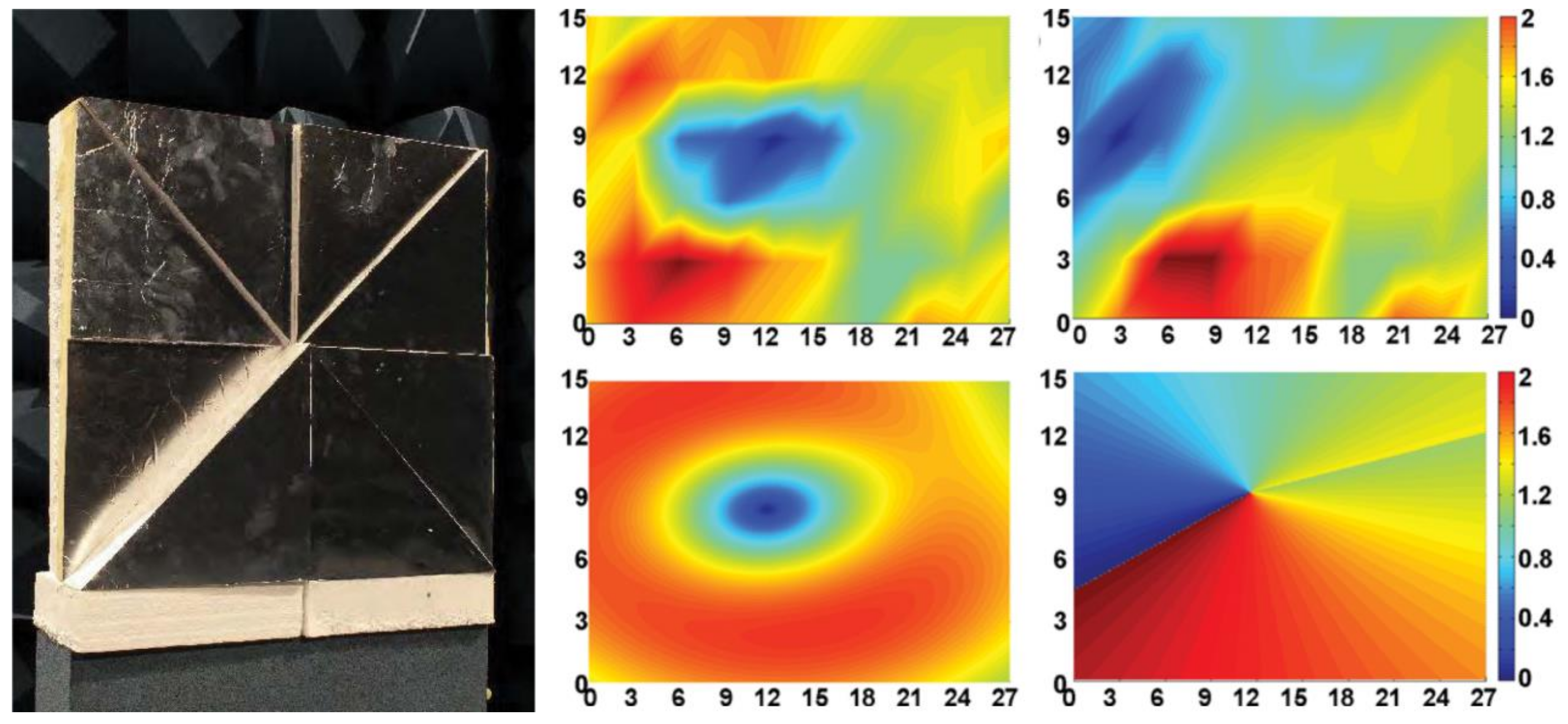
In [11,33], a helicoidal parabolic (twisted reflector) antenna was used to generate a vortex wave with a feeding source located at the focal point (Figure 5). The twisted reflector converts the field generated by the feeding source into a helical beam with a topological charge l that depends on the height of the step of the twisted reflector.
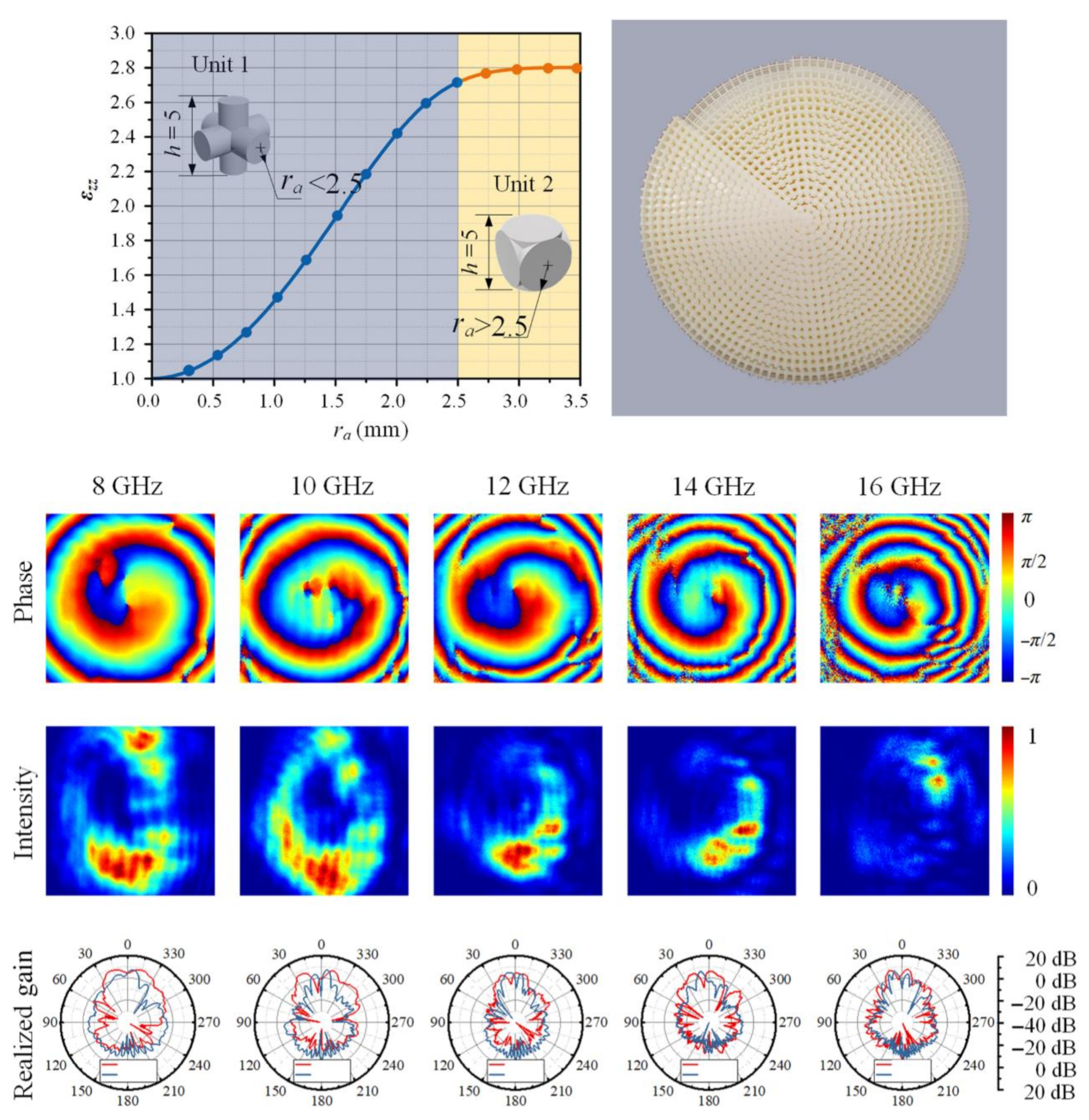
Such helicoidal parabolic reflector was recently flattened by the use of the transformation optics (TO) mathematical concept [41,42] and metamaterial structures. In [43,44], a spatial TO-based OAM generation method was proposed to design a flattened perfect electric conductor (PEC) backed three-dimensional (3D) printed cylindrically shaped dielectric structure so as to mimic a twisted reflector (Figure 6). The TO-based generation method allows to transform a certain zone above the helicoidal parabolic antenna into an oblate cylindrical space. This transformation led to a medium characterized by a permittivity distribution varying from 1 to 2.8, allowing a 3D printing of the device. By transmitting through the calculated oblate cylindrical space, a plane wave emitted from the feeding source is transformed into a vortex beam after its reflection from the grounded planar surface rather than from the helicoidal parabolic reflector. The all-dielectric OAM generation device is capable of maintaining performance over a broad frequency range since all-dielectric non-resonant materials are used in the design, as illustrated in Figure 6.
3.5. Circular Phased Arrays
The last approach concerns the direct generation of OAM beams through the application of uniform circular arrays (UCA) of radiating elements with a particular feeding system that allows specifying the required phase shift for each radiator corresponding to the generation of the selected OAM state. The number of radiators in the array has an additional influence on the OAM antenna, since it determines the largest OAM mode that can be generated. In 2007, Thidé et al. numerically designed the first microwave OAM radiator using a circular distributed radiator array [27]. UCA allows generating several different OAM modes by changing the phase shift from the feeding system and to shift the OAM state without changing the antenna configuration. However, the main disadvantage of UCA is the high divergence feeding system complexity. Later, other works have been presented on the generation of OAM vortex waves based on UCA [34,35,36,37,38,39]. In [34], instead of feeding all the radiators at the same time with a particular phase-shift between the elements, the radiators are fed sequentially with the same amplitude and phase. The first experimental results on UCA were presented in [36], where eight radiators were used in the array to generate mode l = −1 (Figure 7). Other types of radiating elements have been further used in the circular arrays, such as horn antennas [38] and single-arm spiral antennas [39].
Since the vortex beam diverges rapidly along propagation direction, different solutions have been proposed to reduce the divergence angle and increase the gain. For instance, a Fabry–Perot cavity in which a highly-reflective surface served as the superstrate, was numerically evaluated to generate a high gain vortex wave [45]. Afterwards, electromagnetic band-gap (EBG) superstrate was used to achieve high gain OAM vortex waves [46]. Lenses based on the use of metasurfaces [47,48] and all-dielectric materials [49,50] have further been applied to reduce beam divergence of OAM vortex waves generated by phased antenna arrays.
4. Metasurfaces for OAM Beam Generation
The conventional methods to generate vortex beams in microwave region have been discussed in the previous section. In the case of the circular phased array antennas, a complex feeding system should be implemented to accomplish spiral phase distribution with consistent power delivery. Besides, it needs more antenna elements when the number of OAM modes increases which will lead to a feed network more complex in the design process. Phase plates and reflectors are bulky structures that are usually not suitable for implementation in modern communications systems. Recently, metasurfaces (MS) have drawn much attention due to the unique ability of arbitrary wavefront control, such as amplitude, phase and polarization state of EM waves. Compared to metamaterials, metasurfaces are two-dimensional surface arrays with the advantages of low profile, light weight and ease of fabrication. For OAM generation, we classify metasurfaces into two main categories: reflective and transmissive. For reflective MS, amplitude attenuation is generally negligible and only a single layer of structure is generally required to achieve the coverage of the spiral phase. In contrast, transmissive MS for OAM generation are in most cases composed of several layers to achieve the required 2π phase shift needed for plane wave to vortex wave conversion and attention has to be paid to losses in the multi-layer structure.
4.1. Reflective Metasurfaces
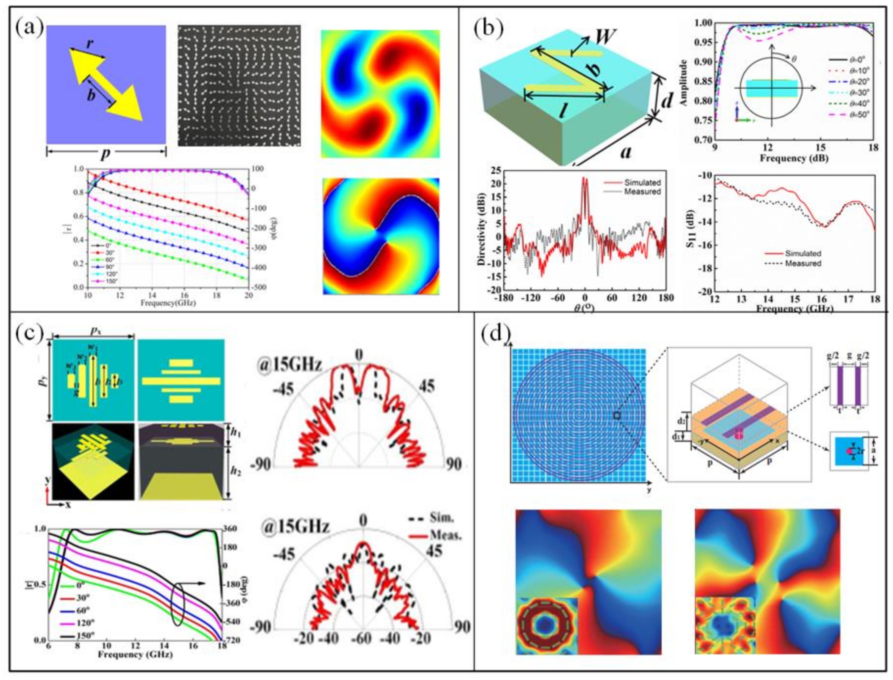
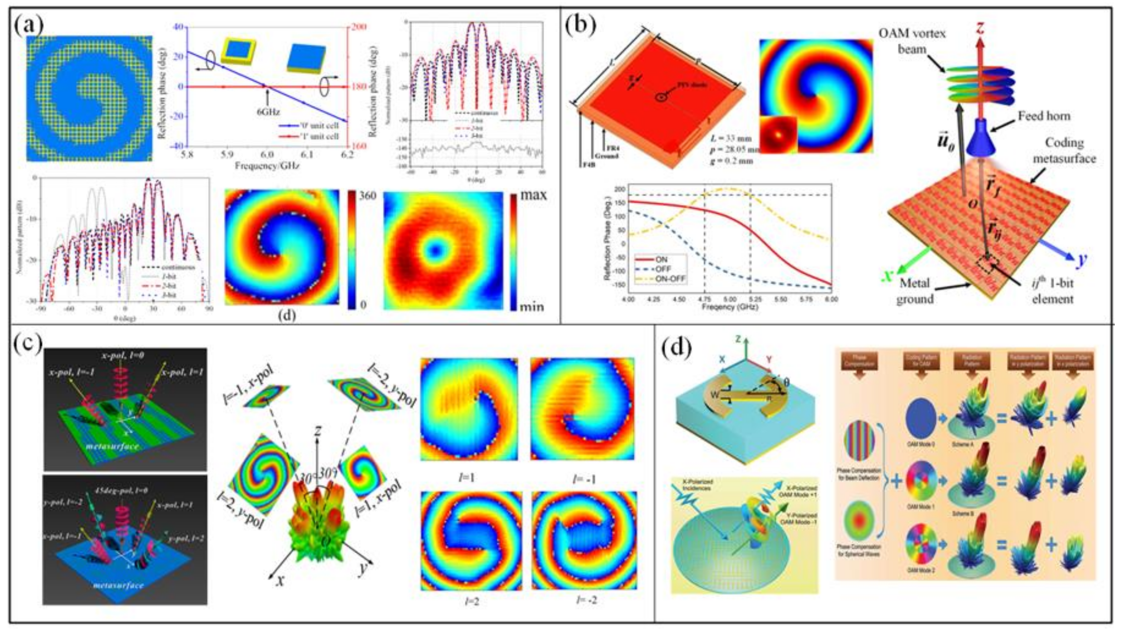
In Reference [51], a propagation phase reflective metasurface is designed to effectively generate single vortex beam with orbital angular momentum in the radiofrequency domain, as shown in Figure 8a. The unit cell consists of three patch dipoles. By controlling the length of the three patches and the distance between them, the reflected wave has a continuous reflection phase range of more than 2π. Based on the proposed unit cell, a reflective metasurface with 20 × 20 elements is designed to generate vortex beam carrying an OAM mode with topological charge l = 2 at 5.8 GHz. A metasurface composed of ring-surrounded bowtie patch resonators is proposed in [52]. The structure is inspired by the bowtie antenna which has wideband characteristics (Figure 8b). A linear phase variation is obtained when varying the radius of the bowtie patch under TM wave incidence. Several metasurfaces have been designed to generate OAM modes with l = 0, 1, 2 over about 3 GHz bandwidth. Single layer resonant structures are easy to fabricate, but the phase varies drastically at the resonant frequency, resulting usually in a narrow bandwidth.
In Reference [53], double-layered elements are used to design MS for the generation of broadband vortex beams. The unit cell is composed of two square patches separated by a dielectric substrate instead of only one patch in a single layer structure, as illustrated in Figure 8c. For one patch element, a strong magnetic resonance occurs between the patch and ground plane of the reflective MS, while for double-layered element, the magnetic resonance is due to the interaction between the two patches and the ground plane for low frequency and to the interaction between mainly the two patches for high frequency. Therefore, the phase response is more flat and the operational bandwidth is enhanced. The proposed metasurface generates vortex beams carrying an OAM mode l = 1 in the 8.5 GHz–11.5 GHz frequency range. Due to limitation of unit cell topology, the metasurface in [51] and [52] can only operate under single polarized incident waves. By properly designing the elementary cell pattern (Figure 8d), a polarization-insensitive OAM metasurface is proposed in [54]. Two concentric rings guarantee structural symmetry when introducing enough phase-shift range. The spiral phase distribution is realized by changing the radius of the inner and outer rings. A reflectarray-type prototype with l = 1 is fabricated to demonstrate the design at 5.8 GHz.
The phase shift of the metasurfaces in [51,52,53,54] can be controlled not only through varying structure parameters to introduce propagation phase, but also through rotation of the orientation of the meta-atom to introduce geometric phase. Compared to propagation phase, geometric phase which is usually called Pancharatnam–Berry (PB) phase is easier to implement. When the unit cell is rotated, the emitted phase of the cross-polarized component will have a phase shift as twice as the rotated angle under circular polarized (CP) incident wave. Therefore, only single-sized unit cell is needed which has the ability to convert CP wave to its cross polarization rather than a plurality of different-sized unit cells [55,56,57,58,59]. Besides, the unit cells with different rotation angles have the same dispersion characteristics and hence, the bandwidth of the vortex beams are usually broad. In Reference [55], an ultra-broadband reflective metasurface based on PB phase to generate vortex beams is proposed. A double arrow-shaped metallic layer is applied to achieve perfect CP wave conversion (Figure 9a). The metasurface presents an efficiency of 75.76% to excite vortex beams with OAM mode l = 2 in the 12 GHz–18 GHz frequency range. The N-shaped resonator based on PB phase is employed to achieve nearly 100% conversion efficiency in Reference [56]. The unit cell is suitable for broadband design which transmits 98% energy of incident CP wave to its cross-polarized wave (Figure 9b). Besides, when the incident angle varies from 0° to 50°, the conversion efficiency is higher than 90% in 8 GHz frequency bandwidth. The metasurface generates vortex beams with OAM mode l = 1 from 12 GHz to 18 GHz. Similarly, the polarization conversion bandwidth can also be expanded with a double layer unit cell.
A dual-layer meta-atom that can manipulate phase shift independently for x- and y-polarized waves is proposed in Reference [57]. The unit cell consists of five symmetric parallel dipoles with different parameters in each layer, as shown in Figure 9c. The reflection phase can be controlled independently without much crosstalk by arranging the dual-layer orthogonally. It is much easy to achieve CP wave polarization conversion over large bandwidth. The bandwidth of the metasurface generating vortex beams with OAM mode l = 1 ranges from 6.95 GHz to 18 GHz. A perfect electric conductor-perfect magnetic conductor (PEC-PMC) anisotropic metasurface for OAM generation is proposed in Reference [60] and is illustrated in Figure 9d. The top surface of the unit cell acts as a PEC surface which consists of two metal strips behaving like a parallel-plate waveguide. The x-polarized wave is totally reflected with an offset phase of π, while the y-polarized wave will transmit through it. The bottom surface acts as a PMC surface which is realized by the mushroom-like high-impedance surface. It reflects the y-polarized wave with zero phase shift. In this way, the unit can realize the perfect polarization conversion of CP wave. Two types of metasurface carrying an OAM mode l = 2, consisting of azimuthally continuous loops and azimuthally discontinuous loops, are designed based on the proposed unit cell. It can be observed that the continuous one shows smoother phase distribution than the discontinuous one.
A series of unit cells with continuous phase shift constitutes some difficulties in the design process. Though the introduction of PB phase can simplify the design, it can only operate under CP wave. Recently, digital metamaterials have been presented to create a new connection between the physical structure and digital information. The beams can carry specific information with only a few unit cells by digital coding. When the concept comes to the two-dimensional metasurface, the coding can be implemented by the reflected or transmitted phase and amplitude of the unit cells. The simplest one-bit code can be realized by the reflection phases 0° and 180°. A one-bit coding metasurface was proposed to generate vortex beams in Reference [61]. The elementary cell is composed of a metallic patch and a metallic ground plane printed on the two faces of a dielectric substrate. The reflection phase of two unit cells are 0° and 180°, respectively. The reduction of the coding number does not influence the divergence angle of main lobe, but the existence of quantization error will raise the side lobes. Besides, the one-bit quantization method does not have enough resolution to generate the vortex beam without any additional compensation in the normal direction for plane wave incidence. However, if other phase profiles, such as the spherical wave phase, are introduced into the vortex beam, then the quantization error will show pseudo-random distribution. Such a coding metasurface with OAM mode l = 1 was fabricated to demonstrate the effectiveness of the concept at 6 GHz and is shown in Figure 10a.
A tunable metasurface generating vortex beams with any OAM modes is proposed in Reference [62]. A positive intrinsic negative (PIN) diode is utilized as a switch between the two rectangular patches constituting the unit cell of the metasurface, as presented in Figure 10b. The two states “0” and “1” are realized by switching the PIN diode, controlled by direct current (DC) voltage, to ON and OFF states. Therefore, any OAM mode can be realized by switching the states of each unit cells judiciously on the metasurface. In Reference [63], a multiple OAM vortex beams is generated by one-bit coding metasurface. Combining the phase distribution of vortex beam with the phase distribution required for beam steering functionality, the incident energy can be redirected into desired directions. Due to the periodic variation of the phase, 0° phase is also regarded as 2π phase. In other words, the variation of phase from 0 to π also means variation of phase from 2π to π. Therefore, for one-bit coding beam steering, a vortex beam will reflect into two opposite directions under normally incident plane wave. The cross-dipole structure is utilized to manipulate x-polarized and y-polarized wave, respectively (Figure 10c). Then, by combining the coding of two orthogonal directions, the incident waves are simultaneously converted to vortex beams with l = ±1 and l = ±2 in different directions at 8.5 GHz. Another method to design coding OAM metasurface based on polarization bit was proposed in Reference [64]. The unit cell can cover 2π reflection phase for linearly polarized waves by adjusting each parameter (Figure 10d). Besides, when rotating the structure by ±45°, the polarization state of the reflected wave is converted to its cross-polarized component. The metasurface is divided into two regions: inner region and outer region. Each region determines whether to convert the polarizations of incident beam or not and modulate the OAM modes into the reflected beam. Under illuminating x-polarized wave, two vortex beams carrying OAM modes l = 1 and l = 2 in the x- and y- polarized component can be clearly observed at 15 GHz, respectively.
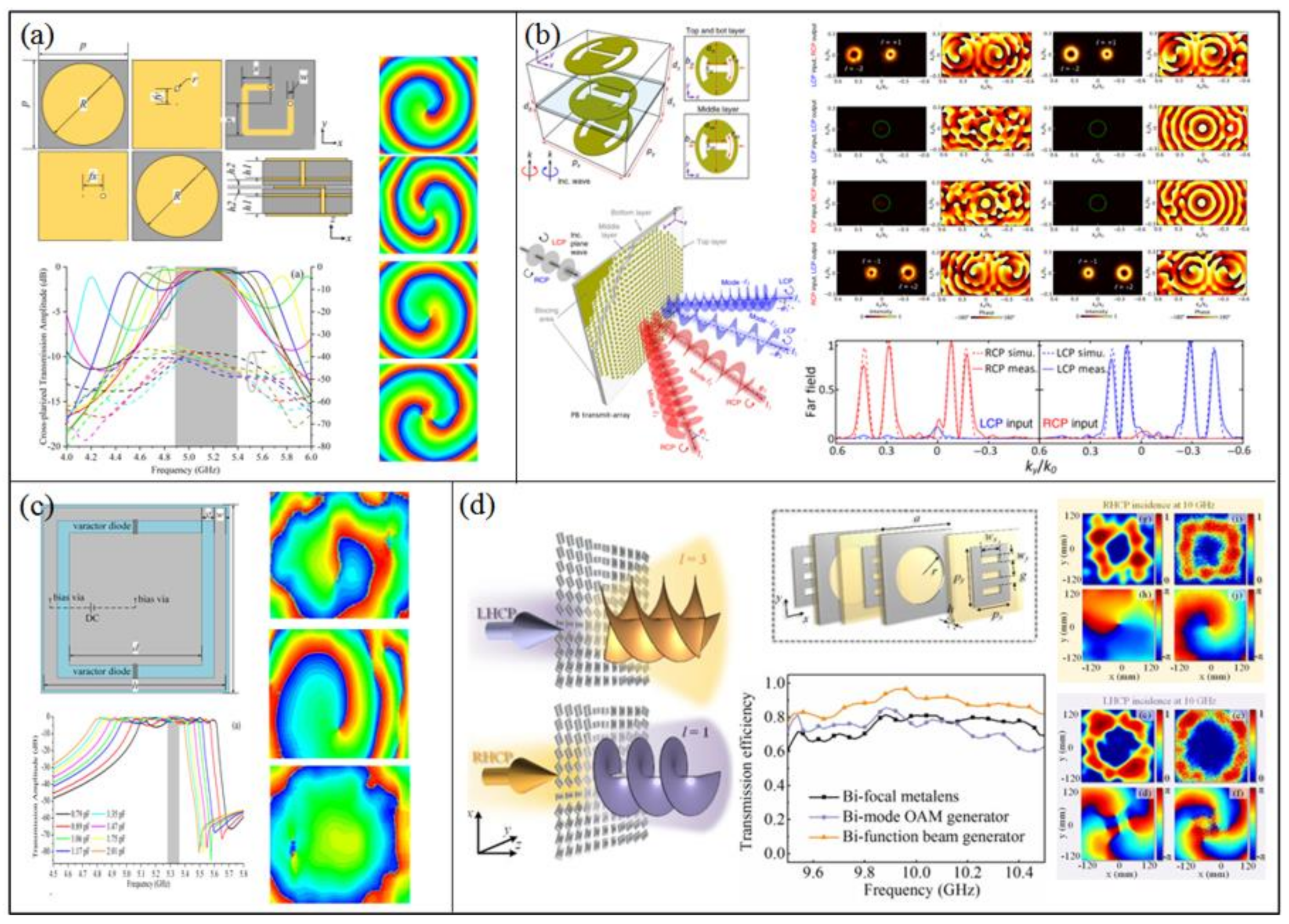
To enhance the information capacity of a metasurface, a single linear polarization reflective metasurface generating multiple vortex beams with different OAM modes in different directions was proposed in Reference [65]. The unit cell consists of only one patch element, as shown in Figure 11a. The reflected phase has a continuous change when the length of patch is increased or decreased. When vortex beams with different OAM modes are excited in the same direction, the mode order will be the sum of them. Therefore, different vortex beams can only be generated in different directions. Besides, interference may occur if the beams are close to each other. By compensating the phase of different OAM modes and diffraction direction, the metasurface generates two vortex beams with l = 2 in opposite propagation directions (θ = ±30°). The operational frequency range of the metasurface spans from 5.5 GHz to 6.5 GHz.
Another way to expand the channel capacity is to control the polarization of wave freely. For linear polarized wave, it can be easily realized by a unit cell that can control phase shift for x- and y-polarized waves independently. However, for CP wave, it is hard to control LHCP and RHCP independently when only geometric phase is utilized because they are constrained to be conjugate values in the electric field form. In other words, vortex beams will have opposite mode number for LHCP and RHCP. To overcome the limitation, a metasurface merges propagation phase and geometric phase together in Reference [66]. It can be demonstrated that the analytical solutions for reflective dual-helicity decoupled wavefront control contains the x-polarized reflection phase ϕx, the y-polarized reflection phase ϕy, and the rotation angle α. Besides, ϕx and ϕy have a phase difference of π. The unit cell consists of dual-layer cross dipole and a ground plane (Figure 11b). In order to simplify the design, the unit cells are transformed into digital coding cells. The phase coverage is discretized by 45° gradient into 64 unit cells for two CP waves and each polarization has eight states. A complex coding distribution was realized according to the demand. The metasurface generating the vortex beam with OAM mode l = 1 in xoz plane under LHCP wave and two pencil beams in the yoz plane for RHCP wave at 16 GHz was fabricated to demonstrate the theory. In Reference [67], independent control of polarizations, beam numbers, OAM modes and orientations were proposed by phase compensation. The unit cell is composed of two orthogonal I-shaped dipoles able to control the phase shift of x- and y-polarized waves independently. To verify the proposed approach, a metasurface generating triple vortex beams was designed; one has the mode l = −1 for the linear polarized (LP) wave and mode l = +1 for the RHCP and LHCP waves (Figure 11c).
A decoupled method for CP wave is proposed in Reference [68] which excites vortex beams under single CP wave. The unit cell consists of two split ring resonators (SRRs) which are twisted to each other by 45°, as shown in Figure 11d. Both SRRs can introduce PB phase with 100% efficiency under illuminating CP wave. Moreover, they exhibit symmetric and asymmetric modes parallel and perpendicular to the symmetry axis. According to Jones matrix, the in-phase constructive interference for co-polarized CP wave and out-of-phase destructive interference for cross-polarized CP wave are realized when the phase difference between two CP waves is Δϕ = −90° and the twist angle of two SRRs is 45°. A metasurface able to generate two RHCP vortex beams at 9.5 GHz and four LHCP vortex beams at 10.5 GHz was designed.
4.2. Transmissive Metasurfaces
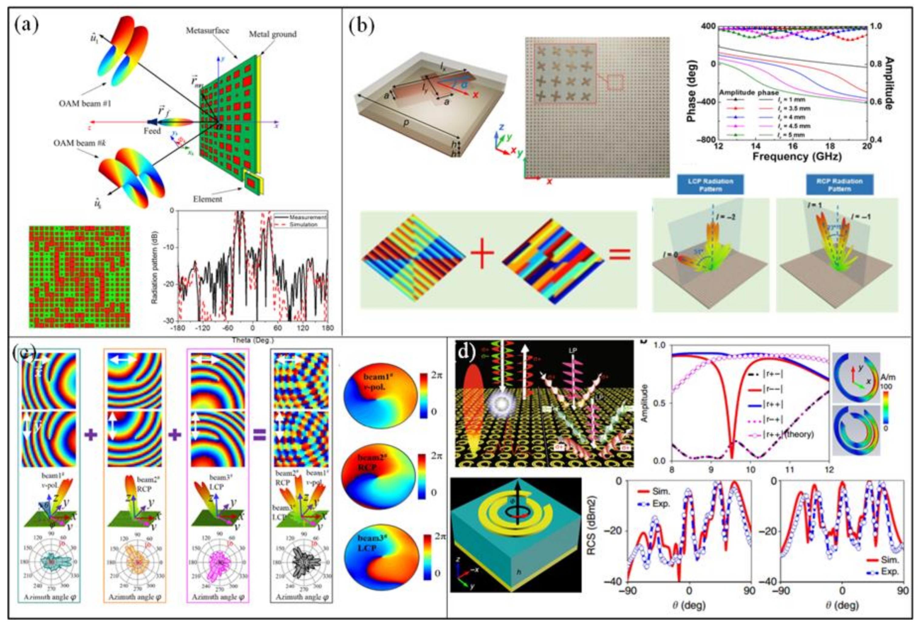
For transmissive OAM metasurfaces, generation efficiency needs to be considered since there is no ground plane to reflect all energy. It has been demonstrated that only 25% efficiency can be achieved in a single layer structure due to no excitation of magnetic resonance [69,70]. The design of a high efficiency transmissive metasurface is therefore a challenging problem that merits to be considered. A unit cell consisting of a cylindrical dielectric resonator and a metallic rod to manipulate the EM wavefront was proposed in Reference [71]. The metallic rod provides the necessary broadband electric polarization, and the cylindrical dielectric resonator provides the necessary broadband magnetic polarization. By tuning the unit parameters, 2π phase shift can be covered with high transmission magnitude. According to the concept of gradient phase discontinuity, a vortex beam carrying an OAM mode l = 1 can be generated by the flat spiral gradient phase with high efficiency at in the 8 GHz–9.8 GHz frequency band. However, to have strong electric and magnetic resonances, the length of the cylindrical rod must not be too short. The overall thickness of the metasurface is 10 mm (0.3λ0).
Miniaturized element frequency selective surfaces (MEFSS) were proposed to generate high efficiency vortex beams in Reference [72]. The elementary cell is composed of four layers of patches and three layers of wire grids alternately separated by dielectric substrates (Figure 12a). The patches are considered as capacitors while the wire grids are considered as inductors. The cascading distance can be effectively reduced by the strong coupling of the two kind of components. By tuning the size of patches, eight unit cells can be obtained with a transmission phase gradient of 45° and nearly 100% efficiency at 10.6 GHz. Even though the amplitude is non-uniform, the efficiency of vortex beams with l = 1 exceeds 60% in the 10 GHz–11.3 GHz frequency band. The overall thickness is only 0.15λ0.
A subwavelength scatterer based on photon spin Hall effect (PSHE) to generate high efficiency OAM waves was proposed in Reference [73]. The proposed unit cell consists of two double-headed arrows printed on the top and bottom of the dielectric substrate (Figure 12b). By introducing the magnetic resonance, the unit cell can effectively convert CP wave to its cross-polarized component in transmission. The conversion efficiency attains 84.6% at 10 GHz. However, when the unit cell is rotated to introduce PB phase, the amplitude of cross-polarized component cannot be kept constant, resulting in a reduction of the efficiency of the vortex beams excitation. The metasurface generating vortex beams with l = 2 presents an efficiency of 45% with a thickness of 0.05λ0. In Ref. [74], a unit cell consisting of complementary split ring resonators (CSRRs) for full phase control in a 0.8 mm (0.05λ0) thick metasurface was presented (Figure 12c). The proposed unit cell transmits a circularly polarized wave to its cross-polarized component with a high efficiency of 81%. The calculated conversion efficiency of OAM beams with l = 1 in the transmitted wave is up to 81.8% while the total transmission efficiency is only 15.2% and it becomes lower for higher modes. This is mainly due to the fact that compared to the whole metasurface, the scatterers are too few to satisfy the periodicity along x- and y-directions.
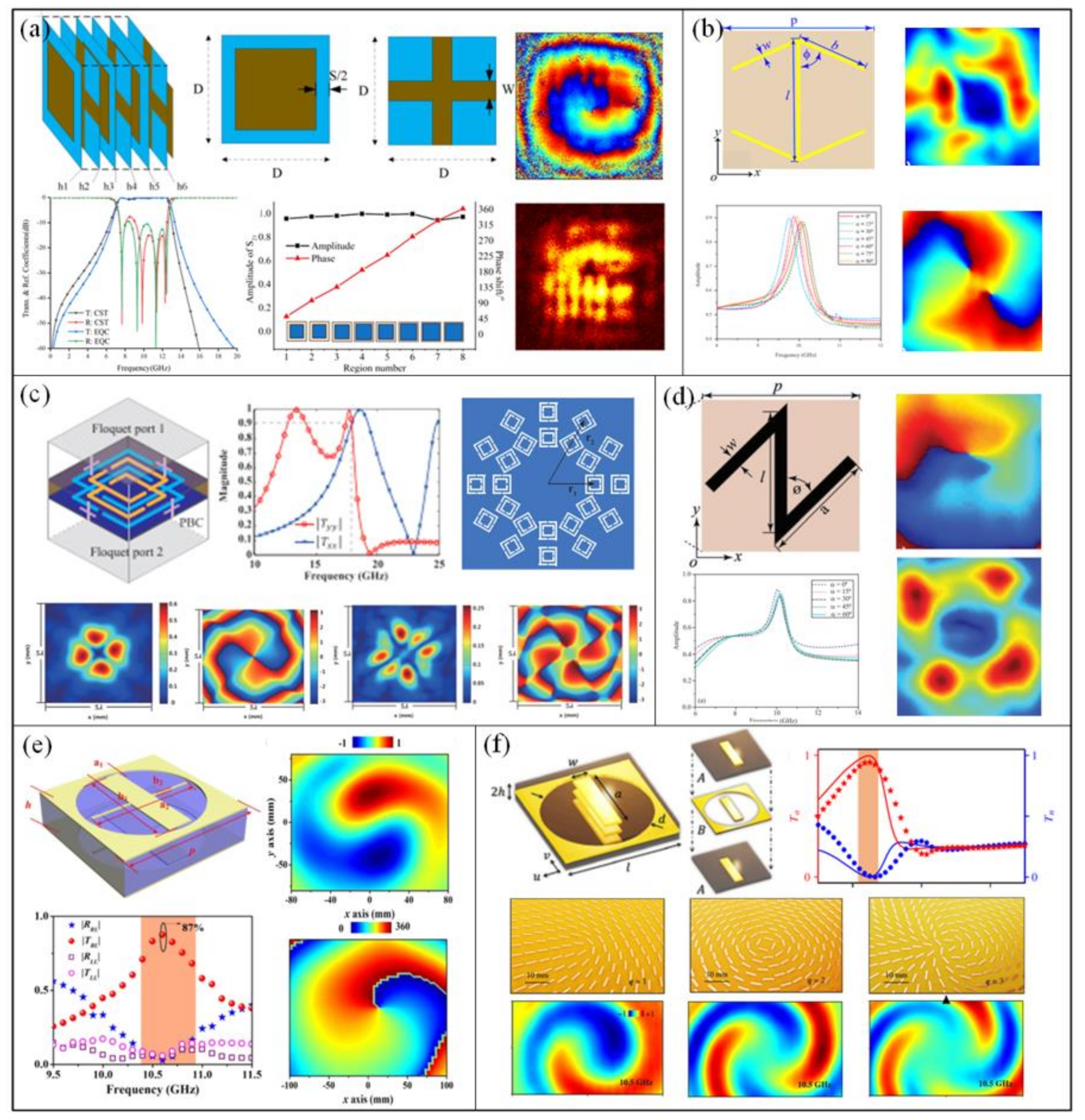
In Reference [75], the efficiency was enhanced by dual-layer Z-shaped metallic patterns shown in Figure 12d. The unit cell has nearly the same polarization conversion efficiency as two double-headed arrow unit, but the amplitude is more stable when it is rotated. A transmission efficiency of 55% is achieved for the same OAM mode l = 2. An ultrathin unit cell was proposed in Reference [76] to generate high efficiency vortex beams. The unit consists of a cross-bar structure with positive permittivity and holey metallic ring resonator with negative permittivity on both sides of a dielectric substrate (Figure 12e). The transmission amplitude and phase can be controlled independently by the length of the cross bar. When the transmission phase in the two orthogonal directions has a phase difference of π, 95% conversion efficiency of the cross-polarized component can be obtained at 10.6 GHz. The maximum excitation efficiency reaches 87% for OAM mode l = 1 and the overall thickness of the metasurface is only 0.07λ0. A nearly 100% efficiency photonic spin hall effect (PSHE) PB meta-atom named as ABA structure, with A and B representing two metal layers, was proposed in Reference [70]. The unit cell is composed of three metallic layers. Layer A is realized by an anisotropic resonator of rectangular patch while Layer B is realized by a holey metallic film coupled with a metallic bar (Figure 12f). The conversion efficiency could reach 91% at 10.5 GHz. Three vortex beam carrying OAM modes 1, 2, 3 were constructed by the ABA units in different metasurfaces of thickness 0.125λ0, respectively.
The polarization state of EM wave can be set as a convenient switch to alter the different output wavefronts generated by bi-functional meta-devices. In Reference [77], the authors designed a multilayer unit cell that was inspired from the patch antenna (Figure 13a). The unit cell has five metallic layers and four dielectric layers. The top patch can couple the linear-polarized wave into the guided mode in the stripline structure, and the bottom patch decouples the guided wave into its cross-polarized component. Different transmission phase distributions are introduced by different length of the stripline with low transmission losses. Two metasurfaces of thickness 0.074λ0 with different OAM modes of 1 and 2 were designed through the transmission phase steps of 45° and 90°, respectively. Due to the asymmetry of the polarization conversion, the metasurfaces were able to excite two opposite modes simultaneously, +1 and +2 modes for x-polarized wave and −1 and −2 modes for y-polarized wave at 5.14 GHz. An active metasurface to separately generate vortex beams carrying different modes is proposed in Reference [78] (Figure 13c). The unit cell consists of a patch and a metallic loop. Two varactor diodes are placed in the gaps between them which is controlled by a DC bias voltage with a low transmission loss. When the reverse voltage bias varies from 0 V to 30 V, 2π phase coverage can be easily obtained. Three different orders of OAM modes l = +1, l = −1 and l = 0 are separately excited at 5.35 GHz. The efficiency of the three modes are about 45%.
In Reference [79], a multiplexed CP vortex beam generator is proposed by overlapping the phase masks of a harmonic spatial light modulator and spiral phase plates. The unit cell cascades three anisotropic impedance surfaces with custom-designed anisotropy to achieve high efficiency of circular polarization conversion, as shown in Figure 13b. A single vortex-beam PB transmitarray (l = 1) was designed which could bend the wave towards the direction of a particular diffraction mode with a high purity. The efficiency of the generated vortex beams was 88% at 29.4 GHz and over 50% in a non-narrow bandwidth of 17%. A dual vortex beam transmitarray was designed by incorporating spiral phase profiles into a harmonic-response spatial light modulator with tailored intensity. When the structure is illuminated by circularly polarized incident wave, two vortex beams with OAM modes l = 1 and l = −2 are excited in different diffraction directions. The dual OAM beams metasurface achieve 71% efficiency at 29.4 GHz and over 50% in a frequency bandwidth of 13%. In Reference [80], the authors proposed a mechanism for producing distinct OAM modes in orthogonal circular polarized (CP) transmitted fields, which breakthrough the inherent symmetric restriction between orthogonal CP waves (Figure 13d). The vortex beam carrying an OAM with mode l = 1 was generated in the cross-polarized output field under RHCP illumination, while the OAM with mode l = 3 is produced through cross-polarization under LHCP illumination. The polarization state of incident wave acts as the important role for altering the distinct OAM modes, and hence dual mode vortex beams have been generated conveniently and effectively.
4.3. Divergence Reduction of OAM Vortex Beams
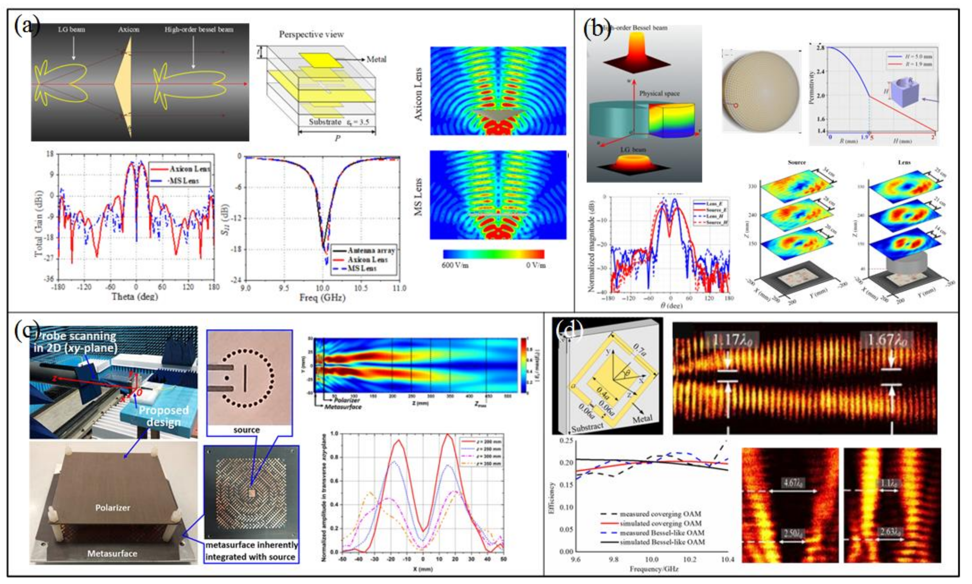
Vortex waves present divergence characteristics in propagation, which become worse when the OAM topological order increases and also when propagation distance increases. It might limit the practical applications of vortex beams for long distance communications or transmitting systems. A common solution is to converge the vortex beam. However, the limitation of this method is that it can only focus the beam to a point close to the metasurface rather than propagating over a long distance. In Reference [47], a flat metalens was proposed to collimate the vortex waves (Figure 14a). The converging lens system is excited by an OAM beam generator composed of a conventional circular patch antenna array source consisting of eight patches with the same phase shift between each of the neighboring elements. The metasurface is placed at a distance 2λ above the antenna source to compensate the phase of vortex beams. The divergence characteristics of vortex beams are obviously improved as they transmit through the metalens around 10 GHz frequency. Meanwhile, the propagation directivity and gain are also enhanced from 9 dBi to 15 dBi. The transmission efficiency is over 75% and reaches 88.14% at 10 GHz. Moreover, the purity of OAM mode l = 1 is degraded by only 1%. In Reference [50], a broadband all-dielectric 3D-printed cylindrical collimating lens was proposed to solve the divergence characteristics drawback of vortex beams (Figure 14b). The design comes from the transformation optics concept. By solving the transformation equations of Laguerre–Gaussian (LG) to high-order Bessel (HOB) beam, the permittivity distribution of the metamaterial medium is obtained. The equivalent permittivity was varied by considering air holes in a bulk dielectric medium. The permittivity decreases when the radius of the cylindrical cavity increases. The divergence angle and diameter of the vortex beams can be greatly reduced through the metamaterial medium. The frequency bandwidth was about 8 GHz around 10 GHz operating frequency thanks to the use of all-dielectric non-resonant unit cells.
The integration of the vortex beam excitation and the non-diffraction function can be realized by phase compensation. In Reference [81], a reflective metasurface was presented to generate a non-diffractive Bessel beam carrying OAM modes. The system consists of three parts; a circular cavity backed substrate-integrated waveguide (SIW) source, a polarizer, and the metasurface, as shown in Figure 14c. The metasurface converts the linear polarized incident wave to its cross-polarized component carrying non-diffraction vortex beams at 40.25 GHz. In Reference [82], the authors proposed a general scheme to optimize the divergence constraints of vortex beams (Figure 14d). Firstly, the converging phase distribution has been imposed into the vortex beam, which can effectively focus the OAM with required mode into preset plane, where the radius of converged vortex beam in focal plane can be decreased by nearly four times. This focused OAM can be effectively applied in communication systems, where the propagation distance is specifically fixed. On the other hand, the spatial phase profile of Bessel beam has been added into a vortex beam, which can produce quasi-non-diffractive OAM beam within a long propagation distance. It can be obviously seen that the combination with different functional wavefronts can effectively optimize the divergent property of traditional vortex beam, and realize OAM carrying new and useful properties.
5. Conclusions
In this paper, a review has been made on the generation of OAM vortex beams in the microwave domain. In a first step, we have presented the theory of Laguerre–Gaussian beams, where it is shown that they possess a well-defined orbital angular momentum. We have also reviewed the main classical methods used to generate such beams. They mainly include structures such as phase plates, reflectors and diffraction gratings for transforming plane waves to vortex waves and antenna arrays for direct radiation of electromagnetic waves carrying OAM. More recently, metasurfaces have revolutionized the way of tailoring electromagnetic properties and functionalities through the engineering of subwavelength elements. In this context, metasurfaces, whether they operate in a reflection or transmission manner, have been applied to transform plane waves to vortex waves carrying OAM. Moreover, functionalities such as Bessel beam profile and converging lens profile have been combined with OAM phase profile to be integrated in a single metasurface in order to reduce the intrinsic divergence characteristics of OAM beams.
In the view of the implementation of metasurfaces for the generation of vortex waves carrying orbital angular momentum, practical applications in the area of wireless communications can be considered. OAM metasurfaces can indeed offer simple and low-cost systems, along with high efficiency and other combined functionalities such as lensing. However, efforts towards integrated illuminating sources still need to be done.
Author Contributions
Conceptualization, K.Z. and S.N.B.; writing—original draft preparation, K.Z., Y.W., Y.Y. and S.N.B.; writing—review and editing, K.Z. and S.N.B.; supervision, K.Z. and S.N.B.; funding acquisition, K.Z. All authors have read and agreed to the published version of the manuscript.
Funding
National Natural Science Foundation of China (61771172, 61571155, 61401122).
Conflicts of Interest
The authors declare no conflicts of interest.
References
- Allen, L.; Beijersbergen, M.W.; Spreeuw, R.; Woerdman, J.P. Orbital angular momentum of light and the transformation of Laguerre-Gaussian laser modes. Phys. Rev. A 1992, 45, 8185. [Google Scholar] [CrossRef] [PubMed]
- Barnett, S.M.; Allen, L. Orbital angular momentum and nonparaxial light beams. Opt. Commun. 1994, 110, 670–678. [Google Scholar] [CrossRef]
- Curtis, J.E.; Grier, D.G. Structure of optical vortices. Phys. Rev. Lett. 2003, 90, 133901. [Google Scholar] [CrossRef] [PubMed] [Green Version]
- Gecevičius, M.; Drevinskas, R.; Beresna, M.; Kazansky, P.G. Single beam optical vortex tweezers with tunable orbital angular momentum. Appl. Phys. Lett. 2014, 104, 231110. [Google Scholar] [CrossRef]
- Knöner, G.; Parkin, S.; Nieminen, T.A.; Loke, V.L.; Heckenberg, N.R.; Rubinsztein-Dunlop, H. Integrated optomechanical microelements. Opt. Express 2007, 15, 5521–5530. [Google Scholar] [CrossRef] [PubMed]
- Kuga, T.; Torii, Y.; Shiokawa, N.; Hirano, T.; Shimizu, Y.; Sasada, H. Novel optical trap of atoms with a doughnut beam. Phys. Rev. Lett. 1997, 78, 4713. [Google Scholar] [CrossRef]
- Marzo, A.; Caleap, M.; Drinkwater, B.W. Acoustic virtual vortices with tunable orbital angular momentum for trapping of mie particles. Phys. Rev. Lett. 2018, 120, 044301. [Google Scholar] [CrossRef] [Green Version]
- Yan, L.; Gregg, P.; Karimi, E.; Rubano, A.; Marrucci, L.; Boyd, R.; Ramachandran, S. Q-plate enabled spectrally diverse orbital-angular-momentum conversion for stimulated emission depletion microscopy. Optica 2015, 2, 900–903. [Google Scholar] [CrossRef] [Green Version]
- Mair, A.; Vaziri, A.; Weihs, G.; Zeilinger, A. Entanglement of the orbital angular momentum states of photons. Nature 2001, 412, 313–316. [Google Scholar] [CrossRef] [Green Version]
- Mohammadi, S.M.; Daldorff, L.K.S.; Bergman, J.E.S.; Karlsson, R.L.; Thide, B.; Forozesh, K.; Carozzi, T.D.; Isham, B. Orbital angular momentum in radio—A system study. IEEE Trans. Antennas Propag. 2010, 58, 565–572. [Google Scholar] [CrossRef]
- Tamburini, F.; Mari, E.; Sponselli, A.; Thide, B.; Bianchini, A.; Romanato, F. Encoding many channels on the same frequency through radio vorticity: First experimental test. N. J. Phys. 2012, 14, 033001. [Google Scholar] [CrossRef]
- Wang, J.; Yang, J.Y.; Fazal, I.M.; Ahmed, N.; Yan, Y.; Huang, H.; Ren, Y.X.; Yue, Y.; Dolinar, S.; Tur, M.; et al. Terabit free-space data transmission employing orbital angular momentum multiplexing. Nat. Photonics 2012, 6, 488–496. [Google Scholar] [CrossRef]
- Yan, Y.; Xie, G.D.; Lavery, M.P.J.; Huang, H.; Ahmed, N.; Bao, C.J.; Ren, Y.X.; Cao, Y.W.; Li, L.; Zhao, Z.; et al. High-capacity millimetre-wave communications with orbital angular momentum multiplexing. Nat. Commun. 2014, 5, 4876. [Google Scholar] [CrossRef] [PubMed] [Green Version]
- Hui, X.N.; Zheng, S.L.; Chen, Y.L.; Hu, Y.P.; Jin, X.F.; Chi, H.; Zhang, X.M. Multiplexed millimeter wave communication with dual orbital angular momentum (OAM) mode antennas. Sci. Rep. 2015, 5, 10148. [Google Scholar] [CrossRef] [Green Version]
- Uribe-Patarroyo, N.; Fraine, A.; Simon, D.S.; Minaeva, O.; Sergienko, A.V. Object identification using correlated orbital angular momentum states. Phys. Rev. Lett. 2013, 110, 043601. [Google Scholar] [CrossRef]
- Liu, K.; Cheng, Y.; Yang, Z.; Wang, H.; Qin, Y.; Li, X. Orbital-angular-momentum-based electromagnetic vortex imaging. IEEE Antennas Wirel. Propag. Lett. 2014, 14, 711–714. [Google Scholar] [CrossRef]
- Lin, M.T.; Gao, Y.; Liu, P.G.; Liu, J.B. Improved OAM-based radar targets detection using uniform concentric circular arrays. Int. J. Antennas Propag. 2016, 2016, 1852659. [Google Scholar] [CrossRef] [Green Version]
- Lin, M.T.; Gao, Y.; Liu, P.G.; Liu, J.B. Super-resolution orbital angular momentum based radar targets detection. Electron. Lett. 2016, 52, 1168. [Google Scholar] [CrossRef]
- Bu, X.X.; Zhang, Z.; Chen, L.Y.; Liang, X.D.; Tang, H.B.; Wang, X.M. Implementation of vortex electromagnetic waves high-resolution synthetic aperture radar imaging. IEEE Antennas Wirel. Propag. Lett. 2018, 17, 764–767. [Google Scholar] [CrossRef]
- Bu, X.X.; Zhang, Z.; Liang, X.D.; Chen, L.Y.; Tang, H.B.; Zeng, Z.; Wang, J. A novel scheme for MIMO-SAR systems using rotational orbital angular momentum. Sensors 2018, 18, 3511. [Google Scholar] [CrossRef] [Green Version]
- Cai, X.L.; Wang, J.W.; Strain, M.J.; Johnson-Morris, B.; Zhu, J.B.; Sorel, M.; O’Brien, J.L.; Thompson, M.G.; Yu, S.T. Integrated compact optical vortex beam emitters. Science 2012, 338, 363–366. [Google Scholar] [CrossRef]
- Coomber, S.; Cameron, C.; Hughes, J.; Sheerin, D.; Slinger, C.; Smith, M.A.G.; Stanley, M. Optically addressed spatial light modulators for replaying computer generated holograms. Spat. Light Modul. Technol. Appl. 2001, 4457, 9–19. [Google Scholar]
- Genevet, P.; Lin, J.; Kats, M.A.; Capasso, F. Holographic detection of the orbital angular momentum of light with plasmonic photodiodes. Nat. Commun. 2012, 3, 1278. [Google Scholar] [CrossRef] [PubMed] [Green Version]
- Liu, A.P.; Xiong, X.; Ren, X.F.; Cai, Y.J.; Rui, G.H.; Zhan, Q.W.; Guo, G.C.; Guo, G.P. Detecting orbital angular momentum through division-of-amplitude interference with a circular plasmonic lens. Sci. Rep. 2013, 3, 2402. [Google Scholar] [CrossRef] [PubMed] [Green Version]
- Rui, G.H.; Abeysinghe, D.C.; Nelson, R.L.; Zhan, W.Q. Demonstration of beam steering via dipole-coupled plasmonic spiral antenna. Sci. Rep. 2013, 3, 2237. [Google Scholar] [CrossRef] [PubMed] [Green Version]
- Takenaka, T.; Yokota, M.; Fukumitsu, O. Propagation of light beams beyond the paraxial approximation. J. Opt. Soc. Am. A 1985, 2, 826–829. [Google Scholar] [CrossRef]
- Thide, B.; Then, H.; Sjoholm, J.; Palmer, K.; Bergman, J.; Carozzi, T.D.; Istomin, Y.N.; Ibragimov, N.H.; Khamitova, R. Utilization of photon orbital angular momentum in the low-frequency radio domain. Phys. Rev. Lett. 2007, 99, 087701. [Google Scholar] [CrossRef] [Green Version]
- Turnbull, G.; Robertson, D.; Smith, G.; Allen, L.; Padgett, M.J. The generation of free-space Laguerre-Gaussian modes at millimetre-wave frequencies by use of a spiral phaseplate. Opt. Commun. 1996, 127, 183–188. [Google Scholar] [CrossRef]
- Mahmouli, F.E.; Walker, S.D. 4-Gbps uncompressed video transmission over a 60-GHz orbital angular momentum wireless channel. IEEE Wirel. Commun. Lett. 2013, 2, 223–226. [Google Scholar] [CrossRef]
- Bennis, A.; Niemiec, R.; Brousseau, C.; Mahdjoubi, K.; Emile, O. Flat plate for OAM generation in the millimeter band. In Proceedings of the 2013 7th European Conference on Antennas and Propagation (Eucap), Gothenburg, Sweden, 8–12 April 2013; pp. 3203–3207. [Google Scholar]
- Niemiec, R.; Brousseau, C.; Mahdjoubi, K.; Emile, O.; Menard, A. Characterization of an OAM antenna using a flat phase plate in the millimeter frequency band. In Proceedings of the 2014 8th European Conference on Antennas and Propagation (EuCAP), The Hague, The Netherlands, 6–11 April 2014; pp. 3006–3010. [Google Scholar]
- Tamburini, F.; Mari, E.; Thide, B.; Barbieri, C.; Romanato, F. Experimental verification of photon angular momentum and vorticity with radio techniques. Appl. Phys. Lett. 2011, 99, 204102. [Google Scholar] [CrossRef]
- Mari, E.; Spinello, F.; Oldoni, M.; Ravanelli, R.A.; Romanato, F.; Parisi, G. Near-field experimental verification of separation of OAM channels. IEEE Antennas Wirel. Propag. Lett. 2015, 14, 556–558. [Google Scholar] [CrossRef]
- Tennant, A.; Allen, B. Generation of OAM radio waves using circular time-switched array antenna. Electron. Lett. 2012, 48, 1365–1366. [Google Scholar] [CrossRef]
- Bai, Q.; Tennant, A.; Allen, B.; Rehman, M.U. Generation of orbital angular momentum (OAM) radio beams with phased patch array. In Proceedings of the 2013 Loughborough Antennas and Propagation Conference (LAPC), Loughborough, UK, 11–12 November 2013; pp. 410–413. [Google Scholar]
- Bai, Q.; Tennant, A.; Allen, B. Experimental circular phased array for generating OAM radio beams. Electron. Lett. 2014, 50, 1414. [Google Scholar] [CrossRef]
- Wei, W.L.; Mahdjoubi, K.; Brousseau, C.; Emile, O. Generation of OAM waves with circular phase shifter and array of patch antennas. Electron. Lett. 2015, 51, 442–443. [Google Scholar] [CrossRef]
- Bai, X.D.; Liang, X.L.; Jin, R.H.; Geng, J.P. Generation of OAM radio waves with three polarizations using circular horn antenna array. In Proceedings of the 2015 9th European Conference on Antennas and Propagation (EuCAP), Lisbon, Portugal, 13–17 April 2015. [Google Scholar]
- Li, L.; Zhou, X.X. Mechanically reconfigurable single-arm spiral antenna array for generation of broadband circularly polarized orbital angular momentum vortex waves. Sci. Rep. 2018, 8, 5128. [Google Scholar] [CrossRef] [PubMed] [Green Version]
- Gabor, D. A New Microscopic Principle; Nature Publishing Group: Berlin, Germany, 1948. [Google Scholar]
- Leonhardt, U. Optical conformal mapping. Science 2006, 312, 1777–1780. [Google Scholar] [CrossRef]
- Pendry, J.B.; Schurig, D.; Smith, D.R. Controlling electromagnetic fields. Science 2006, 312, 1780–1782. [Google Scholar] [CrossRef] [Green Version]
- Feng, R.; Yi, J.; Burokur, S.N.; Kang, L.; Zhang, H.; Werner, D.H. Orbital angular momentum generation method based on transformation electromagnetics. Opt. Express 2018, 26, 11708–11717. [Google Scholar] [CrossRef]
- Yi, J.; Cao, X.; Feng, R.; Ratni, B.; Jiang, Z.; Zhu, D.; Zhu, L.; de Lustrac, A.; Werner, D.H.; Burokur, S.N. All-dielectric transformed material for microwave broadband orbital angular momentum vortex beam. Phys. Rev. Appl. 2019, 12, 024064. [Google Scholar] [CrossRef]
- Wei, W.L.; Mahdjoubi, K.; Brousseau, C.; Emile, O.; Sharaiha, A. Enhancement of directivity of an OAM antenna by using Fabry-Perot cavity. In Proceedings of the 2016 10th European Conference on Antennas and Propagation (EuCAP), Davos, Switzerland, 10–15 April 2016. [Google Scholar]
- Xi, R.; Liu, H.X.; Li, L. Generation and analysis of high-gain orbital angular momentum vortex wave using circular array and parasitic EBG with oblique incidence. Sci. Rep. 2017, 7, 17363. [Google Scholar] [CrossRef] [Green Version]
- Meng, Y.; Yi, J.; Burokur, S.N.; Kang, L.; Zhang, H.; Werner, D.H. Phase-modulation based transmitarray convergence lens for vortex wave carrying orbital angular momentum. Opt. Express 2018, 26, 22019–22029. [Google Scholar] [CrossRef] [PubMed]
- Yi, J.; Li, D.; Feng, R.; Ratni, B.; Jiang, Z.; de Lustrac, A.; Werner, D.H.; Burokur, S.N. Design and validation of a metasurface lens for converging vortex beams. Appl. Phys. Express 2019, 12, 084501. [Google Scholar] [CrossRef]
- Li, T.; Feng, R.; Yi, J.; Burokur, S.N.; Mao, C.; Zhang, H.; Werner, D.H. All-dielectric transformation medium mimicking a broadband converging lens. Opt. Express 2018, 26, 20331–20341. [Google Scholar] [CrossRef]
- Yi, J.; Guo, M.; Feng, R.; Ratni, B.; Zhu, L.; Werner, D.H.; Burokur, S.N. Design and validation of an all-dielectric metamaterial medium for collimating orbital-angular-momentum vortex waves at microwave frequencies. Phys. Rev. Appl. 2019, 12, 034060. [Google Scholar] [CrossRef]
- Yu, S.X.; Li, L.; Shi, G.M.; Zhu, C.; Zhou, X.X.; Shi, Y. Design, fabrication, and measurement of reflective metasurface for orbital angular momentum vortex wave in radio frequency domain. Appl. Phys. Lett. 2016, 108, 121903. [Google Scholar] [CrossRef]
- Zhang, Y.F.; Lyu, Y.; Wang, H.G.; Zhang, X.M.; Jin, X.F. Transforming surface wave to propagating OAM vortex wave via flat dispersive metasurface in radio frequency. IEEE Antennas Wirel. Propag. Lett. 2018, 17, 172–175. [Google Scholar] [CrossRef]
- Ran, Y.Z.; Liang, J.G.; Cai, T.; Ji, W.Y.; Wang, G.M. High-performance broadband vortex beam generator based on double-layered reflective metasurface. AIP Adv. 2018, 8, 095201. [Google Scholar] [CrossRef]
- Huang, H.F.; Li, S.N. High-efficiency planar reflectarray with small-size for OAM generation at microwave range. IEEE Antennas Wirel. Propag. Lett. 2019, 18, 432–436. [Google Scholar] [CrossRef]
- Ran, Y.; Liang, J.; Cai, T.; Li, H. High-performance broadband vortex beam generator using reflective Pancharatnam–Berry metasurface. Opt. Commun. 2018, 427, 101–106. [Google Scholar] [CrossRef]
- Wang, H.; Li, Y.F.; Han, Y.J.; Fan, Y.; Sui, S.; Chen, H.Y.; Wang, J.F.; Cheng, Q.; Cui, T.J.; Qu, S.B. Vortex beam generated by circular-polarized metasurface reflector antenna. J. Phys. D Appl. Phys. 2019, 52, 255306. [Google Scholar] [CrossRef]
- Xu, H.-X.; Liu, H.; Ling, X.; Sun, Y.; Yuan, F. Broadband vortex beam generation using multimode Pancharatnam–Berry metasurface. IEEE Trans. Antennas Propag. 2017, 65, 7378–7382. [Google Scholar] [CrossRef]
- Zhang, F.H.; Song, Q.; Yang, G.M.; Jin, Y.Q. Generation of wideband vortex beam with different OAM modes using third-order meta-frequency selective surface. Opt. Express 2019, 27, 34864–34875. [Google Scholar] [CrossRef] [PubMed]
- Wang, Y.; Zhang, K.; Yuan, Y.; Ding, X.; Ratni, B.; Burokur, S.N.; Wu, Q. Planar vortex beam generator for circularly polarized incidence based on FSS. IEEE Trans. Antennas Propag. 2019. [Google Scholar] [CrossRef]
- Chen, M.L.N.; Jiang, L.J.; Sha, W.E.I. Artificial perfect electric conductor-perfect magnetic conductor anisotropic metasurface for generating orbital angular momentum of microwave with nearly perfect conversion efficiency. J. Appl. Phys. 2016, 119, 064506. [Google Scholar] [CrossRef] [Green Version]
- Zhang, D.; Cao, X.Y.; Yang, H.H.; Gao, J. Radiation performance synthesis for OAM vortex wave generated by reflective metasurface. IEEE Access 2018, 6, 28691–28701. [Google Scholar] [CrossRef]
- Han, J.Q.; Li, L.; Yi, H.; Shi, Y. 1-bit digital orbital angular momentum vortex beam generator based on a coding reflective metasurface. Opt. Mater. Express 2018, 8, 3470–3478. [Google Scholar] [CrossRef]
- Zhang, D.; Cao, X.Y.; Yang, H.H.; Gao, J.; Zhu, X.W. Multiple OAM vortex beams generation using 1-bit metasurface. Opt. Express 2018, 26, 24804–24815. [Google Scholar] [CrossRef]
- Ma, Q.; Shi, C.B.; Bai, G.D.; Chen, T.Y.; Noor, A.; Cui, T.J. Beam-editing coding metasurfaces based on polarization bit and orbital-angular-momentum-mode bit. Adv. Opt. Mater. 2017, 5, 1700548. [Google Scholar] [CrossRef]
- Yu, S.X.; Li, L.; Shi, G.M.; Zhu, C.; Shi, Y. Generating multiple orbital angular momentum vortex beams using a metasurface in radio frequency domain. Appl. Phys. Lett. 2016, 108, 241901. [Google Scholar] [CrossRef]
- Ding, G.W.; Chen, K.; Luo, X.Y.; Zhao, J.M.; Jiang, T.; Feng, Y.J. Dual-helicity decoupled coding metasurface for independent spin-to-orbital angular momentum conversion. Phys. Rev. Appl. 2019, 11, 044043. [Google Scholar] [CrossRef]
- Yang, J.; Zhang, C.; Ma, H.F.; Yuan, W.; Yang, L.X.; Ke, J.C.; Chen, M.Z.; Mahmoud, A.; Cheng, Q.; Cui, T.J. Tailoring polarization states of multiple beams that carry different topological charges of orbital angular momentums. Opt. Express 2018, 26, 31664–31674. [Google Scholar] [CrossRef] [PubMed]
- Xu, H.X.; Hu, G.W.; Li, Y.; Han, L.; Zhao, J.L.; Sun, Y.M.; Yuan, F.; Wang, G.M.; Jiang, Z.H.; Ling, X.H.; et al. Interference-assisted kaleidoscopic meta-plexer for arbitrary spin-wavefront manipulation. Light Sci. Appl. 2019, 8, 3. [Google Scholar] [CrossRef] [PubMed] [Green Version]
- Ding, X.; Monticone, F.; Zhang, K.; Zhang, L.; Gao, D.; Burokur, S.N.; de Lustrac, A.; Wu, Q.; Qiu, C.W.; Alù, A. Ultrathin Pancharatnam-Berry metasurface with maximal cross-polarization efficiency. Adv. Mater. 2015, 27, 1195–1200. [Google Scholar] [CrossRef] [PubMed]
- Luo, W.J.; Sun, S.L.; Xu, H.X.; He, Q.; Zhou, L. Transmissive ultrathin Pancharatnam-Berry metasurfaces with nearly 100% efficiency. Phys. Rev. Appl. 2017, 7, 044033. [Google Scholar] [CrossRef]
- Liu, Y.H.; Liu, C.C.; Song, K.; Li, M.Z.; Zhao, X.P. A broadband high-transmission gradient phase discontinuity metasurface. J. Phys. D Appl. Phys. 2018, 51, 095103. [Google Scholar] [CrossRef]
- Wang, Y.X.; Zhang, K.; Yuan, Y.Y.; Ding, X.M.; Yang, G.H.; Fu, J.H.; Wu, Q. Generation of high-efficiency vortex beam carrying OAM mode based on miniaturized element frequency selective surfaces. IEEE Trans. Magn. 2019, 55, 7501104. [Google Scholar] [CrossRef]
- Akram, M.R.; Bai, X.D.; Jin, R.H.; Vandenbosch, G.A.E.; Premaratne, M.; Zhu, W.R. Photon spin Hall effect-based ultra-thin transmissive metasurface for efficient generation of OAM waves. IEEE Trans. Antennas Propag. 2019, 67, 4650–4658. [Google Scholar] [CrossRef]
- Chen, M.L.N.; Jiang, L.J.; Sha, W.E.I. Ultrathin complementary metasurface for orbital angular momentum generation at microwave frequencies. IEEE Trans. Antennas Propag. 2017, 65, 396–400. [Google Scholar] [CrossRef] [Green Version]
- Akram, M.R.; Mehmood, M.Q.; Bai, X.D.; Jin, R.H.; Premaratne, M.; Zhu, W.R. High efficiency ultrathin transmissive metasurfaces. Adv. Opt. Mater. 2019, 7, 1801628. [Google Scholar] [CrossRef]
- Tang, S.; Cai, T.; Liang, J.-G.; Xiao, Y.; Zhang, C.-W.; Zhang, Q.; Hu, Z.; Jiang, T. High-efficiency transparent vortex beam generator based on ultrathin Pancharatnam–Berry metasurfaces. Opt. Express 2019, 27, 1816–1824. [Google Scholar] [CrossRef]
- Shi, H.Y.; Wang, L.Y.; Zhao, M.R.; Chen, J.; Zhang, A.X.; Xu, Z. Transparent metasurface for generating microwave vortex beams with cross-polarization conversion. Materials 2018, 11, 2448. [Google Scholar] [CrossRef] [Green Version]
- Shi, H.Y.; Wang, L.Y.; Peng, G.T.; Chen, X.M.; Li, J.X.; Zhu, S.T.; Zhang, A.X.; Xu, Z. Generation of multiple modes microwave vortex beams using active metasurface. IEEE Antennas Wirel. Propag. Lett. 2019, 18, 59–63. [Google Scholar] [CrossRef]
- Jiang, Z.H.; Kang, L.; Hong, W.; Werner, D.H. Highly efficient broadband multiplexed millimeter-wave vortices from metasurface-enabled transmit-arrays of subwavelength thickness. Phys. Rev. Appl. 2018, 9, 064009. [Google Scholar] [CrossRef] [Green Version]
- Zhang, K.; Yuan, Y.; Ding, X.; Ratni, B.; Burokur, S.N.; Wu, Q. High-efficiency metalenses with switchable functionalities in microwave region. ACS Appl. Mater. Interfaces 2019, 11, 28423–28430. [Google Scholar] [CrossRef] [PubMed]
- Shen, Y.Z.; Yang, J.W.; Meng, H.F.; Dou, W.B.; Hu, S.M. Generating millimeter-wave Bessel beam with orbital angular momentum using reflective-type metasurface inherently integrated with source. Appl. Phys. Lett. 2018, 112, 141901. [Google Scholar] [CrossRef]
- Zhang, K.; Yuan, Y.; Zhang, D.; Ding, X.; Ratni, B.; Burokur, S.N.; Lu, M.; Tang, K.; Wu, Q. Phase-engineered metalenses to generate converging and non-diffractive vortex beam carrying orbital angular momentum in microwave region. Opt. Express 2018, 26, 1351–1360. [Google Scholar] [CrossRef]
Figure 1.
Illustration of Laguerre–Gaussian beams. (a,b) Amplitude, (c,d) phase distribution of the beams with l = 1, p = 0 (a,c) and l = 3, p = 1 (b,d).
Figure 1.
Illustration of Laguerre–Gaussian beams. (a,b) Amplitude, (c,d) phase distribution of the beams with l = 1, p = 0 (a,c) and l = 3, p = 1 (b,d).

Figure 2.
Schematic design of a spiral phase plate and results obtained at 60 GHz in [29].
Figure 2.
Schematic design of a spiral phase plate and results obtained at 60 GHz in [29].

Figure 3.
Designs of several holograms for orbital angular momentum (OAM) vortex wave generation and the obtained radiation patterns in far-field at 60 GHz [29].
Figure 3.
Designs of several holograms for orbital angular momentum (OAM) vortex wave generation and the obtained radiation patterns in far-field at 60 GHz [29].

Figure 4.
Photography of the spiral reflector and the near electric-field intensity and phase patterns measured (top) and simulated (bottom) at 2.4 GHz [32].
Figure 4.
Photography of the spiral reflector and the near electric-field intensity and phase patterns measured (top) and simulated (bottom) at 2.4 GHz [32].

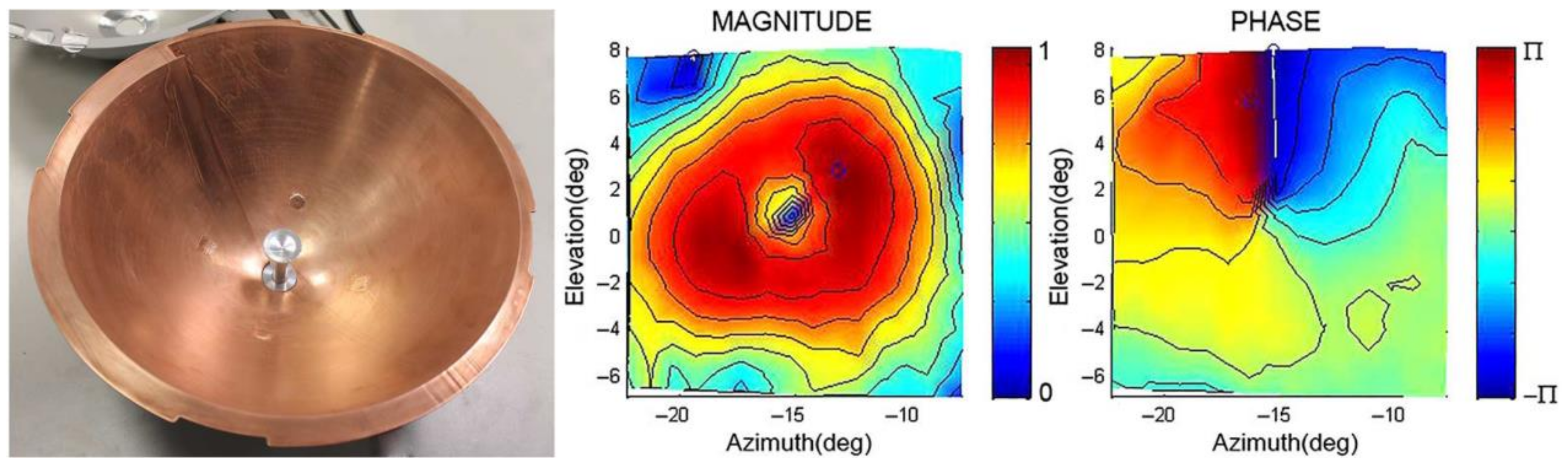
Figure 5.
Photography of the twisted reflector and the electric-field magnitude and phase patterns measured in the far-field at 17.2 GHz [33].
Figure 5.
Photography of the twisted reflector and the electric-field magnitude and phase patterns measured in the far-field at 17.2 GHz [33].

Figure 6.
Three dimensional (3D) printed dielectric structure mimicking placed on a flat perfect electrical conductor (PEC) surface mimicking a helicoidal parabolic reflector. The near-field and far-field results show a broadband frequency operation from 8 GHz to 16 GHz, thanks to the use of non-resonant dielectric structures [44].

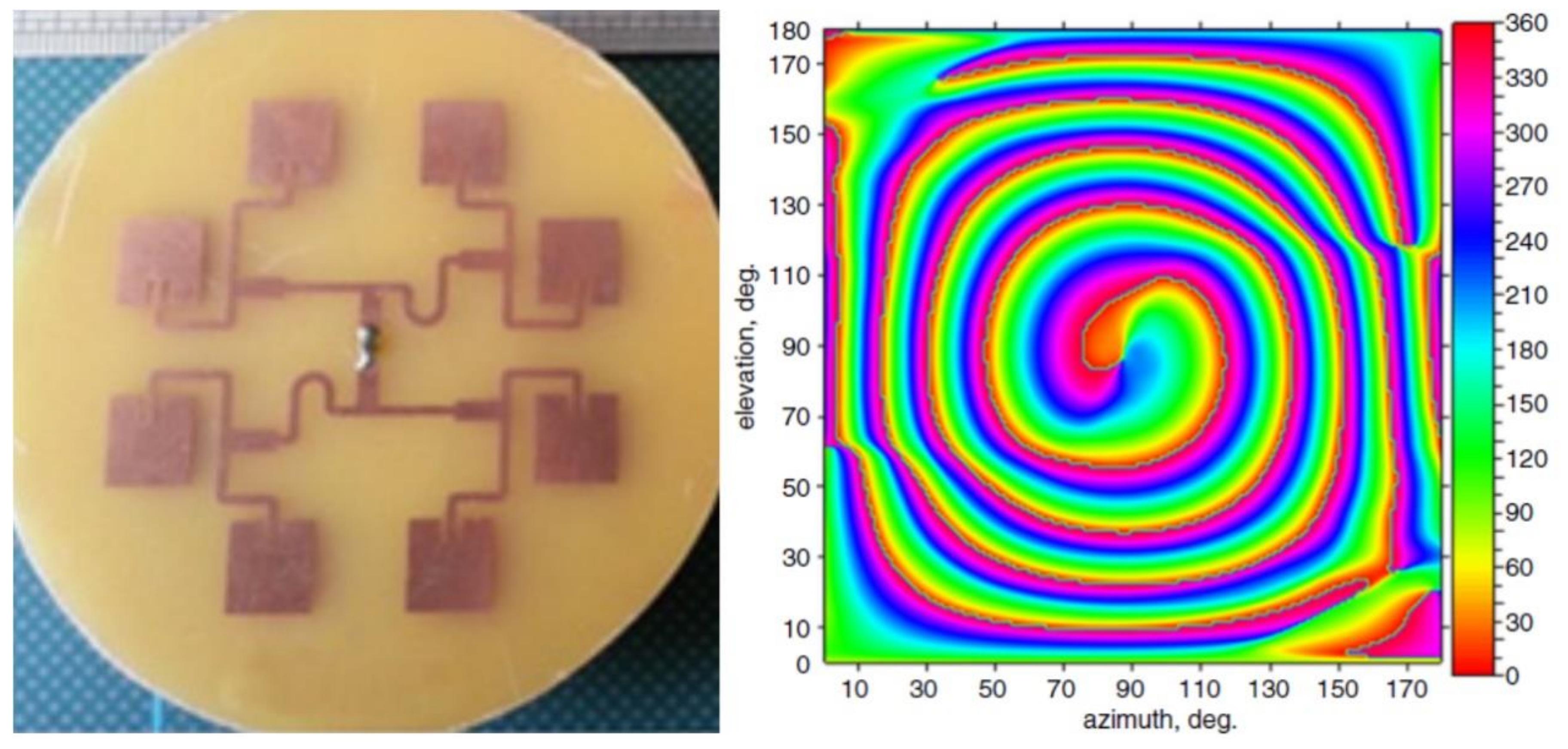
Figure 7.
Photography of the first experimental prototype of a phased antenna array for OAM vortex wave generation and its measured phase pattern [36].
Figure 7.
Photography of the first experimental prototype of a phased antenna array for OAM vortex wave generation and its measured phase pattern [36].

Figure 8.
Reflective OAM metasurfaces based on propagation phase. (a) Linear polarized (LP) vortex beams [51]. (b) Wideband linear polarized vortex beams [52]. (c) Double-layered unit for wideband vortex beams [53]. (d) Polarization insensitivity OAM metasurfaces [54].
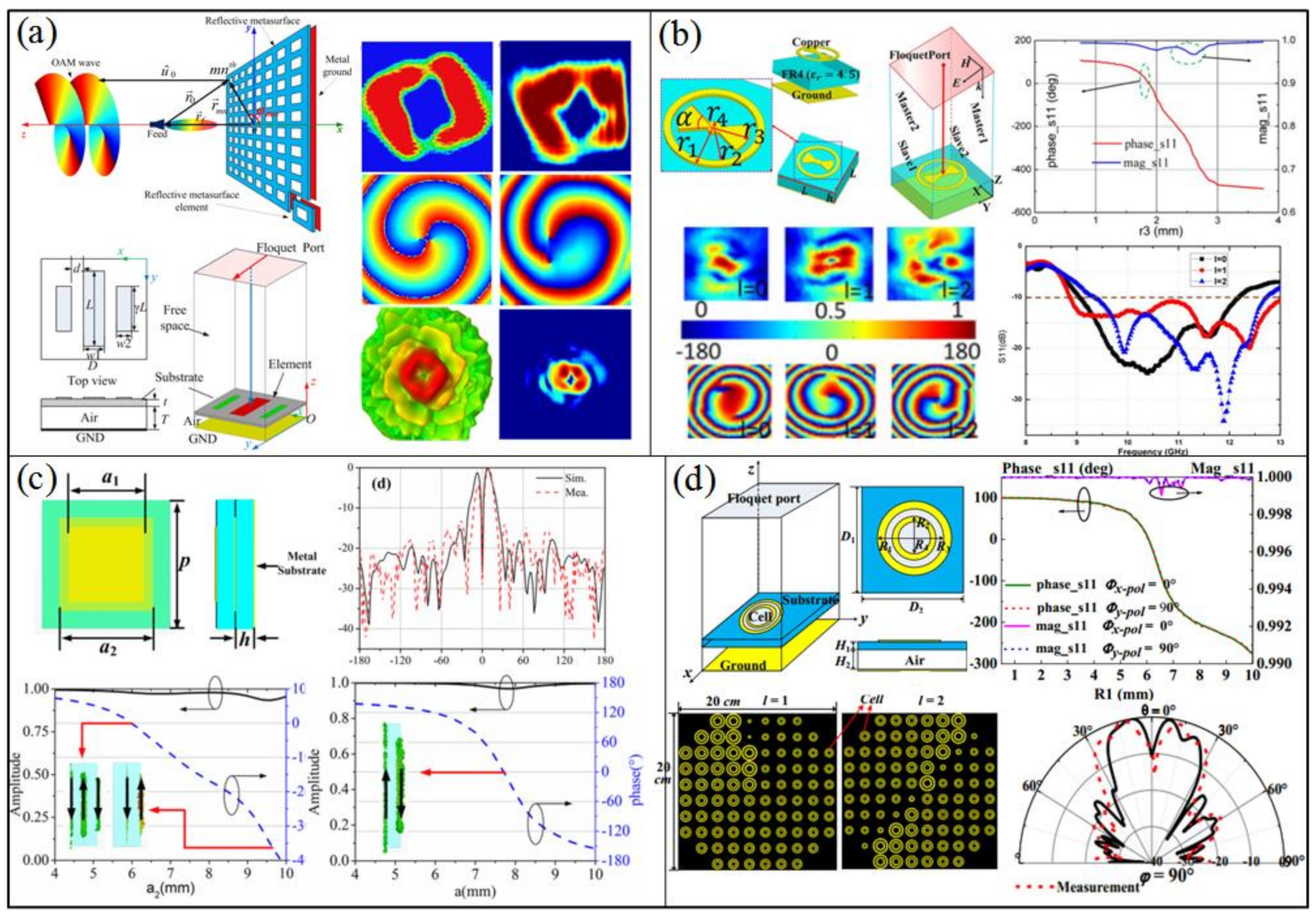
Figure 9.
Reflective OAM metasurfaces based on geometric (PB) phase. (a) Double arrow-shaped metasurface [55]. (b) N-shaped resonator metasurface [56]. (c) Double-layered cross dipoles metasurface for a wideband vortex beams [57]. (d) OAM metasurface based on perfect electric conductor-perfect magnetic conductor (PEC-PMC) elements [60].

Figure 10.
Digital coding OAM reflective metasurface. (a) One-bit passive OAM metasurface [61]. (b) One-bit active OAM metasurface [62]. (c) One-bit dual polarization OAM metasurface [63]. (d) Five-bit multi-polarization OAM metasurface [64].

Figure 11.
Multiplexed OAM reflective metasurfaces. (a) Single linear polarization reflective metasurface to generate multiple vortex beams [65]. (b) Circular polarized (CP) wave decoupling to achieve multiplexed vortex beams [66]. (c) Full polarization multi-beams [67]. (d) A decoupling method to generate dual CP vortex beams at different frequencies [68].

Figure 12.
Transmissive OAM metasurfaces. (a) OAM metasurfaces based on MEFSS [72]. (b) OAM metasurfaces based on photon spin Hall effect (PSHE) unit of two double-headed arrows [73]. (c) OAM metasurfaces based on complementary split ring resonators [74]. (d) OAM metasurfaces based on PSHE unit of Z-shaped cell [75]. (e) OAM metasurfaces based on cross bar and holey metallic ring resonator [76]. (f) OAM metasurfaces based on ABA structure [70].

Figure 13.
(a) OAM metasurfaces based on multi-layer CP conversion unit [77]. (b) Vortex beams multiplexing based on CP wave [79]. (c) Multiple OAM modes by active metasurface [78]. (d) CP wave decoupled OAM metasurface [80].

Figure 14.
Non-diffraction OAM metasurfaces and metamaterials. (a) A collimating metalens [47]. (b) A collimating all-dielectric metamaterial medium [50]. (c) A metasurface to generate non-diffraction vortex beams and convert the polarization of the LP wave [81]. (d) A converging OAM metasurface and a non-diffracting OAM metasurface [82].

© 2020 by the authors. Licensee MDPI, Basel, Switzerland. This article is an open access article distributed under the terms and conditions of the Creative Commons Attribution (CC BY) license (http://creativecommons.org/licenses/by/4.0/).
Share and Cite
MDPI and ACS Style
Zhang, K.; Wang, Y.; Yuan, Y.; Burokur, S.N. A Review of Orbital Angular Momentum Vortex Beams Generation: From Traditional Methods to Metasurfaces. Appl. Sci. 2020, 10, 1015. https://doi.org/10.3390/app10031015
AMA Style
Zhang K, Wang Y, Yuan Y, Burokur SN. A Review of Orbital Angular Momentum Vortex Beams Generation: From Traditional Methods to Metasurfaces. Applied Sciences. 2020; 10(3):1015. https://doi.org/10.3390/app10031015
Chicago/Turabian StyleZhang, Kuang, Yuxiang Wang, Yueyi Yuan, and Shah Nawaz Burokur. 2020. "A Review of Orbital Angular Momentum Vortex Beams Generation: From Traditional Methods to Metasurfaces" Applied Sciences 10, no. 3: 1015. https://doi.org/10.3390/app10031015
Note that from the first issue of 2016, this journal uses article numbers instead of page numbers. See further details here.