Multi-Level Buffering Services Based on Optical Packet Encoding of Composite Maximal-Length Sequences in a GMPLS Network


1
School of Electrical and Computer Engineering, Nanfang College of Sun Yat-Sen University, Guangzhou 510970, China
2
College of Intelligence, National Taichung University of Science and Technology, Taichung 40401, Taiwan
*
Author to whom correspondence should be addressed.
Appl. Sci. 2020, 10(3), 730; https://doi.org/10.3390/app10030730
Submission received: 5 December 2019
/
Revised: 13 January 2020
/
Accepted: 20 January 2020
/
Published: 21 January 2020
(This article belongs to the Special Issue Fiber Optic Communication)
Abstract
:Generalized multi-protocol label-switching (GMPLS) provides packet-switching with multiple speeds and quality-of-services (QoSs). Packet buffering in GMPLS reduces packet loss by resolving the conflicts between packets requesting for a common channel. Presently, due to the diversity of multimedia applications, enabling multiple services in networks has become necessary. In this paper, a family of codes known as composite maximal-length sequence (CMLS) codes is introduced into an optical buffering scheme based on code-switching. A given number of available CMLS codes is divided into several code subsets. The buffer selects an unused CMLS code from a code subset and assigns it to the incoming packet. When all codes in a specific subset have been distributed to the queued packets, a free CMLS code in another subset is chosen for the new arrival. To achieve multi-level buffering services, the partition scenario with a lower subset number but with a higher number of codes in an individual subset is used as a code-assigning method for buffering high-QoS users. A two-level buffering system is demonstrated by examining the QoS of each class in terms of packet-dropping probability (PDP). The results show that different levels of PDPs can be effectively supported by a common buffer architecture.
1. Introduction
Generalized multi-protocol label-switching (GMPLS) provides packet-switching with multiple speeds and quality-of-services (QoSs) over optical networks in the time, wavelength, and space domains [1,2,3]. The typical quality comes from adopting the packet process operated by an internet protocol. The superiority of GMPLS is due to a unified control plane that includes separate network layers, and transparent data transmissions can be supported in a continuously changing environment. If the edge nodes for a connection of a packet flow are in different networks, GMPLS can merge new and previous networks and automatically set up a link configuration. Such advantages have drawn attention to GMPLS and it has achieved a lot in optical packet-switching (OPS) networks [4,5,6].
However, a packet stops switching in GMPLS if conflicts about the resources of channels or paths happen. When conflicts come into existence, resolution algorithms based on optical buffering take action. Buffering management at the core codes deals with packets that simultaneously compete to obtain the same resource [7,8,9,10,11,12]. The goal of packet buffering is to reduce the packet loss to the lowest possible level. As the OPS network will experience less packet-dropping, GMPLS with conflict resolution can support the development of future OPS networks. Optical buffering schemes can be generally boiled down to three categories: fiber delay line [7,8], wavelength conversion [9,10], and code-switching [11,12].
As the components of optical codecs have reached a mature state, code-switching has been emphasized in all optical buffering designs. The multiplexing technique of optical coding provides users with a shared bandwidth to employ asynchronous packet transmission [13,14,15]. Presently, networks are known for their diverse multimedia applications, so enabling multi-service data transmissions has become necessary. Several optical coding schemes have been proposed to achieve differentiated services in access networks. In [16], the parameters of optical code-words, such as length and weight, were changed to offer new data rates. To change the QoS, frequency hopping was combined with multi-wavelength optical codes in a two-dimension coding system [17].
In this paper, a family of codes known as composite maximal-length sequence (CMLS) codes [18,19] is introduced into a buffering scheme where packets are queued in the optical domain. Although code-switching can be treated as a promising scheme in optical buffering, it only provides a single-level buffering service in most cases. The contribution of this paper is that we consider the multiple schemes of partitioning a CMLS code set, design the corresponding CMLS codec in the buffer architecture, and model the buffering processes to obtain the performance curves that show various levels of packet-dropping probabilities (PDPs).
In the proposed scheme, a fixed number of CMLS codes is equally divided into several subsets. The partition scenario with a lower subset number but with a higher number of codes in an individual subset is used as an encoding method to achieve packet buffering for high-QoS users. To examine the buffering performance in detail, the QoS index of the PDP of different classes of users is studied. The PDP is applied to describe a scenario in which a buffer is full, and no more packets are allowed to enter it. In the buffering model that we use to derive the PDP, the packet traffic at the system inputs and outputs behaves as described in Erlang’s model [20,21].
2. Procedures for Constructing a Composite Maximal-Length Sequence (CMLS) and the Codec Design
In this paper, packet buffering in GMPLS is achieved by encoding each queued packet with a CMLS code composed of two extended maximal-length sequences (MLSs). A family of MLS codes includes KM code-words, where KM is called code cardinality. Each code-word has NM binary elements of {0, 1}, where NM = 2m − 1 is known as the MLS length and m is a positive integer larger than 1. A general way to describe the characteristics of a family of codes is to employ the expression of (NM, ωM, θM), where ωM and θM denote the auto- and cross-correlation of MLS codes. ωM is also known as the code weight, or the number of chips “1” in a MLS code-word, while θM is defined as the number of the overlapping chips “1” between any two different code-words in a family of MLS codes. The correlation properties between two MLSs in a code set are ω = (NM + 1)/2 and θ = (NM + 1)/4. Moreover, MLSs have a periodical-shift property, where an MLS belongs to the original code set after cyclically shifting any number of chips. The construction of a CMLS can be performed in three steps. First, select two MLS codes, Mi () and Mj (), with the code length of and , respectively, where 1 ≦ i ≦ and 1 ≦ j ≦ ; second, extend both Mi () and Mj () to the vectors with the length of the lowest common multiple of
and
by repeating them multiple times; finally, add these two extended code-words via the module-2 summation. Based on the above steps, the structuring of the CMLS code set of length N = can be summarized as follows:
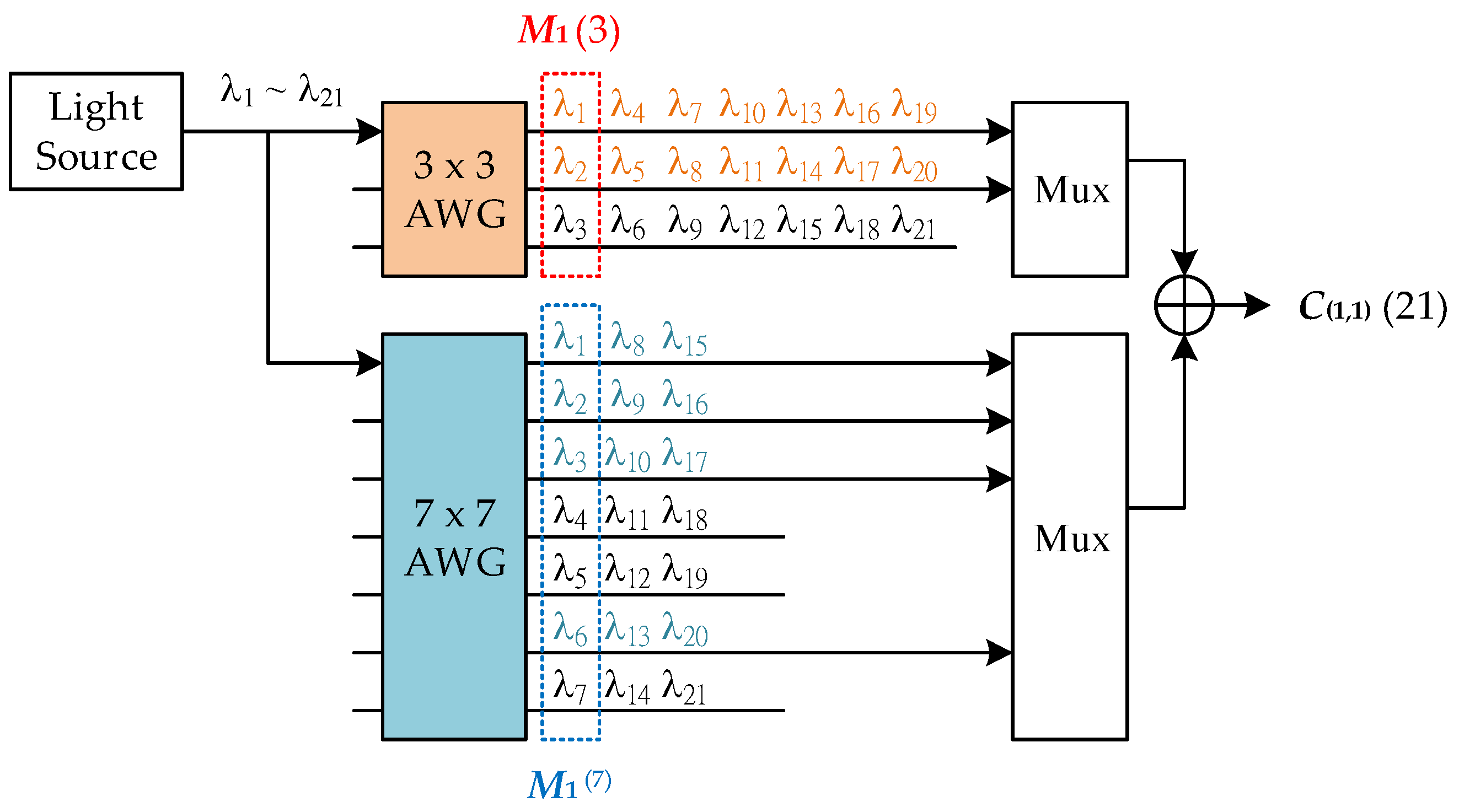
where denotes the operation of module-2 summation. Based on (1), one can find a CMLS set made of Mi () and Mj () that has N code-words in it. Figure 1 shows the construction of C(1,1)(21) with N = 21 based on M1 (3) = [110] and M1 (7) = [1110010].
The correlation property between any two code-words in a common family of CMLS codes is an important index for describing the code characteristics. The correlation values among CMLS codes with N are expressed as:
where denotes the dot-product operation. Based on (2), the autocorrelation for a CMLS code-word is fixed, while the cross-correlations between any two different CMLS code-words may vary, where the values are limited to three levels. As a CMLS is made from MLSs, both types of sequences have several similar characteristics, such as the mathematical expression of code weight or autocorrelation, and the cyclic-shift property. The latter indicates that when a CMLS C(i,j)(N) is known, all sequences in the code set can be found in Tm[C(i,j)(N)], where Tm[ ] denotes an operator that cyclically shifts a CMLS for m elements in right direction, where 0 ≦ m ≦ N − 1. Figure 2 shows two correlation functions, θ = C(1,1)(21)⊙Tm [C(1,1)(21)] and θ = C(1,1)(21)⊙Tm [C(1,1)(21)], where C(1,1)(21) is the complementary CMLS that describes that chips “1” and “0” are in the inverse positions of C(1,1)(21). In this figure, it can be observed that the CMLS has a good correlation property, as the autocorrelation value is large while the cross-correlation values remain relatively small.
To design the codecs of the CMLS codes, arrayed waveguide grating (AWG) was employed. AWG acts as a de-multiplexer that routes each of the input wavelengths to a specific output port. Figure 3 shows the encoder of C(1,1)(21), which consists of a 3 × 3 and a 7 × 7 AWG. The encoder input is a light source with a bandwidth that ranges from λ1 to λ21, including 21 wavelengths. One of the basic codes for constructing C(1,1)(21) is M1 (3) = (110), which is represented as the optical signal of (λ1λ20). These two wavelengths, λ1 and λ2, are obtained at the first and the second output of the 3 × 3 AWG. As shown in Figure 1, before generating C(1,1)(21), an extended vector that includes seven duplicates of M1 (3) is required. The signal of each duplicate in the extended vector is obtained by employing the wavelength routing property of AWG known as the free-spectral range (FSR). For an M × M AWG, if the signal of the light source enters the 1st input port, the wavelengths shown at the i-th output port are λi, λi+M, λi+2M …, where i + kM is less than or equal to the maximum wavelength number. Therefore, the second duplicate of M1 (3) is represented as the signal of (λ4λ50), while the third is (λ7λ80), and the remaining duplicates have similar wavelength distributions.
The other code basis, M1 (7) = (1110010), is composed of four wavelengths in its signal representation (λ1λ2λ300λ60). Similarly, the signal component of the extended vector of M1 (7) is obtained from the wavelengths appearing at 1st, 2nd, 3rd, and 5th outputs of the 7 × 7 AWG. The wavelength components at each AWG’s outputs are combined and sent to a module-2 adder for generating the final CMLS. Using optical wavelength signals to represent the chip distribution in a code sequence is known as spectral-amplitude-coding (SAC), which has been used a lot in optical access and switching networks due to its system simplicity. In addition to C(1,1)(21), other CMLS codes in the same code set can be generated from the shared encoder, as AWG has the cyclic-shift property for wavelength distributing. Such a property can also be found in the chip distributions of CMLSs and MLSs. An arbitrary CMLS C(i,j)(21) can be obtained by passing the light source signal to the i-th input of the 3 × 3 AWG and the j-th input of the 7 × 7 AWG without modifying any connections and components at the grating’s output ports.
Figure 4 depicts the decoder of C(1,1)(21) with a 21 × 21 AWG. The received signal is directed to the 1st input port. The wavelength signals sent to the upper multiplexer match the positions of chip “1” in C(1,1)(21), while the ones sent to the lower multiplexer match the positions of chip “0”. The optical signals at each multiplexer’s output are converted to an electrical current by a photodetector. After the lower current is subtracted from the upper, the subtraction result is passed to a threshed device. To identify CMLS code C(i,j)(21) = Tm [C(1,1)(21)], the received signal is sent to the m-th input of the AWG decoder. The decoding function can be expressed by the following equation of correlation subtraction:
According to (3), if a packet encoded with C(1,1)(21) enters the corresponding decoder, the output value is 10, which can be obtained from the upper case in (3) by substituting = 3 and = 7. If the decoder does not match the code carried by the packet, the output values would be −2, −4, and 0. We select the median between 10 and 0 as the threshold to determine whether the decoder matches the received coded signal. If the signal value at the decoder output is larger than 5, it indicates that C(1,1)(21) is presented.
3. Scenarios of Multi-Level Buffering Services and Performance Evaluations
The architecture of the proposed scheme capable of providing multi-service buffering is shown in Figure 5. In this scenario, two packets competing for a common output port are considered. At the buffer input ports, packets carrying CMLS signals are decoded by decoder arrays to generate photocurrents with amplitudes that are proportional to the power variations of the optical payloads. By considering the CMLSs that had been occupied by the existing optical packets in the buffer, the control unit decides which new sequences will be used to encode the incoming packets waiting to be queued. To perform optical encoding, an electrical switch forwards the baseband-decoded signals to optical modulators, and then the optical carriers are sent to the corresponding encoders. Please note that in this case, a packet carrying C(1,1)(21) has existed in the buffer, so the identical sequence carried by the input packet is switched into another available code C(3,1)(21). The other input packet retains its code C(2,1)(21) since it is not used by any queued packets. After renewing the attached codes, the encoded packets of different CMLSs are combined and passed to the output port.
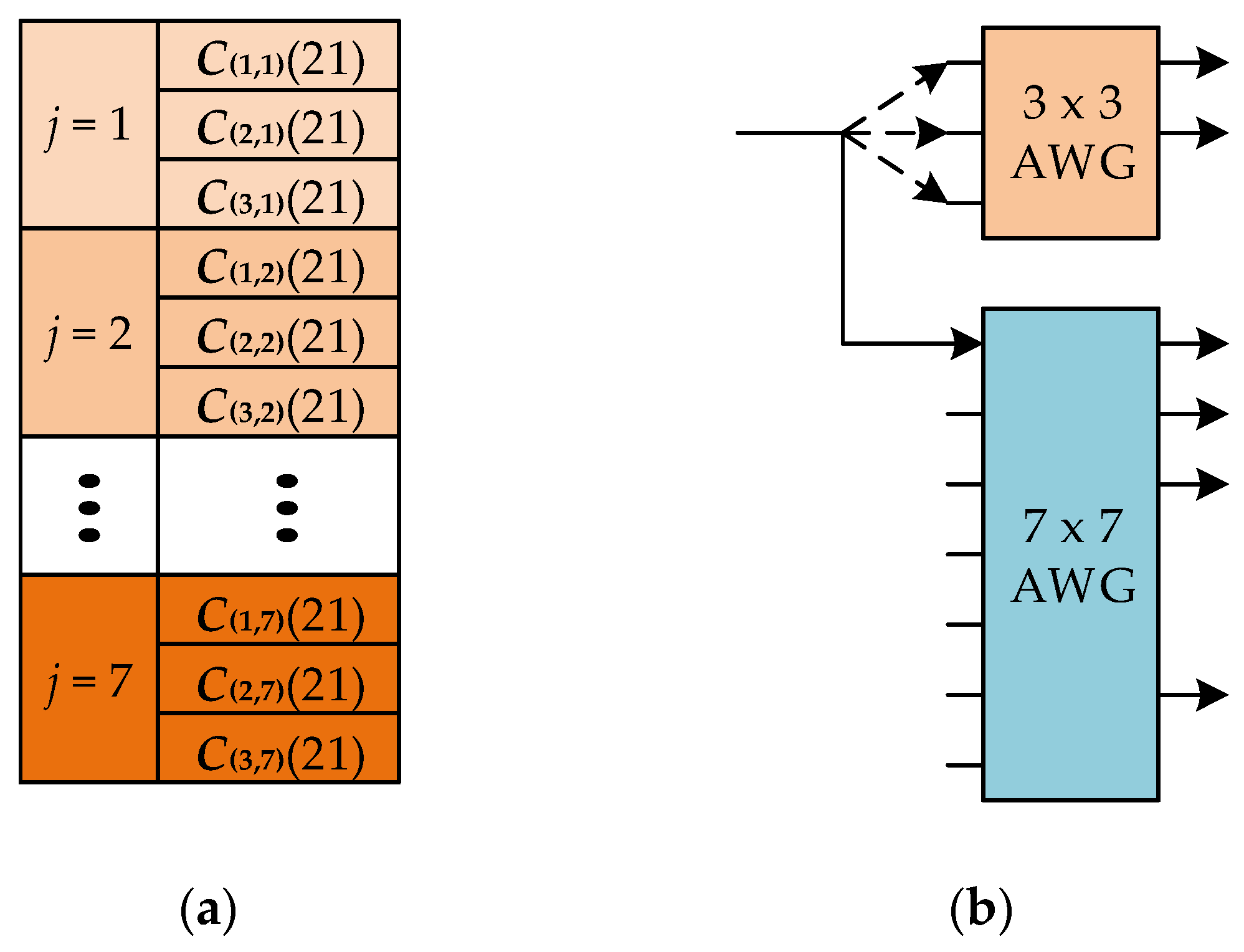
The use of CMLS codes in encoding packets provides the buffering service with variable performance. The partition of code set C(i,j)(21) for high-QoS users is shown in Figure 6a, where seven subsets C(i,1), C(i,2), …, C(i,7) are obtained, and each of them has three CMLS codes with a common index i. For high-QoS users, the preferred scenario is to partition the CMLS code set into max{, } subsets. In the example of = 3 and = 7, seven code subsets are obtained. If the codes in a certain subset are all occupied, the newly incoming packets with the codes in the same group will be sent to a free encoder generating a CMLS of different i. Figure 6b shows the encoder implementation corresponding to the code distribution in Figure 6a. The connection to the input ports of the upper 3 × 3 AWG is varied, and the one to the 1st input port of the lower 7 × 7 AWG is fixed to construct the code subset C(i,1), where 1 ≦ i ≦ 3. Another subset C(i,2) can be obtained by establishing the link to the 2nd input of the lower AWG.
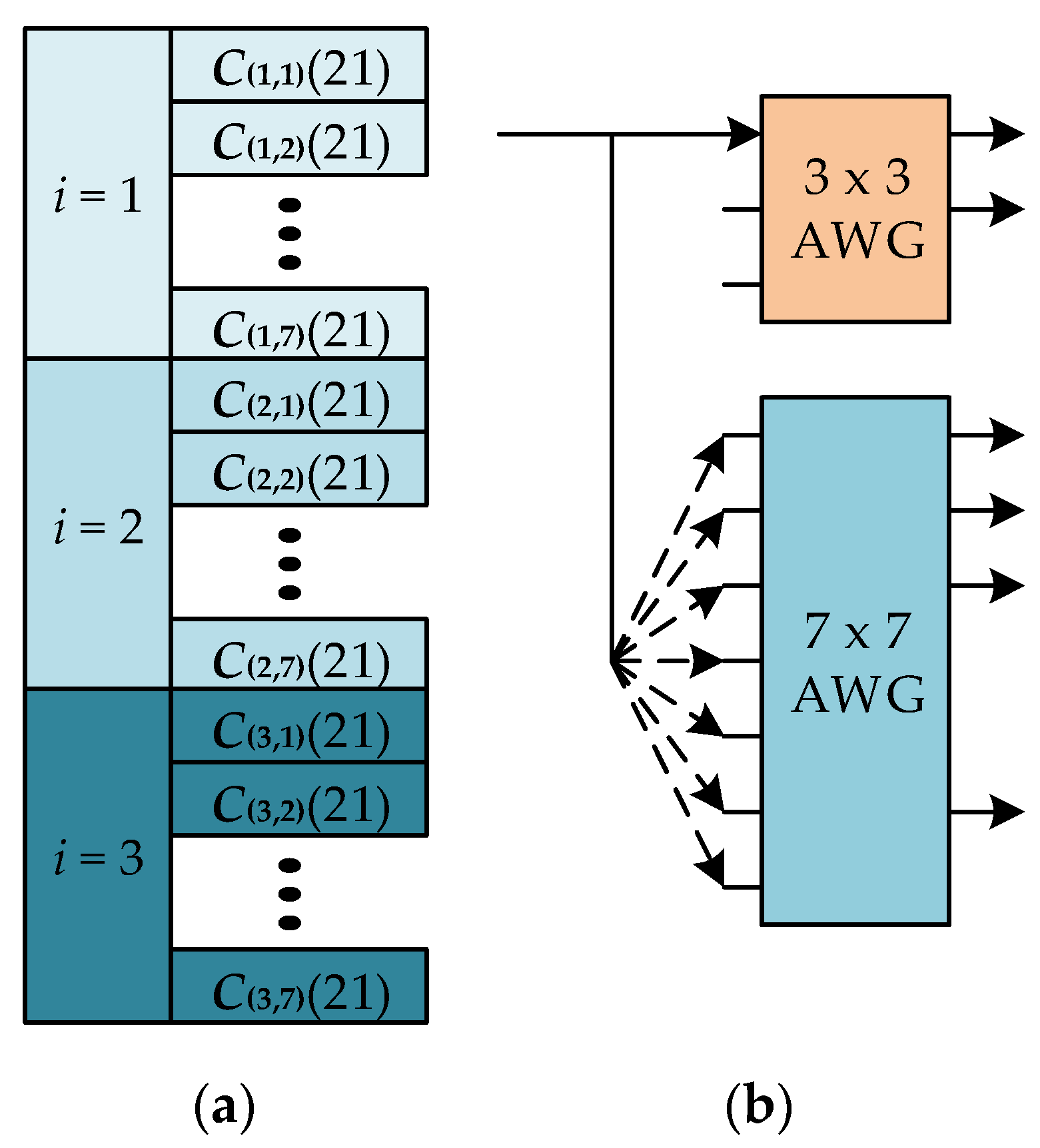
The other code distribution for low-QoS users is depicted in Figure 7a. The code set is divided into three subsets, C(1,j), C(2,j), and C(3,j). Each subset has seven CMLS codes. If the codes in a specific subset are assigned to the queued packets, the incoming packet is encoded with an available code signal with a different index j. Figure 7b shows the encoding process based on AWGs for low-QoS users. To distribute the codes in C(1,j), the link to the upper AWG is given while the one to the lower AWG is changing.
In a buffering system based on a CMLS, N is the maximum number of available codes. These codes are used for queuing packets when they arrive at the buffer. If the system is at capacity, an incoming signal is blocked and dropped. The buffering procedures can be described as a queue system where the AWG encoder is the single server, and the packet flow is the data source. The inter-arrival time μ between the two successive input packets is assumed to be the formula of the exponential process. The departure time of a packet leaving the buffer γ, which includes the latencies of finding a free code and optical decoding/encoding, is assumed to be the formula of the Poisson process. When a buffer of a unit CMLS subset is considered, it follows the characteristics of an M/M/1/NS system. Here, NS is defined as the number of CMLSs in a code subset. For the example of Figure 6 and Figure 7, the values of NS for high- and low-QoS users are respectively 7 and 3. The probability density function (PDF) of the number of coded packets in a buffer is treated as the steady-state probability of the used queuing system, which is given as [22]:
where 0 ≦ k ≦ NS. P0 denotes the probability of zero packets existing in the buffer, which can be obtained by using the normalized condition and expressed as
For a buffer that has been assigned CMLS codes of length N, it is at capacity when all N codes are distributed to the buffered packets. A newly incoming packet is dropped since the buffering space is not available. Therefore, the PDP is defined as the probability of N packets existing in the buffer, which is given as:
According to (6), the buffer model can be described as N/NS parallel M/M/1/NS systems.
In the proposed optical buffering process, the CMLS code used for encoding a queuing packet is determined by the following steps. First, the control unit in the buffer selects a code subset with at least one unoccupied code in it. Second, one of the unoccupied codes in the selected code subset is assigned to the packet. If the codes in a code subset are all occupied, this subset is neglected by the control unit during the code-searching process. Therefore, the probability of successfully finding an occupied code for packet encoding in the buffering process is related to N, NS, and N/NS. In (5) and (6), one could observe that PDP is determined by these three parameters. The relation between the parameters of N, NS, and N/NS is listed as follows:
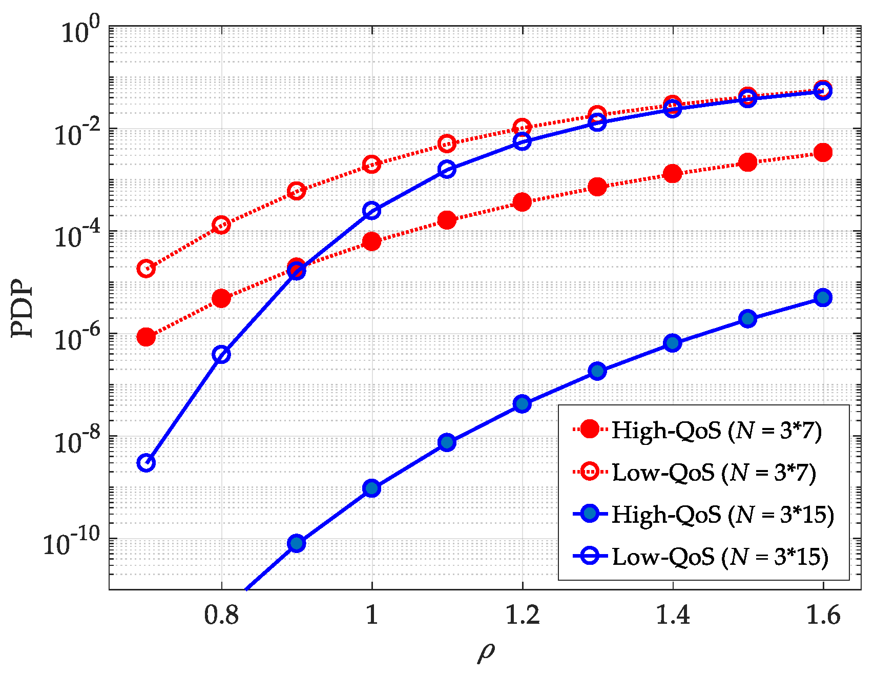
Figure 8 shows the PDPs of the two levels of buffering performance versus activity coefficient ρ, where ρ is defined as γ/μ. The figure compares the two scenarios of high- and low-QoS users for different CMLS lengths. The parameters for code lengths are listed as follows. For N = 21, = 3, and = 7, while for N = 45, = 3, and = 15. For a given code length (N = 21), the code assignment based on the partition of the code space with a larger subset number N/ = 7 improves the performance in terms of PDP, compared with the one with a smaller subset number N/ = 3. Please note that the difference between the twolevels of PDP becomes significant when the length difference between and increases. Furthermore, an increase in ρ leads to worse PDP performance. This is because the number of packets waiting in the input line grows, and the incoming packet number may exceed the buffer capacity.
The PDP of the buffering system for = 3 and = 7 is plotted versus the CMLS code length N in Figure 9. The activity coefficient ρ in the figure is 3.2. The buffer performance is improved by increasing the code length since more packets can be allocated in the system. When N becomes large, the difference between and is also increased, and therefore the gap between the two levels of PDPs becomes notable. For the high-QoS users, to reach the lowest PDP, the partition scheme with the maximum subset number should be chosen.
To design a buffering scheme that supports more than two classes of optical buffering services, we refer to the results of the numerical simulations in Figure 9, where various PDPs can be obtained by varying the code length N. For a given N, at most two levels of PDPs can be supported. Moreover, there are two sizes of AWGs in the encoder. To generate multiple CMLS code sets with different lengths, additional AWGs are required to be implemented in the codec. Such encoder design diversifies the levels of PDP performance, but the system complexity is also increased as more optical components are included in the buffer structure.
4. Conclusions
In this paper, we have proposed a new approach to support multi-level buffering services in GMPLS networks based on optical packet encoding. In this scheme, a code sequence known as CMLS and composed of two extended MLS codes is designed. We have presented a partition mechanism that divides the CMLS code space into multiple subsets, with each of them with an identical code number. To support the desired QoS, a code distribution for encoding the queued packets and an encoder setup based on an AWG corresponding to the code space partition are proposed. The partition scenario with a lower subset number but with a higher number of codes in an individual subset is used as an encoding method to achieve packet buffering for high-QoS users. To analyze the system performance, the traffic behavior at the buffer’s input and output and the PDF of the queued packet number in the buffer were obtained based on Erlang’s model. The results show that the buffering services for different QoS users can be supported by queuing the packets with multi-level PDPs. Furthermore, a larger difference between and results in a more significant performance gap between the high- and low-QoS users.
So far, we have considered the buffering performance in terms of PDP. Another general degradation in the system is bit-error rate (BER), which comes from the signals of the coded packets multiplexed in the same fiber. Based on the results in [23], the BER for a general SAC system is negligible (<10−9) when the user number is less than 50. However, when N increases, although one can expect a reduced PDP, the BER becomes notable since the number of overlapping coded packets grows. The combined effect of PDP and BER and their trade-off relation require further investigation.
Author Contributions
K.-S.C. contributed to the conceptualization, methodology, and writing of this paper. W.H. conceived the simulation setup and formal analysis and conducted the investigation. All authors have read and agreed to the published version of the manuscript.
Funding
This research was funded by the Department of Education of Guangdong Province, grant number 2018KTSCX322.
Conflicts of Interest
The authors declare no conflicts of interest.
References
- Kanj, M.; Rouzic, E.L.; Meuric, J.; Cousin, B.; Amar, D. Optical power control in GMPLS control plane. IEEE/OSA J. Opt. Commun. Netw. 2016, 8, 553–568. [Google Scholar] [CrossRef] [Green Version]
- Farghal, A.E.; Shalaby, H.M.H.; Kawasaki, Z. Multirate multiservice all-optical code switched GMPLS core network utilizing multicode variable-weight optical code-division multiplexing. IEEE/OSA J. Opt. Commun. Netw. 2014, 6, 670–683. [Google Scholar] [CrossRef]
- Huang, S.; Baba, K.; Murata, M.; Kitayama, K. Architecture design and performance evaluation of multi-granularity optical networks based on optical code division multiplexing. IEEE/OSA J. Opt. Commun. Netw. 2016, 5, 1028–1042. [Google Scholar] [CrossRef]
- Segawa, T.; Ibrahim, S.; Nakahara, T.; Muranaka, Y.; Takahashi, R. Low-power optical packet switching for 100-Gb/s burst optical packets with a label processor and 8 × 8 optical switch. IEEE/OSA J. Lightwave Technol. 2016, 34, 1844–1850. [Google Scholar] [CrossRef]
- Zhao, Z.; Wu, B.; Li, B.; Xiao, J.; Fu, S.; Liu, D. Multihop routing enabled packet switching with QoS guarantee in optical clos for data centers. IEEE/OSA J. Opt. Commun. Netw. 2018, 10, 624–632. [Google Scholar] [CrossRef]
- Lopez, V.; Hernandez, J.A.; De Dios, O.G.; Palacios, J.F.; Aracil, J. Multilayer traffic engineering for IP over WDM networks based on Bayesian decision theory. IEEE/OSA J. Opt. Commun. Netw. 2010, 2, 515–529. [Google Scholar] [CrossRef]
- Datta, A. Construction of polynomial-size optical priority queues using linear switches and fiber delay lines. IEEE/ACM Trans. Netw. 2017, 25, 974–987. [Google Scholar] [CrossRef]
- Lim, H. Number of tunable wavelength converters and internal wavelengths needed for cost-effective design of asynchronous optical packet switching system with shared or output fibre delay line buffer. IET Commun. 2013, 7, 1419–1429. [Google Scholar] [CrossRef]
- Hirayama, T.; Miyazawa, T.; Furukawa, H.; Harai, H. Optical and electronic combined buffer architecture for optical packet switches. J. Opt. Commun. Netw. 2015, 7, 776–784. [Google Scholar] [CrossRef]
- Liu, L.; Zhang, Z.; Yang, Y. In-order packet scheduling in optical switch with wavelength division multiplexing and electronic buffer. IEEE Trans. Commun. 2014, 62, 1983–1994. [Google Scholar] [CrossRef]
- Kazemi, R.; Rashidinejad, A.; Nashtaali, D.; Salehi, J.A. Virtual optical buffers: A novel interpretation of OCDMA in packet switch networks. J. Lightwave Technol. 2012, 30, 2964–2975. [Google Scholar] [CrossRef]
- Chen, K.S.; Chen, C.S.; Wu, S.L. Two-code keying and code conversion for optical buffer design in optical packet switching networks. Electronics 2019, 8, 1117. [Google Scholar] [CrossRef] [Green Version]
- Cherifi, A.; Jellali, N.; Najjar, M.; Aljunid, S.A.; Bouazza, B.S. Development of a novel two-dimensional SWZCC—Code for spectral/spatial optical CDMA system. Opt. Laser Technol. 2019, 109, 233–240. [Google Scholar] [CrossRef]
- Najjar, M.; Jellali, N.; Ferchichi, M.; Rezig, H. Spectral/spatial optical CDMA code based on diagonal eigenvalue unity. Opt. Fiber Technol. 2017, 38, 61–69. [Google Scholar] [CrossRef]
- Liu, M.; Wang, T.; Tseng, S. Throughput performance analysis of asynchronous optical CDMA networks with channel load sensing protocol. IEEE Photonics J. 2017, 9, 1–13. [Google Scholar] [CrossRef]
- Lin, J.Y.; Jhou, J.S.; Wen, J.H. Variable-length code construction for incoherent optical CDMA systems. Opt. Fiber Technol. 2007, 13, 180–190. [Google Scholar] [CrossRef]
- Baby, V.; Kwong, W.C.; Chang, C.Y.; Yang, G.C.; Prucnal, P.R. Performance analysis of variable-weight multilength optical codes for wavelength-time O-CDMA multimedia systems. IEEE Trans. Commun. 2007, 55, 1325–1333. [Google Scholar] [CrossRef]
- Huang, J.F.; Chen, K.S.; Lin, Y.S.; Li, C.Y. Reconfiguring waveguide-gratings-based M-signature codecs to enhance OCDMA network confidentiality. Opt. Commun. 2014, 313, 223–230. [Google Scholar] [CrossRef]
- Meng, S.H.; Chen, K.S.; Huang, J.F.; Yang, C.C. Orthogonal stacked composite M-sequence labels for quick packet routing over optical MPLS network. In Proceedings of the IEEE 28th Canadian Conference on Electrical and Computer Engineering (CCECE), Halifax, NS, Canada, 3–6 May 2015. [Google Scholar]
- Beyranvand, H.; Salehi, J.A. Multiservice provisioning and quality of service guarantee in WDM optical code switched GMPLS core networks. J. Lightwave Technol. 2009, 27, 1754–1762. [Google Scholar] [CrossRef]
- Beyranvand, H.; Salehi, J.A. All-optical multiservice path switching in optical code switched GMPLS core Networks. J. Lightwave Technol. 2009, 27, 2001–2012. [Google Scholar] [CrossRef]
- Cassandras, C.G.; Lafortune, S. Introduction to Discrete Event Systems; Springer: New York, NY, USA, 2006. [Google Scholar]
- Yang, C.C. The application of spectral-amplitude-coding optical CDMA in passive optical networks. Opt. Fiber Technol. 2008, 14, 134–142. [Google Scholar] [CrossRef]
Figure 1.
Construction of a composite maximal-length sequence (CMLS) with a length of 21 based on two maximal-length sequence (MLS) codes with a length of 3 and 7.
Figure 1.
Construction of a composite maximal-length sequence (CMLS) with a length of 21 based on two maximal-length sequence (MLS) codes with a length of 3 and 7.

Figure 2.
The correlation values and the complementary correlation values of CMLS C(1,1)(21).

Figure 3.
The encoder architecture of CMLS C(1,1)(21) based on arrayed waveguide grating (AWG). Mux: Multiplexer.
Figure 3.
The encoder architecture of CMLS C(1,1)(21) based on arrayed waveguide grating (AWG). Mux: Multiplexer.

Figure 4.
The decoder architecture of CMLS C(1,1)(21) based on AWG. Mux: Multiplexer. PD: Photodetector.
Figure 4.
The decoder architecture of CMLS C(1,1)(21) based on AWG. Mux: Multiplexer. PD: Photodetector.

Figure 5.
The optical buffering architecture with optical encoding/decoding of the CMLS. ODA: optical decoder array; OEA: optical encoder array; E/O: electrical-to-optical conversion.
Figure 5.
The optical buffering architecture with optical encoding/decoding of the CMLS. ODA: optical decoder array; OEA: optical encoder array; E/O: electrical-to-optical conversion.

Figure 6.
The optical buffering scenario for high quality-of-service (QoS) packets. (a) Code partition method; (b) encoder setup.
Figure 6.
The optical buffering scenario for high quality-of-service (QoS) packets. (a) Code partition method; (b) encoder setup.

Figure 7.
The optical buffering scenario for low-QoS packets. (a) Code partition method; (b) encoder setup.
Figure 7.
The optical buffering scenario for low-QoS packets. (a) Code partition method; (b) encoder setup.

Figure 8.
The packet-dropping probability (PDP) of two-level buffering performance versus activity coefficient.
Figure 8.
The packet-dropping probability (PDP) of two-level buffering performance versus activity coefficient.

Figure 9.
The PDP of two-level buffering performance versus CMLS code length.

© 2020 by the authors. Licensee MDPI, Basel, Switzerland. This article is an open access article distributed under the terms and conditions of the Creative Commons Attribution (CC BY) license (http://creativecommons.org/licenses/by/4.0/).
Share and Cite
MDPI and ACS Style
Chen, K.-S.; Hong, W. Multi-Level Buffering Services Based on Optical Packet Encoding of Composite Maximal-Length Sequences in a GMPLS Network. Appl. Sci. 2020, 10, 730. https://doi.org/10.3390/app10030730
AMA Style
Chen K-S, Hong W. Multi-Level Buffering Services Based on Optical Packet Encoding of Composite Maximal-Length Sequences in a GMPLS Network. Applied Sciences. 2020; 10(3):730. https://doi.org/10.3390/app10030730
Chicago/Turabian StyleChen, Kai-Sheng, and Wien Hong. 2020. "Multi-Level Buffering Services Based on Optical Packet Encoding of Composite Maximal-Length Sequences in a GMPLS Network" Applied Sciences 10, no. 3: 730. https://doi.org/10.3390/app10030730
Note that from the first issue of 2016, this journal uses article numbers instead of page numbers. See further details here.