Control Strategy Development of Driveline Vibration Reduction for Power-Split Hybrid Vehicles

1
Department of Vehicle Engineering, National Taipei University of Technology, Taipei 10608, Taiwan
2
College of Mechatronic Engineering, Guangdong University of Petrochemical Technology, Maoming 525000, Guangdong, China
*
Author to whom correspondence should be addressed.
Appl. Sci. 2020, 10(5), 1712; https://doi.org/10.3390/app10051712
Submission received: 16 January 2020
/
Revised: 1 February 2020
/
Accepted: 25 February 2020
/
Published: 2 March 2020
(This article belongs to the Special Issue Intelligent System Innovation)
Abstract
:In order to achieve better performance of fuel consumption in hybrid vehicles, the internal combustion engine is controlled to operate under a better efficient zone and often turned off and on during driving. However, while starting or shifting the driving mode, the instantaneous large torque from the engine or electric motor may occur, which can easily lead to a high vibration of the elastomer on the driveline. This results in decreased comfort. A two-mode power-split hybrid system model with elastomers was established with MATLAB/Simulink. Vibration reduction control strategies, Pause Cancelation strategy (PC), and PID control were developed in this research. When the system detected a large instantaneous torque output on the internal combustion engine or driveline, the electric motor provided corresponding torque to adjust the torque transmitted to the shaft mitigating the vibration. To the research results, in the two-mode power-split hybrid system, PC was able to mitigate the vibration of the engine damper by about 60%. However, the mitigation effect of PID and PC-PID was better than PC, and the vibration was able to converge faster when the instantaneous large torque input was made. In the frequency response, the effect of the PID blocking vibration source came from the elastomer was about 75%, while PC-PID additionally reduced 8% by combining the characteristics of the two control methods.
1. Introduction
With the advantages of low fuel consumption and low exhaust emissions, hybrid electric vehicles strike a balance between gasoline vehicles with high fuel consumption, exhaust emissions and electric vehicles with limited travel range. In the hybrid system, the internal combustion engine (ICE) is set to operate under the efficiency range, and the motor/generator (M/G) is operated at a low vehicle speed or when the power source and output need to be adjusted. The energy management of electric and ICE power systems, and the emission control have been studied and developed in different types of hybrid systems [1,2,3,4]. However, the power source setting causes the internal combustion engine to start and shut down frequently and unpredictably, and the mode shifting changes the torque of the power source greatly. Both situations may result in more obvious vibration of the driveline, which brings out the problem of comfort and decreases power transmission efficiency [5,6].
Numerous hybrid systems have been proposed recently, with commercially available vehicles mainly using the Toyota Hybrid System (THS) or Two-Mode power-split Hybrid (TMH) [7,8]. Hendrickson et al. [9] and Meisel [10] explained the mechanical structure and advantages of the transmission for the TMH system. For various driving needs, two Electric Variable Transmission (EVT) modes were provided to accommodate power requirements under low-speed/high-speed, and were paired with four sets of fixed gear ratios to overcome the operating limitations between power sources during mode conversion. These ensured that the internal combustion engine remains stable in the efficiency range at all speeds. This transmission consisted of two sets of planetary gears that connected power sources such as an internal combustion engine, two motors/generators, and amplified its output power to the wheels.
However, relying solely on the TMH system was not able to express the vibrate situation of the driveline. Ito et al. [11] explained that adding elastomers to the system could simulate the operation of the overall driveline accurately, and present the phenomenon caused by torque transfer. In addition to the half-shaft, this research added elastomer modules such as an internal combustion engine damper and tires to indicate the source of the low-frequency vibration on the driveline, and half shaft speed was fed back to control strategy for vibration reduction of the driveline system.
In addition, in terms of vibration reduction, the motor could be quickly fed back when vibration occurred due to the faster dynamic response and the speed-shifting function within the system, without changing the structure of the system. Canova et al. [5] introduced a belted starter/alternator (BSA) mild hybrid system with control of the electric motor to start and stop the engine smoothly. This paper focused on the control of the start and stop dynamics of a Hybrid Electric Vehicle (HEV) with a belted starter/alternator. Davis et al. [12] and Fesefeldt et al. [13] presented an integrated starter alternator model which generated a disturbance input decoupling torque command for the electric motor to cancel the engine torque ripples. Yang et al. [14] developed a control optimization strategy to lower the driveline fluctuation of an axially paralleled hybrid system. Wang et al. [15] studied the single-shaft parallel hybrid powertrain, and proposed a transition control method based on predictive control algorithm. He et al. [16] developed a three-stage control strategy to smooth the transition from electric mode to hybrid mode. Ito et al. [11] proposed a control strategy that within the signal planetary gear hybrid system, while the internal combustion engine was having a large torque output to cause vibration, the signal was sent to control logic to calculate torque feedback by the gear ratio relationship. The torque feedback would be sent back to the controller changing the motor torque output signal to an equal but reverse torque to cause vibration neutralization. Guo et al. [17] focused on the driveline vibration caused by the traction motor in the launch situation, and proposed a superposition control strategy to suppress the driveline vibration. Wang et al. [18] provided an improved genetic algorithm method to reduce the speed-up transient vibration of planetary power-split driveline system. For PID control, Herbst [19] introduced the active disturbance rejection control (ADRC) as an alternative for PID control. This research used a discrete-time case to speed up real time implementation in dynamic system. Liao [20] compared the current rotation speed with the expected rotation speed of the counter shaft when the internal combustion engine ran, and sent the difference to the PID controller. The torque feedback could neutralize the remaining vibration. However, the above two control methods were only for the internal combustion engine when starting. Thus, this research further explored the vibration reduction effect such as adding feedback control when a greater change in power source torque existed.
This research focused on improving the elastomer vibration in the TMH driveline caused by the instantaneous large torque from each power source. Two control methods were implemented to neutralize the vibration. One was using the motor output torque feedback generated by predicting the torque when the internal combustion engine started and shut down. The other one was adjusting the motor speed by comparing the monitored rotation speed of the output axis and the estimated rotation speed based on the stable vehicle speed. Finally, the characteristics of two control methods were combined to reduce vibration.
The remaining sections are as follows: the theoretical background and modeling of two-mode power-split hybrid system, the control strategies of vibration reduction, the results and comparison of vibration reduction, and the conclusions.
2. Two-Mode Power-Split Hybrid System Model
2.1. Two-Mode Power-split Hybrid System Transmission
The General Motors (GM) Two-Mode hybrid transmission system was applied in the research, as shown in Figure 1. This transmission system includes two sets of planetary gear mechanisms (P1, P2), two sets of brake clutch (CB4, CB12R), and two sets of power transfer clutch (C13, C234), as well as an internal combustion engine and two motors/generators (MG1, MG2) connected to the ring gear, the sun gear, and the planet carrier on P1, respectively. This system transferred the power from the power source to the output driving shafts.
This transmission system consisted of two continuous variable speed modes (EVT) to cover the needs for low speed, high-speed cruise, and rapid acceleration which also cooperated with four sets of fixed gear ratio to smoothen the mode shift. When the CB12R clutch was engaged, the torque was output by MG2 with the driving force need. When a certain speed was reached or the state of charge (SOC) was low, the engine would turn on to provide power, which was called EVT-1 mode, mainly used at low speed. When entering the high-speed segment, the CB12R would be loosened and the C234 clutch was engaged, so that the sun gear (S1) of P1 was connected to the ring gear (R2) of P2. This allowed the internal combustion engine to provide more power to the output, which was called EVT-2 mode. This research was aimed at the vibration of the driveline, and the situation of the remaining clutch would not be included.
In addition, in order to accurately grasp the situation of overall torque transmission, and present the speed adjusting function of M/G in the power system and the accelerating function of the internal combustion engine, the considerations of the moment of inertia of each component in the transmission system and the internal force between gears were added to further estimate the speed of each power source and output axis [21].
The torque angular acceleration relationship of the EVT-1 mode was exemplified in the following. In mode one, the clutch CB12R was locked, the internal combustion engine power was input to P1 and split, and P2 was operated with the reduction gear. At this time, the rotation speed relationship of each gear on P1 and P2 were as shown in Equations (1) and (2).
After the internal combustion engine was connected to the damper, it was connected with the ring gear (R1) of P1. MG1 was connected with the sun gear (S1), and MG2 was connected with the planet carrier (C1) to transmit the torque into the transmission system. According to the connection relationship between each power source and the transmission in Figure 1, the torque calculation formula Equations (3)–(5) were listed. Among them, , , and were the torque, moment of inertia, and rotation speed, respectively. The rest, ICE Damper end (coded as ED in below) and MG2 end, are presented in the following.
Sun gear end—MG1:
Ring gear end—ICE Damper:
Planet carrier end—MG2:
At the output of the transmission, due to the connection with the flexible shaft, a reaction force () was fed back to here when the power output to the shaft. Therefore, the transmission output axis angular acceleration calculation is shown in Equation (6). Wherein, the is the sum of the moment of inertia from the transmission output to the half-shaft.
Next, the above-mentioned formula was organized into a matrix form as the transmission torque calculation, as shown in Equation (7). Among them, , , , were the rotational speed of the internal combustion engine, the MG1, MG2, and the output axis of the transmission, respectively. The J6 × 6 matrix was shown in Equation (8).
Finally, the formulas were rearranged, and the rotation speed was set as demand. Through the information of the three power sources and reaction force from the shaft, the changes of the rotation speed of each power source were obtained.
2.2. Internal Combustion Engine Model
The internal combustion engine is the main power output source of the hybrid system, providing power under high torque demand and providing sufficient power for a vehicle to meet the driver’s driving requirement. The engine power changes with the cylinder pressure, which is not only the reason a great amount of vibration occurs, but also the main source of the low-frequency vibration of the driveline. In order to present the vibration situation of torque while outputting power, the torque caused by engine cylinder pressure was used as the engine output. The single-cylinder mechanism is shown in Figure 2.
The calculation formula of single-cylinder engine torque is as shown in Equation (9) [22]. Among them, , , P, , r, L, and are respectively the engine torque provided by the cylinder pressure (N-m), piston top area (), the cylinder pressure (psi), the atmospheric pressure (psi), the crankshaft radius (m), the connecting rod length (m), and the crank angle (deg).
A six-cylinder 3.6 L internal combustion engine was applied in this research. The torque values at the respective crank angles of each cylinder were listed and used to calculate the overall torque output of the engine. A torque curve with relative proportion was drawn according to the different throttle angles, as shown in Figure 3.
However, in an actual hybrid system, the internal combustion engine acts on the efficient zone, that is, it does not start the ignition in the general idle speed range, but only when the motor drives the internal combustion engine to a certain speed or above. This driving process also makes the piston move in the cylinder, but the power stroke is excluded due to no ignition. Since the compressibility of the air, when the piston nears the top dead center (TDC), the air pushes the piston down. This process can create torque vibration, which is relative small compared with engine torque pause with ignition. The mechanism of no ignition of the internal combustion engine before 1200 rpm was included in the research model, and the torque corresponding to different crank angles was established according to the throttle angle, as shown in Figure 4.
2.3. Flexible Shaft Module
Ideally, the components of a driveline connect to each other with rigid connection, which means the drive shaft is stiff, does not absorb energy, and is able to fully transmit the torque to the wheel after receiving external torque, and the vehicle produces the corresponding speed for driving requirement. However, the real-life drive shafts and even tires are elastomers, each with rotational stiffness and damping. After the force taken, a certain amount of energy will be absorbed. In addition, elastomers generate corresponding, oscillating torque feedback to the front and rear components when they are subjected to a large external torque in an instant.
Flexible shaft modules such as half shafts, tires and engine damper were established in this research. In order to perform the elastomers torsional vibration caused by an external torque, the elastic coefficient and damping were added. Taking the drive shaft as an example, after the drive shaft rotational speed received from the output of the transmission system () and shaft speed according to the vehicle speed (), the torque fed back to the transmission system was calculated according to Equations (10) and (11), which was also the output torque that the shaft transmitted to the differential. Finally, this torque information was transmitted to the final drive mechanism to calculate the driving force. The flexible shaft module was shown in Figure 5.
3. Vibration Reduction Control Methods
3.1. Pulse Cancellation (PC)
During engine start, the internal combustion engine was set to operate within the efficient range in the hybrid system, and the rotational speed can be increased sharply to reach the desired speed. This process is coupled with the vibrating torque from the internal combustion engine. A large amount of vibration happens and is transmitted to the output axis while starting-up the engine, resulted in a loss of comfort.
The system was able to prejudge the information about the operation of the internal combustion engine. Torque feedback of the faster transient response M/Gs was designed to reduce the output vibration caused by the start-up of the internal combustion engine. The vibration torque of the internal combustion engine to the transmission system was neutralized by M/Gs, and M/Gs, which also provided sufficient power to drive the vehicle, and the output axis torque could drive the wheel at a smoother curve (mean value). The torque design for both M/Gs was required to maintain the torque balance of the planetary gears.
The corresponding torque required for the output when the internal combustion engine was started was calculated, as shown in Equations (12) and (13). Among them, and are the torque feedback MG1 and MG2, which should neutralize the vibration while maintaining the balance of the system force. and are respectively the radius of sun gear and the ring gear of the compound planetary gear set.
3.2. Proportional-Integral-Derivative Control (PID)
PID control was applied in this research as another control method in addition to PC. When the vibration was sensed, the vibration was neutralized by corresponding torque feedback provided by the motors, which was also able to meet the power demand. The vehicle speed of the previous time step was recorded, and the corresponding transmission rotation speed was calculated as the reference. The calculation is shown in Equation (14). Among them, is the base speed of the transmission, is the vehicle speed, and r is the effective radius of the tire.
The previous time step actual rotation speed of the transmission was compared with reference speed, and the difference was sent into the PID controller to obtain the required vibration reduction torque feedback. The feedback started when a large change in speed occurred. The calculation is shown in Equations (15) and (16). Among them, is the actual rotational speed of the transmission, is the difference value of the rotational speed, Kp, KI, and KD are the gain values of the PID control, and u is the control effort needed for vibration reduction.
Finally, the control effort needed for vibration reduction was sent to the M/G instruction controller to adjust the torque for vibration reduction.
4. Simulation Results
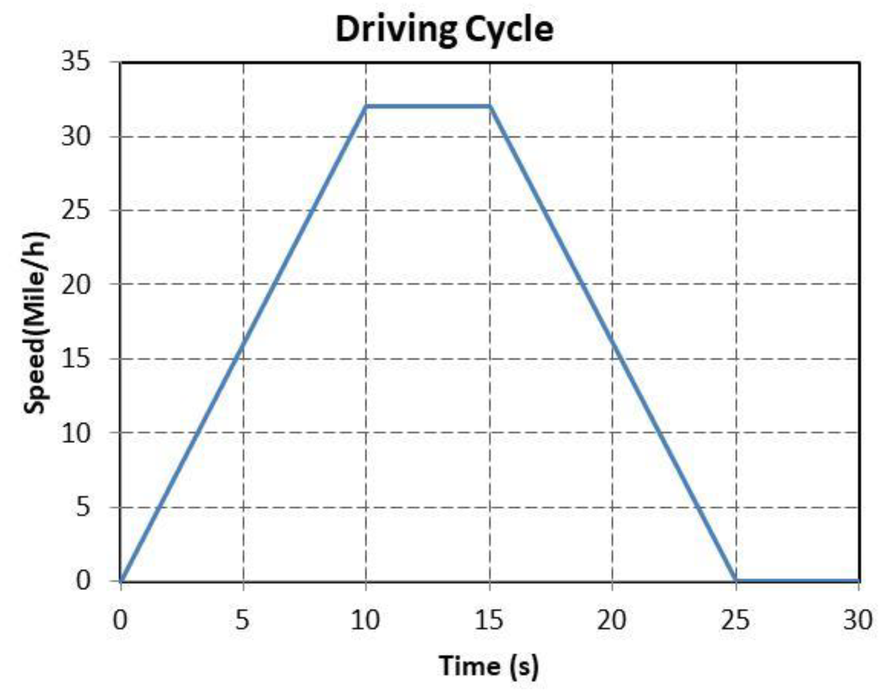
Driving Cycle
For a clearer representation of showing the elastomer vibration derived from the great change of M/G torque while the internal combustion engine was running and shifting modes during driving, the driving cycle applied in this research is shown in Figure 6. The vehicle initially accelerated to 32 miles per hour in 10 s, held in the fix-speed for 5 s and then dropped at rest in 10 s. In addition, this research set the mode shift at the time when the speed reached 30 miles per hour. It has shown a greater torque in the power source while the mode shifted.
After we added the control methods, the curve difference between the half-shaft vibration and the foundational model was observed, as shown in Figure 7. In addition, due to the torque of the power source changing greatly during acceleration and deceleration, as shown in the brown and blue frames, it resulted in significant vibration.
The comparison during vehicle acceleration and deceleration are shown in Figure 8 and Figure 9. The PC was able to reduce 593 N-m, about 22.5% of the peak-to-peak torque vibration during acceleration, but the PC mainly worked while the internal combustion engine was running. Thus, there was no vibration reduction during deceleration. PID and PC-PID were able to reduce 1055 N-m, about 40% of the peak-to-peak torque value during acceleration; and were able to reduce 419 N-m, about 14% during declaration. The overall effect of vibration reduction performed better than PC. However, the analysis of peak-to-peak vibration reduction during deceleration in the time domain was almost identical to PC. Therefore, the frequency domain response was needed to compare the difference between them. The effect of the Peak-to-Peak vibration reduction in half-shaft torque under each control method was compared, as shown in Table 1.
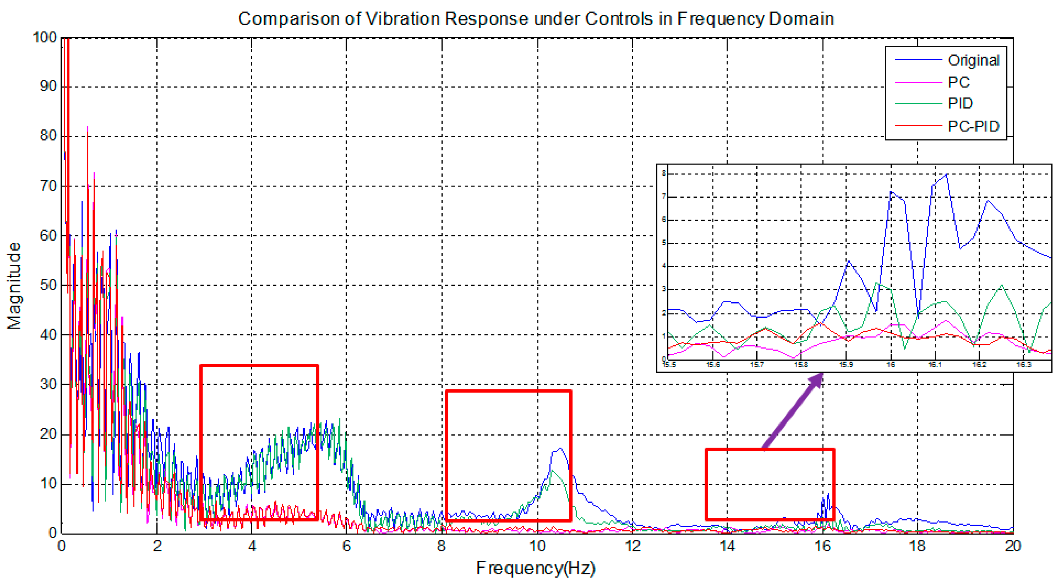
The half-shaft torque that was added to the control methods was then applied to the Fast Fourier Transform (FFT) to further confirm the effect of vibration reduction. The observation of the half-shaft torque and curve was shown in Figure 10. With PC, the amplitude at 16 Hz, the engine damper natural frequency, was reduced by 60%, and the amplitude at 11 Hz, the half-shaft natural frequency, was also reduced by about 25%. This result was mainly caused by the PC addressing only the vibration derived from the internal combustion engine. When the speed difference between the two ends of the damper decreased, the elastomer vibration would be reduced. Therefore, the vibration in the internal combustion engine damper reduced, and the vibration reduction was also able to be observed in the half-shaft natural frequency. However, the result of PC at 5 Hz was limited. By adding PID, the overall vibration was able to be reduced by more than 75%. In PID control, there was no similarity to the PC control method, which addressed only specific vibration source, but instead to reduce vibration according to the condition of the output axis, so the overall vibration reduction effect was ideal.
It was observed that low-frequency vibration was basically neutralized while adding the PC-PID curve. The overall vibration was able to reach over 75%, while the vibration reduction range at 16 Hz was about 8% higher than the effect of PID control. The range of vibration reduction of each control method at each frequency is shown in Table 2.
The two-mode power-split hybrid system was developed by vehicle manufactures, and the simulation model was accurately represented by the driveline system. The control strategies could be implemented in the vehicle without difficulty, and the benefits of vibration reduction could be expected.
5. Conclusions
This research established a forward Two-Mode Hybrid System module with MATLAB/Simulink, and incorporated elastomers such as engine damper, half-shaft, and tires to present the vibration situation of the driveline while driving. Previous research majorly focused on the driveline vibration caused by the traction motor during start and speed-up of vehicle. This research included the torque disturbance from cylinder pressure of the internal combustion engine, and control strategies were applied on electric motors that had quick responses to eliminate the vibration caused by the torque disturbance from the engine and driveline system. Vibration reduction control to the driveline was applied while the internal combustion engine was started or transmission was shifting modes. At the same time, without changing the power demand, three control methods were implemented. Such as Pulse Cancellation, which could reduce vibration by expecting vibration derived from the operation of the internal combustion engine and the angular acceleration of the transmission output, and PID control, which was able to adjust the speed of the faster-responsive motor/generator to reduce the vibration that was created by the angular velocity of the transmission output. The two control methods above were combined at the end. According to the data analysis in the previous sections, the following conclusions can be drawn:
- The vibration of the half-shaft torque feedback under each control method was observed in the time domain, the effect of PC was obvious when the vehicle accelerated and the internal combustion engine started up, the vibration reduction range of peak-to-peak value of torque was able to reach up to 22.5%. On the whole, however, the PID vibration reduction effect was more significant. The vibration reduction range of peak-to-peak value was able to reach up to 40% when the vehicle accelerated, the convergence speed was also faster, and the torque output was smoother. In addition, the effect in the time domain was not much different from the PID; therefore, the difference will be need to be determined by the frequency response.
- Apart from the observation of torque in the time domain, Fast Fourier Transform analysis of half-shaft torque of the vehicle was performed. In the frequency response of half-shaft torque, it was found that although the vibration was deduced with PC, and the vibration reduction at engine damper natural frequency, 16 Hz, was able to reach up to 60%. The vibration deduction at tire natural frequency, 5 Hz, was not obvious. The vibration reduction was relatively better in the PID frequency domain response. In the original vibration, sources of 5 Hz, 11 Hz, and 16 Hz were also effectively isolated, each reduced by 78.2%, 94.7%, and 78.7%, respectively, while the effect of vibration reduction of the PC-PID at 16 Hz increased another 8%, strengthening the effect of vibration reduction for the internal combustion engine.
- The vibration reduction analysis of this research focused on the low-frequency vibration, which was directly related to the comfort of the human body. This research simulated the vibration situation when the power source was operated by estimating of the torque of the internal combustion engine derived from the cylinder pressure and adding elastomers such as a internal combustion engine damper, Half-Shaft, and tires to the driveline. There are a few more ideas for the modeling process as follows, which could be applied to improve accuracy in the future.
The internal combustion engine module is derived from cylinder pressure and a connecting rod mechanism. It can be improved by a more comprehensive engine model that includes the transient response. It will be able to present the impact of vibration more accurately. This model could be derived from the cranking ICE and the actual ignition.
In the overall driveline, apart from the low-frequency vibration provided by the engine, there is a motor/generator that brings high-frequency vibration, and results in disturbance to the controller and sensor, which causes error in signal transduction. Therefore, adding an actual motor/generator model for processing high-frequency vibration analysis could be considered in the future.
Author Contributions
Conceptualization, H.-Y.H.; investigation, H.-Y.H.; methodology, T.-S.L.; project administration, J.-S.C.; software, J.-S.C.; validation, T.-S.L. and J.-S.C. All authors have read and agreed to the published version of the manuscript.
Funding
This research received no external funding.
Conflicts of Interest
The authors declare no conflict of interest.
References
- Doucette, R.T.; McCulloch, M.D. Modeling the Prospects of Plug-in Hybrid Electric Vehicles to Reduce CO2 Emissions. Applied Energy 2011, 88, 2315–2323. [Google Scholar] [CrossRef]
- Chau, K.T.; Wong, Y.S. Overview of Power Management in Hybrid Electric Vehicles. Energy Convers. Manag. 2002, 43, 1953–1968. [Google Scholar] [CrossRef]
- Wua, B.C.C.; Lina, Z.; Filipi, H.P.; Assanisa, D. Optimal Power Management for a Hydraulic Hybrid Delivery Truck. Veh. Syst. Dyn. 2004, 42, 23–40. [Google Scholar] [CrossRef]
- Wang, L.; Collins, E.G., Jr.; Li, H. Optimal Design and Real-Time Control for Energy Management in Electric Vehicles. IEEE Trans. Veh. Technol. 2011, 60, 1419–1429. [Google Scholar] [CrossRef]
- Canova, M.; Guezennec, Y.; Yurkovich, S. On the Control of Engine Start/Stop Dynamics in a Hybrid Electric Vehicle. J. Dyn. Sys. Meas., Control. 2009, 131, 061005. [Google Scholar] [CrossRef]
- Matijević, D.V.; Popović, V.M. Overview of Modern Contributions in Vehicle Noise and Vibration Refinement with Special Emphasis on Diagnostics. FME Trans. 2017, 45, 448–458. [Google Scholar] [CrossRef] [Green Version]
- Bayindir, K.; Ali, M.; Teke, A. A Comprehensive Overview of Hybrid Electric Vehicle: Powertrain Configurations, Powertrain Control Techniques and Electronic Control Units. Energy Convers. Manag. 2011, 52, 1305–1313. [Google Scholar] [CrossRef]
- Chang, C.C. The State of the Art of Electric, Hybrid, and Fuel Cell Vehicles. Proc. IEEE 2007, 95, 704–718. [Google Scholar] [CrossRef]
- Hendrickson, J.; Holmes, A.; Freiman, D. General Motors Front Wheel Drive Two-Mode Hybrid Transmission; 2009 SAE World Congress: Detroit, MI, USA, 2009; SAE paper number 2009-01-0508. [Google Scholar]
- Meisel, J. An Analytic Foundation for the Two-Mode Hybrid-Electric Powertrain with a Comparison to the Single-Mode Toyota Prius THS-II Powertrain; SAE World Congress: Detroit, MI, USA, 2009; SAE paper number 2009-01-1321. [Google Scholar]
- Ito, Y.; Tomura, S.; Sasaki, S. Development of Vibration Reduction Motor Control for Hybrid Vehicles. In Proceedings of the 33rd Annual Conference of the IEEE Industrial Electronics Society, Taipei, Taiwan, 5–8 November 2007; pp. 516–521. [Google Scholar]
- Davis, R.I.; Lorenz, R.D. Engine Torque Ripple Cancellation with an Integrated Starter Alternator in a Hybrid Electric Vehicle: Implementation and Control. IEEE Trans. Ind. Appl. 2003, 30, 1765–1774. [Google Scholar] [CrossRef]
- Fesefeldt, T.; Müller, S. Optimization and Comparison of Quick and Hybrid Start; SAE World Congress: Detroit, MI, USA, 2009; SAE paper 2009-01-1340. [Google Scholar]
- Yang, Y.; Zhang, Y.; Zhang, S.; Tian, J.; Hu, S. Control Strategy of Mode Transition with Engine Start in a Plug-in Hybrid Electric Bus. Energies 2019, 14, 1–20. [Google Scholar] [CrossRef] [Green Version]
- Wang, S.; Xia, B.; He, C.; Zhang, S.; Shi, D. Mode Transition Control for Single-Shaft Parallel Hybrid Electric Vehicle Using Model Predictive Control Approach. Adv. Mech. Eng. 2018, 10, 1–10. [Google Scholar] [CrossRef] [Green Version]
- He, R.; Tian, X.; Ni, Y.; Xu, Y. Mode Transition Coordination Control for Parallel Hybrid Electric Vehicle Based on Switched System. Adv. Mech. Eng. 2017, 9, 1–12. [Google Scholar] [CrossRef]
- Guo, R.; Chen, H.; Wang, M.J. Modeling and Active Control of Power-Split Hybrid Electric Vehicle Launch Vibration. J. Low Freq. Noise Vib. Act. Control 2019, 38, 592–607. [Google Scholar] [CrossRef] [Green Version]
- Wang, F.; Zhang, J.; Cai, Y.; Zhou, Z.; Sun, X. New Method for Power Allocation of Multi-Power Sources Considering Speed-Up Transient Vibration of Planetary Power-Split HEVs Driveline System. Mechanical Syst. Signal Process. 2019, 128, 1–18. [Google Scholar] [CrossRef]
- Herbst, G. A Simulative Study on Active Disturbance Rejection Control (ADRC) as a Control Tool for Practitioners. Electronics 2013, 2, 246–279. [Google Scholar] [CrossRef]
- Liao, Y.S. Toyota Powersplit Hybrid Driveline Vibration Reduction. Master’s Thesis, Vehicle Engineering, National Taipei University of Technology, Taipei, Taiwan, 2013. [Google Scholar]
- Chen, J.S.; Hwang, H.Y. Engine Automatic Start-Stop Dynamic Analysis and Vibration Reduction for a Two-Mode Hybrid Vehicle. Proc. IMechE Part D J. Automob. Eng. 2013, 227, 1303–1312. [Google Scholar] [CrossRef]
- Vu, D.H. Fuzzy Control Strategy for GM Front Wheel Drive Two-Mode Hybrid Electric Vehicle. Master’s Thesis, National Taipei University of Technology, Taipei, Taiwan, 2013. [Google Scholar]
Figure 1.
Schematic diagram of a two-mode power-split hybrid system.

Figure 2.
Schematic diagram of a single-cylinder mechanism [21].
Figure 2.
Schematic diagram of a single-cylinder mechanism [21].

Figure 3.
Output torque of internal combustion engine with ignition.

Figure 4.
Output torque Internal combustion engine without ignition.

Figure 5.
Flexible shaft module.

Figure 6.
Driving cycle.

Figure 7.
Half-shaft torque comparison with different control methods in time domain.

Figure 8.
Vehicle half-shaft torque during acceleration in time domain.

Figure 9.
Vehicle half-shaft torque during deceleration in time domain.

Figure 10.
Half-shaft torque comparison with different control methods in frequency domain.


Table 1.
Comparison of the vibration deduction results of each control method and basic model (original) in the time domain.
Table 1.
Comparison of the vibration deduction results of each control method and basic model (original) in the time domain.
| Peak-to-Peak Vibration (Acc. in N-m) | Peak-to-Peak Vibration (Dec. in N-m) | Vibration Reduction (Acc./Dec. in N-m) | |
|---|---|---|---|
| Basic model | 2637 | 3007 | -/- |
| PC | 2043 | 3007 | 594/419 |
| PID | 1582 | 2588 | 1055/419 |
| PC-PID | 1611 | 2588 | 1025/419 |
Table 2.
Comparison of the vibration deduction of different control methods in the frequency domain.
Table 2.
Comparison of the vibration deduction of different control methods in the frequency domain.
| PC (%) | PID (%) | PC-PID (%) | |
|---|---|---|---|
| 5 Hz | 4.3% | 78.2% | 78.2% |
| 11 Hz | 24.7% | 94.7% | 92.9% |
| 16 Hz | 60% | 78.7% | 86.2% |
© 2020 by the authors. Licensee MDPI, Basel, Switzerland. This article is an open access article distributed under the terms and conditions of the Creative Commons Attribution (CC BY) license (http://creativecommons.org/licenses/by/4.0/).
Share and Cite
MDPI and ACS Style
Hwang, H.-Y.; Lan, T.-S.; Chen, J.-S. Control Strategy Development of Driveline Vibration Reduction for Power-Split Hybrid Vehicles. Appl. Sci. 2020, 10, 1712. https://doi.org/10.3390/app10051712
AMA Style
Hwang H-Y, Lan T-S, Chen J-S. Control Strategy Development of Driveline Vibration Reduction for Power-Split Hybrid Vehicles. Applied Sciences. 2020; 10(5):1712. https://doi.org/10.3390/app10051712
Chicago/Turabian StyleHwang, Hsiu-Ying, Tian-Syung Lan, and Jia-Shiun Chen. 2020. "Control Strategy Development of Driveline Vibration Reduction for Power-Split Hybrid Vehicles" Applied Sciences 10, no. 5: 1712. https://doi.org/10.3390/app10051712
Note that from the first issue of 2016, this journal uses article numbers instead of page numbers. See further details here.