Article

Bonding Characteristics of Single- and Joggled-Lap CFRP Specimens: Mechanical and Acoustic Investigations

by
Claudia Barile
*,
Caterina Casavola
,
Vincenzo Moramarco
,
Carmine Pappalettere
and
Paramsamy Kannan Vimalathithan
Dipartimento di Meccanica, Matematica e Management, Politecnico di Bari, Via E. Orabona 4, 70125 Bari, Italy
*
Author to whom correspondence should be addressed.
Appl. Sci. 2020, 10(5), 1782; https://doi.org/10.3390/app10051782
Submission received: 30 January 2020 / Revised: 2 March 2020 / Accepted: 3 March 2020 / Published: 5 March 2020
(This article belongs to the Special Issue Nondestructive Testing (NDT))

Abstract

:
Two different configurations of adhesive-bonded carbon fiber-reinforced plastic (CFRP) specimens, joggled lap-joint specimens and single lap-joint specimens, are mechanically tested. The mechanical tests show that the joggled lap specimens have lower strength than the single lap specimens. The damage modes in both the specimens are analysed by the Acoustic Emission descriptors recorded during the mechanical tests. The acoustic data as cumulative counts and cumulative energy show the critical points of failure in both the specimen groups under loading. Moreover, they also show that the damage modes in both the specimens are dissimilar. Finally, the data provided by acoustic emission descriptors are verified by fractographic analysis on the failed surface.

1. Introduction

The advancements in designing composite materials, particularly carbon fiber-reinforced plastic (CFRP), have increased their usage tremendously in aerospace applications [1]. CFRPs are not only sought for their high specific strength and stiffness, but also for their feasibility in forming different structures through adhesive bonding, fasteners or the combination of both [2,3]. This paves way for easy application of composite panels for repairing, thereby largely reducing both the manufacturing costs and the idle time for the flight. Each of these advancements in CFRPs has equally created complications in predicting their strength and structural integrity, particularly in composite joints [4].
Adhesive bonds or the combination of adhesive and fasteners are preferred over the conventional bolting and riveting of composite structures, as of late [5,6]. The stress concentration around the circumference of the fastener holes and the non-circumferential stress distribution around the rivets/bolts can accelerate structural failure in the composite materials [7,8,9]. However, in a bonded joint, uniform stress distributions can be obtained. Their improved specific strength can be attributed to peel stress and shear stress of the adhesive used. Nonetheless, the bonded joints have their limitations. During shearing of the adhesive, stress energy is released in three different modes: during the adhesive opening mode, sliding mode and tearing mode [10,11,12]. Moreover, the specific strength of the composite structure is governed by the adhesive thickness. Monitoring the bonding quality, prediction of damage propagation through the adhesives and identifying low impact damages have become tedious. This compels the researchers to search for different damage characterization and integrity monitoring techniques.
Acoustic emission (AE) has become one of the most sought-after non-destructive evaluation technique in recent years to characterize the damage progression in a composite structure. It is one of the very few passive non-destructive evaluation techniques, which can provide details of the damage progression during its entire loading history. When a material is strained, it releases sudden energy in the form of elastic waves [13,14,15]. The AE technique records these elastic waves in terms of both signal-based waveforms and parameter-based data such as peak amplitude, counts, energy, duration and so on (which can be collectively called AE descriptors). Since the AE records the elastic waves, this technique is very sensitive, even to transient signals [16,17,18]. This makes AE one of the most efficient and reliable techniques for characterizing damage progression.
However, for a composite material under loading, it is challenging to associate different AE descriptors recorded with different types of damage mode. Although researchers have been working tirelessly over the past 20 years and have identified innovative ways to associate the recorded AE signals with the damage modes, this still remain in debate [19,20]. Some researchers have associated specific peak amplitudes and peak frequencies to the specific types of damage modes such as matrix cracking, delamination and fiber breakage [21,22]. Others are not inclined towards this idea and encompass the necessity of using different signal-based descriptors such as frequency centroid and weighted peak frequency [23,24]. In terms of common ground, numerous researchers alike have agreed upon the reliability of using cumulative counts and cumulative acoustic energy [14,17,21]. The radical change in the cumulative counts/energy with respect to time or displacement can identify the critical damage points and help predict larger damage to the structure.
The question that persists is whether the AE technique can identify the different damage modes in a complicated material such as composite materials. In our previous works, the signal-based AE parameter—the wavelets and parameter based function named as the ‘Sentry Function’—have been used for characterizing the damage modes [16,17]. Moreover, numerical and finite element models were also designed for mode I delamination tests [6]. This work differs in a way that the relative change in cumulative counts and energy are directly related to the damage modes. In the present research work, the cumulative counts and cumulative energy distribution have been used to identify the different damage modes in a CFRP bonded with adhesives. For this purpose, two different types of CFRP-bonded specimens are used: joggled-lap shear (JLS) and single-lap shear (SLS). The fracture analysis of the specimens is performed by using an optical microscope. The main objective of this study is to understand the critical points of failure and the differences in the damage modes in both JLS and SLS specimens using the AE technique.

2. Materials and Methods

2.1. Materials

For preparing the specimens, a prepreg fabric laminate with ER450 epoxy matrix (SAATI CIT CC206 ER450 43%) was used. The carbon fiber configuration is stitched with layers of fibers overlapping one other. The nominal ply thickness is 0.244 mm. The composite laminates for both JLS and SLS specimens (Figure 1) were cured by the autoclave method. Other details such as number of plies and geometry of the adherend can be found in Table 1 and Table 2, respectively. The specimens were prepared by following the ASTM D5868–Standard Test Method for Lap Shear Adhesion for Fiber-Reinforced Plastic (FRP) Bonding [25]. The adhesive used for this study has a shear strength of 25 MPa and a peel strength of 65 MPa. The thickness of the adhesive coated and the area of the adhesive coated are also provided in Table 1 and Table 2.
The adhesive was cured at temperature of 65 °C for 1 hour, then the specimens were tested after 5 days. Three specimens in each type have been studied. The JLS and SLS bonded laminates are provided in Figure 2.
The reason behind using large variation in thickness between the upper adherend and lower adherend in the SLS specimens (Figure 1a) is to simulate the configuration of the composites used in aerospace structures. SLS configuration, in particular, represents the bonding between the flange of the lower spar of the fuselage and the front bulkhead. JLS configuration (Figure 1b) represents the bonding between the fuselage and the half-wing. Although there is no standard procedure that has been followed for setting the thickness and number of plies, the test procedures were carried out carefully as per the ASTM D5868 standards. Moreover, it has been indicated by many researchers that the thickness of the adherend does not play a significant role in load distribution under displacement-controlled testing conditions [26]. The entire load is distributed through the thickness of the adhesive, which is the crucial factor in this research work.

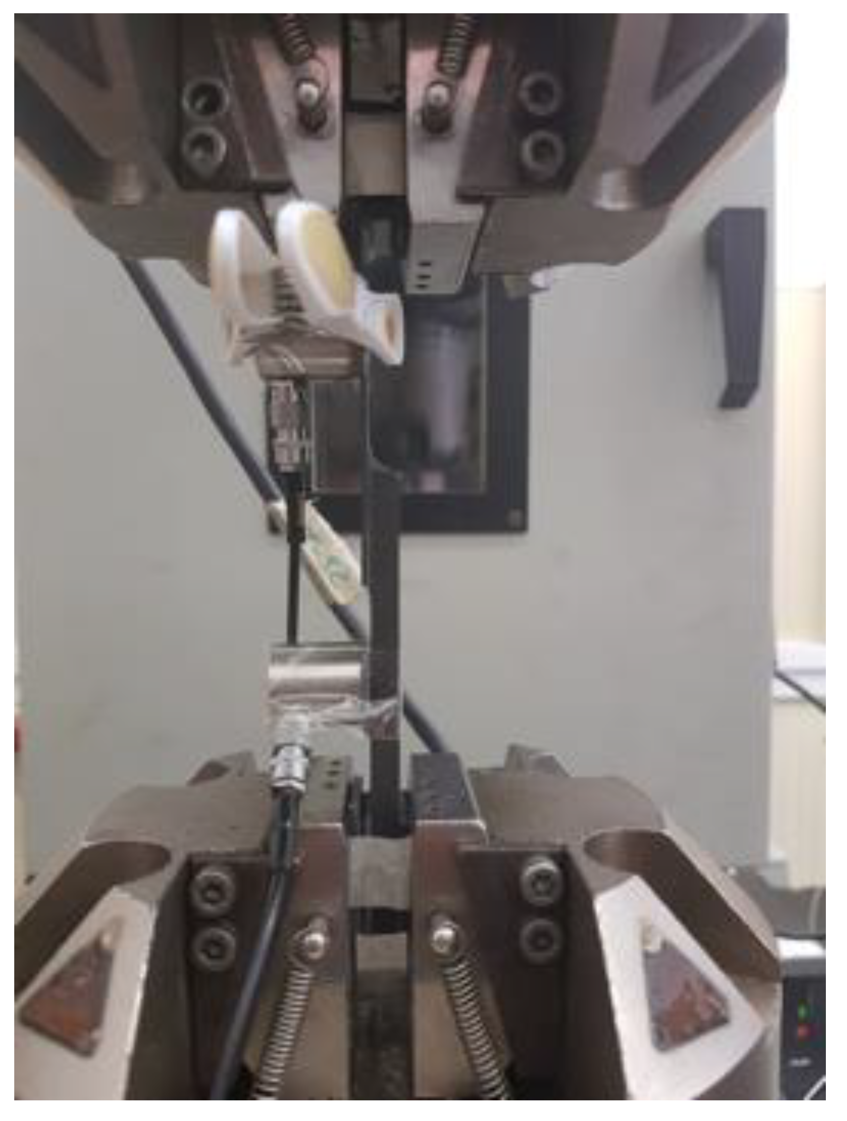
2.2. Testing Methods

The tension was applied to the specimens under displacement-controlled mode at a speed of 13 mm/min, in accordance with the ASTM D5868 standard and previous works presented in the literature [27,28]. Although the value of the strain rate suggested from the standard method is quite high, it does not significantly influence the mechanical response of the lap joints [29]. The test was carried out in the INSTRON servo-hydraulic testing machine with a maximum load capacity of 100 kN. To record the acoustic activities under loading, two narrow-band general purpose AE sensors were used: R30a (Physical Acoustics, MISTRAS Group, NJ, USA). The sensor has an operating range of 150 kHz to 400 kHz and a resonant frequency of 300 kHz. The reason for selecting the narrow band sensor is because in CFRPs, the recorded AE signals mostly are under the frequency band of 400 kHz. To avoid unnecessary noise, the narrow-band sensor was selected. For the same purpose, the sampling rate was set as 1 MSPS (mega samples per second). The threshold of AE acquisition was set at 35 dB and the recorded signals were amplified by 40 dB through a 2/4/6 AE (Acoustic Emission) preamplifier.
The sensors were placed at 40 mm either side from the centre of the adhesive overlapping region (Figure 3). Silica gel was interposed between the surface of the sensor and the specimens, in order to improve the coupling of the elements. This location was selected based on the length of the overlapping region and to record the AE signals produced within the overlapping region. As indicated in the previous section, the load is carried out only through the adhesives under displacement-controlled mode. For this reason, the AE signals recorded beyond the adhesive overlapping region are discarded. In the fractured specimen, not many damages were observed except in the area covering the overlapping adhesive layer. The surface of the specimen post rupture has been analysed by means of an optical microscope NIKON SMZ800. Moreover, the region of the adhesive and the fractured surfaces have also been studied after the shearing failure.
It is well known that the distance from the sensor to the acoustic source affects the propagation of the AE signals. This can result in the attenuation of the recorded AE signals. To avoid this attenuation, the AE sensors were calibrated for the attenuation in signal with respect to the distance from the sensor [30]. A pencil break test was performed, which normally produces a peak amplitude of 95 dB to 99 dB at varying distances from the sensor on the SLS and JLS specimens. The table of this calibration was then fed to the PAC PCI 2 data acquisition system, which automatically calibrated the attenuation of the signal.

2.3. Acoustic Emission (AE) Characterization

The recorded acoustic data used for this study are cumulative counts and cumulative energy. Counts are the number of instances of the recorded acoustic signal crosses the set threshold.
The acoustic energy is the total energy of the recorded acoustic event over the time period of the signal t0 to ti. If Ui is the transient voltage of the recorded acoustic event, then the acoustic energy EAE is given by Equation (1) [31]:
E A E = t 0 t i U i 2 ( t ) d t

3. Results and Discussions

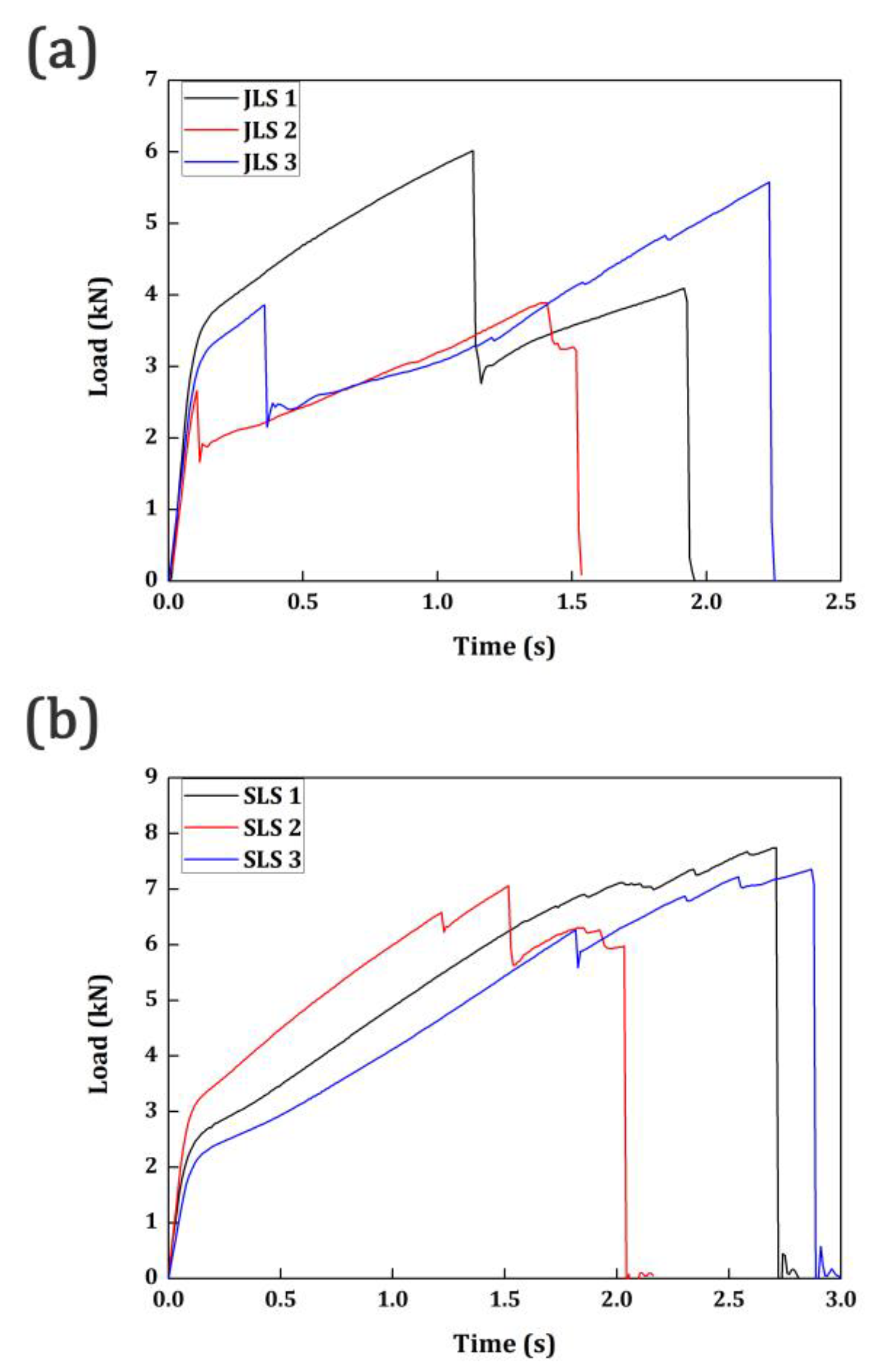
3.1. Mechanical Test Results

The bonding characteristics of the JLS and SLS specimens were tested by applying tensile load under displacement-controlled mode as per the ASTM D5868 standard. When the tensile load was applied, the entire load was distributed through the adhesive region. It has been reported by several researchers with solid evidences that the thickness of the adherend does not have a significant role in the distribution of load under shearing [26]. There could also be more than one peak load value, with each of them contributing to the damage characteristics or the bonding characteristics of the specimen.
Figure 4 shows the load vs. time curve for the specimens. In the research work presented, more than one peak can be observed in the load vs. time curve for both specimens. It must be noted that although there are several small peaks observed in both JLS and SLS specimens in Figure 4, the initial peak load is considered as the initial rupture point and the final peak load is considered as the final rupture point. Since these mechanical results provide only a limited amount of information on the damage characteristics, the acoustic emission results have been used in the subsequent sections. Table 3 shows the mechanical characteristics of both JLS and SLS specimens.
The first major observation from the mechanical test results is the varying peak load values of the same specimen group, both in JLS and SLS. This is common when it comes to the practice of adhesive bonded specimens [27,28,29] because the bond quality is not only determined by the curing characteristics, the thickness of the adhesive and other mechanical characteristics, but also on the efficiency of the user who handles the adhesives. The adhesives are normally mixed using a hand mixer rather than a mechanical controller owing to its high viscosity and requirements. Thus, it is inevitable that a considerable amount of difference can be observed between the adhesive bonded specimens of the same group. This is the reason why there is a difference in both the peak loads at initial and final ruptures and they are not similar between the same specimen group (refer to Figure 4 and Table 3). Furthermore, under this view, an increase in the number of test specimens would increase the accuracy of the evaluation of the scattering but it not will reduce the latter.
As indicated in the previous sections, the thickness of the adherend does not generally affect the strength of the adhesive bonded shear specimens under displacement-controlled mode. Nonetheless, the thickness of the adhesive carries the majority, if not all the load. In the SLS specimens, owing to their larger thickness than JLS specimens, higher peak loads are accounted for. The average peak load at the initial rupture in SLS specimens is 6.78 kN, while the JLS specimens have an average peak load of 4.18 kN. Similarly, at the final rupture stage, SLS specimens have an average peak load of 7.02 kN, while JLS specimens have 4.52 kN. In SLS specimens, the load is carried along the cross-sectional area of the adhesive region. However, in the JLS specimens, the shear strength of the specimen is also governed by the end curvature effect. This is explained by Taib et. al. [11] in their research work. Single lap joints, when loaded, transfer most of the load in shearing. Joggled lap joints, however, transfer most of the load in peeling. This is also the reason why the joggled lap joints have lower displacement when compared to the single lap joint specimens. The joggled joints suffer lateral deflections rather than shearing, which result in inducing high peel stress on the neutral axis. This results in the crack initiating at the joggled knee of the curvature region. This will result in low peak loads, which are observed in the present research work (see Table 3 and Figure 4). Similar results have been presented by Kishore and Prasad [32], who also addressed the effect of the eccentricity of the joggle in the strength of the joggled lap specimens. It has been addressed by both Taib et. al [32] and Kishore and Prasad [33] that the joggled lap specimens will have lower strength in comparison with the single lap joints. The same has been observed in the presented research work.

3.2. Acoustic Emission Results: Cumulative Counts and Cumulative Energy

The damage characteristics or the mode of failure in the adhesive bonded specimens cannot be explained through the mechanical characteristics. Furthermore, predicting the failure at an early stage is also not easy by studying only the mechanical characteristics. It can be explained by the acoustic emission characteristics. The load vs. time curve of the JLS specimens is plotted over the cumulative counts and the cumulative energy of the AE recorded. It is presented in Figure 5. Similarly, the SLS specimens are presented in Figure 6.
In Figure 5, it can be observed that whenever there is a load peak in the load vs. time curve in any of the JLS specimens, the cumulative counts and cumulative energy show a steep increase. The initial load drops in all JLS 1, JLS 2 and JLS 3 at 1.1 s, 0.1 s and 0.35 s, respectively, have been associated with the increase in cumulative counts and cumulative energy. Similarly, at the final stages of loading prior to failure 1.8 s, 1.35 s and 2.25 s, respectively, for JLS 1, JLS 2 and JLS 3 are also associated with the increase in cumulative counts and energy. However, there are some instances, particularly around 1.2 s in the JLS 2 specimen, where the cumulative counts and energy increased unexpectedly without any change in the load vs. time curve. This phenomenon could not be explained without utilizing another characterizing technique or a deeper investigation like the frequency content of the acoustic data. Nonetheless, analysing the waveform of those signals in their time-frequency domain can also provide information about whether these signals are representatives of machine or surrounding noises. This is not the only information that can be obtained from the AE results. In JLS 1 specimen, the cumulative energy increases steeply around 1.1 s duration and it remains almost constant until the specimen reaches its final rupture region. Nonetheless, the cumulative counts kept increasing gradually beyond the 1.1 s duration and the slope took a steep increase as the material reaches failure. This means that a large number of counts have been recorded with very low energy from 1.1 s duration to the final failure. In a non-linear material, such as plastics or composite materials, the large counts with low energy represent the matrix cracking. The ratio between the cumulative energy and the cumulative count varies at different damage modes in a material. When this ratio exhibits a very low value, it can be said that the energy is low with large counts. On that basis, this can be attributed to the matrix cracking. Brittle fractures such as interlaminar crack growth and fiber breakage release large energy acoustic events, which are responsible for the initial and final ruptures. Between the stages of the initial failure and the final failure in the JLS 1 specimen, the material has experienced only matrix cracking. This indicates that shearing has occurred in the adhesive region rather than peeling which attributes to the low-energy acoustic events. This indicates that the JLS 1 specimen has carried more load before failure than the JLS 2 and JLS 3 specimens due to the shearing mode of failure. This could be one of the reasons why the JLS 1 specimen has a higher peak load when compared to JLS 2 and JLS 3.
In the cases of JLS 2 and JLS 3, they have similar load vs. time, cumulative counts and energy patterns. Both these specimens experienced the initial rupture at a very early stage, 0.1 s for JLS 2 and 0.35 s for JLS 3. The cumulative counts and energy have also increased steeply at these time periods. Beyond that point, the cumulative counts and the cumulative energy increase almost linearly with one another. This represents the delamination in the adhesive bonded region. The adhesive peeling is occurring at this stage, which is the reason for the simultaneous increase in the counts and energy. While reaching the final stage of failure, JLS 2 and JLS 3 have probably experienced fiber breakage which is indicated by the sudden increase in counts and energy near the final rupture region.
While looking at Figure 6, all the three specimens have almost similar patterns in terms of load vs. time, cumulative counts and energy. However, the simultaneous increase in the counts and energy of the SLS specimens must not be compared or to be confused with the JLS specimens. Although in both the cases the cumulative counts and cumulative energy increased linearly, the slope of the increment is entirely different. The slope of the increment in SLS specimens is higher than the JLS specimens. Therefore, they do not represent the same damage mode although it looks similar. In the SLS specimens, the cumulative counts and energy are very low during the initial stages of loading until the specimens have suffered their initial rupture. In the SLS specimens, most of the load is distributed in shearing and these low-energy and low-count AE signals indicate the shearing occurring in the adhesive region. AE signals connecting to fiber breakages and transverse cracks growth release acoustic data with higher energy and lower counts, owing to their lower order symmetric nature. Since the energy and counts recorded are low during these stages, these signals are higher order asymmetric in nature that could be connected only to shearing phenomena [20]. Beyond the region of the initial rupture, in all three SLS specimens, the cumulative counts and energy start to increase simultaneously until they reach the final failure. This indicates that the cumulative counts and energy were very low until the crack opens in the adhesive. Generally, the crack openFs at the adhesive and adherend interface, which is governed by the geometry of the overlapping area. Once the crack had opened, due to the brittle nature of the adhesive, it progressed faster through the thickness of the adhesive. This interlaminar crack growth always generates higher counts and higher energy. This pattern continued until the specimens failed at the final rupture.

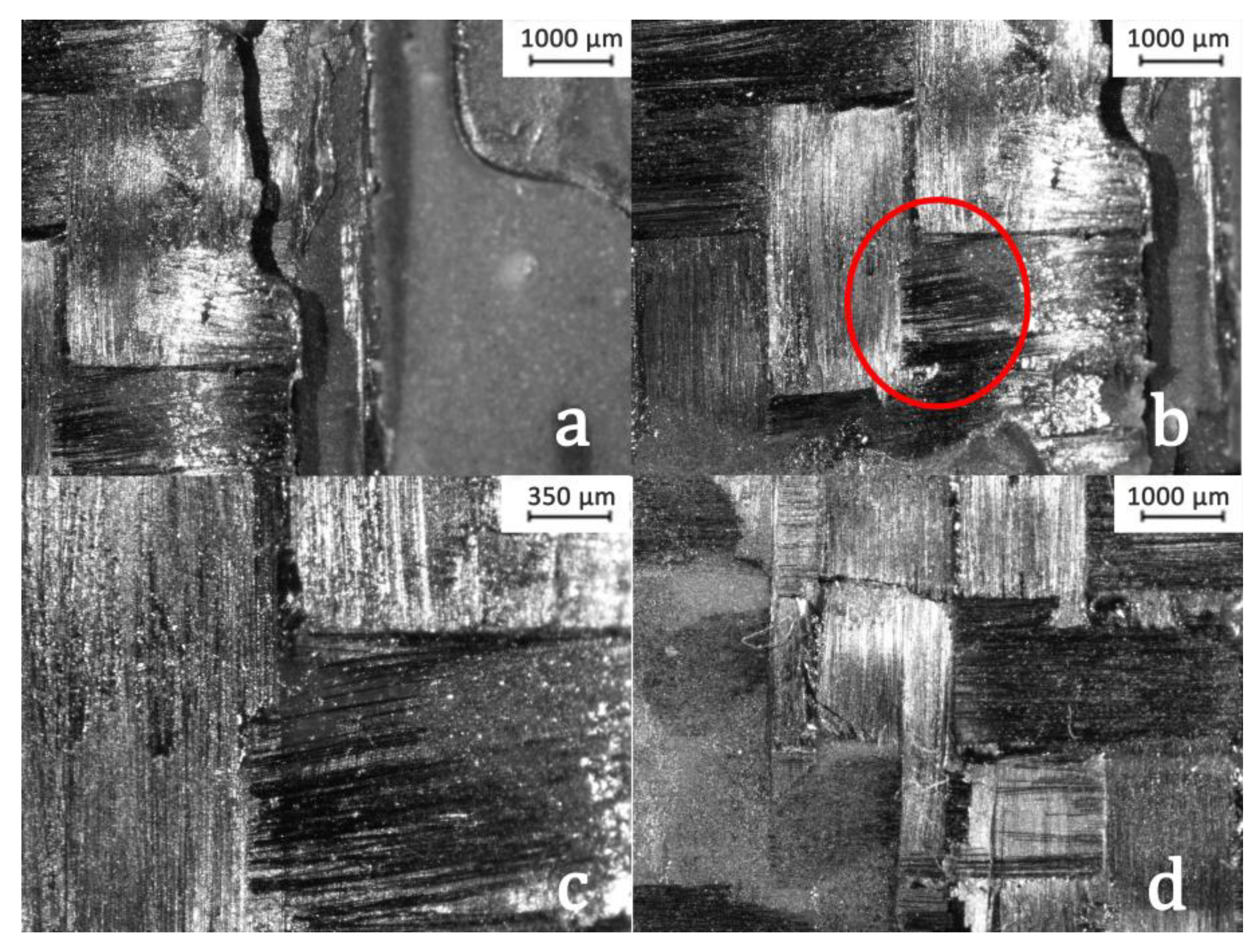
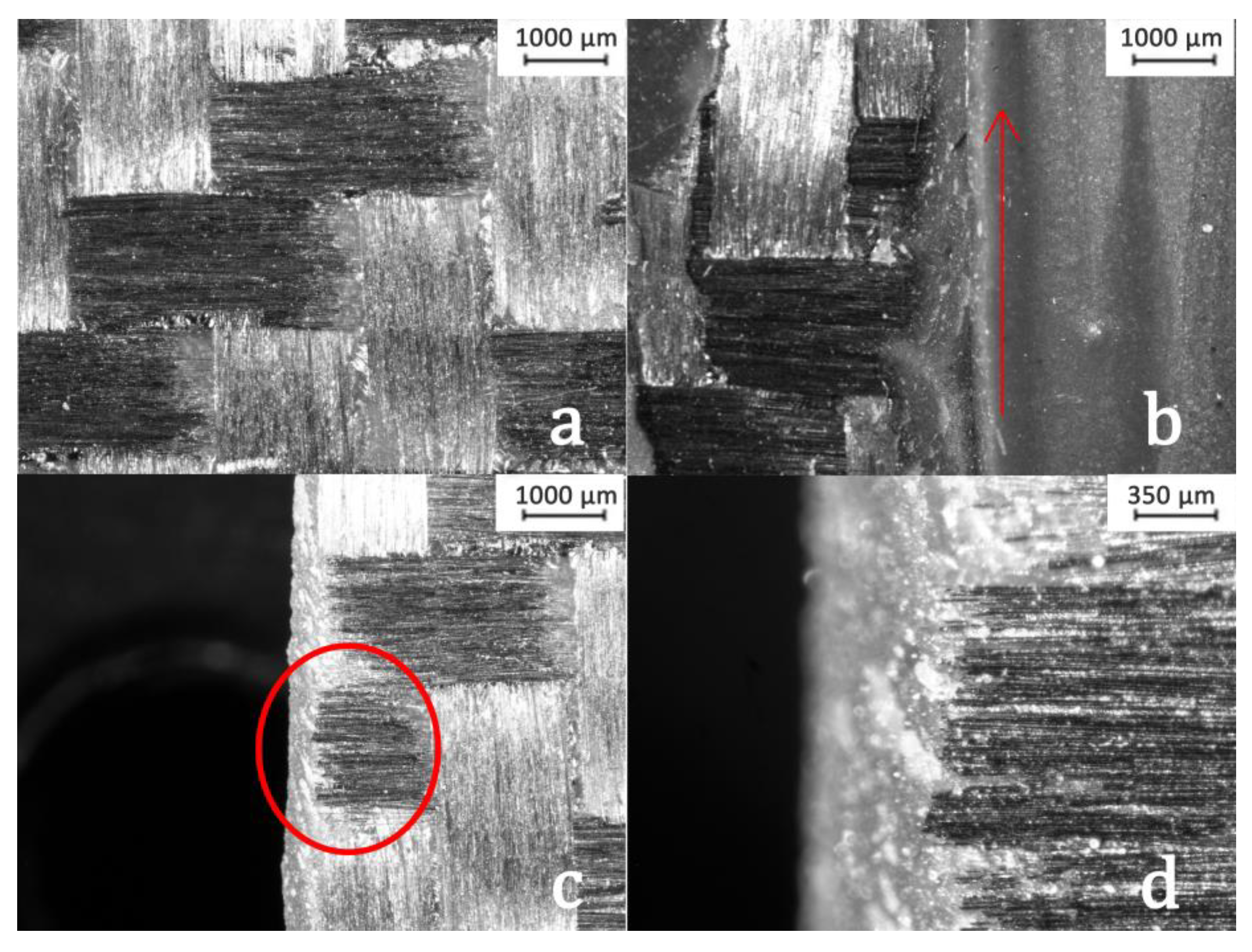
3.3. Fracture Surface Analysis

To confirm the brittle failure of the adhesives in the SLS specimens and to identify the peeling and fiber breakage failure in JLS specimens, the fractured surfaces were observed under optical microscope. The fractographic results of specimen JLS is presented in Figure 7.
In Figure 7a, the adhesive layer peeling off at the knee of the curvature in the joggled overlapping region can be observed. The debonding of the laminates along the applied adhesive layers can be viewed in Figure 7b. The adhesive not only peeled off from the lamina but also inflicted fiber/matrix debonding in the same lamina. Figure 7c is the zoomed view of the circled region in Figure 7b. From Figure 7c, the ruptured fiber at the end of the lamina can be observed. Figure 7d shows the presence of more fiber/matrix debonding and fiber breakage near the knee of the adhesive joint. This consolidates the explanations provided in Section 3.2 regarding the failure modes by acoustic emission parameters.
Similarly, the optical images of SLS specimens are presented in Figure 8. Figure 8a shows the complete lack of matrix/fiber debonding in the area where the adhesive is applied. The fibers are left unharmed in the fractured region of the adhesive. The adhesive has delaminated from the outermost ply, but it did not affect the fiber/matrix integrity. Figure 8b shows the brittle fracture and the direction of the crack grew along the width of the adhesive under loading. Figure 8c shows the fiber breakage at the end of the specimen. Figure 8d is the zoomed image of the ruptured fibers. So, the fiber breakage has occurred in the SLS specimens, nonetheless, only at the edge of the lamina.
Therefore, by comparing Figure 7 and Figure 8, it can be concluded that the crack growth initiated at the knee of the joggled lap in the JLS specimens, which in turn results in the peeling. The peeling also has induced the debonding between the fiber and matrix in the area where the adhesive is applied. However, in SLS specimens, the crack opened in the adhesive region and travelled through the width of the specimen resulting in a brittle failure.
The fractographic results are sufficient to prove the damage modes explained in the acoustic emission result sections. Thus, the AE proves to be a powerful tool, not only in predicting the failure in an adhesive bonded FRP but also in identifying the different damage modes in the failure. By setting up a proper experimental campaign and understanding the different AE descriptors, it is efficient to analyse the failure modes in an entire structure comprising adhesive-bonded FRP.

4. Conclusions

The bonding characteristics of adhesive-bonded FRP specimens were tested using the acoustic emission technique. The differences in the failure mechanisms were observed by comparing the cumulative counts and cumulative energy under loading. The slope of the cumulative counts and energy were different in JLS and SLS specimens indicating that both the specimen groups failed under different damage modes. Moreover, the cumulative energy and cumulative counts can provide information on the critical points of failure. In the joggled-lap specimens, the initial failure was due to the peeling of the adhesive layer at the knee of the curvature region and it induced the fiber/matrix debonding. The final failure was due to the fiber breakage in the lamina. In the single-lap specimens, the initial failure was due to the crack opening of the adhesive and the crack propagated through the width of the adhesive resulting in the final failure. The explanations provided by the AE results were evidentially proved by the fractographic analysis of the specimens. Acoustic emission proves to be a powerful tool in analysing the damage characteristics of fiber-reinforced plastics.

Author Contributions

Conceptualization, P.K.V. and C.B.; methodology, P.K.V., C.B. and V.M.; validation, C.B. and P.K.V.; formal analysis, P.K.V. and C.B.; investigation, P.K.V. and C.B.; data curation, C.B., V.M. and P.K.V.; writing—original draft preparation, P.K.V.; writing—review and editing, P.K.V. and C.B.; supervision, C.C. and C.P.; project administration, C.C. and C.P. All authors have read and agreed to the published version of the manuscript.

Funding

This research received no external funding.

Conflicts of Interest

The authors declare no conflict of interest.

References

  1. Sugita, Y.; Winkelmann, C.; La Saponara, V. Environmental and chemical degradation of carbon/epoxy lap joints for aerospace applications, and effects on their mechanical performance. Compos. Sci. Technol. 2010, 70, 829–839. [Google Scholar] [CrossRef]
  2. Campilho, R.D.S.G.; de Moura, M.F.S.F.; Domingues, J.J.M.S. Using a cohesive damage model to predict the tensile behaviour of CFRP single-strap repairs. Int. J. Solids Struct. 2008, 45, 1497–1512. [Google Scholar] [CrossRef]
  3. Yu, Q.; Gao, R.; Gu, X.; Zhao, X.; Chen, T. Bond behavior of CFRP-steel double-lap joints exposed to marine atmosphere and fatigue loading. Eng. Struct. 2018, 15, 76–85. [Google Scholar] [CrossRef]
  4. Kucher, N.K.; Zemtsov, M.P.; Zarazovskii, M.N. Deformation behavior and strength of unidirectional carbon fiber laminates. Mech. Compos. Mater. 2006, 42, 407–418. [Google Scholar] [CrossRef]
  5. Tong, L.; Steven, G.P. Analysis and Design of Structural Bonded Joints; Kluwer Academic Publishers: Boston, MA, USA, 1999. [Google Scholar]
  6. Barile, C.; Casavola, C.; Gambino, B.; Mellone, A.; Spagnolo, M. Mode-I fracture behavior of CFRPs: Numerical model of the experimental results. Materials 2019, 12, 513. [Google Scholar] [CrossRef] [PubMed] [Green Version]
  7. Benatar, A.; Gillespie, J., Jr.; Kedward, K. Joining of composites. In Advanced Composites Manufacturing; Gutowski, T.G., Ed.; John Wiley: New York, NY, USA, 1997; pp. 487–512. [Google Scholar]
  8. Jones, R.M. Mechanics of Composite Materials, 2nd ed.; Taylor and Francis Publishers: New York, NY, USA, 1999. [Google Scholar]
  9. Barile, C.; Casavola, C.; Pappalettera, G.; Vimalathithan, P.K. Characterization of adhesive bonded CFRP laminates using full-field digital image stereo-correlation and finite element analysis. Compos. Sci. Technol. 2019, 169, 16–25. [Google Scholar] [CrossRef]
  10. Li, G.; Pang, S.S.; Woldesenbet, E.; Stubblefield, M.A.; Mensah, P.F.; Iberkwe, S.I. Investigation of prepreg bonded composite single lap joint. Compos. Part B Eng. 2001, 32, 651–658. [Google Scholar] [CrossRef]
  11. Taib, A.A.; Boukhili, R.; Achiou, S.; Gordon, S.; Boukehili, H. Bonded joints with composite adherends. Part I. Effect of specimen configuration, adhesive thickness, spew filler and adherend stiffness on fracture. Int. J. Adhes. Adhes. 2006, 26, 226–236. [Google Scholar] [CrossRef]
  12. Yang, C.; Tomblin, J.S. Investigation of Adhesive Behavior in Aircraft Applications; DOT/FAA/AR-01/57; US Department of Transportation Federal Aviation Administration, Office of Aviation Research: Washington, DC, USA, 2001.
  13. Grosse, C. Introduction. In Acoustic Emission Testing; Grosse, C., Ohtsu, M., Eds.; Springer: Berlin/Heidelberg, Germany, 2008. [Google Scholar]
  14. Balázs, G.L.; Grosse, C.; Koch, R.; Reinhardt, H.W. Damage accumulation on deformed steel bar to concrete interaction detected by acoustic emission technique. Mag. Concr. Res. 1996, 48, 311–320. [Google Scholar] [CrossRef]
  15. Grosse, C.; Linzer, L. Signal-based AE analysis. In Acoustic Emission Testing; Grosse, C., Ohtsu, M., Eds.; Springer: Berlin/Heidelberg, Germany, 2008. [Google Scholar]
  16. Barile, C.; Casavola, C.; Pappalettera, G. Acoustic emission waveform analysis in CFRP under Mode I test. Eng. Fract. Mech. 2018, 210, 408–413. [Google Scholar] [CrossRef]
  17. Barile, C.; Casavola, C.; Pappalettera, G.; Vimalathithan, P.K. Damage characterization in composite materials using acoustic emission signal-based and parameter-based data. Compos. Part B-Eng. 2019. [Google Scholar] [CrossRef]
  18. Barile, C.; Casavola, C.; Pappalettera, G.; Vimalathithan, P.K. Investigation of structural integrity of composite materials using wavelet packet transform. Procedia Eng. 2019, 17, 582–588. [Google Scholar] [CrossRef]
  19. Hamstad, M.A. Frequencies and Amplitudes of AE Signals in a Plate as a Function of Source Rise Time. In Proceedings of the 29th European Conference on Acoustic Emission Testing; Available online: https://www.ndt.net/events/EWGAE%202010/proceedings/papers/20_Hamstad.pdf (accessed on 4 March 2020).
  20. Oz, F.E.; Ersoy, N.; Lomov, S.V. Do high frequency acoustic emission events always represent fibre failure in CFRP laminates? Compos. Part A Appl. Sci. 2017, 103, 230–235. [Google Scholar] [CrossRef]
  21. Liu, P.F.; Chu, J.K.; Liu, Y.L.; Zheng, J.Y. A study on the failure mechanisms of carbon fiber/epoxy composite laminates using acoustic emission. Mater. Design 2012, 37, 228–235. [Google Scholar] [CrossRef]
  22. De Groot, P.J.; Wijnen, P.A.M.; Janssen, R.B.F. Real-time frequency determination of acoustic emission for different fracture mechanisms in carbon/epoxy composites. Compos. Sci. Technol. 1995, 55, 405–412. [Google Scholar] [CrossRef]
  23. Njuhovic, E.; Bräu, M.; Wolff-Fabris, F.; Starzynski, K.; Altstädt, V. Identification of failure mechanisms of metallised glass fibre reinforced composites under tensile loading using acoustic emission analysis. Compos. Part B-Eng. 2015, 81, 1–13. [Google Scholar] [CrossRef]
  24. Alia, A.; Fantozzi, G.; Godin, N.; Osmani, H.; Reynaud, P. Mechanical behaviour of jute fibre-reinforced polyester composite: Characterization of damage mechanisms using acoustic emission and microstructural observations. J. Compos. Mater. 2019. [Google Scholar] [CrossRef]
  25. ASTM D5868-01(2014). Standard Test Method for Lap Shear Adhesion for Fiber Reinforced Plastic (FRP) Bonding; ASTM International: West Conshohocken, PA, USA, 2014; Available online: www.astm.org (accessed on 4 March 2020).
  26. Mangalgiri, P.D.; Johnson, W.S.; Everett, R.A., Jr. Effect of adherend thickness and mixed mode loading on debond growth in adhesively bonded composite joints. J. Adhes. 1987, 23, 263–288. [Google Scholar] [CrossRef]
  27. Hsiao, K.T.; Alms, J.; Advani, S.G. Use of epoxy/multiwalled carbon nanotubes as adhesives to join graphite fibre reinforced polymer composites. Nanotechnology 2003, 14, 791–793. [Google Scholar] [CrossRef]
  28. Avila, A.F.; Bueno, P.O. An experimental and numerical study on adhesive joints for composites. Compos. Struct. 2004, 64, 531–537. [Google Scholar] [CrossRef]
  29. Liu, X.; Shao, X.; Li, Q.; Sun, G. Experimental study on residual properties of carbon fibre reinforced plastic (CFRP) and aluminum single-lap adhesive joints at different strain rates after transverse pre-impact. Compos. Part A Appl. Sci. Manuf. 2019, 124, 105372. [Google Scholar] [CrossRef]
  30. Finkel, P.; Mitchell, J.R.; Carlos, M.F. Experimental study of ‘Auto Sensor Test-Self Test Mode’ for acoustic emission system performance verification. AIP. Conf. Proc. 2000, 509, 1995–2002. [Google Scholar]
  31. Harris, D.O.; Bell, R.L. The measurement and significance of energy in acoustic-emission testing. Exp. Mech. 1977, 17, 347–353. [Google Scholar] [CrossRef]
  32. Kishore, A.N.; Prasad, N.S. An experimental study of Flat-Joggle-Flat bonded joints in composite laminates. Int. J. Adhes. Adhes. 2012, 35, 55–58. [Google Scholar] [CrossRef]
  33. Taib, A.A.; Boukhili, R.; Achiou, S.; Boukhili, H. Bonded joints with composite adherends. Part II. Finite element analysis of joggle lap joints. Int. J. Adhes. Adhes. 2006, 26, 237–248. [Google Scholar] [CrossRef]
Figure 1. Single-lap shear (SLS) (a) and joggled-lap shear (JLS) (b) specimens’ nominal dimensions.
Applsci 10 01782 g001
Figure 2. (a) SLS specimen, (b) joint overlap of SLS specimen, (c) JLS specimen, (d) joint overlap of JLS specimen.
Applsci 10 01782 g002
Figure 3. Testing rig with acoustic emission (AE) sensors mounted on the specimen.
Applsci 10 01782 g003
Figure 4. Load vs. time curve: (a) JLS Specimens; (b) SLS Specimens.
Applsci 10 01782 g004
Figure 5. Load, cumulative counts, cumulative energy vs. time: (a) JLS 1; (b) JLS 2; (c) JLS 3.
Applsci 10 01782 g005
Figure 6. Load, cumulative counts, cumulative energy vs. time: (a) SLS 1; (b) SLS 2; (c) SLS 3.
Applsci 10 01782 g006
Figure 7. Fractographic analysis of JLS specimens. (a) Peeling at the knee of adhesive; (b) Debonding of laminates; (c) Ruptured Fiber; (d) Fiber/Matric Debonding.
Applsci 10 01782 g007
Figure 8. Fractographic analysis of SLS specimens. (a) Lack of Fiber/Matrix debonding; (b) Direction of cracking growth along the length of adhesive; (c) Fiber breakage; (d) Close in view of fiber breakage.
Applsci 10 01782 g008
Table 1. JLS specimens’ geometry and characteristics.
Flat Adherend
Length (mm)Width (mm)Thickness (mm)No. of PliesStacking sequence
101.6 ± 0.1226.09 ± 0.072.0 ± 0.048[+45/−45]3/−45/+45
Curved Adherend
Length (mm)Width (mm)Thickness (mm)No. of PliesStacking sequence
101.6 ± 0.1726.09 ± 0.051.5 ± 0.026[+45/+45/−45]S
Overlapping Region (Adhesive)
Length (mm)Width (mm)Thickness (mm)
26 ± 0.2126.09 ± 0.063.67 ± 0.05
Table 2. SLS specimens’ geometry and characteristics.
Upper Adherend
Length (mm)Width (mm)Thickness (mm)No. of PliesStacking sequence
101.6 ± 0.1125.33 ± 0.121.3 ± 0.055+45/+45/+45/−45/+45
Lower Adherend
Length (mm)Width (mm)Thickness (mm)No. of PliesStacking sequence
101.6 ± 0.0925.33 ± 0.146.4 ± 0.1226 +45/[+45/−45]12/+45
Overlapping Region (Adhesive)
Length (mm)Width (mm)Thickness (mm)
26 ± 0.1225.33 ± 0.258.5 ± 0.11
Table 3. Damage characteristics in JLS and SLS specimens.
SpecimenPeak Load (kN)
Initial RuptureFinal Rupture
JLS 16.024.09
JLS 22.673.89
JLS 33.865.57
Mean4.184.52
Std. Dev.1.700.92
SLS 17.057.75
SLS 27.065.96
SLS 35.937.36
Mean6.787.02
Std. Dev.0.750.94

