Effect of Local Gas Flow in Full Penetration Laser Beam Welding with High Welding Speeds


1
Production Technology Group, Technische Universität Ilmenau, Gustav-Kirchhoff-Platz 2, 98693 Ilmenau, Germany
2
Department of Quality Assurance and Industrial Image Processing, Technische Universität Ilmenau, Gustav-Kirchhoff-Platz 2, 98693 Ilmenau, Germany
*
Author to whom correspondence should be addressed.
Appl. Sci. 2020, 10(5), 1867; https://doi.org/10.3390/app10051867
Submission received: 18 February 2020
/
Revised: 4 March 2020
/
Accepted: 5 March 2020
/
Published: 9 March 2020
(This article belongs to the Special Issue Model of Laser Welding)
Abstract
:Spatter formation is a major issue in deep penetration welding with solid-state lasers at high welding speeds above 8 m/min. In order to limit spatter formation, the use of local gas flows represents a technically feasible solution. By using the gas flow, the pressure balance inside the keyhole, and therefore the keyhole stability, is affected. Existing investigations demonstrate a reduction in spatter and pore formation for partial penetration welding up to a welding speed of 5 m/min. However, the effect of the gas flow is not yet clarified for full penetration welding at welding speeds above 8 m/min. By using a precisely adjustable shielding gas supply, the effect of a local gas flow of argon was characterized by welding stainless steel AISI304 (1.4301/X5CrNi18-10). The influence of the gas flow on the melt pool dynamics and spatter formation was recorded by means of high-speed videography and subsequently analyzed by image processing. Schlieren videography was used to visualize the forming flow flied. By the use of the gas, a change in melt pool dynamics and gas flow conditions was observed, correlating to a reduction in loss of mass up to 70%. Based on the investigations, a model of the acting effect mechanism was given.
1. Introduction
New developments in the field of solid-state lasers has led to the availability of higher power classes at relatively low investment costs. These power classes offer the potential to significantly increase the processing speed in various applications result in a considerable improvement of economic efficiency. However, the potential cannot yet be utilized for laser beam welding of high-alloyed steels. When welding with high welding speeds ≥8 m/min, process instabilities occur, which negatively affect welding quality [1]. In this context, spatter formation must be particularly emphasized as the loss of mass results in adhering spatters as well as in affected mechanical properties. The process of spatter formation can be attributed to two basic mechanisms [1,2,3,4]. The first mechanism is significant for welding speeds up to approx. 8 m/min and assumes that the spatter detachment takes place within the keyhole. While the keyhole is characterized by the formation of steps on the front and the rear side of the keyhole wall, the escaping metal vapor interacts with the molten material [5]. Based on the windage of the steps, an impulse is transferred from the escaping metal vapor to the molten material. As a result, spatters can be detached in undirected spatter trajectories. When increasing the welding speed beyond 8 m/min, the key mechanism in spatter formation changes. According to the increase in keyhole inclination at high welding speeds, the energy absorption at the keyhole front is rising [3]. As a result, the metal vapor flow induced is directed towards the keyhole rear wall. Based on the interaction of the metal vapor and the rear wall, the melt pool fluctuates and starts to move along welding direction. If the transferred impulse exceeds a critical threshold, spatter formation occurs [4,6,7]. This relation can be given by the condition of spatter formation (Equation (1)). For the extraction of one single spatter, the kinetic energy of the fluid element in the melt (Ekin,fl) must be greater than the sum of the kinetic energy of the droplet (Ekin,dr) and the surface energy of the melt (Esurf,fl) [8,9].
Another representation of this relation can be given based on droplet volume Vdr, velocity of the fluid element vfl, velocity of the droplet vdr, surface tension σ, and surface area of the droplet Odr (Equation (2)) [8].
However, the formation of spatters depends significantly on the stability of the keyhole, which can be derived by the pressure balance inside the keyhole (Equation (3)) [10,11]. Thereby, the equilibrium includes the physical quantities of the recoil pressure pabl, differential vapor pressure pdp_v, atmospheric pressure p0, surface tension pressure pσ, hydrostatic pressure ph and hydrodynamic pressure pdyn. Following this, the equilibrium gives the relation of the opening pressures to the closing pressures of the keyhole.
In order to form a stable and less fluctuating keyhole, the opening pressures must be at least equal or greater than the closing pressures of the keyhole [12]. In this context, numerous parameters have been investigated for manipulating the pressure balance. Despite solutions using laser beam shaping [13,14,15,16], power modulation [17,18], or vacuum systems [19,20], the use of local gas flows represents a technically feasible solution. By using the gas flow, the pressure balance is affected by an additionally exerted dynamic pressure depending on the density ρgas and the flow velocity vgas of the supplied gas (Equation (4)) [21]. As a result, the opening pressures are amplified by the relative dynamic pressure . Besides the general pressure increase, a compressive force is also exerted in the field of interaction.
The effect of a lateral shielding gas flow at deep penetration laser beam welding of 1.4301 (X5CrNi18-10, AISI304) at a welding speed of 1 m/min was characterized by [22]. By using the gas flow, a reduced number of pores as well as a decreasing spatter formation could be determined. Based on a high flow rate of 20.4 L/min, an enlargement of the keyhole aperture was observed. Thereby, the change in the outgassing conditions of the metal vapor flow was stated as the reason for the spatter reduction. Further investigations gained comparable results for welding speeds up to 5 m/min [23]. By varying the flow orientation (leading and trailing positioning), no effect on the welding process could be noticed. In contrast, a positive effect of a trailing flow orientation was shown in [24], which was attributed to a reduced interaction of the gas flow with the outgassing metal vapor flow. Latest findings are proving a stabilizing effect on the keyhole formation for welding of martensitic steel in lap joints at a welding speed of 1.5 m/min [25]. By further investigations, the effect of a local gas supply was simulated by using computational fluid dynamics numerical analysis. According to the experimental investigations, an enlargement of the keyhole could also be observed [26]. Moreover, using the gas flow, the flow pattern in the rear-sided melt pool was characterized by less recirculation. The more uniform melt propagation results in an elongation of the melt pool [27]. Depending on flow rate, a reduction in keyhole fluctuations could be noticed also. Furthermore, simulations for deep penetration welding of aluminum AA 5083 could figure out a destabilizing effect of a leading flow orientation [28]. Thereby, the effect was attributed to an increasing upward momentum of the molten material.
However, the investigations have been carried out up to a welding speed of 5 m/min. A study about the influence of a local gas flow at welding speeds above 5 m/min has not been sufficiently investigated so far. Based on the latest investigations on partial penetration welding [29,30], this publication focusses on the influence of local gas flows on full penetration welding of high-alloy steel AISI304 (1.4301, X5CrNi18-10) at welding speeds from 8 m/min to 16 m/min. For this purpose, a novel experimental setup was developed, in order to characterize the effect of the gas flow on the stability of the keyhole and melt pool dynamics. Depending on flow rate, the influence of an affected pressure balance was investigated regarding the gas flow conditions as well as the change in spatter formation. Finally, the results are condensed in a description of the acting effect mechanism.
2. Materials and Methods
The experimental procedure was carried out for full penetration laser welding of stainless austenitic steel 1.4301 (X5CrNi18-10, AISI 304). The essential chemical composition of the steel is given in Table 1 below.
The bead-on-plate welding process was operated by using an orthogonally arranged disk laser (TruDisk 5000.75, Trumpf Laser und Systemtechnik GmbH, Ditzingen, Germany) which was equipped with a stationary welding optics (Figure 1a). The specifications of the laser system are shown in Table 2 below. The laser power was determined and set for a full penetration process regime, whereby the keyhole is fully penetrating the bottom side of the specimen. The specimens (150 × 40 × 2 mm) were clamped (clamping force of 295 N) at the front of a six-axis robot (KR 60HA, Kuka AG, Augsburg, Germany) which have been used for the handling process.
The experiments were recorded by means of a Photron SA-X2 high-speed camera (10.000 frames per second) which was equipped with a Navitar zoom lens. For a more detailed sight on the effect of the gas flow, the camera was arranged in three different positions (top view (60°), plane-parallel (0°) and bottom view (−60°)). To mask out process emissions, a narrow-band filter with a center wavelength of 808 nm was placed in front of the camera. During the top side and bottom side recording, the process was illuminated using a Cavitar Cavilux laser system (808 nm). In 0° orientation, the process was recorded based on thermal radiation in order to illustrate the spatter detachment more specific. Subsequently, the captured data were processed using a Matlab-based image analysis. Thereby, it was possible to determine the trajectories of spatter formation (superposition of 250 sequential frames) as well as the angle of detachment and the speed of each spatter. Besides the recordings based on thermal radiation, the Schlieren technique was used in the plane-parallel (0°) camera orientation. Based on the difference in density and in the refractive index of the supplied gas and the surrounding atmosphere, it was possible to visualize the forming flow pattern. Figure 1b shows a visualized flow pattern of helium, whereby the gas was used exemplary for illustration reasons due the high difference in density. Otherwise, the experiments were carried out using argon, to ensure comparable test conditions to preliminary investigations [29,30]. Further details in schlieren imaging are given in [31]. To quantify the effect of spatter formation, the resulting loss of material was weighed by using a high-precision balance (Kern PLJ 2000-3A, Balingen-Frommern, Germany). Therefore, the mass of the specimens was determined before and after the welding process, based on a seam length of 150 mm.
For the local supply of the gas, the setup was equipped with a nozzle unit (Figure 1c). A three-dimensional positioning of the nozzle was realized by three linear guides and one rotary disk. In this way, the system could be positioned with an accuracy of 0.05 mm and a reproducibility of 0.02 mm. Based on the findings of preliminary investigations [29,30], the nozzle was set to a trailing flow orientation with an angle of incidence of α = 48, while these settings resulted in the maximum reduction of loss of mass. This should ensure a direct interaction of the gas flow and the keyhole rear wall. Moreover, the unit was equipped with a coaxial alignment laser, which allowed the marking of the interaction area between the gas flow and the specimen. The nozzle tube of the unit had an inner diameter of 1.2 mm and were positioned in a constant distance from the nozzle tip to the specimen surface of 5 mm. All experiments were repeated for three times for statistical purposes. The error bars depicted in all graphs represent the standard deviation.
3. Results
3.1. Reference Process
In the first step, the welding process was characterized without gas supply (reference process). For this purpose, the resulting loss of mass was measured and analyzed by means of high-speed videography (Figure 2).
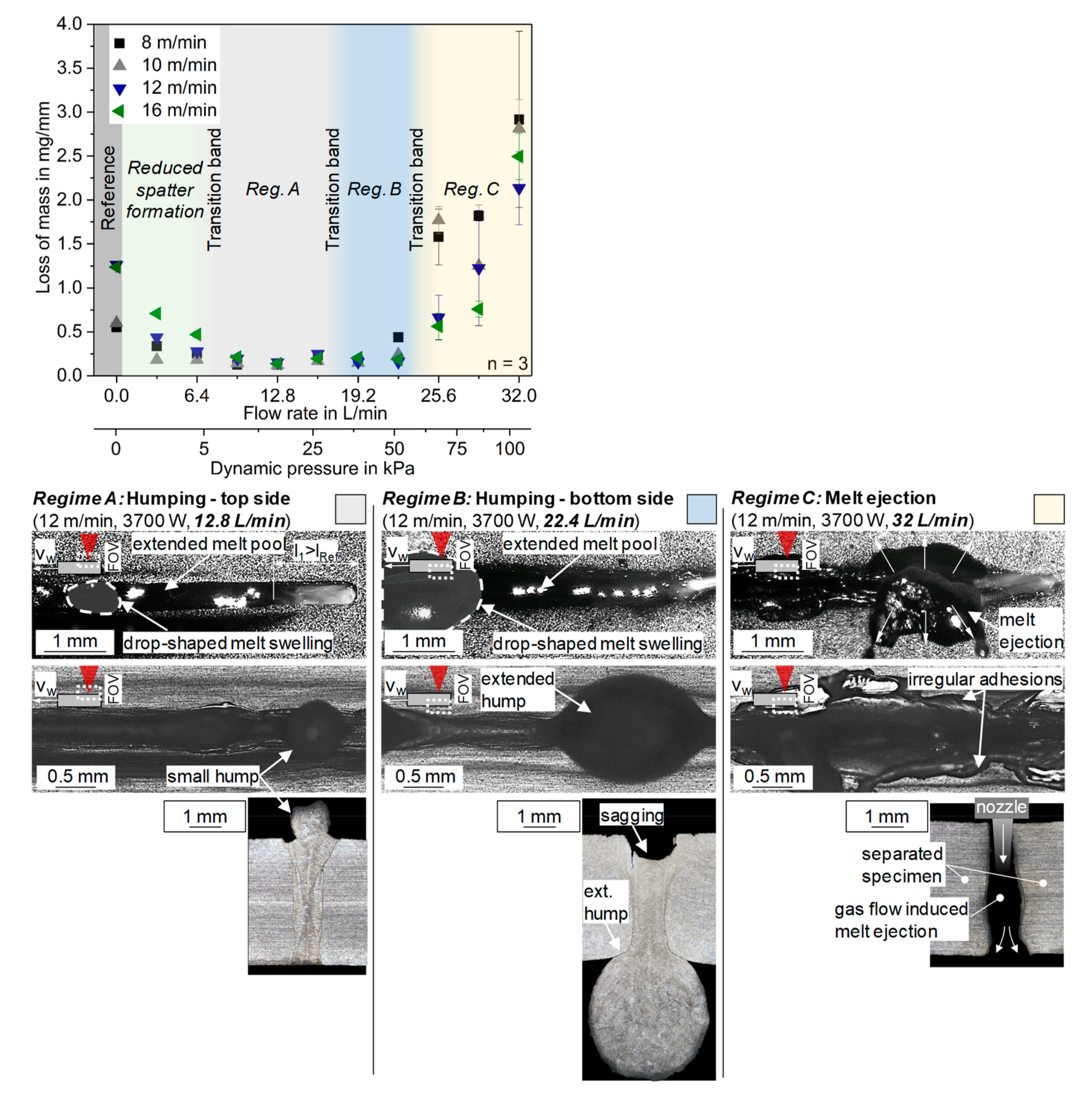
At a welding speed of 8 m/min, the lowest loss of mass of 0.56 mg/mm ± 0.01 mg/mm could be determined. Based on the high-speed recordings, a stable and slightly fluctuating keyhole was observed. The aperture of the keyhole formed circularly and was surrounded by a bead of melt. The rear side of the keyhole was characterized by the formation of a small melt pool swelling. However, this melt accumulation does not contribute to spatter formation. Instead, the spatter separation takes place inside the keyhole. Subsequently, the spatters were already detached from the melt pool within the keyhole wall. This resulted in the formation of small spatters, which were detached from the keyhole in undirected trajectories. In literature, this process regime is well known as “Rosenthal regime” [4]. High-speed recordings of the bottom side showed similar melt pool dynamics as well as a similar spatter formation mechanism as seen on the top side before. The weld seam on the top side was characterized by small adhering spatters, while the bottom side showed no adhering spatter. By increasing the welding speed to 10 m/min and 12 m/min, the melt pool dynamics changed. Following, the keyhole was fluctuating stronger, while a melt pool swelling was formed at the upper side of the keyhole rear wall. Due to movements of this melt pool swelling, the keyhole was temporarily constricted. Based on the change in outgassing conditions, the pressure inside the keyhole was increasing. By exceeding a critical threshold (Equation (2)), the keyhole was collapsing, and spatter formation occurred. The separated spatter was specified by larger dimensions and directed against the welding direction. Based on the state of art, these process characteristics can be related to the “single-wave regime” [4]. The changed process characteristics had also an effect on the resulting loss of mass. While the loss of mass at a welding speed of 10 m/min was only slight affected by an increase of 9% (0.60 mg/mm ± 0.02 mg/mm), the loss of mass was abruptly rising to 1.26 mg/mm ± 0.02 mg/mm at a welding speed of 12 m/min. Due to this significant increase, the weld seam top sides of 12 m/min is underfilled. However, at both welding speeds, it was possible to determine an enhanced number of adhering spatters at the metal surface. On the bottom side, it was not possible to determine any effect of the increased welding speed on the melt pool dynamics and the seam quality. By increasing the welding speed to 14 m/min, the loss of mass reaching a maximum of 1.31 mg/mm ± 0.02 mg/mm. For increasing the welding speed up to 16 m/min, the loss of mass was decreasing to 1.24 ± 0.01 mg/mm. At these welding speeds, the melt pool dynamics can be related to the “elongated keyhole regime” [4]. Following, the keyhole was characterized by a significant elongation against the welding direction. Similar to the single-wave regime, a fluctuating melt pool swelling at the keyhole rear wall was formed. By the collapse of such melt pool swelling, a spatter detachment in filamentary form could be observed. Based on the resulting loss of mass, the formation of underfill was determined on the weld seam top side. However, the increase in welding speed also led to a reduction in adhering spatters, whereby the spatters showed a reduced size compared to 10 and 12 m/min.
3.2. Process Regimes Depending on Flow Rate
Starting from the reference process, the effect of the local gas flow at different welding speeds, and therefore spatter regimes, is investigated. An argon gas flow was applied to the keyhole with flow rates from 3.2 L/min to 32 L/min in steps of 3.2 L/min. In order to generalize the investigations, the flow rates are attributed to the change in dynamic pressure, which have been adjusted between 1 kPa up to 107 kPa due to the change in flow rate. The associated calculation follows Equation (4).
The loss of mass is related to the flow rate as well as to the dynamic pressure in Figure 3. By increasing the flow rate, the resulting loss of mass drops to a minimum of about ≤0.25 mg/mm as the flow rate respectively the dynamic pressure increases. In the range from 9.6 to 22.4 L/min, this level remains almost constant. Above these flow rates, the mass loss increases significantly. At a maximum flow rate of 32 L/min, the loss of mass exceeds the initial values of the reference process by a factor of up to five. For different flow rates, in addition to the loss of mass, further characteristic features can be identified which representing different defect regimes:
- Reduced spatter formation (3.2 L/min/1 kPa to ≤ 6.4 L/min/4 kPa): The first regime is characterized by a significant reduced loss of mass. By using the local gas flow, a considerable reduction in spatter formation and adhering spatters could be observed on the top side of the specimen. Nevertheless, at a welding speed of 12 m/min and 16 m/min, some weld defects in form of small humps occurred on the specimen top side at a flow rate of 6.4 L/min. Below this flow rate, no weld seam defects could be determined. In contrary, the bottom side of the specimen was not affected by the gas flow regarding the weld seam quality or the spatter formation mechanism. This can be explained by the differing spatter formation mechanism at the bottom aperture of the keyhole. Based on the spatter detachment within the keyhole, the spatter formation can only be affected by changing the windage of the formed steps on the keyhole wall [5]. For this purpose, the forces for a melt displacement must exceed a critical threshold, depending on the acting dynamic melt flow pressure and the rheological properties of the melt. Up to flow rates of 6.4 L/min, the resulting dynamic pressure of ≤4 kPa seems to be not sufficient to fulfill this physical condition.
- Regime A (≥9.6 L/min/9 kPa to ≤16 L/min/26 kPa): This process regime is characterized by the formation of humps on the top side of the specimen. Compared to the reduced spatter formation process regime, the enhanced flow rate contributed to a significant elongation of the keyhole and melt pool against welding direction. Based on the trailing flow orientation, the gas flow interacts primarily with the keyhole rear side. Following, an impulse of the gas flow can be transferred to the keyhole rear wall, whereby melt is displaced and accelerated due to the compressive force. This explains the elongation of the keyhole as well as the increase in kinetic energy of the melt flow can contribute to the melt pool extension. At the end of the melt pool, it was possible to observe the formation of drop-shaped melt pool swellings, which solidified on the surface of the weld seam (humps). In literature, humping formation is typically observed at higher welding speeds ≥18 m/min [3,4]. In case of the local gas flow, the formation of humps may be attributed to the melt flow acceleration. At the bottom side of the specimen, it was not possible to determine any effect of the gas flow.
- Regime B (≥19.2 L/min/38 kPa to ≤22.4 L/min/51 kPa): The further increase in flow rate resulted in the formation of humps at the bottom side of the specimen. Due to the enhanced flow rate, it was possible to observe an elongation of the keyhole and the melt pool as well. Further, the formation of underfill could be seen, which can be attributed due to the sagging of the melt pool. At the end of the melt pool, the formation of larger drop-shaped melt swellings could be determined. After solidification, extended humps were noticed.
- Regime C (≥25.6 L/min/67 kPa to ≤32 L/min/104 kPa): With a further increase in flow rate, the gas flow caused a further elongation of the keyhole and the melt pool. On the other hand, a significant melt ejection on the bottom side of the specimen occurs. Based on the enhanced compressive forces on the melt, the gas flow induced melt ejection resulted in a significantly increased loss of mass. As a result, the specimen was cut into two single parts. The bottom side of the weld seam area showed irregular material adhesions comparable to the flash at low pressures in laser beam fusion cutting. Due to bottom sided melt ejection, the upper surface did not show any adhering spatters.
- Transition bands: Between these distinct regimes, corresponding transition areas were identified that show characteristics of both regimes, which become more pronounced towards the following regime as the flow rate increases.
3.3. Spatter Reduction by Use of Local Gas Flow
3.3.1. Influence of Flow Rate
In order to achieve a spatter-reduced welding without additional weld seam defects caused by humping or melt ejection, the effect of the gas flow was examined more precisely for the spatter reduced process regime and the neighboring transition zone to regime A. Therefore, the increment size of the flow rate was reduced to 1.6 L/min to provide more precise information about the effect of the gas flow and the limits of the spatter reduced process regime by flow rates up to 9.6 L/min (Figure 4).
The investigation started with the lowest flow rate of 1.6 L/min. Thereby, it was possible to determine a significant reduction in the loss of mass by up to 67% in comparison to the reference process. With a further increase of the flow rate, the loss of mass fell to a minimum of ≈0.2 mg/mm at 9.6 L/min, independent of the welding speed. However, an increase in flow rate from 6.4 L/min onwards contributed to the formation of some weld defects. These parameters are highlighted by a red outline in Figure 4. In this context, the top side of the weld seam showed the formation of small and irregular occurring humps (cf. regime A). In order to avoid weld defects, the following investigations were carried out using the sound parameters at the lowest loss of mass (Table 3).
The following discussion takes place exemplary for a welding speed of 12 m/min and a flow rate of 4.8 L/min. The described effects are generally valid and can also be applied to welding speeds of 8 m/min, 10 m/min and 16 m/min. By the use of the gas flow, the top side of the specimen showed a significantly reduced spatter formation. In contrast to the much frequently spatter detachment of the reference process (Figure 4a), the formation of a reverse melt flow from the keyhole rear wall into the downstream melt pool could be determined (Figure 4e). Further, an extensive elongation of the melt pool was observed. In comparison to the high amount of adhering spatter on the specimen top side of the reference process (Figure 4b), a noticeable reduction in adhering spatter was found due to the decreasing loss of mass (Figure 4f). Following, the specimen top side was characterized by a homogenous weld seam quality, whereby the formation of underfill could be avoided. Moreover, the use of the gas flow resulted in a local widening of the weld seam top side. This can have an effect on the fluid dynamics of the melt pool. According to the law of continuity (Q = v ∙ ρ ∙ A = const.), the widening of the seam results in a change of the flow field. Subsequently, the flow velocities of the keyhole surrounding melt can be reduced, which can result in decreasing spatter formation. On the bottom side of the specimen, the gas flow had no influence on the spatter formation mechanism neither on the melt pool dynamics. Following, the reference process (Figure 4c) and the gas-assisted process (Figure 4g) are characterized by the same spatter formation mechanism. As a result, small spatters are detached within the keyhole based on the windage of formed steps on the keyhole wall (see Section 1). Consequently, the surface quality of the specimen bottom side was affected by small adhering spatters (Figure 4d,h).
In order to explain the effect of the gas flow on the top-sided melt pool dynamics and spatter formation mechanism in more detail, the process characteristics are illustrated by representing points in time for a welding speed of 12 m/min (Figure 5).
The spatter formation mechanism of the reference process at 12 m/min (single wave regime) is characterized by the formation of a melt pool swelling at the rear side of the keyhole (see Section 3.1). Due to a propagating movement of the melt in welding direction (Frame 1 Figure 5a), the keyhole is temporarily constricted (Frame 2 Figure 5a). Following, the transferred impulse of the upwards rising metal vapor flow to the rear sided melt is significantly increased. Consequently, this leads to a filamentary bulging of the top-sided melt (Frame 3, Figure 5a). If the kinetic energy of the propagating melt exceeds the condition of spatter formation (see Equation (2)), the spatter is detached from the melt pool (Frame 4, Figure 5a). Comparing the reference process to the applied local gas flow, the formation of a rear-sided melt pool swelling could be observed as well (Frame 1, Figure 5b). However, the melt pool swelling occurs less frequent. Following, the formation of spatter is reduced. Based on the stabilized keyhole rear wall, a reverse melt flow into the downstream melt pool is initiated. Due to the additional transferred impulse of the gas to the melt pool, the accelerated melt may haves a higher kinetic energy [27], which can be justified as reason for the melt pool elongation. However, in the case of a melt pool propagation, the aperture of the keyhole is also temporarily affected (Frame 2, Figure 5b). Spatters are detached in the same way as described on the reference process as a result (Frame 3, Figure 5b). In contrast to the reference process, the detached spatter mostly has a significantly lower kinetic energy. Thus, the spatters are re-transported to the melt pool due to a more curved spatter trajectory (Frame 4, Figure 5b).
3.3.2. Conditions of the Gas Flow
In order to visualize the effect of the local gas flow in more detail, the process was recorded by high-speed schlieren technique. A schematic of the setup is shown in Figure 6a. Based on the difference in density and refractive index of the escaping gas and the surrounding atmosphere, it was possible to visualize the flow of the escaping metal vapor as well as of the gas flow of argon. Using a plane-parallel orientation (0° relative to the specimen surface), the flow conditions were recorded on the top side as well as on the bottom side simultaneously. For a general understanding, the results presented below are carried out for all three process regimes of Rosenthal regime (8 m/min), single wave regime (12 m/min), and elongated keyhole regime (16 m/min, see Section 3.1) using the parameters of Table 3. Based on the same process characteristics at welding speeds of 10 m/min and 12 m/min, Figure 6 illustrates exemplary only schlieren images of 12 m/min.
At a welding speed of 8 m/min (Rosenthal regime), the metal vapor escapes quite symmetrical from the keyhole for the reference process (Figure 6b). Thereby, the intensity of the metal vapor was much higher on the top side then on the bottom side of the specimen. The flow field was significantly affected by the local gas supply, which is schematically depicted by orange respectively green arrows, representing the flow on top and bottom side (Figure 6c). Following, the flow of the metal vapor and argon was changing orientation against welding direction at the top side. This effect could also be seen on the bottom side of the specimen. Thereby the flow orientation was also changing, but in a less intense manner compared to the top side.
At a welding speed of 12 m/min (single wave regime, Figure 6d) and 16 m/min (elongated keyhole regime, Figure 6f), the flow orientation of the reference process was changing into an orientation against welding direction. This can be attributed to the increase in keyhole inclination at high welding speeds (see Section 1), whereby the flow conditions of the escaping gas can be affected. In contrast to the changes of the top side, the bottom-sided flow orientation of the reference process was not affected. Applying the gas flow at welding speeds of 12 m/min (Figure 6e) and 16 m/min (Figure 6g), the top-sided flow was also influenced by the increase in keyhole inclination. Thus, the flow changed against welding direction, while the bottom-sided flow pattern did not show changes. It can be stated, that the effect of the local gas supply on the flow field is almost independent from the welding speed. Following, the gas reflected from the keyhole towards the top side results in a change of the main flow direction. The trailing orientation of the nozzle supports this behavior. In order to clarify the effect of the changed flow conditions on the melt pool dynamics, the velocity of the detached spatter was determined as function of flow rate and welding speed.
3.3.3. Characterization of Particle Speed
Based on the plane-parallel high-speed recordings (see Section 2), the detached spatter was analyzed in more detail. Therefore, 250 sequential frames of high-speed recordings were merged into one picture by superposition. The particle speed as well as the angle of spatter detachment could be determined by image processing. This method allows for the analysis of spatter formation on the top and bottom sides separately. The following information about the particle speed (Figure 7) only refer to the top-sided analysis, as no influence of the particle speed could be determined on the bottom side. For statistical purposes, the particle speed was calculated using the arithmetic mean of three or more detected spatter per each tested parameter. Nevertheless, in the case of a sequence with less spatter (n < 3), the particle speeds are also shown for a better illustration. These values are highlighted by a grey color.
At a welding speed of 8 m/min, the curve of particle speed was not significantly affected by varying flow rates (Figure 7a), except measuring points with a low detection rate of n < 3. By increasing the welding speed to 10 m/min (Figure 7b), the particle speed of the reference process was not affected. Using the local gas flow, the particle speed raised by an increase in flow rate. Based on the starting values of the reference process of approximately 2.0 ± 0.98 m/s, the particle speed increased to a maximum of approximately 5.6 ± 2.7 m/s at a flow rate of 9.6 L/min. This relation can be attributed to an enhanced impulse transfer, while the applied dynamic pressure is rising by an increase in flow rate (see Equation (4)). Furthermore, the change in spatter formation mechanism from 8 m/min (Rosenthal regime) to 10 m/min (single wave regime) contributes to the detachment of larger spatters (see Section 3.1). Due to an increase in windage, the transmitted impulse from the gas to the spatter can be affected, which can result in a change of particle speed. At welding speeds of 12 m/min (Figure 7c) and 16 m/min (Figure 7d), the correlation of particle speed and flow rate shows a similar characteristic as described before at a welding speed of 10 m/min
By comparing the superimposed images of the reference and the gas-assisted process (Figure 7b, bottom), it is possible to observe a significantly reduction in spatter trajectories at the top side of the specimen due to the local gas supply. This correlates to the determined decrease in loss of mass (see discussion to Figure 4). However, the gas flow did not affect the amount of spatter trajectories at the bottom side. By analyzing the effect of the gas by smaller increments in flow rate (Figure 7c, bottom), it is possible to observe a higher amplification of gas/metal vapor intensity at increasing flow rates. Therefore, it can be assumed that the applied dynamic pressure of the gas flow leads to a change in the outgassing conditions of the keyhole, which was also discussed in the context of schlieren imaging (see Figure 6). In contrast, a change in flow rate showed no influence on the determined angle of spatter detachment. To sum up, it can be stated that an increase in flow rate results in a rise of particle speed, while the formation of spatter is significantly reduced.
3.3.4. Effect on Keyhole Dimensions
In order to quantify the effect of the exerted compressive force of the gas flow on the keyhole dimensions and to evaluate the outgassing conditions of the metal vapor, the width and the length of the keyhole was measured as function of flow rate and welding speed (Figure 8). Based on 30 analyzed sequential frames, the dimensions were calculated by using the arithmetic mean.
By analyzing the keyhole width (Figure 8a), no significant effect of flow rate neither of welding speed could be determined, while the keyhole was characterized by a mean width of ≈0.38 mm. In contrast, the length of the keyhole showed varying dimensions (Figure 8b). Based on the increase in keyhole inclination at high welding speeds (see Section 1), the length of the keyhole of the reference process was raised by up to factor of 1.9 by varying welding speeds from 8 m/min to 16 m/min. Additionally, a change in flow rate showed an effect. While flow rates up to 8 L/min resulted in constant dimensions, the keyhole length was noticeably increased by a change in flow rate from 8 L/min to 16 L/min. Consequently, it can be stated that the gas flow induced compressive force inside the keyhole had to exceed a critical threshold to have an influence on keyhole dimensions by melt displacement. This threshold seems to correlate to a resulting dynamic pressure of about 6.7–26.8 kPa in this investigation. Below this critical compressive force, the changes in keyhole length can be attributed to the rising keyhole inclination at high welding speeds. However, to quantify this threshold, further investigations are required, to consider the effects of flow orientation, gas type, thermophysical and rheological material properties as well as the regime of welding process.
3.3.5. Effect on Keyhole Fluctuations
Based on the investigations of the static keyhole dimensions, the keyhole length was analyzed depending on time by quantifying the frequency and the normalized amplitude of keyhole fluctuation, in order to specify the effect of the gas flow on keyhole dynamics (Figure 9). For this purpose, the length of the keyhole was measured in 250 sequential frames by an increment of 0.01 ms. Subsequently, the determined raw data was processed using a median filter to limit measurement irregularities. Following, using a fast Fourier transformation algorithm (FFT), it was possible to calculate the normalized amplitude and the frequency of keyhole fluctuations. In order to approve the found solution and to get an information about the harmonicity of the fluctuation, a sine was fitted into the filtered data based on the determined oscillating period.
By analyzing the raw data of the keyhole length of the reference process at a welding speed of 12 m/min as function of time (Figure 9a), it was possible to observe a high noise in data. Using a median filter method, the curve was characterized by a change in oscillating amplitude and oscillating period. These characteristics could be also seen by all tested welding speeds of 8 m/min, 10 m/min and 16 m/min, respectively, the local gas supply (Figure 9b). In contrast to the reference process, the local gas supply seems to increase the oscillating amplitude.
Based on this data set, the frequency spectrum has been determined using a fast Fourier transformation algorithm (FFT). The spectrum of the reference process indicates a high inharmonicity of the keyhole oscillation by showing multiple peaks of the normalized amplitude (Figure 9c). By analyzing the spectrum of the gas-assisted process, these inharmonicity could be also seen (Figure 9d). By comparing the determined frequencies (Table 4), no significant effect on gas flow neither on welding speed could be observed. Following, a mean frequency of keyhole fluctuation of ≈720–760 Hz was found. In contrast, the normalized amplitude was rising by using the local gas flow. This can be attributed to an additional impulse transfer from the gas to the melt, which can result in an amplification of the keyhole oscillation. However, based on the determined reduction in the loss of mass due to the local gas supply, this is contrary to the state of the art regarding the condition of keyhole stability (see Section 1). Besides this relation, the normalized amplitude increased for an enhancement in welding speed. Thereby, these characteristics can be traced back to the rising melt flow velocities at high welding speeds, which results in an increase in melt pool dynamics [3,4].
3.3.6. Effect on Weld Seam Geometry
After analyzing the effect of the gas flow on the flow field conditions, spatter formation mechanism as well as static and dynamical keyhole dimensions, the effect of the gas flow was characterized on the weld seam geometries in order to determine a change in energy absorption and melt flow conditions (Figure 10). Based on cross-sections, the seam width was measured at the bottom side as well as inside the specimen (two thirds of specimen thickness).
Independent on flow rate, the use of the gas flow resulted in a local widening of the seam top. While the seam width of the top side was widened by up to a factor of 1.4, the inner weld seam showed constant dimensions. Based on the reduced loss of mass, the top side was characterized by a homogenous weld seam formation. By contrast, a change in welding speed showed no effect at all. The found seam widening can be attributed to an affected melt pool temperature. Following, the heat balance is affected by heat dissipation due to forced convection. In contrast to this, the contra-orientation of the gas flow and the escaping metal vapor on the top side of the specimen results in the formation of a heat accumulation due to an impeded degassing. Subsequently, by changes in melt pool temperature, the flow conditions of the melt pool are affected by varying flow fields well as by the temperature-dependency of rheological quantities (e.g., viscosity, plasticity). According to the law of continuity, the flow velocities of the keyhole surrounding melt can be reduced, which can contribute to less spatter formation.
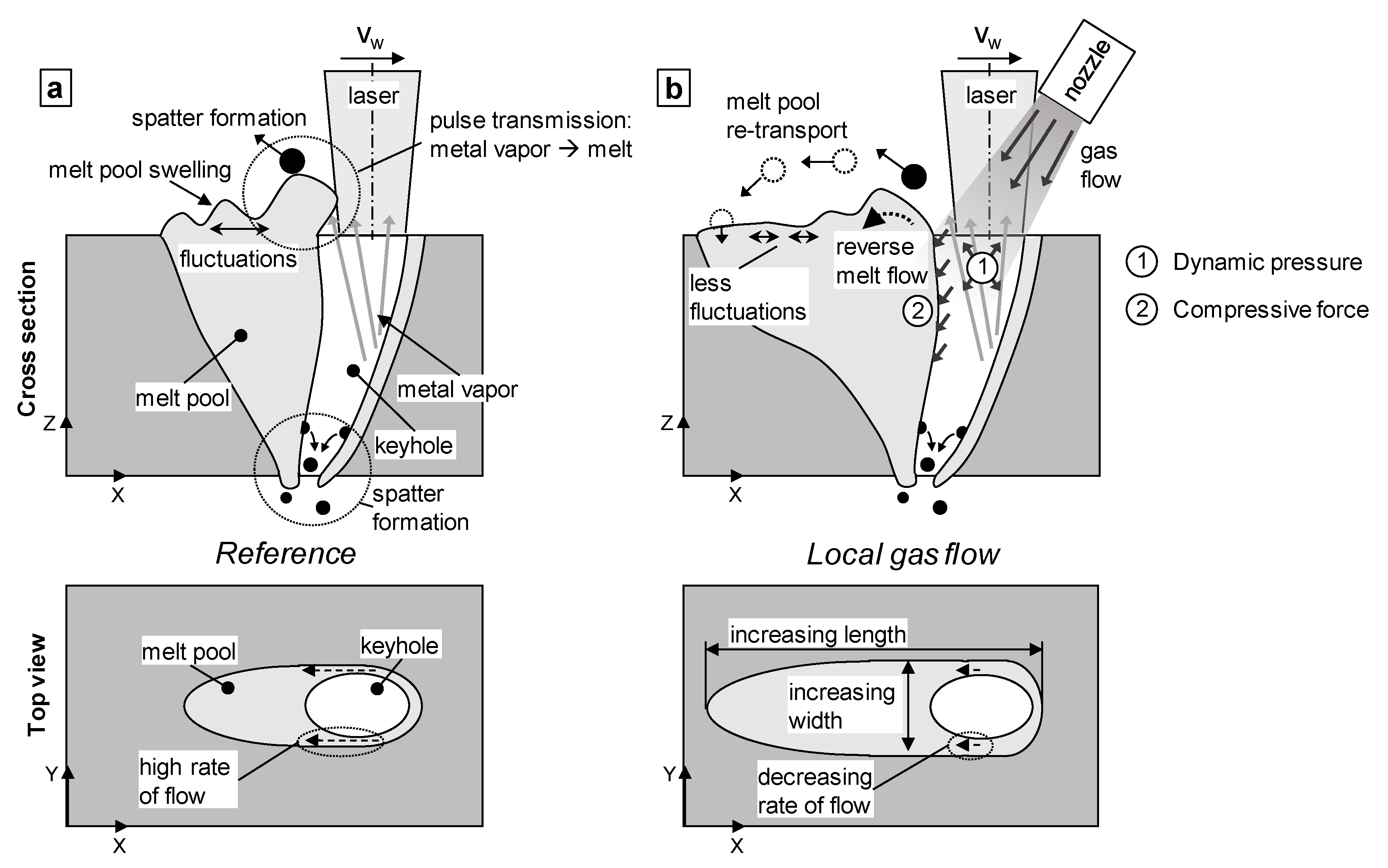
4. Model of Effect Mechanism
The results show a wide range of influencing variables and interaction relationships, which are presented in the following and transferred into a model concept. Based on the reference process for full penetration welding at high welding speeds ≥8 m/min (Figure 11a), the use of the gas flow results in a manipulation of the pressure balance (Equation (3)). Following this, depending on flow rate, a dynamic pressure is exerted which results in a general pressure increase inside the keyhole (Figure 11b). Further, based on the trailing flow orientation, the kinetic energy of the gas causes the formation of a compressive force on the keyhole rear wall. Due to the acting forces, the keyhole rear-sided melt pool swelling shows a much less frequently movement. Instead of a keyhole collapse, a reverse melt flow from the keyhole rear wall into the downstream melt pool is formed. Based on the conditions of a continuous melt flow propagation, the melt pool is extensively elongated. Thereby, this effect can be intensified by the gas flow induced acceleration of melt. Nevertheless, in the case of melt pool movement, spatter are detached in the same way as in the reference process. In contrast, the detached spatter have a significantly lower kinetic energy. This can be attributed to a decreased impulse transfer from the metal vapor to the rear-sided melt, due to a reduced windage of the formed melt pool swelling at the keyhole rear side. Based on the orientation of the gas flow and the escaping metal vapor on the top side of the specimen, the outgassing conditions of the metal vapor flow are affected. Depending on flow rate, the interaction of the contra-orientated flows results in the formation of a heat accumulation due to an impeded degassing. Following, the weld seam top is locally widened. According to the law of continuity (Q = v ∙ ρ ∙ A = const.), this change in flow rate can cause a reduction in flow velocities of the keyhole surrounding melt. Consequently, the melt flow induced dynamic pressure (Equation (4)) is falling. Due to a spatter detachment from the melt pool within the keyhole, the bottom-sided spatter formation mechanism is not affected by a change in pressure balance, as no significant change in keyhole dimensions could be observed at lower flow rates ≤9.6 L/min. [4]
Besides the mentioned model description, there are further physical quantities which can be affected by the local gas supply.
- Pressure/force balance: Based on the interaction of the gas flow and the metal vapor, the gas can be heated up. Thus, the volume of the gas increases, which results in the formation of an expansion pressure. This contributes to another increase in opening force. An additional heating of the gas due to laser adsorption can be classified as insignificant based on the optical properties of argon [32]. Additionally, the force balance of the keyhole can be affected by the kinetic energy of the gas. Due to the trailing flow orientation, the gas flow exerts a compressive force on the keyhole rear wall.
- Melt pool temperature: Besides the discussed effect of heat dissipation due to forced convection and changing outgassing conditions, the melt pool temperature is affected by a change in thermophysical properties. Based on the difference in specific heat capacity, density and thermal conductivity of the gas and the surrounding atmosphere, the heat transfer coefficient is changing. This can result in a manipulation of the Marangoni flow due to changed temperature gradient at the melt pool surface [33].
- Surface tension: Depending on the type of gas used, the surface tension of the melt changes due to adsorption and desorption its chemical components [34,35]. Based on the inert nature of argon, this effect can be classified to be negligible in this investigation [36]. Further, due to the temperature-dependence of the most liquid metals on surface tension [37], the condition of spatter formation (Equation (2)) is affected by the gas flow induced changes in melt pool temperature.
- Vaporization point: Due to the pressure increase inside the keyhole, the boiling point of the material is changing. According to the vapor pressure curve of iron, the normal boiling point is given by a vaporization temperature of approx. 3000 °C [38]. Based on the investigated maximum flow rate of 32 L/min, the internal pressure of the keyhole was increased up to 107 kPa due to the exerted dynamic pressure. According to the investigations of [39], the pressure increase results in a rise in vaporization temperature by up to 160 K. As a result, the rate of evaporation is falling. At a constant laser power, the dissipated energy can cause a decrease in welding depth or seam width. Based on the lower flow rates of the spatter reduced process regime by up to 9.6 L/min, the vaporization temperature is increasing up to 18 K only. Following, this effect can be considered as being of minor significance in this process regime.
In order to quantify the relations of these quantities to the effect mechanism of the local gas flow, further investigations are required to specify their effect in terms of time and importance.
5. Conclusions and Outlook
In this paper, the effect of local gas flows on spatter formation, melt pool dynamics, and associated loss of mass was investigated for the full penetration laser beam welding of stainless austenitic steel AISI 304 (1.4301, X5CrNi18 10) at high welding speeds between 8 m/min and 16 m/min. For this purpose, high-speed video recordings, image processing, high-speed Schlieren imaging, as well as computational analysis data were used. For the investigation, a new type of gas nozzle unit was designed, which was used for supplying argon locally by flow rates from 1.6 L/min up to 32 L/min. Based on the characterization of the reference process without gas supply, the effect of an affected pressure balance due to an exerted dynamic pressure was investigated. By a variation of flow rate and welding speed, different process regimes were determined, which are characterized by different seam qualities, respectively, different welding imperfections (defect-free, humping, melt ejection), as well as by a significant variance in loss of mass. By flow rates up to 9.6 L/min, which corresponds to a dynamic pressure of 9.3 kPa, the loss of mass could be reduced by up to 70% by realizing defect-free welds. A melt pool elongation as well as the formation of a reverse melt flow could be overserved by high-speed videography. This can be attributed to the exerted dynamic pressure as well as to the exerted compressive force inside the keyhole. Further, by using the gas flow, the rear-sided melt pool swelling showed less movement, whereby a collapse of the keyhole could be prevented more often. In the case of a keyhole collapse, spatters were detached following the same mechanisms as in the reference process. However, the detached spatters were characterized by a lower kinetic energy, which is why the spatter were mostly re-transported into the melt pool. Based on high-speed schlieren imaging, it was possible to determine a change in flow pattern while applying the gas flow. Following, the flow orientation at the top and bottom-sided field of view changed against welding direction. A rise in particle speed (2.0–2.5 m/s up to 5 m/s) could be proven by image processing while increasing the flow rate up to 9.6 L/min. By analyzing the dimensions of the keyhole, an increase in keyhole length by up to a factor of 1.9 could be found by flow rates of >8 L/min. Further, a local widening of the weld seam top was determined, which can be attributed to the affected heat balance at the surface area of the melt pool. Despite the spatter reduction, no influence on the frequency of keyhole fluctuation could be found. In contrast, the normalized amplitude of the fluctuation was rising while using the gas flow as well as while increasing the welding speed.
Further investigations will focus on the importance and the relation of the gas flow affected physical quantities of the additional exerted expansion pressure inside the keyhole, as well as the affected spatter formation mechanism due to the temperature dependence of thermophysical properties, respectively, to the changes in surface tension.
Author Contributions
Conceptualization, L.S. and K.S.; methodology, L.S. and K.S.; formal analysis, L.S. and C.J.; investigation, L.S.; resources, L.S.; data curation, L.S.; writing—original draft preparation, L.S.; visualization, L.S.; supervision and discussion, K.S. and J.P.B. All authors have read and agreed to the published version of the manuscript.
Funding
This research received no external funding.
Conflicts of Interest
The authors declare no conflict of interest.
References
- Volpp, J. Dynamik und Stabilität der Dampfkapillare beim Laserstrahltiefschweißen. Ph.D. Thesis, Universität Bremen, Bremen, Germany, 2017. [Google Scholar]
- Zhang, M.; Chen, G.; Zhou, Y.; Li, S. Direct observation of keyhole characteristics in deep penetration laser welding with a 10 kW fiber laser. Opt. Express 2013, 21, 19997–20004. [Google Scholar] [CrossRef]
- Weberpals, J. Nutzen und Grenzen guter Fokussierbarkeit beim Laserschweißen. Ph.D. Thesis, Universität Stuttgart, Stuttgart, Germany, 2010. [Google Scholar]
- Fabbro, R. Melt pool and keyhole behaviour analysis for deep penetration laser welding. J. Phys. D Appl. Phys. 2010, 43, 445501. [Google Scholar] [CrossRef]
- Berger, P.; Schuster, R.; Hügel, H. Zur Bedeutung von gleitenden Stufen an der Kapillarfront beim Schweißen und Schneiden mit Laserstrahlen—Teil 1. Schweißen Schneiden 2011, 63, 20–28. [Google Scholar]
- Volpp, J. Keyhole stability during laser welding—Part II: Process pores and spatters. Prod. Eng. 2017, 11, 9–18. [Google Scholar] [CrossRef]
- Zhang, M.J.; Chen, G.Y.; Zhou, Y.; Li, S.C.; Deng, H. Observation of spatter formation mechanisms in high-power fiber laser welding of thick plate. Appl. Surf. Sci. 2013, 280, 868–875. [Google Scholar] [CrossRef]
- Hügel, H.; Graf, T. Laser in der Fertigung: Grundlagen der Strahlquellen, Systeme, Fertigungsverfahren; Vieweg+Teubner: Wiesbaden, Germany, 2014; Volume 3. [Google Scholar]
- Kaplan, A.; Powell, J. Spatter in laser welding. J. Laser Appl. 2011, 23, 032005. [Google Scholar] [CrossRef]
- Beck, M. Modellierung des Lasertiefschweißens; Teubner: Wiesbaden, Germany, 1996. [Google Scholar]
- Katayama, S.; Tsukamotot, S.; Fabbro, R. Handbook of Laser Welding Technologies; Woodhead Publishing: Sawston, UK, 2013. [Google Scholar]
- Kroos, J.; Gratzke, U.; Simon, G. Towards a self-consistent model of the keyhole in penetration laser beam welding. J. Phys. D Appl. Phys. 1993, 26, 474–480. [Google Scholar] [CrossRef]
- Speker, N.; Haug, P.; Feuchtenbeiner, S.; Hesse, T.; Havrilla, D. BrightLine Weld-Spatter Reduced High Speed Welding with Disk Lasers. In High-Power Laser Materials Processing: Applications, Diagnostics, and Systems VII; International Society for Optics and Photonics: Bellingham, WA, USA, 2018; Volume 10525. [Google Scholar]
- Fetzer, F.; Sommer, M.; Weber, R.; Weberpals, J.-P.; Graf, T. Reduction of pores by means of laser beam oscillation during remote welding of AlMgSi. Opt. Lasers Eng. 2018, 108, 68–77. [Google Scholar] [CrossRef]
- Kallage, P. To application demands adapted beam qualities for improved process results. Int. Congr. Appl. Lasers Electro Opt. 2011, 2011, 605. [Google Scholar] [CrossRef]
- Nagel, F.; Brömme, L.; Bergmann, J.P. Effects of two superimposed laser beams on spatter formation during laser welding of high alloyed steel. J. Laser Appl. 2019, 31, 022005. [Google Scholar] [CrossRef]
- Ning, J.; Zhang, L.-J.; Yin, X.-Q.; Zhang, J.-X.; Na, S.-J. Mechanism study on the effects of power modulation on energy coupling efficiency in infrared laser welding of highly-reflective materials. Mater. Des. 2019, 178, 107871. [Google Scholar] [CrossRef]
- Heider, A. Erweitern der Prozessgrenzen beim Laserstrahlschweißen von Kupfer mit Einschweißtiefen zwischen 1 mm und 10 mm. Ph.D. Thesis, Universität Stuttgart, Stuttgart, Germany, 2018. [Google Scholar]
- Jakobs, S.; Reisgen, U. Laserstrahlschweißen im Vakuum. Stahlbau 2015, 84, 635–642. [Google Scholar] [CrossRef]
- Börner, C.; Dilger, K.; Rominger, V.; Harrer, T.; Krüssel, T.; Löwer, T. Influence of ambient pressure on spattering and weld seam quality in laser beam welding with the solid-state laser. Int. Congr. Appl. Lasers Electro Opt. 2011, 2011, 621–629. [Google Scholar] [CrossRef]
- Clancy, L.J. Aerodynamics; Halstead Press: Ultimo, Australia, 1975. [Google Scholar]
- Kamimuki, K.; Inoue, T.; Yasuda, K.; Muro, M.; Nakabayashi, T.; Matsunawa, A. Prevention of welding defect by side gas flow and its monitoring method in continuous wave Nd:YAG laser welding. J. Laser Appl. 2002, 14, 136–145. [Google Scholar] [CrossRef]
- Fabbro, R.; Slimani, S.; Doudet, I.; Coste, F.; Briand, F. Experimental study of the dynamical coupling between the induced vapour plume and the melt pool for Nd–Yag CW laser welding. J. Phys. D Appl. Phys. 2006, 39, 394–400. [Google Scholar] [CrossRef]
- Herrmann, J. Prozessgase beim Laserschweißen Kostenfaktor oder Garant für wirtschaftliche, stabile und hochwertige Schweißverbindungen. Dvs Ber. 2006, 41, 133–142. [Google Scholar]
- Jovic, G.; Bormann, A.; Proell, J.; Boehm, S. Laser welding of thin stainless steel parts using modified side-gas application for control of spatter and weld shape. Proc. Int. Congr. Laser Adv. Mater. Process. 2019, 1–7. [Google Scholar]
- Zhang, L.; Zhang, J.; Zhang, G.; Bo, W.; Gong, S. An investigation on the effects of side assisting gas flow and metallic vapour jet on the stability of keyhole and molten pool during laser full-penetration welding. J. Phys. D Appl. Phys. 2011, 44, 135201. [Google Scholar] [CrossRef]
- Amara, E.H.; Fabbro, R. Modelling of gas jet effect on the melt pool movements during deep penetration laser welding. J. Phys. D Appl. Phys. 2008, 41, 055503. [Google Scholar] [CrossRef]
- Wu, D.; Hua, X.; Li, F.; Huang, L. Understanding of spatter formation in fiber laser welding of 5083 aluminum alloy. Int. J. Heat Mass Transf. 2017, 113, 730–740. [Google Scholar] [CrossRef]
- Schmidt, L.; Hickethier, S.; Schricker, K.; Bergmann, J.P. Low-spatter high speed welding by use of local shielding gas flows. Proc. SPIE Lase Conf. 2019, 10911. [Google Scholar]
- Schmidt, L.; Schricker, K.; Bergmann, J.P.; Hickethier, S. Effect of gas flow on spatter formation in deep penetration welding at high welding speeds. Proc. Lasers Manuf. Conf. 2019, 1–7. [Google Scholar]
- Settles, G. Schlieren and Shadowgraph Techniques: Visualizing Phenomena in Transparent Media; Springer Science & Business Media: Luxemburg, 2012. [Google Scholar]
- Woods, R.; Spence, B. The Infrared Spectrum of Argon. Phys. Rev. 1934, 4, 669–670. [Google Scholar] [CrossRef]
- Fuhrich, T.; Berger, P.; Hügel, H. Marangoni effect in laser deep penetration welding of steel. J. Laser Appl. 2001, 13, 178–186. [Google Scholar] [CrossRef]
- Keene, B.J. Review of data for the surface tension of pure metals. Int. Mater. Rev. 1993, 38, 157–192. [Google Scholar] [CrossRef]
- Lee, J.; Morita, K. Evaluation of Surface Tension and Adsorption for Liquid Fe-S Alloys. ISIJ Int. 2002, 42, 588–594. [Google Scholar] [CrossRef] [Green Version]
- Kern, M. Gas-und magnetofluiddynamische Maßnahmen zur Beeinflussung der Nahtqualität beim Laserstrahlschweißen. Ph.D. Thesis, Universität Stuttgart, Stuttgart, Germany, 1999. [Google Scholar]
- Morohoshi, K.; Uchikoshi, M.; Isshiki, M.; Fukuyama, H. Surface Tension of Liquid Iron as Functions of Oxygen Activity and Temperature. ISIJ Int. 2011, 51, 1580–1586. [Google Scholar] [CrossRef] [Green Version]
- Zhang, Y.; Evans, J.R.G.; Yang, S. Corrected Values for Boiling Points and Enthalpies of Vaporization of Elements in Handbooks. J. Chem. Eng. Data 2011, 56, 328–337. [Google Scholar] [CrossRef] [Green Version]
- Beutl, M.; Pottlacher, G.; Jäger, H. Thermophysical properties of liquid iron. Int. J. Thermophys. 1994, 15, 1323–1331. [Google Scholar] [CrossRef]
Figure 1.
(a) Schematic experimental setup; (b) Helium flow pattern visualized by schlieren imaging at plane-parallel camera position (0°); (c) Specs of used gas nozzle unit.
Figure 1.
(a) Schematic experimental setup; (b) Helium flow pattern visualized by schlieren imaging at plane-parallel camera position (0°); (c) Specs of used gas nozzle unit.

Figure 2.
Loss of mass and melt pool dynamics of the reference process as function of welding speed.
Figure 2.
Loss of mass and melt pool dynamics of the reference process as function of welding speed.

Figure 3.
Process window of weld seam qualities depending on welding speed and flow rate.

Figure 4.
Loss of mass depending on flow rate and process characteristics for: (a–d) Reference process; (e–h) Gas-assisted process.
Figure 4.
Loss of mass depending on flow rate and process characteristics for: (a–d) Reference process; (e–h) Gas-assisted process.

Figure 5.
Spatter formation mechanism representing in time of: (a) Reference process; (b) Gas-assisted process.
Figure 5.
Spatter formation mechanism representing in time of: (a) Reference process; (b) Gas-assisted process.

Figure 6.
(a) Schematic of used schlieren setup; (b–g) Schlieren records of the reference and gas-assisted process (argon) depending on welding speed.
Figure 6.
(a) Schematic of used schlieren setup; (b–g) Schlieren records of the reference and gas-assisted process (argon) depending on welding speed.

Figure 7.
Top-sided particle speed depending on flow rate for welding speeds of: (a) 8 min; (b) 10 m/min; (c) 12 m/min and (d) 16 m/min.
Figure 7.
Top-sided particle speed depending on flow rate for welding speeds of: (a) 8 min; (b) 10 m/min; (c) 12 m/min and (d) 16 m/min.

Figure 8.
Keyhole dimensions as function of welding speed and flow rate: (a) Keyhole width; (b) Keyhole length.
Figure 8.
Keyhole dimensions as function of welding speed and flow rate: (a) Keyhole width; (b) Keyhole length.

Figure 9.
Comparison of reference process and gas-assisted process at a welding speed of 12 m/min regarding: (a,b) Keyhole length as function of time; (c,d) Frequency spectrum of keyhole oscillation.
Figure 9.
Comparison of reference process and gas-assisted process at a welding speed of 12 m/min regarding: (a,b) Keyhole length as function of time; (c,d) Frequency spectrum of keyhole oscillation.

Figure 10.
Cross sections of weld seam geometries depending on flow rate and welding speed.

Figure 11.
Schematic illustration of the effect mechanism: (a) Reference process; (b) Local gas flow.
Figure 11.
Schematic illustration of the effect mechanism: (a) Reference process; (b) Local gas flow.


Table 1.
Chemical composition of stainless steel 1.4301 in mass % according to DIN EN 10088-3.
| Cr | Ni | C | Si | Mn | Fe |
|---|---|---|---|---|---|
| 17.00–19.00 | 8.00–10.00 | ≤0.07 | ≤1.00 | ≤2.00 | Bal. |
Table 2.
Laser properties and settings.
| Wavelength | Fiber Diameter | Focal Length Collimation | Focal Length Focus | Spot Diameter * | Focal Position | Rayleigh Length * |
|---|---|---|---|---|---|---|
| 1030 nm | 200 µm | 200 mm | 280 mm | 274 µm | 0 mm | 2.38 mm |
* Measured by using FocusMonitor (Primes GmbH, Pfungstadt, Germany).
Table 3.
Defect-free welding parameters at lowest loss of mass.
| Experimental Welding Parameters | ||||
|---|---|---|---|---|
| Welding Speed in m/min | 8 | 10 | 12 | 16 |
| Laser Power in W | 2700 | 3100 | 3700 | 4800 |
| Flow Rate in L/min | 8.0 | 6.4 | 4.8 | 4.8 |
Table 4.
Frequency and normalized amplitude of keyhole fluctuation determined by FFT.
| Process Parameters | 8 m/min * 2.700 W | 10 m/min 3.100 W | 12 m/min 3.700 W | 16 m/min 4.800 W | ||||
|---|---|---|---|---|---|---|---|---|
| Mode | Ref | Gas | Ref | Gas | Ref | Gas | Ref | Gas |
| Flow rate in L/min | / | 8 | / | 6.4 | / | 4.8 | / | 4.8 |
| Frequency in Hz | 720 * | 440 * | 760 | 760 | 720 | 760 | 640 | 760 |
| Normalized amplitude | 0.012 * | 0.016 * | 0.016 | 0.048 | 0.041 | 0.048 | 0.038 | 0.058 |
* High noise in measurement data
© 2020 by the authors. Licensee MDPI, Basel, Switzerland. This article is an open access article distributed under the terms and conditions of the Creative Commons Attribution (CC BY) license (http://creativecommons.org/licenses/by/4.0/).
Share and Cite
MDPI and ACS Style
Schmidt, L.; Schricker, K.; Bergmann, J.P.; Junger, C. Effect of Local Gas Flow in Full Penetration Laser Beam Welding with High Welding Speeds. Appl. Sci. 2020, 10, 1867. https://doi.org/10.3390/app10051867
AMA Style
Schmidt L, Schricker K, Bergmann JP, Junger C. Effect of Local Gas Flow in Full Penetration Laser Beam Welding with High Welding Speeds. Applied Sciences. 2020; 10(5):1867. https://doi.org/10.3390/app10051867
Chicago/Turabian StyleSchmidt, Leander, Klaus Schricker, Jean Pierre Bergmann, and Christina Junger. 2020. "Effect of Local Gas Flow in Full Penetration Laser Beam Welding with High Welding Speeds" Applied Sciences 10, no. 5: 1867. https://doi.org/10.3390/app10051867
Note that from the first issue of 2016, this journal uses article numbers instead of page numbers. See further details here.