Carbon Dioxide Uptake by MOC-Based Materials
by
 , , , and
Ondřej Jankovský
1 ,
,
Michal Lojka
1,
Anna-Marie Lauermannová
1,
Filip Antončík
1,
Milena Pavlíková
2,
Zbyšek Pavlík
2 and
David Sedmidubský
1,* 1
Department of Inorganic Chemistry, Faculty of Chemical Technology, University of Chemistry and Technology, Technická 5, 166 28 Prague 6, Czech Republic
2
Department of Materials Engineering and Chemistry, Faculty of Civil Engineering, Czech Technical University in Prague, Thákurova 7, 166 29 Prague 6, Czech Republic
*
Author to whom correspondence should be addressed.
Appl. Sci. 2020, 10(7), 2254; https://doi.org/10.3390/app10072254
Submission received: 6 March 2020
/
Revised: 20 March 2020
/
Accepted: 24 March 2020
/
Published: 26 March 2020
(This article belongs to the Special Issue Progressive Cement and Glass-Based Composites and Structures)
Abstract
:Featured Application
The highest potential of magnesium oxychloride cement (MOC) is its capability to be used as a component of low-energy building composite materials while acting as a CO2 sink. The results of this contribution also show that MOC can be used as a binder in advanced building materials that have particular properties, and therefore specific application potentials. Formation and hardening of this material are rather fast, so the material can be used in quick repairs as well as a protection layer. This property is also beneficial for use in prefabrication, due to the possibility of unmolding after a shorter time compared to Portland cement (PC) materials, so the whole production process can be considered more effective. Somewhat significant importance should be given to its ability to capture CO2, which not only makes it more eco-friendly, but also improves its mechanical properties.
Abstract
In this work, carbon dioxide uptake by magnesium oxychloride cement (MOC) based materials is described. Both thermodynamically stable magnesium oxychloride phases with stoichiometry 3Mg(OH)2∙MgCl2∙8H2O (Phase 3) and 5Mg(OH)2∙MgCl2∙8H2O (Phase 5) were prepared. X-ray diffraction (XRD) measurements were performed to confirm the purity of the studied phases after 7, 50, 100, 150, 200, and 250 days. Due to carbonation, chlorartinite was formed on the surface of the examined samples. The Rietveld analysis was performed to calculate the phase composition and evaluate the kinetics of carbonation. The SEM micrographs of the sample surfaces were compared with those of the bulk to prove XRD results. Both MOC phases exhibited fast mineral carbonation and high maximum theoretical values of CO2 uptake capacity. The materials based on MOC cement can thus find use in applications where a higher concentration of CO2 in the environment is expected (e.g., in flooring systems and wall panels), where they can partially mitigate the harmful effects of CO2 on indoor air quality and contribute to the sustainability of the construction industry by means of reducing the carbon footprints of alternative building materials and reducing CO2 concentrations in the environment overall.
1. Introduction
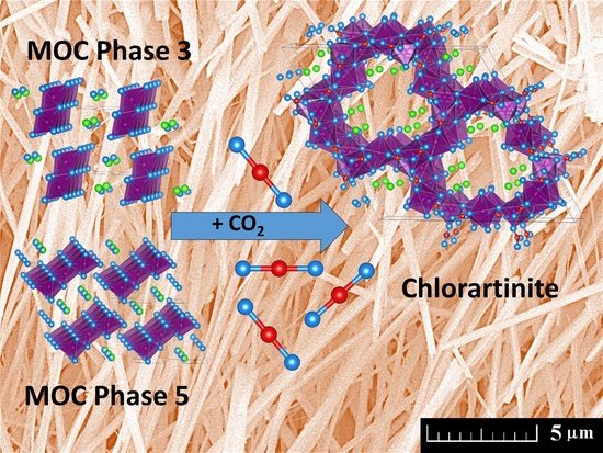
Magnesium oxychloride cement (MOC), also known as Sorel cement, was discovered by French engineer Stanislas Sorel in 1867 [1]. Since then, it has often been compared to Portland cement (PC), which was discovered just a few years earlier. It is formed using a mixture of magnesium oxide with an aqueous solution of magnesium chloride in a certain ratio. The ratios in the system MgO-MgCl2-H2O are significant for each phase of MOC: Phase 2 (2Mg(OH)2∙MgCl2∙4H2O, MOC 2-1-4) and Phase 9 (9Mg(OH)2∙MgCl2∙5H2O, MOC 9-1-5), which are stable at elevated temperatures (~100 °C); and Phase 3 (3Mg(OH)2∙MgCl2∙8H2O, MOC 3-1-8) and Phase 5 (5Mg(OH)2∙MgCl2∙8H2O, MOC 5-1-8), which are stable at ambient temperature until they react with CO2 or H2O. [2,3,4] The crystal structures of Phase 3 and 5 formed by double and triple ribbons of edges shared MgO6 octahedra with water molecules and chloride anions in the interstitial region are shown in Figure 1. The drawings were produced by VESTA Software [5].
MOC phases and MOC-based composites have been intensively studied in recent years. Synthesis, structure, and the thermal stability of magnesium oxychlorides in particular were studied in detail [6,7]. MOC is a non-hydraulic versatile binder with specific properties, which make it superior to PC. One of the most significant properties is its specific density, which is considerably lower and possesses materially high compressive and flexural strength. Other superior properties are its elevated fire resistance, resistance to abrasion, and low thermal conductivity. All of these properties develop in quite a short curing time, so the material is suitable for quick repairs. Further, MOC is not affected by oils, grease, or paint [8,9,10,11], and it is less alkaline (pH~10) than PC, making it appropriate for use with glass fibers and preventing the aging process as well as with other fillers and aggregates such as tire rubber, synthetic resin, and wood particles [12]. The advantage of MOC also lies in the fact that it has a high bonding capacity with different types of filers including secondary raw materials coming from industrial processes.
The versatility and functional performance of MOC-based materials have spurred considerable research into product design, development, and characterization [13,14,15]. Properties of MOC cement-based materials make them applicable in many ways—primarily as a flooring material, but also in fire protective systems, grinding wheels, decoration, wall insulation, and others [16,17].
At the same time, these materials have also some disadvantages, especially when they come into contact with water [18,19]. MOC has a low water resistance due to magnesium chloride leaching, a corrosive compound that causes severe damage when it comes in contact with metals [20,21,22]. The rest of the material is then left in the form of hydrated brucite (Mg(OH)2) as the binding phase. This process can be prevented by improving the stability of MOC in humid conditions, which can be achieved naturally by letting the surface of Sorel cement react with CO2 from the air. The reaction provides magnesium chlorocarbonates to the surface of the original material. Another method of improving MOC is to use a very small amount of additives such as phosphoric acid or soluble phosphates of alkali metals, alkaline earth metals, aluminum, ammonia, or iron. This step causes the formation of insoluble phosphate complexes that enhance the waterproofness of Sorel cement [23,24]. The addition of silica fume or fly ash is also a suitable way of improving MOC-based materials [25].
The main environmental advantage of MOC is its ability to store CO2—one of the main greenhouse gasses (GHGs)—in the form of carbonates. MOC thus acts as a CO2 sink [26]. This process is called carbon mineralization, and due to the increasing amount of GHG in the atmosphere, it has recently been intensively studied [27,28,29,30,31,32].
Carbonation of MOC Phases is beneficial for the environment as well as for MOC itself, making the material harder and tougher as a result of its denser microstructure [33,34,35,36]. The significance of these issues has been documented by monitoring air pollution [37,38,39]. Using carbonation curing of cement-based materials during the preparation of building materials has attracted wide attention [40,41,42,43]. Similarly, CO2 uptake within the carbonation of MOC phases can be beneficially used both from an environmental point of view, and in improving the performances of MOC-based materials.
In this study, the uptake of CO2 by MOC Phases 3 and 5 is examined along with the long-term kinetics of this process. The morphology of both materials was analyzed using scanning electron microscopy, and the chemical composition of the precipitated MOC phases was determined using energy dispersive spectroscopy. The kinetics of the carbonation of formed stable MOC phases has not previously been reported in the literature in regards to the assumed high CO2 uptake capacity by carbonated minerals and its use in the passive control of indoor air quality. This could partially reduce the concentration of CO2 in the polluted environments, and thus slow down global warming-related effects.
2. Materials and Methods
The following chemicals were used for the syntheses: MgCl2∙6H2O (>99%, Penta, Czech Republic), MgO (>8%, Penta, Czech Republic), and deionized water (16.8 MΩ).
The ratio of 5 MgO to MgCl2∙6H2O was used for the synthesis of a stoichiometric phase of MOC with a composition 5Mg(OH)2∙MgCl2∙8H2O (termed as Phase 5, also known as Mg3(OH)5Cl∙4H2O). To prepare the first sample, 30.6 g of MgCl2∙6H2O was dissolved in 19.0 g of deionized water. In the next step, 30.4 g of magnesium oxide was added, and the suspension was intensively stirred for 10 min. Equation (1) summarizes the formation of Phase 5:
Similarly, the stoichiometric Phase 3 (3Mg(OH)2∙MgCl2∙8H2O or Mg2(OH)3Cl∙4H2O) was prepared by mixing MgO, MgCl2∙6H2O and H2O in the molar ratio 3:1:5. To prepare the second sample, 39.1 g of MgCl2∙6H2O was dissolved in 17.3 g of deionized water. In the next step, 23.2 g of magnesium oxide was added, and the suspension was intensively stirred for 5 min. The formation of magnesium oxychloride cement MOC 3-1-8 is summarized in the following Equation (2):
Suspensions were used to prepare small samples in XRD holders (Figure 2). Samples were stored indoor at ambient temperature, with an excess of humidity and carbon dioxide. Figure 2 shows the photography of prepared samples in XRD holders.
For the study of the surface morphology, scanning electron microscopy (SEM) was used (Tescan MAIA 3). Elemental composition and mapping were characterized by energy dispersive spectroscopy (EDS) using X-Max150 analyzer equipped with a 20-mm2 SDD detector (Oxford instruments) and AZtecEnergy software. The sample was put on a carbon conductive tape in order to ensure the conductivity of the experiments. For both SEM and SEM-EDS analyses, the electron beam was set to 10 kV with a 10-mm work distance.
X-ray powder diffraction (XRD) was carried out by a Bruker D2 Phaser, a powder diffractometer with Bragg-Brentano geometry, applying CuKα radiation (λ = 0.15418 nm, U = 30 kV, I = 10 mA) with a rotation of 5 rpm. The step size was set to of 0.02025° (2θ), and the overall data were acquired in the range of 5–80°. Measurements were performed on samples matured for 7, 28, 50, 100, 150, 200, and 250 days. After 250 days, the particular samples were manually homogenized in an agate mortar and measured in a powder form to obtain information on the bulk phase composition. Rietveld analysis was performed for the quantification of the identified phases.
3. Results and Discussion
Two MOC phases were prepared and characterized. The phases under study with the compositions 3Mg(OH)2∙MgCl2∙8H2O and 5Mg(OH)2∙MgCl2∙8H2O are referred to as Phases 3 and 5, respectively. The phase purities of both phases were determined using XRD analysis after 7 days (see Figure 3). A fast formation of Phase 3 was confirmed, and a single-phase composition was obtained (ICDD 00-007-0412). Similar results were also obtained for Phase 5. The formation of Phase 5 (ICDD 00-007-0420) was confirmed with no significant impurities. Figure 3 shows the XRD patterns measured after 7 days for MOC Phases 3 and 5.
Another XRD measurement was performed after 50 days of samples maturing. In both samples, chlorartinite was formed on the surface due to carbonation (see Figure 4). Phase 3 reacted with carbon dioxide forming Mg2(CO3)(OH)Cl∙2H2O (ICDD 00-061-0391), while Phase 5 formed Mg2(CO3)(OH)Cl∙3H2O (ICDD 00-00-0278). A tubular crystal structure of the dihydrate formed by MgO6 octahedra interconnected by carbonate anions with chloride anions and water molecules located inside the channels is depicted in Figure 5. It is apparent from the comparison with the initial structures of Phases 3 and 5 (Figure 1) that the CO2 incorporation into the system required a complete reconstruction of the MgO6 network and, in the case of Phase 5, the formation of another phase (see Equation (4) below). Hence, a relatively slow kinetics of the carbonation process can be anticipated. Figure 4 shows the XRD pattern of MOC Phases 3 and 5 after 50 days of maturing. Figure 5 shows the crystal structure of the chlorartinite phase.
XRD measurements with subsequent Rietveld analysis were performed again after 100, 150, 200, and 250 days of maturing. In both samples, the content of chlorartinite increased with the aging time of the samples. However, as can be seen from Figure 6, the rate of chlorartinite formation was different for Phases 3 and 5. In the case of Phase 3, MOC almost disappeared after 250 days, while chlorartinite represented the dominant phase. The carbonation of Phase 5 was slower than Phase 3, likely due to the phase separation. After 150 days, the surface of the sample contained similar amounts of Phase 5 and chlorartinite. After 250 days, this sample contained 46% of Phase 5 and 54% of chlorartinite. The XRD patterns acquired on 250-day samples are shown in Figure 7 for both surfaces and bulk. It is obvious from Figure 7 that the carbonation took place mainly on the surface. Although the Phase 3 sample contained over 95 wt% chlorartinite, in the whole volume the content of chlorartinite did not exceed 15 wt%. Similar results were obtained for Phase 5, where the content of chlorartinite in the bulk was even lower. Figure 6 shows the surface phase composition of Phases 3 and 5 after 7, 50, 100, 150, 200, and 250 days of sample ageing. Figure 7 shows the phase composition of the surface and bulk (powder) of Phases 3 and 5 assessed for 250-day samples.
SEM micrographs were acquired to study the microstructure of the 250-day MOC samples. The typical needle-like crystalline structure of Phases 3 and 5 were obtained in the bulk at high magnification (see Figure 8). The needles were 1–5 μm long and approximately 0.5 μm wide. On the other hand, the morphology of the surface was different. Due to carbonation (formation of chlorartinite), the surface contained a lower amount of needles in both samples. More needles (MOC phase) were detected in Phase 5 than Phase 3, which is in good agreement with the XRD results. The EDS chemical composition was also measured at three different locations in the sample (surface, center, and bottom). High purity of both samples was confirmed when only magnesium, oxygen, chlorine, and carbon were detected. The EDS data confirmed the highest carbon content on the surface of the tested samples. The carbon content in the center and on the bottom of the analyzed samples was significantly lower. Figure 8 shows the SEM micrographs of the surface and bulk (fracture surface) of the Phases 3 and 5 samples scanned after 250 days of materials ageing. The EDS data measured from the surface, center, and bottom of the samples are also provided.
Both MOC phases analyzed in this study exhibited fast formation of chlorartinite as a result of their reaction with carbon dioxide. The carbon footprint of MOC cement-based materials will be thus significantly and quickly reduced. Based on the great sorption activity of Phase 3 towards CO2, it is estimated that 1 kg of Phase 3 could theoretically incorporate 211 g of CO2, as formulated in Equation (3):
Similarly, assuming carbonation of Phase 5 in accordance with Equation (4),
where maximum calculated theoretical CO2 uptake capacity of Phase 5 was 331 g/kg. However, these are theoretical assumptions only, requiring a high concentration of CO2 in the surrounding air, and full-volume carbonation of MOC phases. On the other hand, increased global CO2 emissions pose a threat to the Earth’s atmospheric environments. It was reported that the annual CO2 concentration at the Earth’s surface in 2017 reached 405 ppm [44], which is approximately quadruple that of the early 1960s [45]. Therefore, any attempt at a reduction of the carbon footprint of construction materials is of particular importance from a sustainability point of view.
The production of Portland cement, as a material that is competitive to MOC cement, represents 5–8% of global CO2 emissions [46,47]. In this sense, alternative approaches to reducing CO2 emissions associated with the manufacture of the binder phase in concrete and other construction materials are in demand [48]. Seo et al. [44] reported on the potential of CO2 reduction materialized by carbonation curing. He calculated the CO2 uptake capacity of Portland cement during an accelerated carbonation test as 12.3%. The computing was done based on the thermogravimetry (TG) and calculation of the difference between the weight loss at 500–720 °C of carbonated and noncarbonated cement paste samples. This was a similar level of CO2 uptake as observed in a study published by Jang and Lee [41]. Nevertheless, this CO2 uptake capacity corresponds with the 5% CO2 concentration within the accelerated carbonation test. The normal level of CO2 concentration in the air is 250–400 ppm [49]. In occupied spaces with good air exchange, the concentration of CO2 varies in the 400–1000 ppm range. This means that the applied CO2 concentration in accelerated carbonation tests was typically even 200 times higher than the normal CO2 concentration in air. The significant reduction of CO2 uptake by Portland cement paste can be therefore be anticipated under standard atmospheric conditions. Moreover, the sequestration of CO2 as a result of the carbonation of Portland cement paste in normal environments is extremely slow [50], contrary to the fast formation of chlorartinite from MOC phases.
Based on the data provided and analysis conducted in this study, it can be concluded that MOC cement represents an alternative construction binder for the production of low carbon materials that can partially mitigate the atmospheric concentration of CO2, which is the main constituent of greenhouse gases related to global warming issues [51].
4. Conclusions
The issue of global warming has resulted in a climate crisis faced by people all over the world. Annually, billions of metric tons of Portland cement are produced around the world, which represents a serious environmental burden due to the release of huge amounts of CO2 within the decomposition of limestone and burning of coal in cement production plants. As Portland cement and cement-based materials are the most widespread materials in the construction industry, there is a need to develop and discover alternative cement materials with similar or better functional properties than Portland cement, with a lower negative environmental impact.
In this work, MOC was studied as an alternative to Portland cement binder. Based on the conducted tests and analyses, the fast formation and hardening of both stable MOC phases was documented, which is an advantageous property and contrary to the significantly slower hardening of Portland cement-based materials. This could be beneficially exploited in repair applications, prefabrication, and the speeding up of construction processes. Specific attention was paid to the ability of MOC to capture CO2 from the environment, making it eco-friendly, but also resulting in a more dense and mechanically resistant structure than was anticipated. Both MOC phases proved their fast mineral carbonation, whereas the maximum theoretical CO2 uptake capacity was high and significantly greater than that of Portland cement paste. Nevertheless, one must consider the surface and bulk carbonation effects, relative humidity values, and CO2 concentration available for carbonation reaction in this respect. MOC-based composites could find use in applications where a higher concentration of CO2 in the environment is expected (e.g., in areas and construction sites exposed to higher traffic density, industrial air pollution, etc.). Here, they can be applied in industrial flooring and wall panels. In this case, the concentration of the prevailing component of greenhouse gases will be safely reduced by CO2 uptake in newly formed carbonated MOC phases which will be more durable and resistant against mechanical loads. Based on the free carbonation capacity of MOC-based products, they could also serve as the passive moderators of indoor air climates with respect to the mitigation of excessive CO2 concentrations (which can cause serious health problems).
Author Contributions
Conceptualization, D.S., O.J., M.P., and Z.P.; methodology, O.J., M.P., Z.P., and D.S.; investigation, M.L., A.-M.L., F.A., O.J., M.P., and Z.P.; data curation, M.P., O.J., D.S., and Z.P., writing—original draft O.J., M.P., D.S., and Z.P.; supervision, O.J. All authors have read and agreed to the published version of the manuscript.
Funding
This research was funded by the CZECH SCIENCE FOUNDATION, grant number 19-00262S—Reactive magnesia cements-based composites with selected admixtures and additives.
Acknowledgments
The technical support provided by Pavel Košata from the Faculty of Civil Engineering, CTU Prague, is greatly acknowledged.
Conflicts of Interest
The authors declare no conflict of interest.
References
- Sorel, S. On a new magnesium cement. CR Acad. Sci. 1867, 65, 102–104. [Google Scholar]
- Dinnebier, R.E.; Freyer, D.; Bette, S.; Oestreich, M. 9Mg(OH)2·MgCl2·4H2O, a high temperature phase of the magnesia binder system. Inorg. Chem. 2010, 49, 9770–9776. [Google Scholar] [CrossRef] [PubMed]
- Dinnebier, R.E.; Oestreich, M.; Bette, S.; Freyer, D. 2Mg(OH)2·MgCl2·2H2O and 2Mg(OH)2·MgCl2·4H2O, two high temperature phases of the magnesia cement system. Z. Anorganische Allgemeine Chemie 2012, 638, 628–633. [Google Scholar] [CrossRef]
- Matkovic, B.; Young, J. Microstructure of magnesium oxychloride cements. Nat. Phys. Sci. 1973, 246, 79–80. [Google Scholar] [CrossRef]
- Momma, K.; Izumi, F. VESTA 3 for three-dimensional visualization of crystal, volumetric and morphology data. J. Appl. Crystallogr. 2011, 44, 1272–1276. [Google Scholar] [CrossRef]
- Jiříčková, A.; Lojka, M.; Lauermannová, A.-M.; Antončík, F.; Sedmidubský, D.; Pavlíková, M.; Záleská, M.; Pavlík, Z.; Jankovský, O. Synthesis, structure, and thermal stability of magnesium oxychloride 5Mg (OH)2∙MgCl2∙8H2O. Appl. Sci. 2020, 10, 1683. [Google Scholar] [CrossRef] [Green Version]
- Lojka, M.; Jankovský, O.; Jiříčková, A.; Lauermannová, A.-M.; Antončík, F.; Sedmidubský, D.; Pavlík, Z. Thermal Stability and Kinetics of Formation of Magnesium Oxychloride Phase 3Mg (OH) 2∙MgCl2∙8H2O. Materials 2020, 13, 767. [Google Scholar] [CrossRef] [Green Version]
- Demediuk, T.; Cole, W.; Hueber, H. Studies on magnesium and calcium oxychlorides. Aust. J. Chem. 1955, 8, 215–233. [Google Scholar] [CrossRef]
- Li, Z.; Chau, C. Influence of molar ratios on properties of magnesium oxychloride cement. Cem. Concr. Res. 2007, 37, 866–870. [Google Scholar] [CrossRef]
- Montle, J.; Mayhan, K. The role of magnesium oxychloride as a fire-resistive material. Fire Technol. 1974, 10, 201–210. [Google Scholar] [CrossRef]
- Qiao, H.X.; Zhu, B.R.; Shi, Y.Y.; Dong, J.M.; Elizabeth Wanjiru, M. Strength development and micro-mechanism of magnesium oxychloride cement concrete. Mater. Res. Innov. 2015, 19, S1–S185. [Google Scholar] [CrossRef]
- Zhou, X.; Li, Z. Light-weight wood–magnesium oxychloride cement composite building products made by extrusion. Constr. Build. Mater. 2012, 27, 382–389. [Google Scholar] [CrossRef] [Green Version]
- El-Gammal, M.; El-Alfy, A.; Mohamed, N. Using magnesium oxide wallboard as an alternative building façade cladding material in modern cairo buildings. J. Appl. Sci. Res. 2012, 8, 2024–2032. [Google Scholar]
- Chau, C.K.; Chan, J.; Li, Z. Influences of fly ash on magnesium oxychloride mortar. Cem. Concr. Compos. 2009, 31, 250–254. [Google Scholar] [CrossRef]
- Ozturk, A.; Said, M.; Timuçin, M. Production and characterization of magnesium oxychloride cement bricks for fine polishing of porcelain stoneware tiles. Ind. Ceram. 2011, 31, 89–98. [Google Scholar]
- Karimi, Y.; Monshi, A. Effect of magnesium chloride concentrations on the properties of magnesium oxychloride cement for nano SiC composite purposes. Ceram. Int. 2011, 37, 2405–2410. [Google Scholar] [CrossRef]
- Yunsong, J. Study of the new type of light magnesium cement foamed material. Mater. Lett. 2001, 50, 28–31. [Google Scholar] [CrossRef]
- Záleská, M.; Pavlíková, M.; Jankovský, O.; Lojka, M.; Antončík, F.; Pivák, A.; Pavlík, Z. Influence of waste plastic aggregate and water-repellent additive on the properties of lightweight magnesium oxychloride cement composite. Appl. Sci. 2019, 9. [Google Scholar] [CrossRef] [Green Version]
- Záleská, M.; Pavlíková, M.; Jankovský, O.; Lojka, M.; Pivák, A.; Pavlík, Z. Experimental analysis of MOC composite with a waste-expanded polypropylene-based aggregate. Materials 2018, 11, 931. [Google Scholar] [CrossRef] [Green Version]
- Deng, D. The mechanism for soluble phosphates to improve the water resistance of magnesium oxychloride cement. Cem. Concr. Res. 2003, 33, 1311–1317. [Google Scholar] [CrossRef]
- He, P.; Poon, C.S.; Tsang, D.C.W. Effect of pulverized fuel ash and CO2 curing on the water resistance of magnesium oxychloride cement (MOC). Cem. Concr. Res. 2017, 97, 115–122. [Google Scholar] [CrossRef]
- Tang, S.; Hu, Y.; Ren, W.; Yu, P.; Huang, Q.; Qi, X.; Li, Y.; Chen, E. Modeling on the hydration and leaching of eco-friendly magnesium oxychloride cement paste at the micro-scale. Constr. Build. Mater. 2019, 204, 684–690. [Google Scholar] [CrossRef]
- Cannesson, E.; Manier, S.; Nicholson, J.W. The influence of Group I metal chlorides on water loss and chloride release from magnesium oxychloride cements. Ceram.-Silikáty 2011, 55, 183–187. [Google Scholar]
- Xu, K.; Xi, J.; Guo, Y.; Dong, S. Effects of a new modifier on the water-resistance of magnesite cement tiles. Solid State Sci. 2012, 14, 10–14. [Google Scholar] [CrossRef]
- Li, C.; Yu, H. Influence of fly ash and silica fume on water-resistant property of magnesium oxychloride cement. J. Wuhan Univ. Technol.-Mater. Sci. Ed. 2010, 25, 721–724. [Google Scholar] [CrossRef]
- Pade, C.; Guimaraes, M. The CO2 uptake of concrete in a 100 year perspective. Cem. Concr. Res. 2007, 37, 1348–1356. [Google Scholar] [CrossRef]
- Fernández-Carrasco, L.; Torréns-Martín, D.; Martínez-Ramírez, S. Carbonation of ternary building cementing materials. Cem. Concr. Compos. 2012, 34, 1180–1186. [Google Scholar] [CrossRef]
- Lee, S.-W.; Lee, T.-H.; Park, J.-W.; Park, C.-H.; Kim, H.-J.; Kim, S.-M.; Lee, S.-H.; Song, J.-Y.; Lee, J.-H. The effect of laser irradiation on peel strength of temporary adhesives for wafer bonding. Int. J. Adhes. Adhes. 2015, 57, 9–12. [Google Scholar] [CrossRef]
- Power, I.M.; Dipple, G.M.; Francis, P.S. Assessing the carbon sequestration potential of magnesium oxychloride cement building materials. Cem. Concr. Compos. 2017, 78, 97–107. [Google Scholar] [CrossRef]
- Unluer, C.; Al-Tabbaa, A. Impact of hydrated magnesium carbonate additives on the carbonation of reactive MgO cements. Cem. Concr. Res. 2013, 54, 87–97. [Google Scholar] [CrossRef]
- Unluer, C.; Al-Tabbaa, A. The role of brucite, ground granulated blastfurnace slag, and magnesium silicates in the carbonation and performance of MgO cements. Constr. Build. Mater. 2015, 94, 629–643. [Google Scholar] [CrossRef] [Green Version]
- Xi, F.; Davis, S.J.; Ciais, P.; Crawford-Brown, D.; Guan, D.; Pade, C.; Shi, T.; Syddall, M.; Lv, J.; Ji, L.; et al. Substantial global carbon uptake by cement carbonation. Nat. Geosci. 2016, 9, 880–883. [Google Scholar] [CrossRef] [Green Version]
- Mo, L.; Panesar, D.K. Accelerated carbonation—A potential approach to sequester CO2 in cement paste containing slag and reactive MgO. Cem. Concr. Compos. 2013, 43, 69–77. [Google Scholar] [CrossRef]
- Pu, L.; Unluer, C. Investigation of carbonation depth and its influence on the performance and microstructure of MgO cement and PC mixes. Constr. Build. Mater. 2016, 120, 349–363. [Google Scholar] [CrossRef]
- Vandeperre, L.J.; Al-Tabbaa, A. Accelerated carbonation of reactive MgO cements. Adv. Cem. Res. 2007, 19, 67–79. [Google Scholar] [CrossRef]
- Cannistraro, G.; Cannistraro, M.; Piccolo, A.; Restivo, R. Potentials and limits of oxidative photocatalysisand possible applications in the field of cultural heritage. In Advanced Materials Research; Trans Tech Publications Ltd.: Stafa-Zurich, Switzerland, 2013; pp. 111–117. [Google Scholar]
- Cannistraro, G.; Cannistraro, M.; Cannistraro, A.; Galvagno, A.; Engineer, F. Analysis of air pollution in the urban center of four cities Sicilian. Int. J. Heat Technol. 2016, 34, S219–S225. [Google Scholar] [CrossRef]
- Cannistraro, G.; Cannistraro, M.; Cao, J.; Ponterio, L. New technique monitoring and transmission environmental data with mobile systems. Instrum. Mes. Metrol. 2018, 17, 549. [Google Scholar] [CrossRef]
- Cannistraro, M.; Ponterio, L.; Cao, J. Experimental study of air pollution in the urban centre of the city of Messina. Model. Meas. Control C 2018, 79, 133–139. [Google Scholar] [CrossRef] [Green Version]
- Fang, Y.; Chang, J. Rapid hardening β-C2S mineral and microstructure changes activated by accelerated carbonation curing. J. Therm. Anal. Calorim. 2017, 129, 681–689. [Google Scholar] [CrossRef]
- Jang, J.G.; Lee, H.K. Microstructural densification and CO2 uptake promoted by the carbonation curing of belite-rich Portland cement. Cem. Concr. Res. 2016, 82, 50–57. [Google Scholar] [CrossRef]
- Mo, L.; Zhang, F.; Deng, M. Mechanical performance and microstructure of the calcium carbonate binders produced by carbonating steel slag paste under CO2 curing. Cem. Concr. Res. 2016, 88, 217–226. [Google Scholar] [CrossRef]
- Zhan, B.J.; Xuan, D.X.; Poon, C.S.; Shi, C.J. Mechanism for rapid hardening of cement pastes under coupled CO2-water curing regime. Cem. Concr. Compos. 2019, 97, 78–88. [Google Scholar] [CrossRef]
- Seo, J.H.; Amr, I.T.; Park, S.M.; Bamagain, R.A.; Fadhel, B.A.; Kim, G.M.; Hunaidy, A.S.; Lee, H.K. CO₂ uptake of carbonation-cured cement blended with ground volcanic Ash. Materials 2018, 11, 2187. [Google Scholar] [CrossRef] [PubMed] [Green Version]
- Blunden, J.; Amdt, D.S.; Hartfield, G.; Sánchez-Lugo, A.; Scambos, T.A.; Schreck, C.J.I.; Stammerjohn, S.; Stanitski, D.M.; Willett, K.M.; Bissolli, P. State of Climate in 2017. Bull. Am. Meteorol. Soc. 2018, 99, S1–S310. [Google Scholar]
- Imbabi, M.S.; Carrigan, C.; McKenna, S. Trends and developments in green cement and concrete technology. Int. J. Sustain. Built Environ. 2012, 1, 194–216. [Google Scholar] [CrossRef] [Green Version]
- Kemp, R.; Barteková, E.; Türkeli, S. The innovation trajectory of eco-cement in the Netherlands: A co-evolution analysis. Int. Econ. Econ. Policy 2017, 14, 409–429. [Google Scholar] [CrossRef] [Green Version]
- Gartner, E.; Hirao, H. A review of alternative approaches to the reduction of CO2 emissions associated with the manufacture of the binder phase in concrete. Cem. Concr. Res. 2015, 78, 126–142. [Google Scholar] [CrossRef] [Green Version]
- Wisconsin Department of Health Services; Carbon Dioxide. Available online: https://www.dhs.wisconsin.gov/chemical/carbondioxide.htm (accessed on 17 February 2020).
- Thiery, M.; Villain, G.; Dangla, P.; Platret, G. Investigation of the carbonation front shape on cementitious materials: Effects of the chemical kinetics. Cem. Concr. Res. 2007, 37, 1047–1058. [Google Scholar] [CrossRef]
- Wang, J.; Xu, H.; Xu, D.; Du, P.; Zhou, Z.; Yuan, L.; Cheng, X. Accelerated carbonation of hardened cement pastes: Influence of porosity. Constr. Build. Mater. 2019, 225, 159–169. [Google Scholar] [CrossRef]
Figure 1.
Crystal structures of Phase 3 (left) and Phase 5 (right). Mg atoms are located in the centers of distorted octahedra formed by oxygen atoms. Cl atoms—green; O atoms—blue. Green-blue spheres in the Phase 5 structures correspond to a mixed site occupied by chloride anions and water molecules (hydrogen atoms are not shown).

Figure 2.
Photography of prepared samples in XRD holders: Phase 3 (left) and Phase 5 (right).
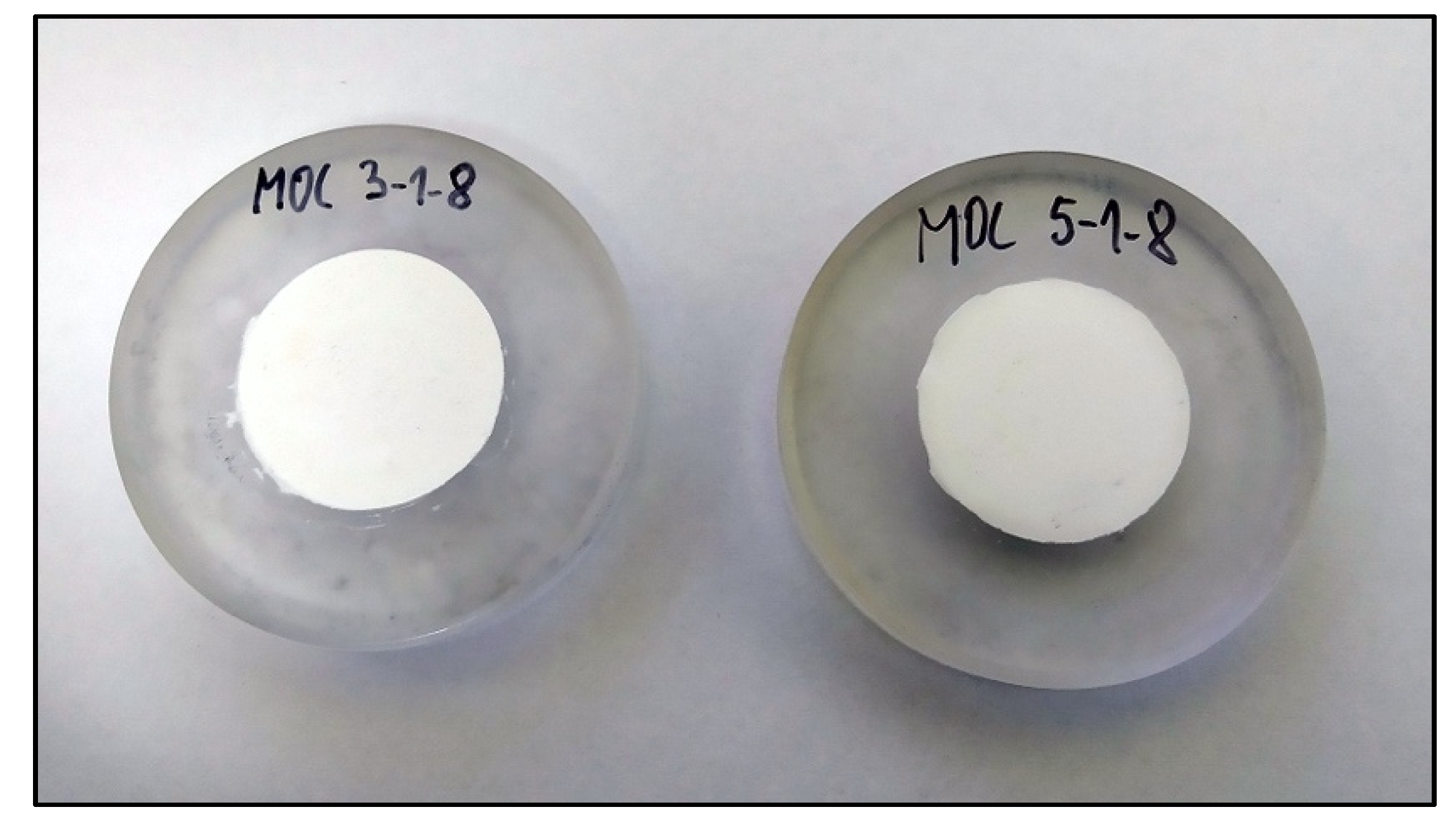
Figure 3.
XRD patterns for magnesium oxychloride cement (MOC) Phases 3 and 5 after 7 days.

Figure 4.
XRD patterns of MOC Phases 3 and 5 after 50 days.

Figure 5.
Crystal structure of the chlorartinite phase. Color scheme is the same as in Figure 1; carbon atoms located in the centers of triangular carbonate molecules are in red.
Figure 5.
Crystal structure of the chlorartinite phase. Color scheme is the same as in Figure 1; carbon atoms located in the centers of triangular carbonate molecules are in red.

Figure 6.
Phase composition of the surface of Phases 3 and 5 after 7, 50, 100, 150, 200, and 250 days of samples ageing.
Figure 6.
Phase composition of the surface of Phases 3 and 5 after 7, 50, 100, 150, 200, and 250 days of samples ageing.

Figure 7.
Phase composition of the surface and bulk (powder) of Phases 3 and 5 at 250 days of sample ageing.
Figure 7.
Phase composition of the surface and bulk (powder) of Phases 3 and 5 at 250 days of sample ageing.
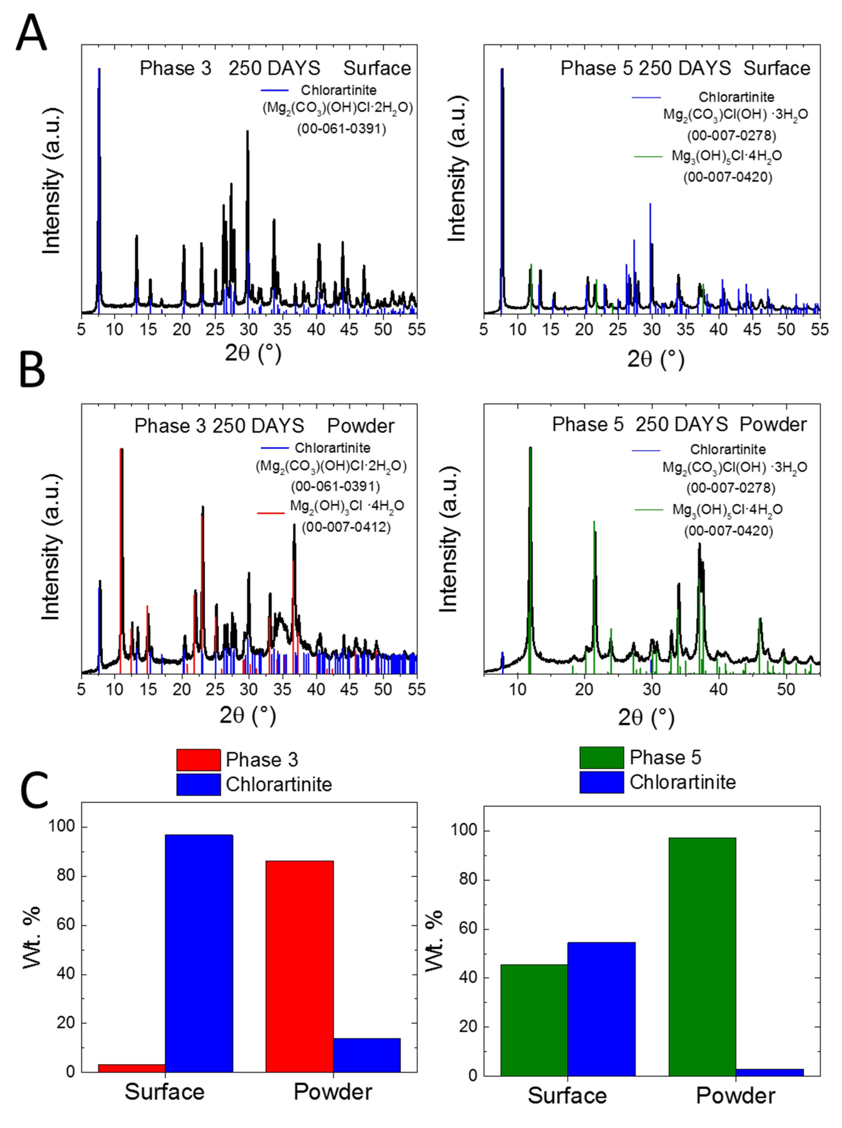
Figure 8.
SEM micrographs of the surface and bulk (fracture surface) of samples of Phases 3 and 5 scanned after 250 days of ageing. The EDS measurements were performed from the surface, center, and bottom of the samples.
Figure 8.
SEM micrographs of the surface and bulk (fracture surface) of samples of Phases 3 and 5 scanned after 250 days of ageing. The EDS measurements were performed from the surface, center, and bottom of the samples.

© 2020 by the authors. Licensee MDPI, Basel, Switzerland. This article is an open access article distributed under the terms and conditions of the Creative Commons Attribution (CC BY) license (http://creativecommons.org/licenses/by/4.0/).
Share and Cite
MDPI and ACS Style
Jankovský, O.; Lojka, M.; Lauermannová, A.-M.; Antončík, F.; Pavlíková, M.; Pavlík, Z.; Sedmidubský, D. Carbon Dioxide Uptake by MOC-Based Materials. Appl. Sci. 2020, 10, 2254. https://doi.org/10.3390/app10072254
AMA Style
Jankovský O, Lojka M, Lauermannová A-M, Antončík F, Pavlíková M, Pavlík Z, Sedmidubský D. Carbon Dioxide Uptake by MOC-Based Materials. Applied Sciences. 2020; 10(7):2254. https://doi.org/10.3390/app10072254
Chicago/Turabian StyleJankovský, Ondřej, Michal Lojka, Anna-Marie Lauermannová, Filip Antončík, Milena Pavlíková, Zbyšek Pavlík, and David Sedmidubský. 2020. "Carbon Dioxide Uptake by MOC-Based Materials" Applied Sciences 10, no. 7: 2254. https://doi.org/10.3390/app10072254
Note that from the first issue of 2016, this journal uses article numbers instead of page numbers. See further details here.