Optimal Design and Control of MMC STATCOM for Improving Power Quality Indicators
by
 , ,
, ,
Ahmed A. Zaki Diab
2,3,* ,
,
Terad Ebraheem
4,
Raseel Aljendy
5,*,
Hamdy M. Sultan
2,5 and
Ziad M. Ali
1,6
1
College of Engineering at Wadi Addawaser, Prince Sattam bin Abdulaziz University, Wadi Aldawaser 11991, Saudi Arabia
2
Electrical Engineering Department, Faculty of Engineering, Minia University, Minia 61111, Egypt
3
Department of Electrical Engineering, Kyushu University, Fukuoka 819-0395, Japan
4
Electrical Engineering Department, Faculty of Engineering, Tishreen University, Latakia 2237, Syria
5
Electrical power systems Department, Moscow Power Engineering Institute “MPEI”, Moscow 111250, Russia
6
Electrical Engineering Department, Aswan Faculty of Engineering, Aswan University, Aswan 81542, Egypt
*
Authors to whom correspondence should be addressed.
Appl. Sci. 2020, 10(7), 2490; https://doi.org/10.3390/app10072490
Submission received: 9 March 2020
/
Revised: 28 March 2020
/
Accepted: 30 March 2020
/
Published: 4 April 2020
(This article belongs to the Special Issue Advances and Technologies in High Voltage Power Systems Operation, Control, Protection and Security)
Abstract
:In recent years, modular multilevel converters (MMC) are becoming popular in the distribution and transmission of electrical systems. The multilevel converter suffers from circulating current within the converter that increases the conduction loss of switches and increases the thermal stress on the capacitors and switches’ IGBTs. One of the main solutions to control the circulating current is to keep the capacitor voltage balanced in the MMC. In this paper, a new hybrid control algorithm for the cascaded modular multilevel converter is presented. The Harris hawk’s optimization (HHO) and Atom search optimization (ASO) are used to optimally design the controller of the hybrid MMC. The proposed structure of modular multilevel inverters allows effective operation, a low level of harmonic distortion in the absence of output voltage filters, a low switching frequency, and excellent flexibility to achieve the requirements of any voltage level. The effectiveness of the proposed controller and the multilevel converter has been verified through testing with the application of the MMC-static synchronous compensator (STATCOM). The stability of the voltage capacitors was monitored with balanced and unbalanced loads on the studied network.
1. Introduction
Recently, with the increased popularity and application of power electronic devices in modern industries, some large electrical loads such as from an AC traction system (single-phase), electric furnaces and modern technologies based on high-tech microprocessors in renewable energy applications cause increasing power quality (PQ) problems [1,2]. Power quality problems appear in electric utility as increased harmonic distortions, phase imbalances and low power factors. Electric devices based on power electronics present themselves as non-linear loads, which are characterized as sources of harmonics in the power system. The harmonic currents cause an increase in the RMS value of the current and let the neutral current make circulations in the electric distribution system. The capacity of the distribution system and power losses are affected by the presence of harmonics [2,3].
The effects of nonlinear unbalanced loads on the performance of the power system is an important issue for the power system operators and attracts the interest of many researchers. Many research papers have proposed different techniques and optimization algorithms to improve power quality indicators in the presence of nonlinear and/or unbalanced loads [4]. The static synchronous compensator (STATCOM) is one of the FACTS devices that introduces an efficient and flexible solution for power quality improvement and disturbance mitigation [5,6,7]. The practical circuit of the STATCOM usually includes two-level voltage source converters (VSC), and a line-frequency transformer is adopted for the enhancement of its voltage and current ratings; however, it results in the heavy, unreliable and expensive design of the compensator [5,6].
The multilevel converters-based STATCOM has received considerable attention from researchers due to its higher capacity that makes it reliable for application in medium- or high-voltage high grids in the absence of line-frequency transformers. Since 1975, the concept of the multilevel converter has been introduced [8]. The multilevel term began with the third-level topology [8,9]. Subsequently, many multilevel converter topologies were developed [10,11,12,13,14,15,16,17,18,19]. However, the basic concept of the multilevel converter is the use of a series of semiconductor power switches with several low DC voltage sources to conduct energy conversion and obtain higher energy. The topology of the multilevel converters has succeeded in addressing some of the main problems in the traditional converters [10,11,12,13,14,15,16,17,18,19]. The most important of these problems are the problems of power quality, especially the voltage and current harmonics [20,21,22,23]. As the number of converter levels increases, the output voltage signal will be as good and as close as possible to the desired waveform [9,10,11,12,13,14,15,16,17,18,19]. But of course, advanced control techniques are needed to improve the performance of multilevel converters and optimize the workflow.
Three major multilevel converters have been applied in high- and medium-power applications, such as the neutral-point clamped multilevel converter (NPCMC), the flying capacitor multilevel converter (FCMC) and the cascaded H-bridge multilevel converter (CHBMC) [8,9]. The major disadvantage of the NPCMC is the inherent voltage imbalance problems, which require an extra auxiliary compensation circuit [8,9]. As for FCMC, besides the need for highly expensive flying capacitors, mainly at low carrier frequencies, this type of multilevel converter is not suitable for those applications with 90° leading or lagging currents. Moreover, for both topologies, as the voltage level has to be increased in high power applications, an increase in the size of the capacitors or in the climbing diodes is required, which makes the control circuit and converter structure more complex. Compared with the previously explained two former topologies, CHBMC requires fewer components in the circuit design, which makes it convenient for physical layout and packaging. The major disadvantage of CHBMC is that it cannot perform properly under imbalanced conditions without feeding from isolated DC sources supplied from multi-winding transforms, which gives rise to the same problems associated with the use of the line-frequency transformer [8,9].
To overcome the previously mentioned problems, a new modular multilevel converter-based STATCOM (MMC STATCOM) is recommended for medium and high voltage applications. The MMC STATCOM is characterized by its availability, compact and modular construction, generation of least harmonics, etc. Moreover, the MMC STATCOM is able to exchange both active and reactive power via the common DC-bus. Accordingly, the active power, which is redistributed in the internal circuits, is utilized for the purpose of negative sequence balance. Consequently, the MMC STATCOM can operate under three-phase imbalance without any intermission.
In this paper, an optimization problem is introduced for the optimal design of the multilevel converter and for determining the optimal parameters of the DC voltage controller. The minimization of total harmonic distortion (THD) in the power system under consideration is introduced as the objective function while keeping the ripple voltage within the allowable ranges and obtaining minimum circulating current. Novel optimization algorithms, namely Atom Search Optimization (ASO) and Harris Hawk optimization (HHO) that have not been reported in the literature for tackling the aforementioned problem of optimization of the values of the capacitors of the MMC STATCOM have been applied. Moreover, to ensure the effectiveness of the proposed optimization techniques, the results obtained from the application of these methods have been tested under two different case studies, nonlinear load and three-phase imbalance.
The paper is organized as follows: in Section 2, a brief review of MMC topologies is introduced in detail; Section 3 introduces the Model of the Modular Multilevel Converter (MMC); the Modular Multilevel Converter-based STATCOM (MMC STATCOM) is introduced in Section 4; Section 5 presents the problem formulation; Section 6 presents the Harris hawk’s optimization (HHO) and atom algorithm in detail; the result simulation presents in Section 7; and the conclusion is stated in Section 8.
2. A Brief Review of MMC Topologies
There are many topologies of the MMC. A comprehensive comparison among these topologies is presented in Table 1 [24,25].
For more explanation to state the motivation of this paper, the level of harmonics in the output voltages and currents of the MMC is very essential and has to be within the allowable limits. The harmonic content could be decreased without the need for any filters with the help of modern control methods [26,27]. In order to obtain the output voltage with an acceptable level of THD in the AC side cascaded configuration, the switching frequency of the two-level converter (main converter) is adjusted to 400 Hz, while the frequency of carriers is taken as 2 kHz. Due to the possible mismatch of synchronization between the main converter and the active filter (H-bridge cascaded model), the fifth and seventh harmonic components may arise, which must be canceled using a number of filters.
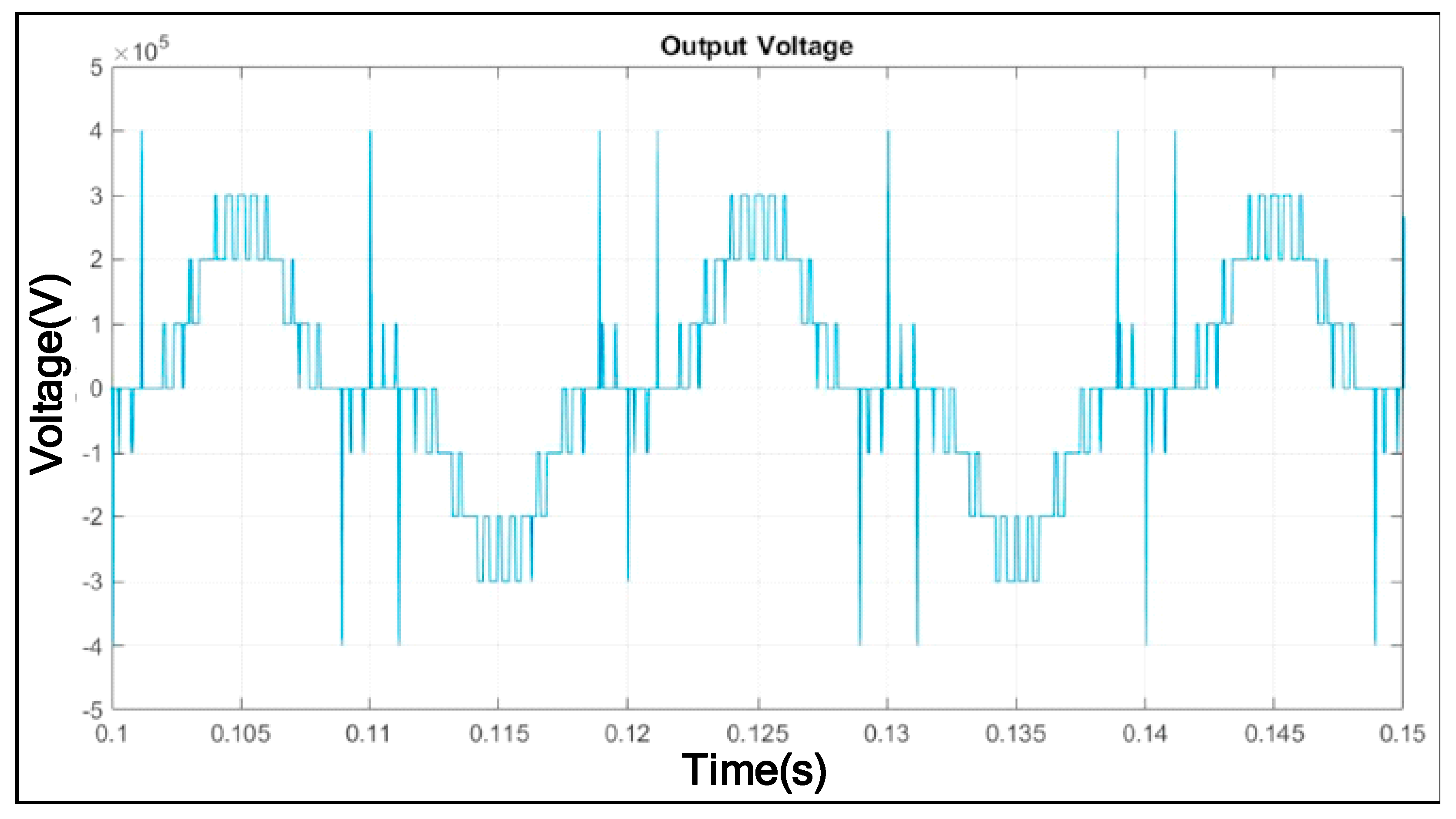
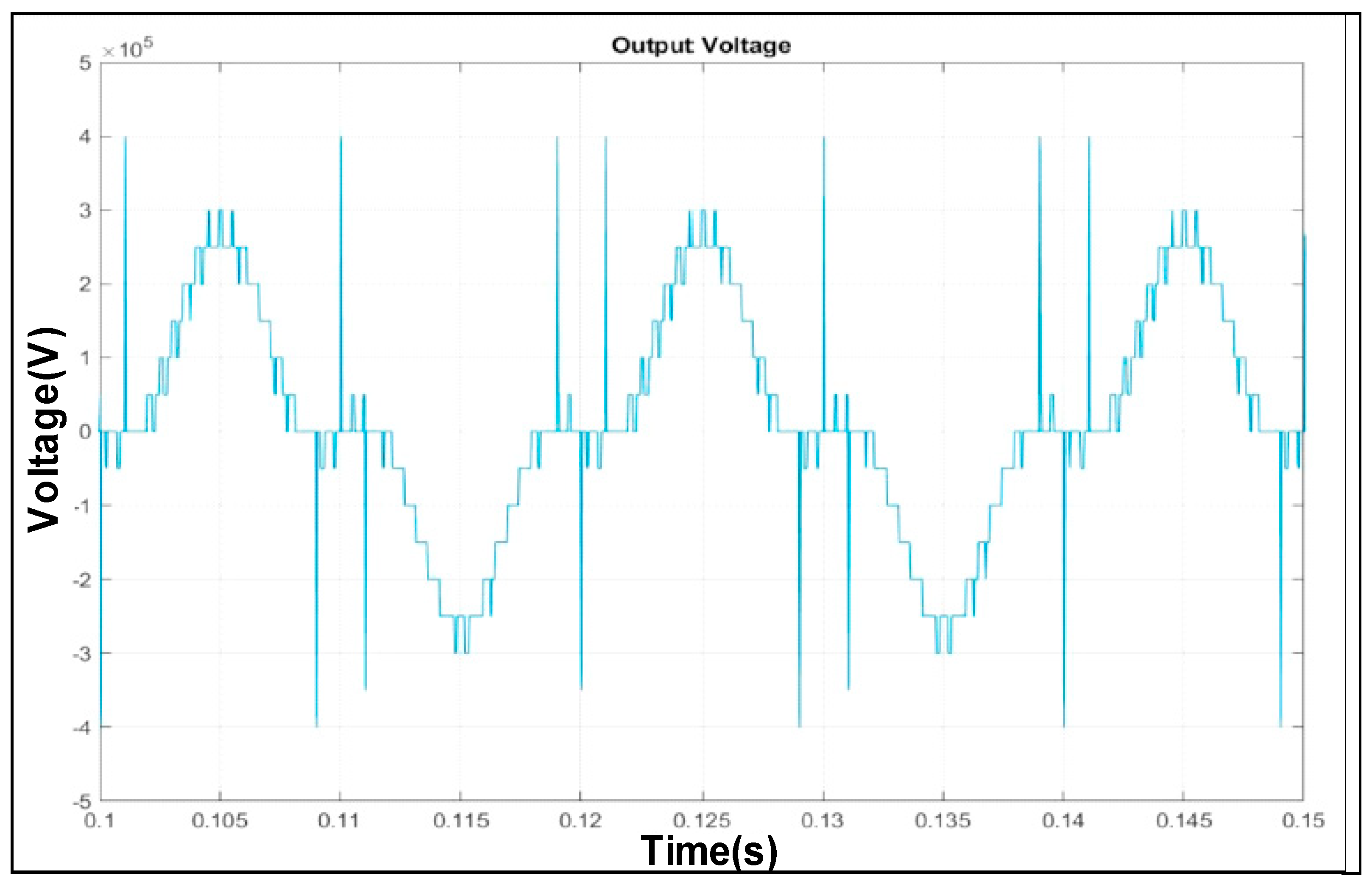
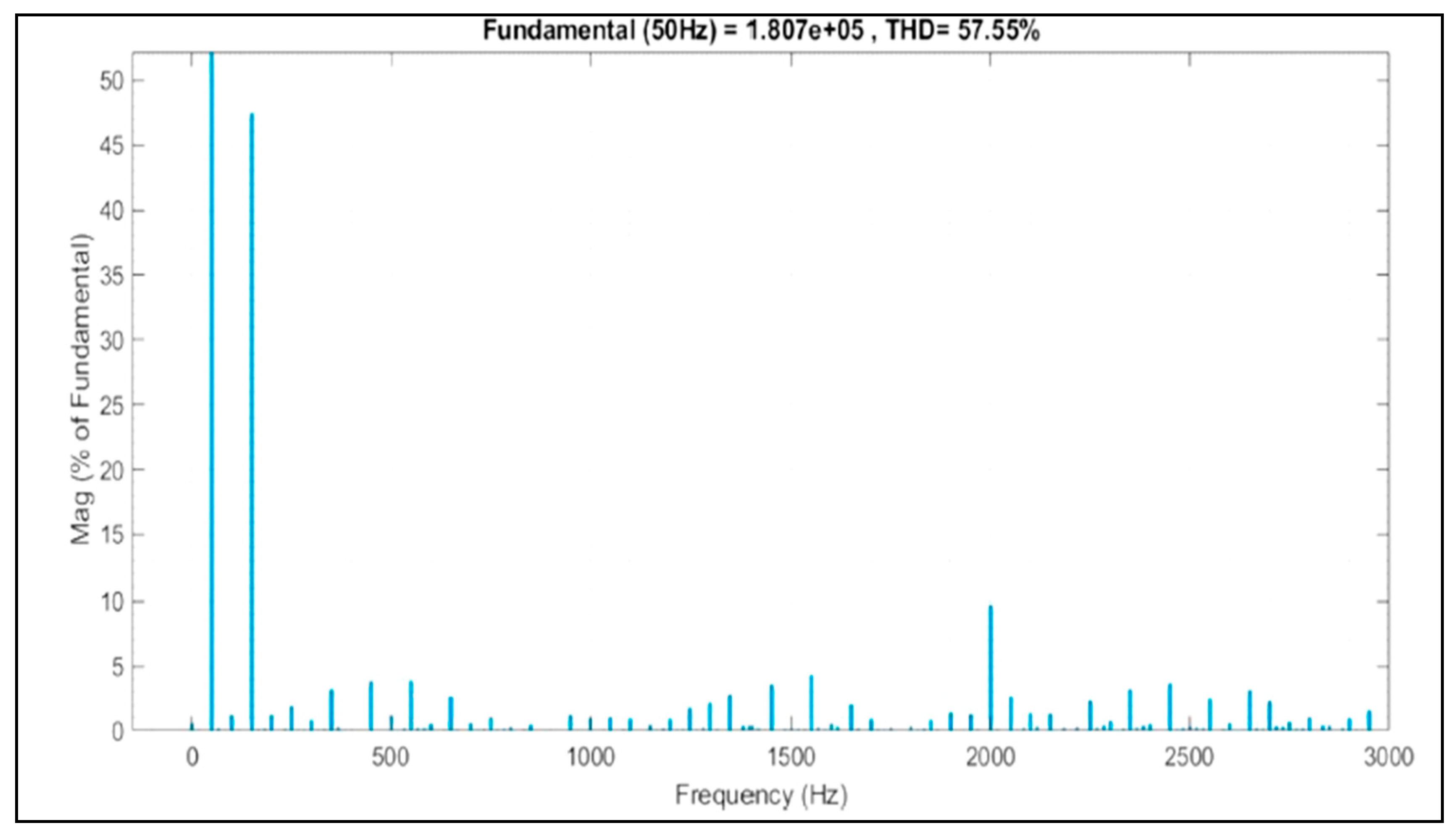
As example, reference [26] presented a comparison between the output voltage and the harmonic spectra generated from the single-phase AC cascaded configuration with two H-bridges on the AC side, which are presented in Figure 1 and Figure 2, and the output voltage and the harmonic spectra generated from the single-phase AC cascaded configuration with 4H-bridges on the AC side, which are presented in Figure 3 and Figure 4. It can be seen from Figure 2 that the third harmonic component has a large value and also that the value of THD is extremely high. That is because the method of third harmonic subtraction allows the multilevel converters to work independently of the load power factor and without the problems of capacitor voltage balancing [26]. The data presented in Figure 4 prove the superiority of the last configuration of 4H-bridges, as the profile of the output voltage harmonic is slightly better, but with an increase in the number of the power electronic devices and the cost of the system. Moreover, reference [26] concludes that the increasing of the series sub-modules (SMs) in the case of using two H-bridges or 4H-bridges will lead to a reduction in the harmonics and over-shoot in the output voltages of the MMC.
The introduced discussion leads the authors to present an optimal design of the control system and the optimal capacitor value of the MMC for the STATCOM application, using the half-bridge SMs to decrease the number of devices and the cost of implementation.
3. Model of the Modular Multilevel Converter (MMC)
The modular multilevel converter (MMC) has been introduced firstly by Marquardt in 2001, and is presented as the developed configuration including a number of subsystems for achieving the desired voltage level [15,18,24]. This type of converter is designed for use in medium and high transmission voltages. The overall configuration of the modular multilevel converter is illustrated in Figure 5, where each leg of this converter consists of a lower and an upper arm connected to each other by a DC voltage link.
Each arm includes a number of SMs, and in turn, every sub-system includes two switches and two reverse diodes connected to each other via a DC capacitor. The switches S1 and S2 are operated in reverse. Each SM could be configured as a half-bridge, full-bridge, H-bridge or clamp-double circuit [18]. Due to its low cost and high efficiency, the MMC based on the half-bridge SMs shown in Figure 6 has been widely used in industrial applications and high voltage DC projects. It is possible to perform a selectable individual control for each SM in the converter leg. Principally, the converter legs provided a controllable Voltage Source Converter (VSC) for each phase. The desired waveform voltage can easily be achieved at the terminal by adjusting the terminal voltage of the SM’s leg.
The equivalent circuit presentation of the typical MMC using half-bridge SMs is shown in Figure 7, where uvj is the phase converter output voltage and ivj denotes the line current; ipj and inj are the upper and lower leg currents, respectively, that are presented as [8,10,27]:
where idiffj denotes the phase j inter-circulating current that circulates between the upper and lower legs and is expressed as below:
As discussed in [7], the MMC operates according to the following equations:
where ej denotes the inner emf produced in phase a and is given as follows:
The internal dynamic performance of the MMC is explained in Equation (4) and can be characterized as follows:
where udiffj denotes the phase j inner unbalance voltage.
The MMC is characterized by its small size and simplicity in installation, and as the number of SMs increases, there is a decrease in harmonics and a matching of the required power quality specifications. However, the multilevel converter suffers from converter inter-circulating current, which increases the switches’ conduction loss and increases the thermal stress on the capacitors and switches’ IGBTs. Therefore, maintaining the balance of the capacitor voltages is one of the main rules of the design of the MMC.
4. Modular Multilevel Converter-Based STATCOM (MMC STATCOM)
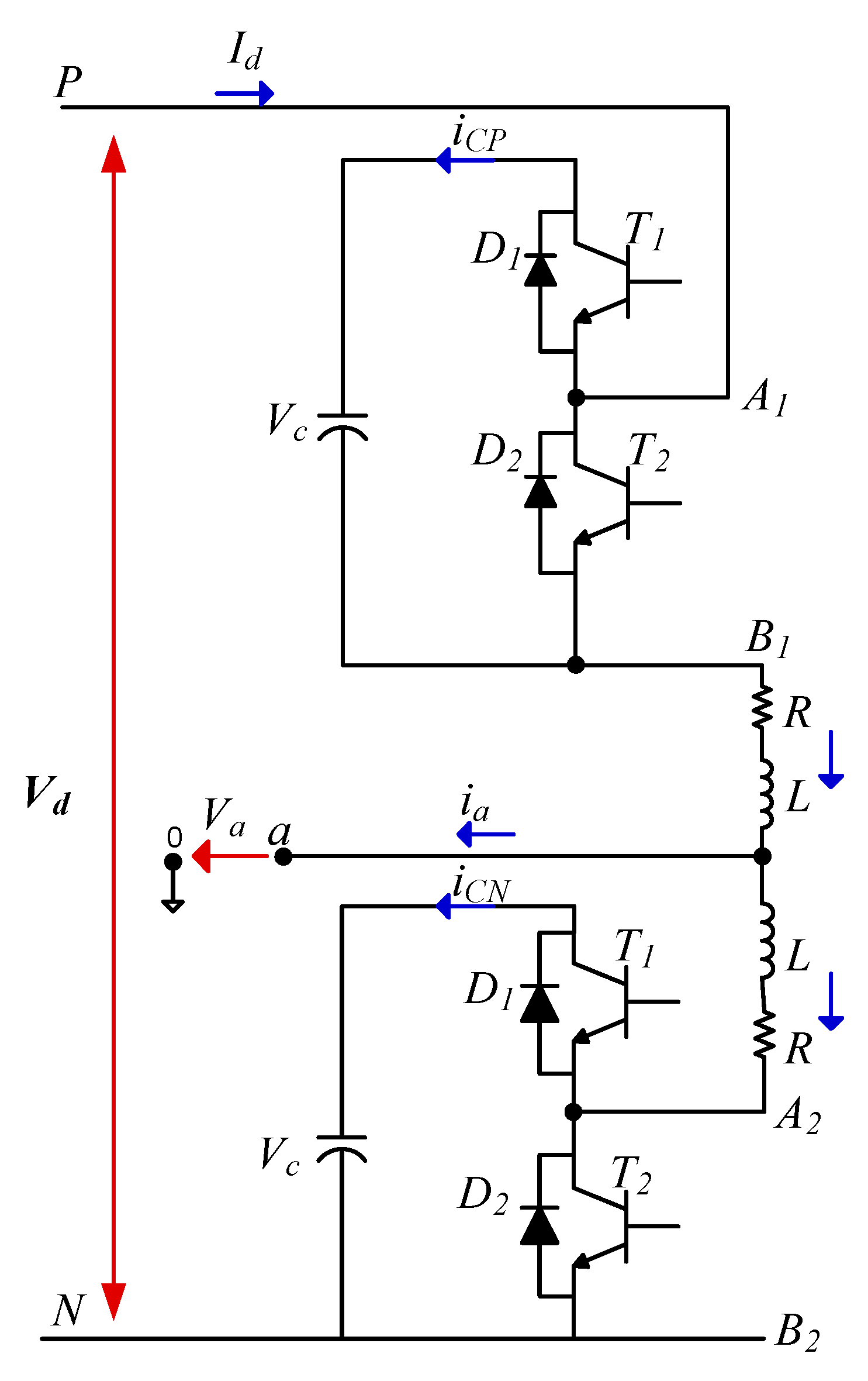
In order to simplify the analysis of the proposed network, the upper and lower arms of the MMC STATCOM are proposed to be equivalent to one power unit, which includes two IGBTs shunted by opposite-connected diodes and a capacitor forming a bidirectional chopper. Figure 8 shows a simplified one-phase equivalent circuit of the proposed MMC STATCOM. Point P in the circuit refers to the positive DC-link, while point N refers to the negative DC-link. In addition, the following assumptions are provided for more analysis,
- The DC-bus voltage Vd is constant without a ripple.
- There is a uniform distribution of the DC input current Id among the three phases.
- The switching losses in the main components of the circuit are ignored.
The terminal voltage ua and output current ia are assumed to be pure sinusoidal:
where U denotes the phase voltage peak value, I denotes the phase current peak value, ω is the angular frequency and φi is the phase shift between voltage and current.
For a symmetrical three-phase system, the phase current ia is divided equally between the two legs. Thus, the resulting share from the upper and lower legs can be identified as follows [27]:
where KI is the current coefficient that is expressed as
The differential equations of the upper and lower arms of Figure 8 can be introduced as follows:
where Vc is the voltage of the capacitor, s1 and s2 are the upper and lower leg switching functions, L denotes the AC inductance of the leg inductor and R is the equivalent resistance of the leg inductor.
4.1. DC-Link Capacitor
In this section, the calculations are only provided on the upper leg, as there is no difference between the upper and lower legs [28]. For more simplification, the calculations are performed taking into account the following assumptions:
- There is a small ripple in the DC capacitor voltage.
- Only the fundamental component of the switching function is considered.
In the steady-state condition, the upper leg switching function is defined as:
where M denotes the modulation index. From Equations (9), (12) and (16), the following formula is produced:
After integration, the following equation exists:
where VDC denotes the average DC voltage. The ripple in the current of the upper leg is described by the following formula:
By similarity, the ripple in the current of the lower leg is calculated as follows:
When the phase angle between the voltage and current φi equals ±90° during the static VAr generating condition and by ignoring the resistance of the inductor, Equation (19) will be converted to:
To obtain the maximum value of the peak-to-peak ripple voltage of the DC capacitor, Equation (21) is differentiated, which results in:
Accordingly, the capacitance of the DC capacitor can be defined as:
From Equations (14) and (20) it is clearly shown that the voltage ripple contains the fundamental and the second harmonic, which dramatically increases the rating of the capacitor, resulting in an increase in the total cost of the system. An accurate determination of the capacitance value in each sub-model must be taken into account, as a higher value of the capacitance leads to an increase in the total cost of the MMC converter, and on the other hand, a lower value increases the ripple level in the output voltage.
4.2. Design of SM Capacitance
The value of the capacitor affects the power quality indices such as the level of the THD and the voltage balance of the system. Many methods in literature have been introduced to determine the values of the capacitors. These methods can be divided into two main methods; the first is based on the idea that the average sum capacitor voltage per arm should be kept constant. The second is based on keeping constant the individual average capacitor voltages for the sub-modules for each arm. Both of the two methods are based on determining the required stored energy of the STATCOM-based MMC. The conclusion based on the literature review is that the first method is considered to be a better choice than the second one because using the first method improves the reliability of the system, and it is more convenient for the sub-module capacitor, as well as the semiconductor device, to perform under low voltage [20]. A general description of the first method has been presented.
Based on the energy storage demands of the converter, the capacitance of the SM can be determined. The minimum value of the capacitance of the SM is calculated as follows [29]:
where E denotes the lowest limit of energy storage for each arm. Due to the similarity between both arms, E for the upper arm can be expressed as reported in [25]:
where kmax refers to the capacitor voltage upper boundary. Typically, kmax = 1.1 is commonly used.
Finally, as ∆E and E are in direct dependence on the rated power of the converter, the demands for energy storage of the converter can be given as:
where W denotes the energy storage needed for each MVA rating. According to [24,30,31], the capacitance in each sub-module is selected so that the energy stored in all capacitors of the converter sub-modules is about 30–40 kJ/MVA. As the capacitance of the sub-module is not chosen yet, the ripple level of the sub-module capacitor voltage in the operating point is simply determined. There are two possible ways to obtain an anticipatory value of the voltage ripple. The first way is to assume a ripple level of ±10%, whereas the second way is based on assuming a value for the capacitor in each sub-module in the range, which achieved 30–40kJ/MVA stored energy, then performing simulation in the time domain to determine the level of the voltage ripple.
4.3. Design of Arm Inductance
Typically, the inductors used in the arms of the MMC are dry-type air-cored ones. The value of the inductance of the arm can be determined based on the way that the short circuits on the DC-side will be demonstrated. In addition, the inductance of the converter arm plays an important role in enhancing the characteristics of the inter-circulating current and limiting the fault current. Where bypass thyristors are used in the sub-modules or where they are separated using additional diode-based power modules, the AC sharing of the fault current on the DC-side does not need to be restricted to provide protection for the sub-modules’ anti-parallel diodes. The arm inductance helps in the limitation of the high frequency harmonics in the inter-circulating current and to provide a smooth control for the circulating current. A typical value of the arm inductance occurs around 0.05 p.u. [24].
On the other hand, when bypass thyristors are not used in the sub-modules or they are not separated using additional diode-based power modules, protection for the anti-parallel diodes on the DC-side of the converter have to be designed to protect the sub-modules from the high sharing from the AC-side to the fault current in the DC-side. Consequently, as the slow-acting breakers interrupt under this fault current, the arm inductors must restrict the current magnitude to give protection for the anti-parallel diodes, which act as a conduction path for the fault currents. The value of the arm inductance is determined using DC-fault actual time simulation, taking into account the interruption time of the circuit breakers, the time delay until fault detection and the strategy of performing the fault in the control system. Typically, the value of the inductance occurred in a range of 0.10–0.15 p.u.
Moreover, a short circuit between the terminals of the DC-buses is performed in order to present the most critical fault condition. In order to make a limitation on the short circuit current, the value of the arm inductance should be determined according to [29]:
where α (kA/s) denotes the maximum rising rate of the current. Based on (27), when the maximum rising rate is = 0.1(kA/µs) [29], for grid connected converters, the p.u. value of the arm inductance values are restricted at 0.3 pu for Double-Star Chopper Cell (DSCC-MMC), as well as for Single-Delta Bridge Cell (SDBC-MMC) configurations.
Larm = Vdc/2α
Consequently, modern metaheuristic techniques such as Atom Search Optimization (ASO) and Harris hawk’s optimization (HHO) have been proposed in this work for the optimization the of the values of capacitors and the coefficients of the DC voltage regulator of the MMC STATCOM, in order to minimize the total harmonic distortion (THD) in the power system under consideration, keeping the ripple voltage in the allowable ranges and obtaining minimum current circulation within the converter.
5. Problem Formulation
Usually, in electric power systems, shunt compensating devices are used for voltage and reactive power control. A MATLAB model for the system under study is shown in Figure 9. The parameters of each component in the system are summarized in Table 2. The system under study compromises the utilization of the MMC STATCOM, which is increasingly used in modern electric networks. The proposed MMC STATCOM is based on full-bridge MMC to form 22 modules per phase power converter. The STATCOM can produce or take reactive power from the grid. The transfer of both types of reactive power is obtained via phase reactance.
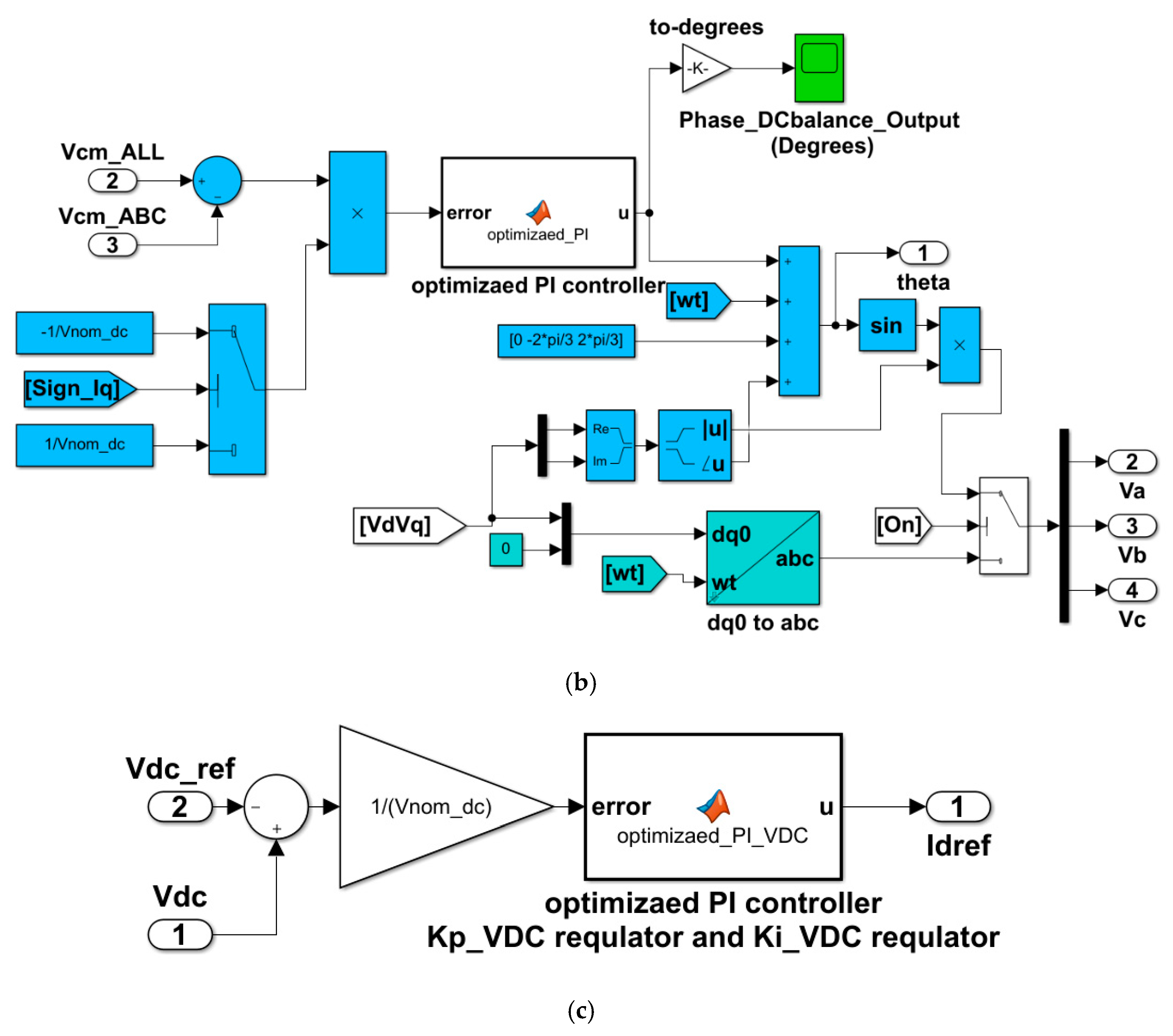
The proposed MMC generates a three-phase voltage, which has the same phase as that of the grid voltage at the point of coupling. When the amplitude of the voltage generated from the MMC is lower than the grid voltage amplitude, the STATCOM performs like inductance and absorbs reactive power from the grid utility. When the amplitude of the MMC voltage is higher than that of the bus of common coupling, the STATCOM works like a capacitor and reactive power will be injected into the grid. The control circuit of the MMC is shown in Figure 10a. The controller of the high voltage side includes a phase-locked loop (PLL), transformation and measurement blocks, DC-bus voltage regulator and current regulator. Meanwhile, the controller of the low voltage side includes individual and phase balancing controllers of the DC-bus voltage, which are responsible for generating the control signals for producing the pulses applied to the gates of the transistors. Moreover, the optimized controller for phase balancing based on the HHO or ASO optimization techniques is shown in Figure 10b, and the optimized controller of DC voltage based on the HHO or ASO optimization techniques is shown in Figure 10c.
As discussed in Section 2, the impact of the second component harmonic voltage of the module capacitor on the MMC impedance behavior is expressed. Optimal determination of the value of the module capacitor results in an improvement in the second component of harmonic in the voltage of the module capacitor. Moreover, by reducing the capacitance value, in increase in the second component of harmonic voltage will be observed. Furthermore, it is easy to find that with an increase in the magnitude of the module capacitor voltage second harmonics, an effective increase is observed in the magnitude of the impedance response at low frequencies, but there is no change noticed in positive-sequence. Starting from the introduced explanation, the optimal determination of the module capacitor can be addressed as the design of the impedance of the MMC. However, if a stable performance of the STATCOM is desired, the proposed design should give the minimum demands for energy storage and filtering ripples arising in the capacitance voltage, which shape the constraints of controlling module capacitance to produce an optimal impedance response. Therefore, this paper proposes that the value of the capacitor should be selected to be optimized to reduce the THD using the HHO and ASO algorithm. The objective function to achieve optimal capacitor values leading to the minimum quadratic error of the THD can be calculated as follows:
Moreover, to achieve the optimal values of both Kp and Ki for each PI controller, which lead to a minimum quadratic error, the objective function can be calculated as follows:
where e. is the error signal between the desired and the typical signals and is fed to the PI controller.
The objective function to minimize F can be determined as follows:
where F is the summation of the F1 and F2.
Minimize {F(C,(Kp,Ki)VDC,(Kp,Ki)phase balancing}
6. Proposed Optimization Methods
In the past decades, with the increasing development in the fields of society, economy and industry, numerous complicated and hardly-solved optimization problems have arisen in all fields. Recently, metaheuristic techniques of optimization have been widely implemented to solve complicated engineering problems, as they possess high capabilities of exploration and exploitation to reach global solutions in a short time when compared with traditional optimization methods [31,32,33,34].
Taking into account the No Free Lunch Theorem of Optimization [35], the best solution of different optimization problems cannot be fulfilled based on one optimization technique. Based on this theorem, the field of creating and developing better optimization algorithms is still active and full of great achievements. As a result of these achievements, a recent swarm algorithm inspired by physics, called Atom Search Optimization (ASO), is proposed for tackling the optimization problem provided in this study. ASO presented superior performance over conventional and recent optimization techniques when validated on numerous mathematical problems. In addition, the proposed ASO algorithm provided a successful performance when utilized in the optimization problem of hydrogeologic parameter estimation.
In a related context, like the most of existing optimization methods, the searching process in the proposed ASO algorithm is performed in two phases; exploration and exploitation stages [30]. In the first phase, the optimization algorithm should make utilization and promotion of the randomly initialized operators for the deep exploration of the optimal solution within the search space. Thus, the exploratory behavior of a well-developed optimization algorithm should be randomly enriched to generate more random solutions to different areas of the addressed problem formed in the early stages of the research process [36].
6.1. Harris Hawk’s Optimization (HHO)
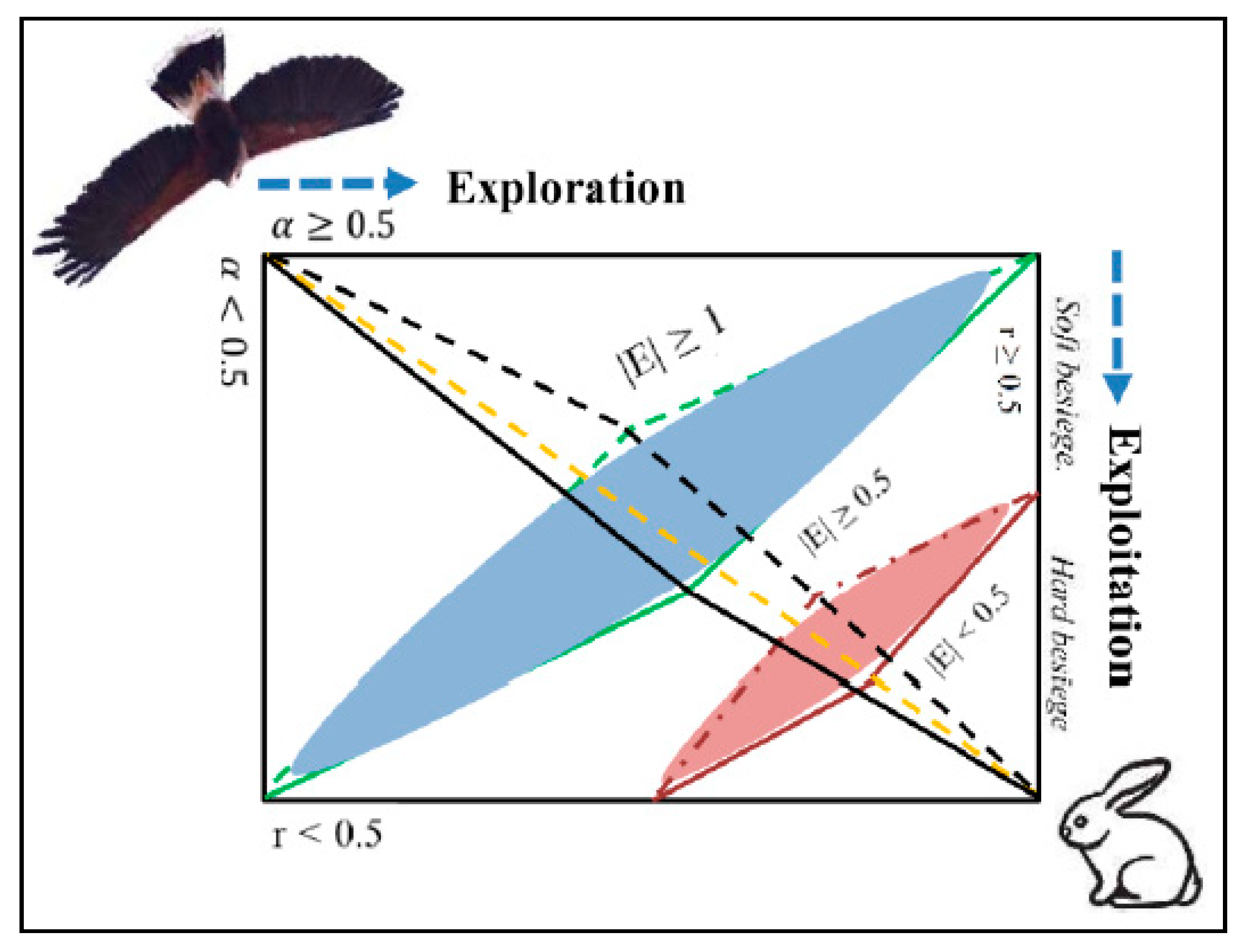
The HHO algorithm was developed in 2019, which in its operation mimics the behavior of the hunting of the Harris hawks, a group of intelligent birds that live in the USA [32,33]. The hunting manner of these intelligent birds depends on surprise. A group of hawks appear to their prey (rabbits) from different sides at the same time to surprise it, at which point the best-fit hawk of the group (the leader) surrounds it. Mathematically, the technique of catching the prey of the hawks can be divided into three stages: (i) the exploration stage, (ii) the stage of transition from exploration to exploitation and finally (iii) the exploitation stage. The first phase of the attack is the most important as it determines the way that the hawks will act. Firstly, all hawks sit randomly in a high place to give them a good chance of observing the environment and wait for their chase. When the prey appears in the surrounding area, the hawks may attack it in several possible manners, and only the leader will decide the way of attack. All hawks might cooperate and surround the prey, or the leader will give the opportunity to one of them, and it will depend on the behavior of the prey to escape. For each of the two possible tactics, the hawks may take their places depending on the location of the neighboring hawk as expressed in (31) or be distributed randomly as described in (32):
where X(t) is the position of the hawks at the present iteration t; X(t+1) is a vector of the new positions of the hawks in the next iteration; Xbest(t) is the position of the chase (rabbits); and α, β, ψ, φ and τ are randomly distributed numbers in the range from 0 to 1. UB and LB denote the upper and lower limits of the position variables. Xrand(t) denotes a hawk, which is randomly selected from the present population, and Xavg(t) denotes the mean position of the hawks. The average position of the hawks is determined as follows:
where Xi(t) denotes the position of each hawk in iteration t and N indicates the number of hawks. Depending on the energy of the prey during the escaping process, HHO can make a transition from exploration to exploitation. The energy of the prey (rabbit) is determined as follows:
where, E0 denotes the initial energy in each iteration, which is randomly taken from [−1, 1], and T presents the maximum iterations.
As the hawks have detected the prey as explained in the previous stages, they have to make a sudden attack, which depends on the probability of escape. In the mathematical modelling, the probability of escape r will be <0.5 for a successful escape and r ≥ 0.5 if the prey unsuccessfully gets away. Depending on the way that the prey will take during escape, the hawks will carry out a soft or hard siege. Regardless of the energy of escape, a hard or soft siege will occur. When |E| ≥ 0.5 and r ≥ 0.5, the prey has enough energy to make random jumps but fails to escape. During these miserable attempts, the hawks surround the prey until it is exhausted by its force and then suddenly attack it. Thus, the soft siege is described as:
where ΔX(t) denotes the difference between the prey’s position and the position of the hawks in the present iteration. J is the strength of the prey’s random escape.
When |E| < 0.5 and r ≥ 0.5, as the prey has no energy to escape, a hard siege will be performed. Accordingly, the hawks hardly circle the prey to execute a surprise attack. Therefore,
6.2. Atom Search Optimization (ASO)
Atom search optimization is a novel physics-based method for global optimization problems [34,35]. ASO is a population-based technique, which imitates the motion of atoms subjected to interactions and other constraint forces [33,34]. The total forces of interaction that affect the ith atom in the dth dimension are described as follows:
where randj is a number randomly distributed in the range [0, 1] and Kbest is a group of K atoms having the best values fitness function. The value of K has to be decreased gradually as the iterations advance, to let ASO perform more exploitation in the latest iterations, as shown in the following expression:
where N denotes the total number of atoms forming an atomic structure, t denotes the present iteration, and T is the total number of iterations. The interaction force presents the gradient of the potential Lennard-Jones (L-J) and is described in the following formula [29]:
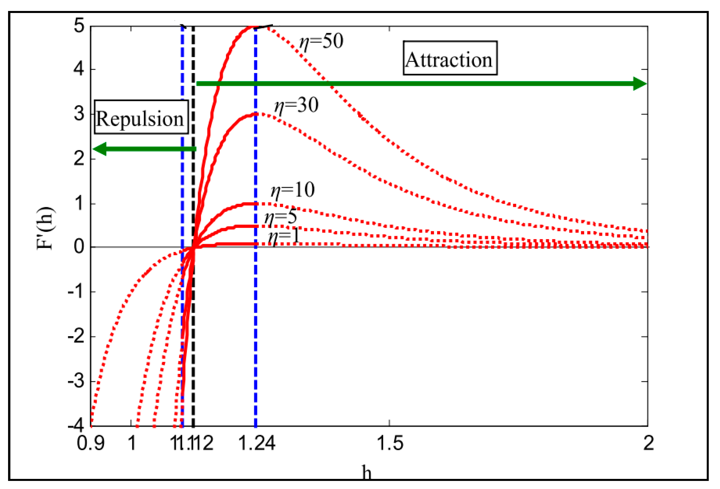
where η(t) presents the depth function, which controls the regions of attraction and repulsion; hij(t) is the ratio between the distance between two atoms rij and the scaled distance between them σ(t).
where α denotes the depth weight. The function of the force of interaction under different values of η with respect to a variable scaled distance (h changed from 0.9 to 1) is presented in Figure 12.
Equation (42) presents the expression of the scaled distance between any two atoms i and j:
where hmin and hmax describe the upper and lower limits of the distance (h), respectively, and are determined by the following formula:
where g0 and u denote the lower and upper limits, respectively. g(t) denotes a drift factor to give the algorithm the ability to transform from the exploration to the exploitation stage.
Presuming that there is a covalent bond between each atom in ASO and the best one, the constraint force resulting from this combination be expressed as follows:
where
where denotes the location of the best atom in the dth dimension, λ(t) indicates the Lagrangian multiplier, and β denotes a multiplier weight. After defining the forces of interaction and L-J potential resultant constraint force, the acceleration, to which the ith atom is projected in the dimension d and iteration t, is determined as follows:
where denotes the mass of the atom number i in the dimension d of iteration t, and is determined from the value of its fitness function as described below:
where
Finally, the velocity of the ith atom in the search space and the new position acquired at the next iteration (t+1) can be described by the following formulas:
7. Results and Discussion
The simulation results have been obtained to validate the effectiveness of the proposed optimization techniques in determining the optimal values of the capacitance and the parameters of the DC voltage regulator. Moreover, to validate the accuracy of the those obtained from the results, these values have been applied to the system under study under the integration of nonlinear loads and the condition of three-phase imbalance. The performance of the MMC STATCOM in the two study cases has been introduced in the simulation results.
7.1. Nonlinear Load Case Study
For the simulation purpose, a dedicated software program for the optimal estimation of the capacitor value, Kp and Ki, is developed in MATLAB/Simulink. The results of the proposed methods are compared with those of the conventional particle swarm optimization (PSO) [37,38,39]. The design parameters and the limits of the optimized variables are identical for the all optimization techniques proposed in this paper. The end value of iterations has been adjusted at 10 iterations and the search agents are proposed to be 10 agents. The convergence curves of the optimization algorithms are shown in Figure 13. The detailed results of the optimization process for ASO, HHO and PSO are summarized in Table 3. As shown from Figure 13, the HHO algorithm reached the optimum values of the capacitors and coefficients for the PI controllers within two iterations, and ASO reached the best value of the fitness function after four iterations. While the conventional PSO algorithm is the slowest among them, moreover, its finding of the best value of the fitness function (F) is achieved after eight iterations, and it is worse than that with the HHO and ASO. Both of the proposed algorithms were able to obtain convergent results and satisfactory results to improve the voltage and reduce the THD of the current in the studied network, but HHO reached the optimum solution in less time.
The optimal values for the capacitors of MMC and PI controller constants obtained using HHO and ASO have been applied to the network under study. The profile of the MMC DC voltage for both algorithms is shown in Figure 14, where it can be noticed that stability of the DC voltage is achieved in both cases.
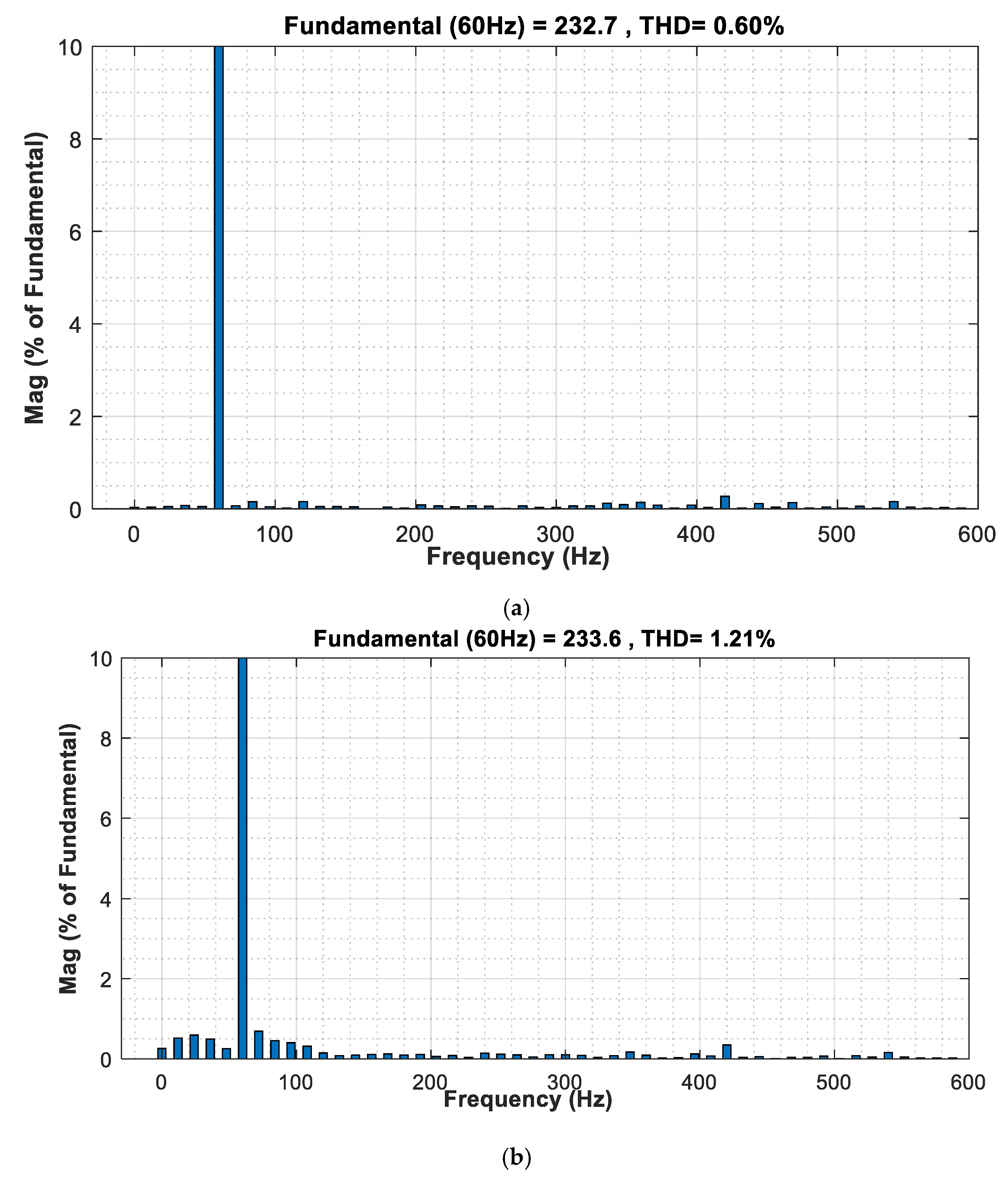
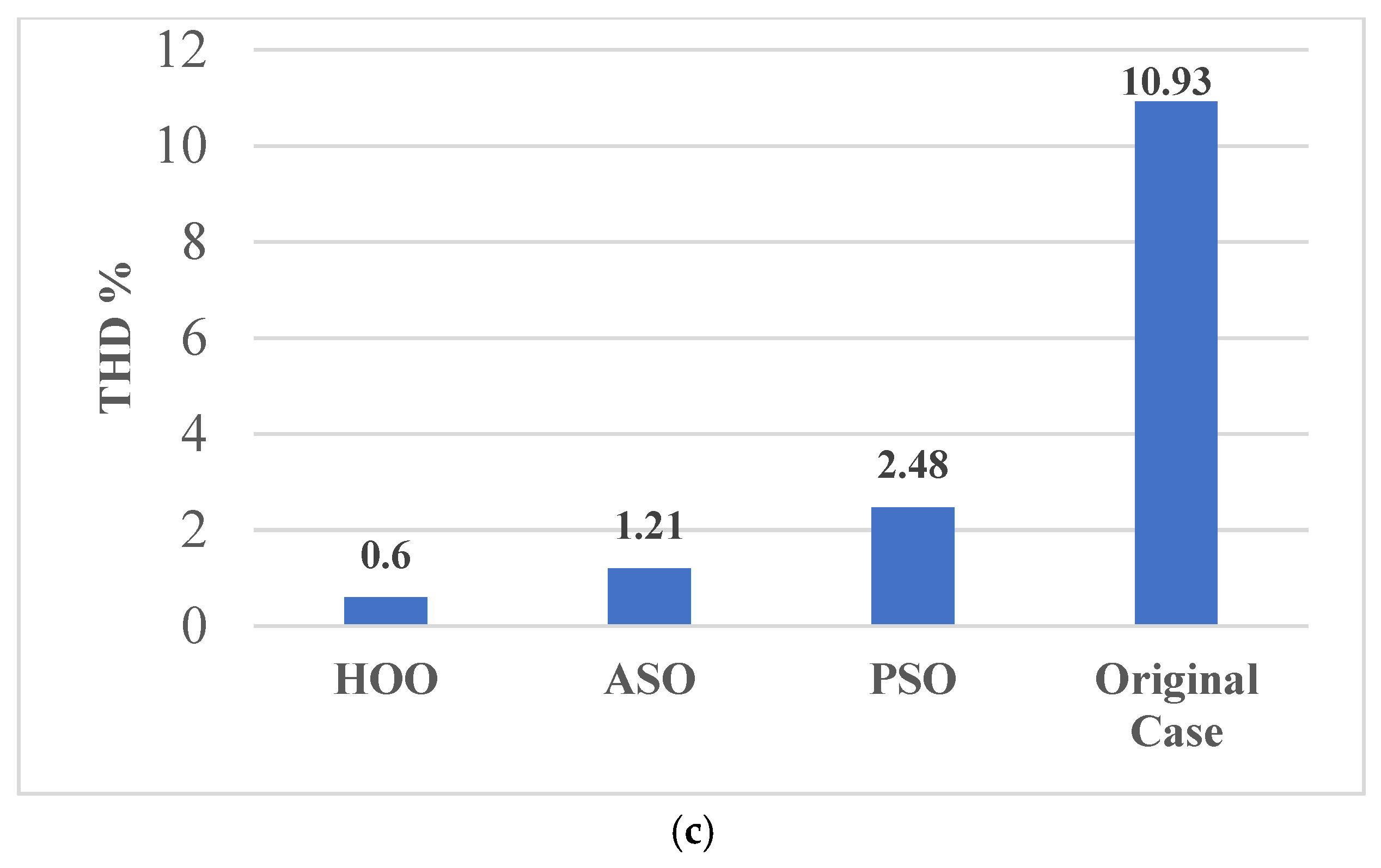
The THD of the current in the original state before optimization was 10.93% in the moment of the connecting MMC STATCOM, as shown in Figure 15, while the THD analysis of the grid current is shown in the Figure 16a, where the value of the THD is decreased to 0.60% with the optimal values of the capacitor converters and the optimal values of the PI controllers as determined using HHO. Moreover, the THD of the current with the optimal values of the capacitor converters and the optimal values of the PI controllers as determined using the ASO algorithm decreased to 1.21%, as shown in Figure 16b. Additionally, Figure 16c shows a comparison between the THD analysis of the current grid with different methods (HHO, ASO and PSO).
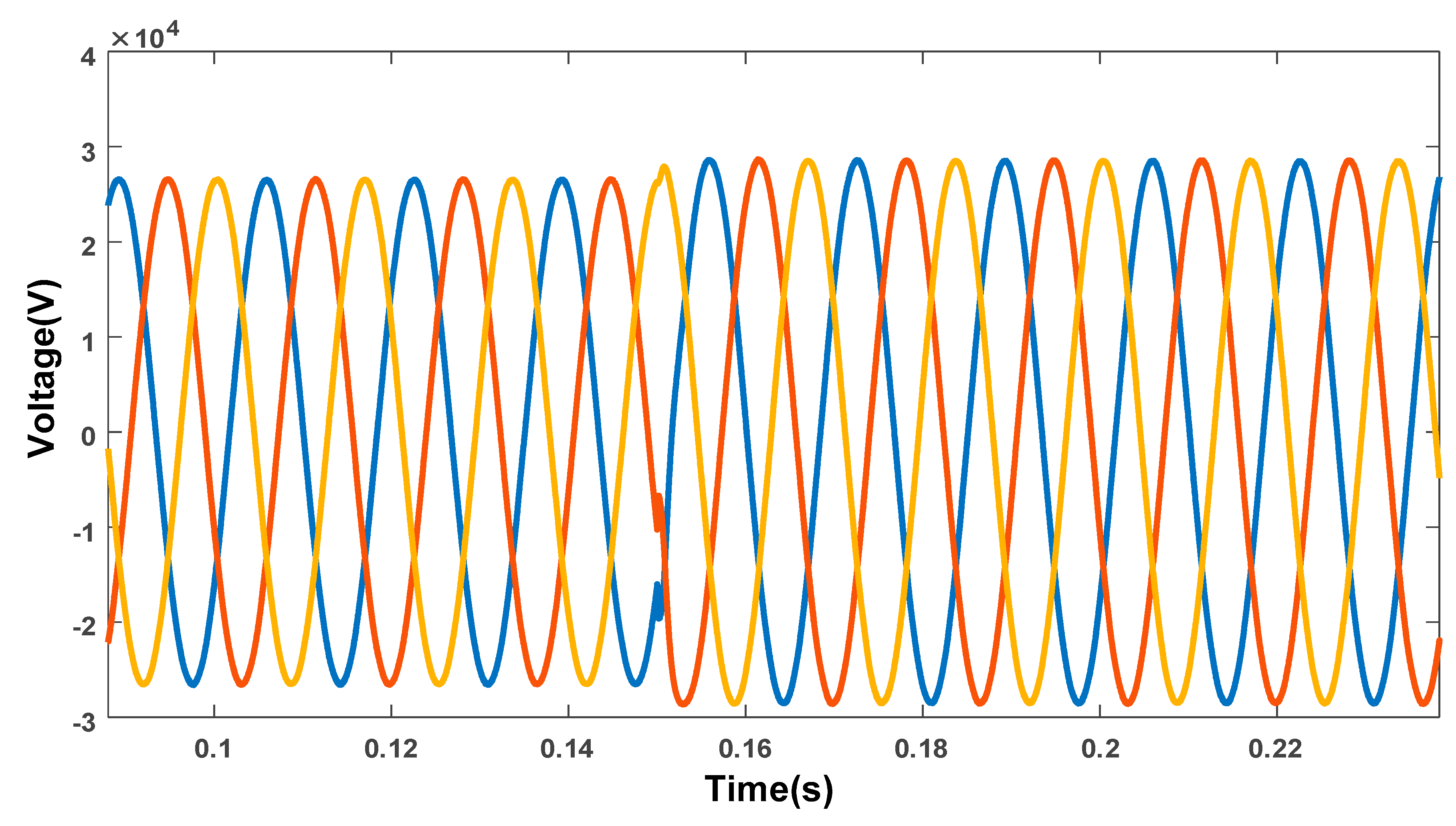
The improvement of the voltage profile by compensating the reactive power is one of the main prospective results of MMC STATCOM. In order to examine the operation of the MMC STATCOM with the reactive power command, Qref is changed from (−5 MVAr); in this case the STATCOM operates in the inductive mode, to (+10 MVAr), where the STATCOM operates in the capacitive mode.
The grid side voltage and current of the MMC STATCOM are shown in Figure 17. As shown from Figure 17, when the set-point of the reference reactive power changed at 0.15 s, the current drawn from the grid steps from lagging the grid voltage by 90 degrees to leading the voltage by 90 degrees. The control system of the STATCOM introduces a rapid reaction for modifying the terminal voltage of the inverter in order to produce 10 MVAr of reactive power (capacitive mode). The load current and output voltage are represented in Figure 18.
The active and reactive power with the connection of the MMC STATCOM is presented in Figure 19a,b respectively. From the figure, a high dynamic performance with acceptable raise time has been achieved for the reactive power variation. Moreover, the three-phase voltage of the converters in this case of study is shown in Figure 20.
7.2. Unbalanced Load Case Study
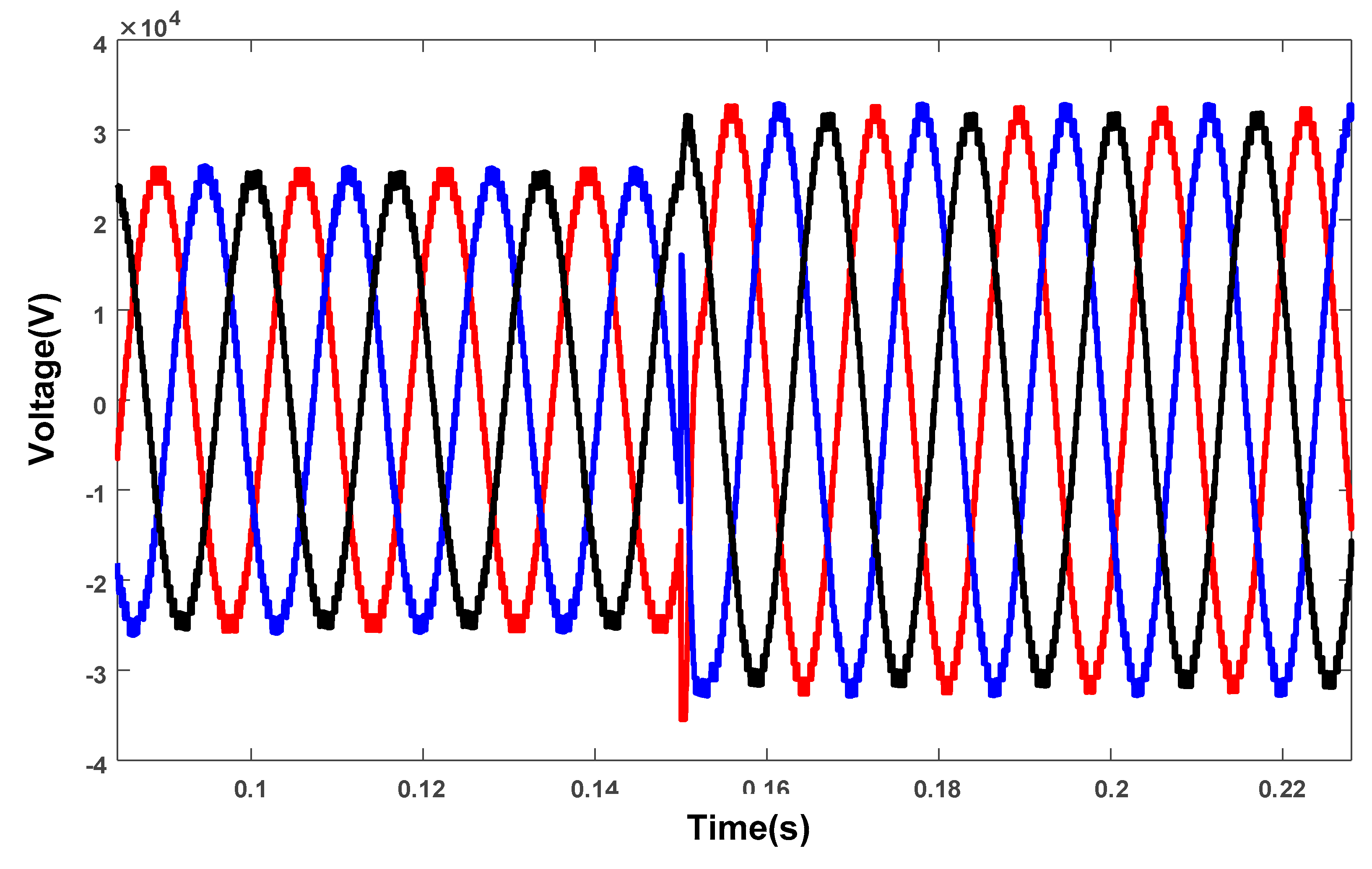
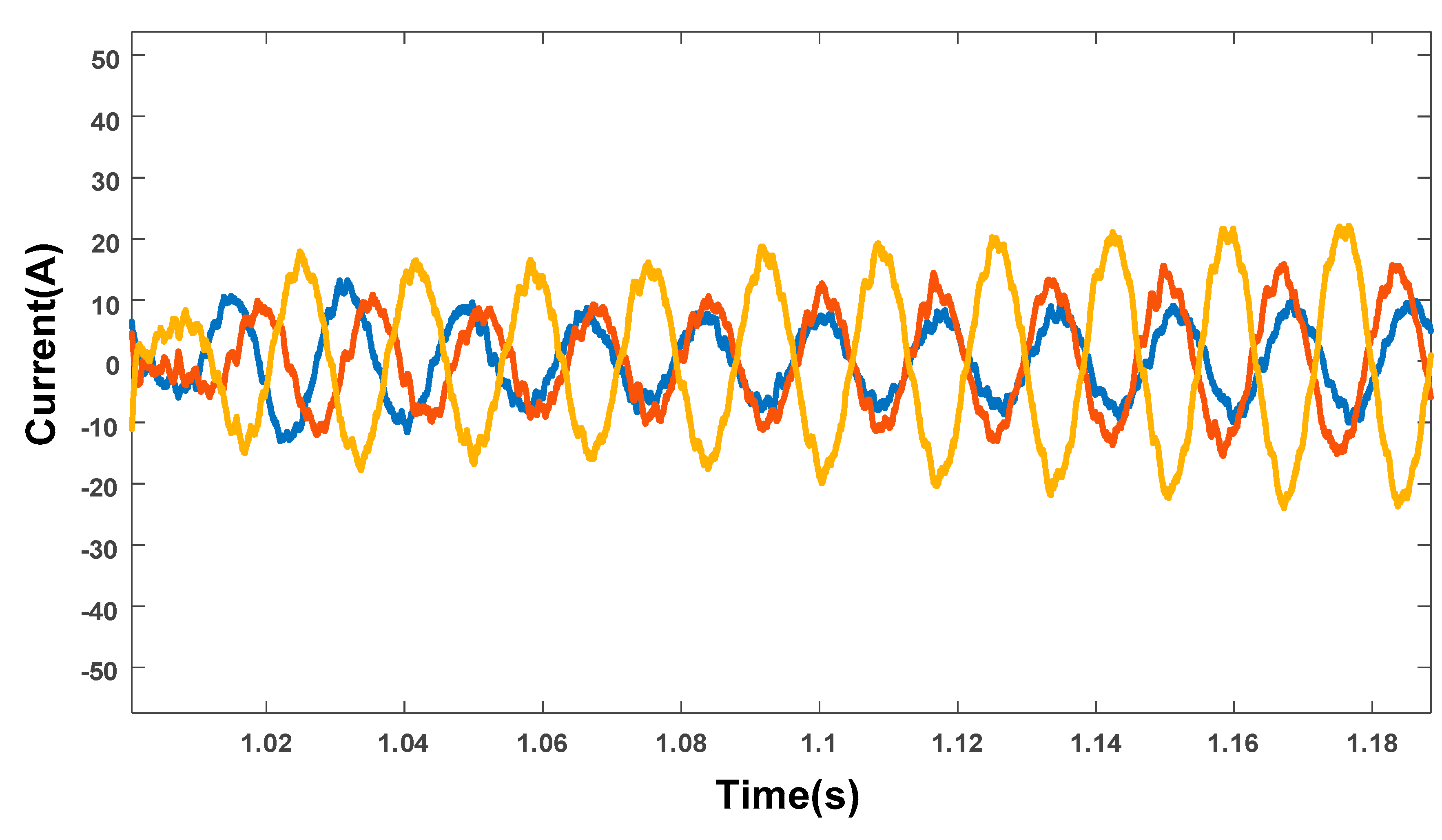
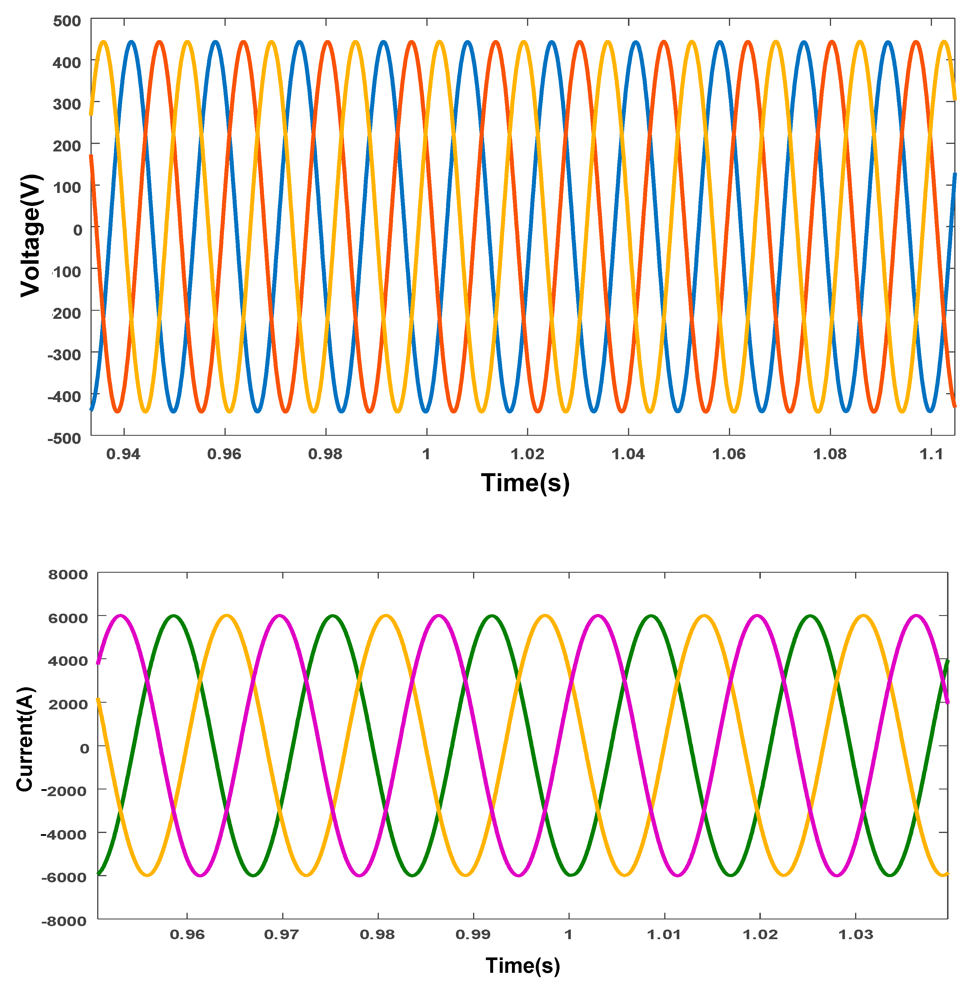
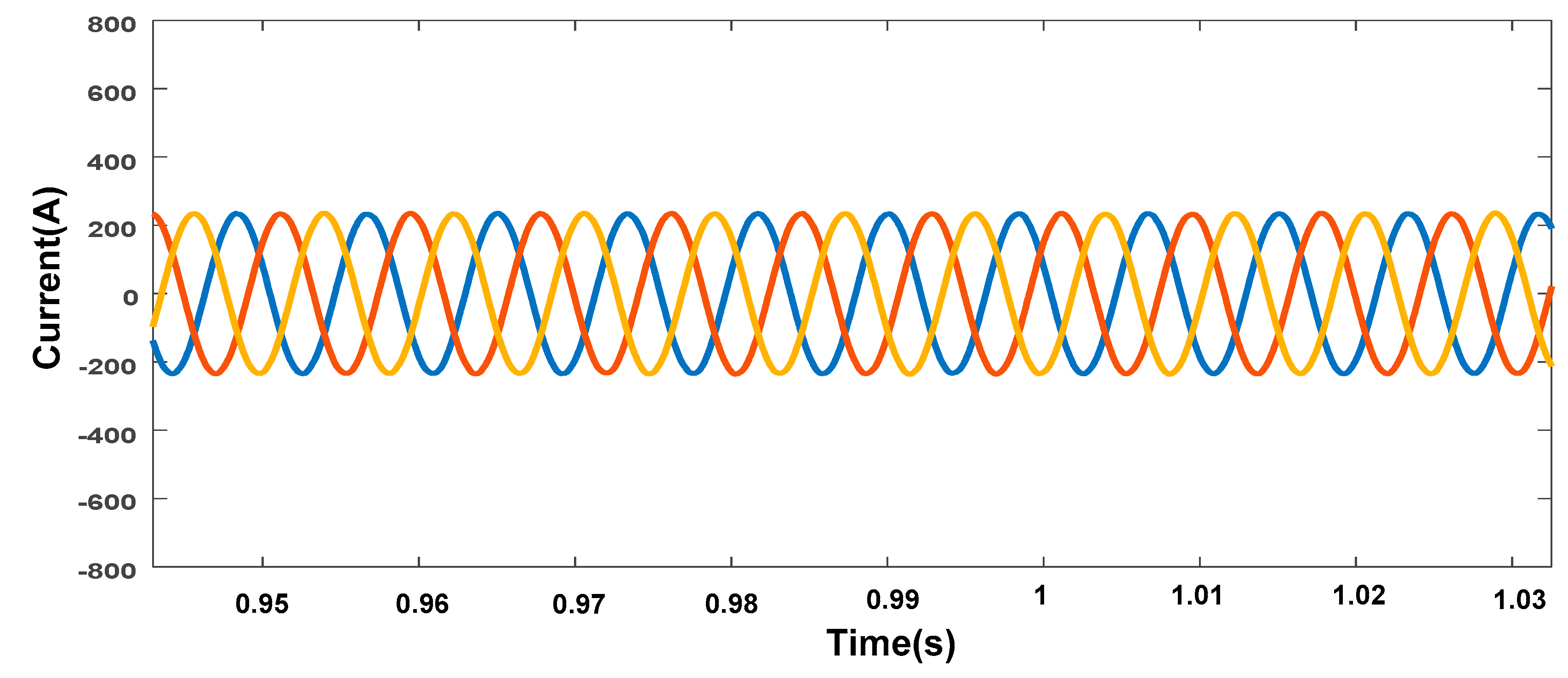
For more validation of the proposed configuration, the system has been tested under the case of unbalanced load. In this case of study, the load on phase C has been assumed to be changed at 1 s by 3 s, and the current at the grid side with imbalanced load is shown in Figure 21. The effectiveness of the proposed control scheme based on the optimization technique of HHO is examined. The voltages and currents at the load side are shown in Figure 22. Figure 23 shows the grid side voltages and currents, which indicate a balance in the grid currents and voltages. Moreover, Figure 24 shows the DC link voltage of the MMC for this case of study. As observed from the figures, in the case of imbalanced load, the proposed MMC STATCOM with the optimal design based on the optimization algorithms was able to maintain the voltage and currents as balanced as possible. Moreover, the maintenance of the voltage in the DC-link, constant without fluctuations, was also desired, and it has been achieved as observed in Figure 24.
8. Conclusions
The compensation of harmonics is a major task in the modular multilevel converter (MMC). The Full-Bridge MMC block with 22 modules per phase is presented in this paper. The optimal design of the MMC capacitor and the optimized parameters of the PI controller were determined using HHO and ASO techniques. Moreover, two realistic representative cases of studies were designed and tested: nonlinear and imbalanced loads. The THD of the current before applying the proposed algorithm was 10.97%, where with the optimal values of the capacitor converters, the THD decreased to 0.60% by using the HHO algorithm, whereas THD decreased to 1.21% using the ASO. The results show that with the application of the MMC STATCOM, the voltage and current load are rapidly adjusted in the case of the imbalanced load. Moreover, the voltage DC-link of the converter has a stability value, and this will reduce the value of the current circulation within the converter. In the two cases of nonlinear and imbalanced loads, the voltage in the DC-link has a stabilized value, and this, in turn, improves the performance of the control system and the power quality indicators in the studied network. In addition, the application of the MMC in grid-connected photovoltaic and wind energy systems and micro grids is also an important issue for our future works. In spite of this, the study of this topic is outside of the framework of this paper, and it can be covered in future works. Finally, the authors would like to remark that, due to the lack of laboratory equipment and apparatus with the high voltage rating, the real time implementation of the proposed algorithm was not performed. However, in future work, one of the aspects of our work will be to experimentally implement the presented control system. Additionally, future work will present the application of other control algorithms to achieve an improvement of the overall system performance.
Author Contributions
Conceptualization, A.A.Z.D. and R.A.; Data curation, H.M.S. and Z.M.A.; Formal analysis, A.A.Z.D. and H.M.S.; Methodology, T.E., A.A.Z.D. and R.A.; Resources, A.A.Z.D., R.A. and Z.M.A.; Software, H.M.S.; Supervision, A.A.Z.D.; Validation, T.E. and A.A.Z.D.; Visualization, A.A.Z.D., H.M.S. and Z.M.A.; Writing—original draft, T.E., A.A.Z.D., R.A. and H.M.S.; Writing—review & editing, A.A.Z.D., R.A. and Z.M.A. All authors together organized and refined the manuscript in the present form. All authors have read and agreed to the published version of the manuscript.
Funding
This research received no external funding.
Conflicts of Interest
The authors declare no conflict of interest.
References
- Sandeer, K.N. Power Quality Issues and its Mitigation Techniques. Master’s Thesis, National Institute of Technology Rourkela, Orissa, India, 2014. [Google Scholar]
- Kartashov, I.I.; Tulsky, V.N.; Shamonov, R.G.; Sharov, Y.V.; Nasyrov, R.R. Control of Power Quality, 2nd ed.; MPEI: Moscow, Russia, 2017; pp. 347–350. [Google Scholar]
- Shahewar, S.; Malthon, R.; Sushmalatha, S. Power Quality Issues and Their Mitigation Technologies. Int. J. Ind. Electron. Electr. Eng. 2014, 2, 55–61. [Google Scholar]
- Tejinder, S.S.; Lakhwinder, S. Comparative Analysis of Custom Power Devices for Power Quality Improvement in Non-linear Loads. In Proceedings of the 2015 2nd International Conference on Recent Advances in Engineering & Computational Sciences (RAECS), Chandigarh, India, 21–22 December 2015. [Google Scholar] [CrossRef]
- Wankhede, M.V.; Chandrakar, V.K. Static Synchronous compensator (STATCOM) for the improvement of Electrical System Performance with Non-linear load. Int. J. Power Syst. 2016, 1, 27–32. [Google Scholar]
- Devendra, M.H.; Vinod, K.C. Harmonic domain modeling of Space vector based STATCOM. Energy Power Eng. 2016, 8, 195–203. [Google Scholar]
- Martinek, R.; Bilik, P.; Baros, J.; Brablik, J.; Kahankova, R.; Jaros, R.; Danys, L.; Rzidky, J.; Wen, H. Design of a Measuring System for Electricity Quality Monitoring within the SMART Street Lighting Test Polygon: Pilot Study on Adaptive Current Control Strategy for Three-Phase Shunt Active Power Filters. Sensors 2020, 20, 1718. [Google Scholar] [CrossRef] [PubMed] [Green Version]
- Leon, M.T.; Xiaojie, S. Multilevel Power Converters. In Power Electronics Handbook, 2nd ed.; Rashid, M.H., Ed.; Elsevier: San Diego, CA, USA, 2018; pp. 385–416. [Google Scholar] [CrossRef]
- Corzine, K.; Familiant, Y. A new cascaded multilevel H-bridge drive. IEEE Trans. Power Electron. 2002, 17, 125–131. [Google Scholar] [CrossRef]
- Kolb, J.; Kammerer, F.; Braum, M. Dimensioning and design of a modular multilevel converter for drive applications. In Proceedings of the IEEE 15th International Power Electronics and Motion Control Conference, Novi sad, Serbia, 4–6 September 2012. [Google Scholar]
- Dekka, A.; Bin, W.; Zargari, N.R.; Fuentes, R.L. A space-vector PWM-based voltage-balancing approach with reduced current sensors for modular multilevel converter. IEEE Trans. Ind. Electron. 2016, 63, 2734–2745. [Google Scholar] [CrossRef]
- Hammond, P.W. Four-quadrant AC-AC Drive and Method. U.S. Patent 6,166,513, 26 December 2000. [Google Scholar]
- Aiello, M.F.; Hammond, P.W.; Rastogi, M. Modular Multi-Level Adjustable Supply with Series Connected Active Inputs. U.S. Patent 6,236,580, 22 May 2001. [Google Scholar]
- Aiello, M.F.; Hammond, P.W.; Rastogi, M. Modular Multilevel Adjustable Supply with Parallel Connected Active Inputs. U.S. Patent 6,301,130, 9 October 2001. [Google Scholar]
- Marquardt, R. Stromrichterschaltungen Mit Verteilten Energiespeichern. German Patent DE 10,103,031, 24 January 2001. [Google Scholar]
- Shi, X.; Tolbert, L.; Wang, F. Modular multilevel converters with integrated arm inductors for high quality current waveforms. In Proceedings of the IEEE Energy Conversion Congress and Exposition, Mile High City, CO, USA, 15–19 September 2013. [Google Scholar]
- Quraan, M.; Yeo, T.; Tricoli, P. Design and control of modular multilevel converters for battery electric vehicles. IEEE Trans. Power Electr. 2015, 31, 507–517. [Google Scholar] [CrossRef]
- Thitichaiworakorn, N.; Hagiwara, M.; Akagi, H. Experimental verification of a modular multilevel cascade inverter based on double-star bridge-cells (MMCI-DSBC). IEEE Trans. Ind. Appl. 2014, 50, 509–519. [Google Scholar] [CrossRef]
- Nor Shahida, H.; Norzanah, R.; Dygku, A.A.; Osman, A.H. Reviews on multilevel converter and modulation techniques. Renew. Sustain. Energy Rev. 2017, 80, 163–174. [Google Scholar]
- Nasyrov, R.R.; Aljendy, R.I.; Abdelaziz, A.L.; Diab, A.A.Z. Enhancement of Power Quality with Hybrid Distributed Generation and FACTS Device. IETE J. Res. 2019, 1–12. [Google Scholar] [CrossRef]
- Ufa, R.; Gusev, A.; Diab, A.A.Z.; Suvorov, A.; Ruban, N.; Andreev, M.; Askarov, A.; Rudnik, V.; Abdalla, O.; Ali, Z.M.; et al. Analysis of application of back-to-back HVDC system in Tomsk electric power system. Energy Rep. 2020, 6, 438–444. [Google Scholar] [CrossRef]
- Mohamed, I.S.; Rovetta, S.; Do, T.D.; Dragicević, T.; Diab, A.A.Z. A neural-network-based model predictive control of three-phase inverter with an output LC filter. IEEE Access 2019, 7, 124737–124749. [Google Scholar] [CrossRef]
- Nasyrov, R.R.; Aljendy, R.I.; Diab, A.A.Z. Adaptive PI controller of active power filter for compensation of harmonics and voltage fluctuation based on particle swarm optimization (PSO). In Proceedings of the 2018 IEEE Conference of Russian Young Researchers in Electrical and Electronic Engineering (EIConRus), Moscow, Russia, 29 January–1 February 2018; pp. 719–724. [Google Scholar]
- Marquardt, R. Modular multilevel converter topologies with dc-short circuit current limitation. In Proceedings of the IEEE 8th International Conference on Power Electronics and ECCE Asia (ICPE & ECCE), Jeju, Korea, 29 may–2 June 2011. [Google Scholar]
- Sharifabadi, K.; Harnefors, L.; Nee, H.P.; Norrga, S.; Teodorescu, R. Design, Control, and Application of Modular Multilevel Converters for HVDC Transmission Systems; John Wiley & Sons: Hoboken, NJ, USA, 2016. [Google Scholar] [CrossRef]
- Cupertino, A.; Farias, J.; Pereira, H.; Seleme, S.; Teodorescu, R. Comparison of DSCC and SDBC Modular Multilevel Converters for STATCOM Application During Negative Sequence Compensation. Ieee Trans. Ind. Electron. 2019, 66, 2302–2312. [Google Scholar] [CrossRef]
- Sajedi, S.; Farrell, M.; Basu, M. DC side and AC side cascaded multilevel inverter topologies: A comparative study due to variation in design features. Electr. Power Energy Syst. 2019, 113, 56–70. [Google Scholar] [CrossRef]
- Siemaszko, D.; Antonopoulos, A.; Ilves, K.; Vasiladiotis, M.; Angquist, L.; Nee, H.P. Evaluation of control and modulation methods for modular multilevel converters. In Proceedings of the IEEE International Power Electronics Conference, Sapporo, Japan, 21–24 June 2010. [Google Scholar]
- Yang, X.; Li, J.; Fan, W.; Wang, X.; Zheng, T. Research on Modular Multilevel Converter Based STATCOM. In Proceedings of the 2011 6th IEEE Conference on Industrial Electronics and Applications, Beijing, China, 21–23 June 2011; pp. 2569–2574. [Google Scholar]
- Ilves, K.; Norrga, S.; Harnefors, L.; Nee, P. On energy storage requirements in modular multilevel converters. Ieee Trans. Power Electron. 2014, 29, 77–88. [Google Scholar] [CrossRef]
- Jacobson, B.; Karlsson, P.; Asplund, G.; Harnefors, L.; Jonsson, T. VSC-HVDC transmission with cascaded two-level converters. In Cigré Session; CIGRE: Paris, France, 2010; pp. B4–B110. [Google Scholar]
- Bairathi, D.; Gopalani, D. A Novel Swarm Intelligence Based Optimization Method: Harris’ Hawk Optimization. In Proceedings of the International Conference on Intelligent Systems Design and Applications, Vellori, India, 6–8 December 2018. [Google Scholar]
- Heidari, A.A.; Mirjalili, S.; Faris, H.; Aljarah, I.; Mafarja, M.; Chen, H. Harris hawks optimization: Algorithm and applications. Future Gener. Comput. Syst. 2019, 97, 849–872. [Google Scholar] [CrossRef]
- Zhao, W.; Wang, L.; Zhang, Z. A novel atom search optimization for dispersion coefficient estimation in groundwater. Future Gener. Comput. Syst. 2019, 91, 601–610. [Google Scholar] [CrossRef]
- Zhao, W.; Wang, L.; Zhang, Z. Atom search optimization and its application to solve a hydrogeologic parameter estimation problem. Knowl.-Based Syst. 2019, 163, 283–304. [Google Scholar] [CrossRef]
- Wolpert, H.; Macready, G. No free lunch theorems for optimization. IEEE Trans. Evol. Comput. 1997, 1, 67–82. [Google Scholar] [CrossRef] [Green Version]
- Yang, S. Review of meta-heuristics and generalised evolutionary walk algorithm. Int. J. Bio-Inspired Comput. 2011, 3, 77–84. [Google Scholar] [CrossRef]
- Gaing, Z.L. A particle swarm optimization approach for optimum design of PID controller in AVR system. IEEE Trans. Energy Convers. 2004, 19, 384–391. [Google Scholar] [CrossRef] [Green Version]
- Shojaei, A.; Joos, G. An improved modulation scheme for harmonic distortion reduction in modular multilevel converter. In Proceedings of the 2012 IEEE power and energy society general meeting, San Diego, CA, USA, 22–26 July 2012. [Google Scholar]
Figure 1.
Voltage for a single AC side cascaded configuration including two H-bridges [26].
Figure 1.
Voltage for a single AC side cascaded configuration including two H-bridges [26].

Figure 2.
A representation of the harmonic component in the output voltage of the AC side cascaded configuration using two H-bridges [26].
Figure 2.
A representation of the harmonic component in the output voltage of the AC side cascaded configuration using two H-bridges [26].

Figure 3.
Voltage for a single AC side cascaded configuration including 4H-bridges [26].
Figure 3.
Voltage for a single AC side cascaded configuration including 4H-bridges [26].

Figure 4.
A representation of the harmonic component in the output voltage of the AC side cascaded configuration using 4H-bridges [26].
Figure 4.
A representation of the harmonic component in the output voltage of the AC side cascaded configuration using 4H-bridges [26].

Figure 5.
The circuit configuration of the MMC.

Figure 6.
A schematic of the configuration of the MMC based on half-bridge and full-bridge sub-modules (SMs).
Figure 6.
A schematic of the configuration of the MMC based on half-bridge and full-bridge sub-modules (SMs).

Figure 7.
The one phase equivalent circuit.

Figure 8.
The one phase equivalent circuit of the MMC static synchronous compensator (STATCOM).

Figure 9.
A model of the power system under study.

Figure 10.
The controller of the MMC converter: (a) Simulink configuration; (b) An optimized controller for phase balancing based on the Harris hawk’s optimization (HHO) or Atom search optimization (ASO) optimization techniques; (c) An optimized controller of DC voltage based on the HHO or ASO optimization techniques.


Figure 11.
The stages of the HHO algorithm [33].
Figure 11.
The stages of the HHO algorithm [33].

Figure 12.
The behavior of the interaction force function with the scaled distance (h) under different depth values [34].
Figure 12.
The behavior of the interaction force function with the scaled distance (h) under different depth values [34].

Figure 13.
The curves of ASO, HHO, and particle swarm optimization (PSO).

Figure 14.
The DC voltage of the MMC using HHO and ASO.

Figure 15.
Total harmonic distortion (THD) analysis of the grid current in the original case.

Figure 16.
(a) The THD analysis of the current grid using HHO; (b) The THD analysis of the current grid using ASO; (c) Comparison between the THD analysis of the current grid with different methods.
Figure 16.
(a) The THD analysis of the current grid using HHO; (b) The THD analysis of the current grid using ASO; (c) Comparison between the THD analysis of the current grid with different methods.


Figure 17.
The grid side voltage and current.


Figure 18.
The load side voltage and current.


Figure 19.
The reactive and active power with connection to the MMC STATCOM. (a) Reactive power; (b) Active power.
Figure 19.
The reactive and active power with connection to the MMC STATCOM. (a) Reactive power; (b) Active power.


Figure 20.
Phase voltage converters.

Figure 21.
The current at the grid side with an imbalanced load.

Figure 22.
The magnitude voltage and current load with an imbalanced load.

Figure 23.
The voltage and current at the grid side with an imbalanced load with MMC STATCOM.


Figure 24.
The voltage DC link of the MMC with an imbalanced load.


Table 1.
Comprehensive comparison between Modular Multilevel Converter (MMC) topologies.
| Topology | Configuration | Sub-Modules (SMs) | Remarks |
|---|---|---|---|
| Single-Star Bridge Cell (SSBC) |  | Full-bridge SM |
|
| Single-Delta Bridge Cell (SDBC) |  | Full-bridge SM |
|
| Double-Star Chopper Cell (DSCC) |  | Half-bridge SM |
|
| Double-Star Bridge Cell (DSBC) | Full-bridge SM |
|
Table 2.
Parameters of the studied network.
| STATCOM power capacity | 12 MVA | Transformer T1 | 120 kV/34.5 kV |
| RMS line to line voltage at PCC | 34.5 kV | Transformer T2 | 34.5 kV/600 V |
| Number of MMC in each phase | 22 modules | Load 1 | 2 MW |
| Total stored energy in all submodule capacitors | 30 kJ/MVA | ||
| DC link voltage | 1600 | Load 2 | 30 MW & 3 MVAr |
| Line frequency | 50 Hz | Transformer X/R ratio | 18 |
| Carrier frequency | 300 Hz | Load 3 | 5 MW & 1 MVAr |
Table 3.
Optimization parameters of the proposed optimization methods.
| Algorithm | C | Ki_VDC Regulator | Kp_VDC Regulator | Ki_VDC Regulator Phase Balancing | Kp_VDC Regulator Phase Balancing | THD% |
|---|---|---|---|---|---|---|
| HHO | 0.0084 | 800 | 10 | 5 | 0.5 | 0.60 |
| ASO | 0.0047 | 775 | 10 | 5 | 0.5 | 1.21 |
| PSO | 0.0128 | 773 | 8.21 | 3.24 | 0.455 | 2.48 |
© 2020 by the authors. Licensee MDPI, Basel, Switzerland. This article is an open access article distributed under the terms and conditions of the Creative Commons Attribution (CC BY) license (http://creativecommons.org/licenses/by/4.0/).
Share and Cite
MDPI and ACS Style
Diab, A.A.Z.; Ebraheem, T.; Aljendy, R.; Sultan, H.M.; Ali, Z.M. Optimal Design and Control of MMC STATCOM for Improving Power Quality Indicators. Appl. Sci. 2020, 10, 2490. https://doi.org/10.3390/app10072490
AMA Style
Diab AAZ, Ebraheem T, Aljendy R, Sultan HM, Ali ZM. Optimal Design and Control of MMC STATCOM for Improving Power Quality Indicators. Applied Sciences. 2020; 10(7):2490. https://doi.org/10.3390/app10072490
Chicago/Turabian StyleDiab, Ahmed A. Zaki, Terad Ebraheem, Raseel Aljendy, Hamdy M. Sultan, and Ziad M. Ali. 2020. "Optimal Design and Control of MMC STATCOM for Improving Power Quality Indicators" Applied Sciences 10, no. 7: 2490. https://doi.org/10.3390/app10072490
Note that from the first issue of 2016, this journal uses article numbers instead of page numbers. See further details here.