Novel Hybrid PETG Composites for 3D Printing
by
 ,
,
Mária Kováčová
1 ,
,
Jana Kozakovičová
1,
Michal Procházka
1, 
Ivica Janigová
1,
Marek Vysopal
2,
Ivona Černičková
3,
Jozef Krajčovič
3 and
Zdenko Špitalský
1,*
1
Polymer Institute, Slovak Academy of Sciences, 845 41 Bratislava, Slovakia
2
MYMEDIA, s.r.o., 821 01 Bratislava, Slovakia
3
Faculty of Materials Science and Technology in Trnava, Slovak University of Technology in Bratislava, 917 24 Trnava, Slovakia
*
Author to whom correspondence should be addressed.
Appl. Sci. 2020, 10(9), 3062; https://doi.org/10.3390/app10093062
Submission received: 31 March 2020
/
Revised: 24 April 2020
/
Accepted: 25 April 2020
/
Published: 28 April 2020
(This article belongs to the Special Issue Material Development for Additive Manufacturing and Injection Moulding)
Abstract
:This paper is focused on the preparation of novel hybrid polymer composite materials for 3D filaments. As the reinforcing filler, expanded graphite, carbon fibers, and combinations thereof were used in various ratios up to 10%. The mechanical and thermal properties of virgin and recycled polyethylene phthalate glycol-modified (PETG) composite materials were determined. Almost all prepared composite materials were suitable for 3D printing and they have enhanced mechanical properties compared to the neat PETG matrices. Addition of the fillers to both polymer matrices has an only slight effect on the thermal stability, but the addition of carbon fibers significantly reduced the thermal expansion coefficient. The composites from cheaper recycled PETG have comparable properties to virgin PETG composites, which is of economic and ecological importance. New and cheaper materials can help expand 3D printing to manufacturing plants and the use of 3D printers for special applications.

1. Introduction
The beginnings of 3D printing date back to 1984, when Charles W. Hull applied for patenting of a method based on hardening of plastics by ultraviolet (UV) radiation [1]. The principle of the technology was the irradiation of UV-sensitive polymer material in the places to be hardened. Non-irradiated unhardened material was removed, and a final 3D product was obtained. Later on, a method where polymer powder was sintered by laser to obtain a 3-dimensional object was developed [2]. Currently, there are several 3D printing methods in use, and in recent years there has been a huge boom in 3D printing development as the original patents gradually expire.
Many specialized companies selling 3D printers also focused on research activities, and they want to provide a competitive advantage. They try to improve the printing technique and prepare new materials that could be used for the most demanding professional applications. The improvement of the printing technology also increases the requirements for the used materials. Initially, 3D printing was to be used only for prototyping products and generating a low number of products. Current professional 3D printers with enhanced materials for 3D printing are gradually being inserted into manufacturing plants as well. In the case of a machine failure during the production, products from a 3D printer are printed out of suitable materials capable of replacing damaged parts of the device for at least a short while until they have the original accessories [3]. The large variability of printers and the ability to print various shapes are used in medical applications, bionics, and also in the food industry [4]. The 3D printer is able to print artificial teeth [5], dental fillings [6], endoprostheses [7], implants [8], and prosthetic limbs [9], and recently printing tissues by proteins and living cells has been considered [10]. The most ambitious visions are about printing complete organs from patient cells [11].
The most common non-filled thermoplastic materials used in fused filament fabrication (FFF) are acrylonitrile butadiene styrene (ABS) and polylactic acid (PLA). However, other examples of non-filled thermoplastic filaments commercially available include acrylonitrile styrene acrylate (ASA), polyamide (PA), polycarbonate (PC), polyphenylsulfone (PPSF, PPS, or PPSU), polyetherimide (PEI), thermoplastic polyurethane (TPU), polyethylene terephthalate (PET), thermoplastic elastomer (TPE), high impact polystyrene (HIPS), polyvinyl alcohol (PVA), polyether ether ketone (PEEK), polyvinylidene fluoride (PVDF), polyoxymethylene (POM), polyhydroxyalkanoate (PHA) blended with PLA, and some other blends of the previously mentioned polymers. To improve strength, appearance, conductivity, and temperature resistance, different fillers are added to the polymers. New composite materials are gradually emerging to expand the possibilities of 3D printing [12].
To eliminate crystallization limits of the PET polymer, a glycol-modified PET copolymer has been prepared. Poly(-ethylene glycol-co-1,4-cyclohexanedimethanol terephthalate) (PETG) is synthesized by partially replacing the ethylene glycol (EtGly) units of PET with 1,4-cyclohexanedimethanol (CHDM) units [13]. The PETG copolymer is amorphous when the CHDM content is in the range of 32%–62% [14]. Mechanical properties of the PETG copolymer are close to those of PET. PETG copolymer has noticeable tensile toughness, transparency, flexibility, high processability, and excellent chemical resistance [15]. It can be used for many applications and in recent years PETG has also become popular in 3D printing [16].
In this work the preparation of composite materials of PETG with carbon fillers—expanded graphite (EG), carbon fibers (CF), and combinations thereof—is described. The main aim was to produce and characterize a composite material that could be used for the fused filament fabrication (FFF) 3D printing method and later to replace the virgin polymer matrix with a recycled polymer matrix without losses of properties but with a decreased price.
2. Materials and Methods
2.1. Materials
Virgin PETG, also called GRIPHEN® (Arla Plast AB, Västanåvägen, Sweden) and recycled PETG (Rondo Plast AB, Ystad, Sweden—datasheet is not available) were used as polymer matrices.
Expanded graphite with the commercial name SIGRATHERM® GFG5 (SGL CARBON GmbH, Meitingen, Germany) and an average size of 5 µm and carbon fibers T700S (Toray Industries, Inc. Tokyo, Japan) were used as fillers.
2.2. Preparation of Composite Filaments
A total of 23 samples were prepared. Nineteen samples were based on virgin PETG (label A in the name of the sample) and four samples of recycled PETG (label B in the sample name) were prepared. Two of the prepared samples were free of filler (sample A and B) and served as reference samples. The other prepared composites contained EG (label G), CFs (label F), and combinations of EG and CFs (label GF) in different weight ratios (numerical designation in the sample name). Before mixing, composite CFs had to be chopped to a length of 2 mm. A clear summary of the prepared virgin PETG samples from Arla Plast is shown in Table 1. Samples prepared from recycled PETG are summarized in Table 2.
Preparation of composite materials was carried out in an Xplore Micro Compounder twin screwdriver (Xplore Instruments BV, Sittard, The Netherlands) with a mixing chamber (volume of 15 mL) at 240 °C. The mixture of polymer matrix with filler was loaded at 50 rpm, subsequently, the rate was increased to 100 rpm for 15 min and the material was drained at a speed of 30 rpm in the form of the filament.
To test the properties, the composite was compressed into the shape of a rectangular plate on the press Fontijne Holland SRA 100ECO 225x320 NA (Fontijne Holland BV, Vlaardingen, The Netherlands). The form with the sample was placed between two metal plates and then into a press machine heated to 240 °C. In the press machine, the sample was allowed to be tempered at a distance of 30 mm, after 4 min and the sample was treated with a force of 100 kN for 2 min at 240 °C. The press plates were cooled with water at 50 °C and 100 kN. After removing the sample from the press, the test pieces were punched out on the TKI 4L pneumatic punching press (Tinius Olsen Ltd.—ANAMET, Modra, Slovakia) at a force of 24 kN. Test body dimensions corresponded to body type 5-II according to ASTM D638-14.
2.3. Mechanical Properties
Dog-bone specimens with working areas of 115 × 19 × 2 mm were cut from the slabs. The mechanical properties were measured at room temperature using an Instron 3365 (Instron, Buckinghamshire, England) universal testing machine at a deformation rate of 1 mm·s−1, which increased to 5 mm·s−1 after 1% elongation of the sample. For each sample, 6 measurements were made, calculating the arithmetic mean and standard deviation for Young’s modulus (E), tensile stress at yield (σY), tensile stress at break (σB), and elongation at break (εB).
2.4. Thermogravimetric Analysis
Thermogravimetric analysis was performed in two parallel measurements. The measurement was performed at a temperature range of 25–590 °C on a Mettler Toledo TGA/SDTA 851e (Mettler-Toledo, Bratislava, Slovakia) instrument under a nitrogen atmosphere (30 mL/min) and a heating rate of 10 °C/min. Indium and aluminum were used to calibrate the temperature. The mass of the applied samples was ~2 mg. Two parallel runs were performed for each sample.
2.5. Nanoindentation
Nanoindentation analysis was done with a Hysitron TI 750D Triboindenter (Hysitron, Minneapolis, MN, USA). A Berkovich geometry diamond tip with tip radius ~100 nm was used. For all indents a load function with 5-sec loading, 2-sec hold maximal force 5000 μN, and 5-sec unloadings was used. Three lines of indents with mutual spacing 20 μm were made. The number of indents was calculated to analyze the full diameter of the string sample. Fitting the unloading parts of the indentation curves hardness (H) and reduced Young’s modulus (Er) were calculated.
2.6. Contact Angle Measurements
For wettability analysis, the contact angle measurements were performed on the SEE System (Advex Instruments, s.r.o., Brno, Czech Republic). Distilled water (3 μm) was dripped onto the sample and the resulting drop was immediately taken with an optical device. Using the SEE System software, the contact angle was evaluated. The measurement for each sample was repeated 10 times and the resulting value was reported as the arithmetic mean of the measurements with the standard deviation.
2.7. Density
Density measurement was performed using the pycnometry method. A sample was dispensed into a pre-weighed pycnometer with a stopper (m1), the pycnometer was sealed and weighed (m2). To the pycnometer with the sample was added 96% ethanol of known temperature and known density (ρethanol) and pycnometer filled with sample and ethanol was weighted (m3). Finally, the pycnometer was emptied, rinsed, filled with 96% ethanol and was weighted (m4). The sample density (ρsample) was calculated according to Equation (1). The measurement was repeated three times for each sample, and the resulting density (ρsample) was determined as the arithmetic mean of each ρsample by Equation (2). The standard deviations of the measurement were on the level of 10−3, so they are not mentioned later.
2.8. Scanning Electron Microscopy
Samples of the filament were fractured in liquid nitrogen and the cross-section area was sputtered with gold by the Sample Preparation System from Quorum Technologies Q150R S/E/ES (Quorum Technologies, Laughton, England). The micrographs were made on a FIB Microscope Quanta 3D 200i (FEI Company, Tokyo, Japan) in a secondary electron mode.
2.9. Dilatometry
Linear thermal expansion coefficient was measured using a Netzsch DIL 402C dilatometer (Linseis, Selb, Germany) in argon environment (gas flow 25 mL·min−1) with a heating rate of 3 °C·min−1 over the temperature range from 25 to 80 °C. The samples had a size of 12.5 mm in length, approximately 2 mm in width and 8 mm in height. During the measurement, the sample was subjected to a load of 30 cN of the Al2O3 push rod.
2.10. 3D Printing
The material was printed using a FFF 3D printer (Quandron 1001, MyMedia, Bratislava, Slovakia) at 260 °C and platform temperature of 60 °C with nozzle diameter from 0.4 to 1 mm. The layer height ranged from 0.15 to 0.3 (the lowest for the small products mentioned). The print speed for small products was 90%–100% under normal flow.
3. Results
3.1. Characterization of the Properties of Virgin PETG and Recycled PETG
The mechanical properties, thermogravimetric analysis, wettability, and density measurements for virgin and recycled PETG are summarized in Table 3.
As can be seen from the experimental data in Table 3, virgin PETG and recycled PETG can be considered as very similar, with respect to the standard deviations. The higher elastic content of virgin PETG compared to recycled PETG was indicated by the Young’s modulus (E) and elongation at break (εB). The term PETG is referred to in the literature as a transparent PET co-polyester and 1,4-cyclohexylenedimethanol (1,4-CHDM) [17]. The properties of PETG are affected by the mole ratio of 1,4-CHDM and EtGly [18,19]. PET does not contain 1,4-CHDM and has a density of 1.38 g·cm−3 according to the literature, virgin PETG has a measured density of 1.27 g·cm−3, and the recycled PETG has a measured density of 1.32 g·cm−3. From the measured densities, it can be assumed that virgin PETG and recycled PETG have different contents of 1,4-CHDM and EtGly. The density of 1,4-CHDM is 1.04 g·cm−3 and the density of EtGly is 1.11 g·cm−3, suggesting that virgin PETG has a higher content of 1,4-CHDM and therefore lower density than recycled PETG. With this assumption, the measured values of contact angles also correspond. PET does not contain 1,4-CHDM and has a contact angle of 72.0° according to the literature [20]. The measured contact angles for virgin PETG were 86.9° and for recycled PETG were 83.3°, indicating that the hydrophobicity decreases with the decreasing content of 1,4-CHDM and the contact angle decreases.
3.2. Properties of Virgin PETG with Expanded Graphite
The mechanical properties from tensile test and nanoindentation of the prepared virgin PETG composite filled with EG are summarized in Table 4. Table 4 shows the varying values of Young’s modulus of elasticity of the prepared composite materials. With increasing content of EG, the E increases, so that the material becomes stiffer. Tensile stress at yield (σY) and tensile stress at break (σB) did not change significantly with the addition of EG, but for the highest concentration of filler (sample AG-10) dropped sharply. In order for the filler to increase the strength of the material, the maximum adhesion to the matrix-filler interface is needed. In the case of the AG-10 sample, the addition of a large amount of expanded graphite caused weakening interactions between the polymer chains and fillers and prevailing of shear forces between expanded graphite particles. This idea is also confirmed by decreasing εB.
The same effect was confirmed from nanoindentation measurements. Reduced Young’s modulus (Er) was increased with increasing concentration of filler, but hardness (H) was not significantly changed with average value about 140 MPa. It is necessary to notice that the nanoindentation test does not observe a significant drop of properties for the highest concentration of filler.
The results of thermal properties are summarized in Table 5. It provides information about the T10 temperature (the temperature at which the sample quantity dropped to 90% of the original sample quantity), T50 (the temperature at which the sample quantity dropped to 50% of the original sample quantity), m550 (unburnt weight with respect to original weight at 550 °C) from thermogravimetric analysis, and linear thermal expansion coefficient (α) from dilatometry.
From the measured temperatures T10 and T50 it can be seen there was only a small effect of filler on the final thermal stability of polymer composites compared to pure virgin PETG. The value of T10 was almost unchanged; the value T50 was more dependent on the concentration of filler; however, there was no uniform trend. First, it decreased with an increasing amount of filler about 4 °C then it was increased up to the values of neat PETG. In the case of char yield at 550 °C, the trend was clear with assumptions and it increased with an increased amount of EG. It was obvious that EG was not subject to thermal degradation. Nevertheless, the value for the thermal expansion coefficient slightly decreased from the value for virgin PETG, ~60 × 10−6 K−1 up to ~51 × 10−6 K−1. The high thermal conductivity of the EG could result in better heat transfer in the polymer matrix, and it also depends on homogeneous dispersion of filler inside the matrix. A carbon layer was probably formed on the surface of the filament, which served as an insulating carbon barrier. Therefore, several opposite effects led to ambiguous trends.
The wettability analysis (Table 6) showed that the addition of EG to PETG resulted in reduced contact angle values. It was expected due to the contact angle value of pure expanded graphite, which was significantly lower, −49.4° [21]. A similar situation was also found in the literature, where the contact angle decreased with increasing content of EG [22]. The opposite effect was found in the case of density. The density of the prepared composite materials increased with increasing content of EG (Table 6). This trend was clear because the density of the pure expanded graphite was higher than the PETG density. The value of pure filler was 1.5 g·cm−3.
Figure 1 represents the cross-section of the prepared filament. As can be seen on the AG-5 sample from a scanning electron microscope at a 708× magnification under the electron beam, the EG was evenly dispersed and no visible agglomerates of the filler were present.
3.3. Properties of Virgin PETG Filled with Carbon Fibers
The tensile mechanical properties of the prepared composite material of the PETG filled with CFs are summarized in Table 7. Samples were prepared from 2 mm long CFs in the concentration range 1–20 wt.%. The mechanical properties were enhanced more significant in case of CFs than EG filling. The AF-10 sample reached about 30% higher value of Young’s modulus as the AG-10 sample. The AF-20 sample had a 124% higher E than the pure polymer matrix. As the increase in CF content also increased the tensile stress, the material became more resistant to permanent (plastic) deformation, while the addition of EG caused the σY and σB slight decrease. The decrease in the εB of the prepared CF composites is comparable with the effect of EG, although absolute values of εB of CF composites are double the values for EG composites. The same effect was observed for nanoindentation measurements. The Er was increased with increasing loading with CF up to 150% comparing to pure polymer matrix but H remained constant at the same value as for EG composites—about 140 MPa. Here it is necessary to note that nanoindentation reinforcement (Er) was not as significant as in the case of EG composites.
The results of the thermogravimetric analysis are summarized in Table 8, where the temperature information T10, T50, and m550 are demonstrated. Similar results to EG composite materials were observed and it can be concluded that thermogravimetric properties are independent of the carbon filler. However, a significant difference was observed for dilatometry. As can be seen from Table 8, α for CF composites sharply decreased with increasing loading of filler. It is a very positive property in case of 3D printing when thermal shrinkage is one of the limiting factors for high-volume printing.
The relationship of the contact angle to the CF content is shown in Table 9. The contact angle dropped, and the effect was the same in case EG composites. Opposite trends, as for the EG filaments, were observed for the density of CF filaments when density was decreasing with increasing loading up to 88% of density pure polymer matrix (sample AF-20). It was caused by the low density of pure CFs since the manufacturer reported the value of 1.80 g·cm−3.
In Figure 2A, which was obtained with a scanning electron microscope at a 75× magnification, the cross-section of the filament is visible. Homogeneous distribution of CFs in the whole fracture area of filament was observed and no CF clusters occurred. Figure 2B captures the fracture area at 1228× magnification under the electron beam. CFs that were coated with a polymer matrix were captured thereon. Different holes were present. It was probably caused by low interfacial forces between the fibers and polymer matrix.
3.4. Properties of Virgin PETG Filled with EG and CFs
Because both the above-mentioned carbon fillers have their own advantages for 3D filaments, we tried to combine them to prepared hybrid composites. CFs are better for reinforcing and eliminating thermal expansion, while EG decreases surface roughness of filament and supports the rheology during 3D printing. For better comparison, the concentration of filler was kept constant at 10 wt.% and the ratio of EG to CFs was varied between 8:2, 6:4, 5:5, 4:6, and 2:8, respectively.
The results of the mechanical properties of the hybrid virgin PETG composites are summarized in Table 10. In the case of EG composite materials, increasing the concentration of the filler increased Young’s modulus. An even more pronounced increase in Young’s modulus was recorded in CF composites. It is understandable that in the case of hybrid composite materials containing a combination of EG and CFs, Young’s modulus will grow with an increasing of CFs content. From the AG-1 to AG-10 samples, the σY decreased with an increasing concentration of EG, and in the AF-1 to AF-20 samples there was an increase in the σY with an increasing concentration of CFs. In the case of a combination of fillers, the σY and σB can be assumed as constant, but higher than for the pure polymeric matrix. Since the addition of EG and CFs caused a significant drop in εB, it also occurred when both fillers were used simultaneously. Er decreased with an increasing ratio of CFs; however for all cases it was above the value for pure polymer matrix. The hardness from nanoindentation measurements seemed to be constant.
The results of the thermogravimetric analysis are summarized in Table 11. The same trends were present for filaments with individual fillers. Only a slight effect on the temperature of degradation and a significant decrease for the coefficient of thermal expansion were observed, which were caused by the presence of CFs.
In composite materials with EG, an increase in the concentration of the filler resulted in a reduction in contact angle values. A similar trend was also found in CF composite materials when the contact angle was reduced with increasing CF concentration. As can be seen from Table 12, the combination of these two fillers decreased the contact angle with an increasing concentration of CF. The contact angle of the prepared composites was higher than the contact angle of samples AG-10 and AF-10.
The densities recorded in Table 12 had a relatively expected progression as EG PETG composites grew densities with increasing EG content and CF composites density dropped with an increasing CF content. A similar trend was also evident for hybrid composites when the density decreased with the decreasing content of EG and the increasing CF content. It should be concluded that all samples except for sample AGF-8:2 have a lower density than the density of pure virgin PETG and therefore these filaments can be useful in lightweight applications.
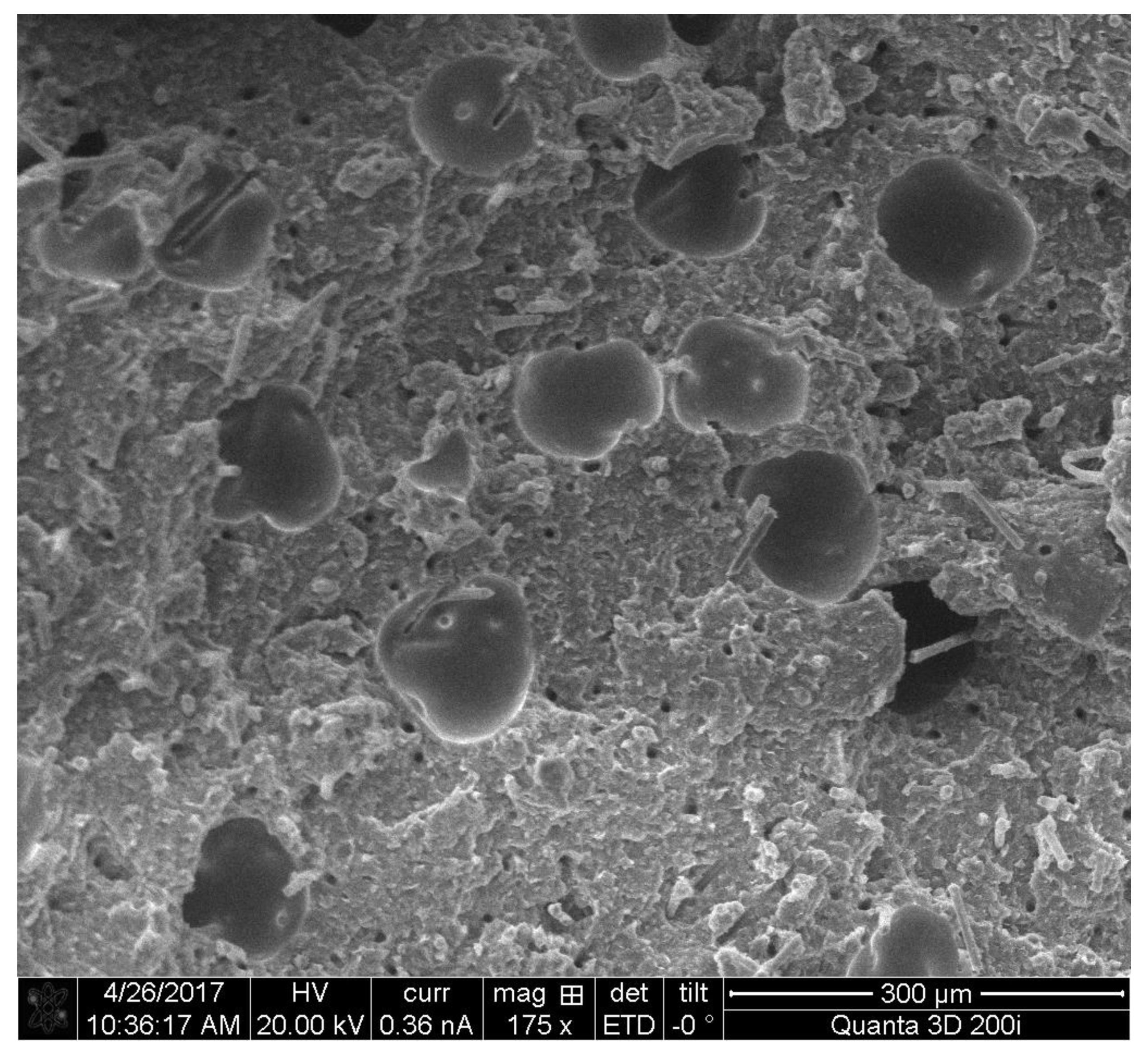
Figure 3 shows that the dispersion of the fillers seems to be uniform; there are no visible aggregates of the fillers or separation of fillers.
3.5. Characterization of the Properties of Recycled PETG Filled with EG, CFs, and Their Combination
Because the price of filament is one of the crucial requirements for mass production of 3D printing we tried to replaces commercial virgin PETG with cheaper recycled PETG whose price is ten times lower. The usage of recycled PETG is also an important part of the circular economy that is on the rise for industrial scales. Also, it significantly helps to protect the planet.
The results of the mechanical properties of pure recycled PETG (sample B) and three prepared composite materials from recycled PETG are summarized in Table 13. As can be seen from the table, the values of the E and σY for all prepared materials based on recycled PETG with consideration of the standard deviation, are comparable with the equivalent composites based on virgin PETG, and only the sample BF-5 had a slightly lower σY.
The σB and εB of the prepared recycled PETG composites were comparable with the values for virgin PETG composites. Again, the sample BF-5 had a σB slightly lower than the AF-5 sample. Deterioration of mechanical properties was observed from nanoindentation measurements when all parameters decreased except Er for BF-5 sample. Nevertheless, all mechanical properties were eligible for reinforced PETG filament with regard to the significant reduction of the final price.
The thermal properties are summarized in Table 14. Recycled PETG reached T50 about 5 °C lower than T50 of virgin PETG. The differences between the virgin PETG and recycled PETG composites were not significant after the addition of the filler. This could be caused by the good thermal conductivity of both carbon fillers. The same effect was also observed in case of linear thermal expansion coefficient α, when carbon fillers decreased their values, but the absolute value of recycled PETG composites was slightly higher than the value for virgin PETG composites due to the higher initial value of pure recycled PETG.
The contact angles and densities of the recycled PETG composite materials are recorded in Table 15. Similar to virgin PETG composites, recycled PETG composite with EG had a higher density than the pure polymer sample, and the CF composite had a lower density than the pure polymer matrix. However, the decrease of BF-5 sample density was not as significant as for the AF-5 sample. A completely different situation was observed in the case of the contact angle. In the case of virgin PETG composites, the contact angles decreased after filling with EG or CF, and in the case of recycled PETG these values increased. The growth was not significant; it was only in the range of experimental error.
3.6. Testing of Prepared Samples by 3D Printing
Prepared composite materials were tested with a commercial 3D printer, which uses FFF technology. Materials for testing were prepared as a filament (Figure 4A) and 3D printed spare parts are presented in Figure 4B.
All prepared composite filaments were suitable for 3D printing using the FFF method. The produced filaments had excellent processing properties for 3D printing, except for the AG-10 filaments, which were very brittle and broke during printing. This break was due to overall worse mechanical properties and poor dispersion of filler compared to other EG/PETG composites.
It is necessary to mention the positive effect of partially replacing non-environment friendly CFs for EG—a form of naturally occurring graphite. EG significantly eliminates surface roughness and therefore eliminates a nozzle abrasion, which is a very common problem during 3D printing filaments with CF composites. The most positive effect is reducing the final price of filament when commercial virgin PETG was replaced for cheaper recycled PETG. The final result is a cheaper filament with enhanced mechanical properties which is more suitable from the point of view of ecology.
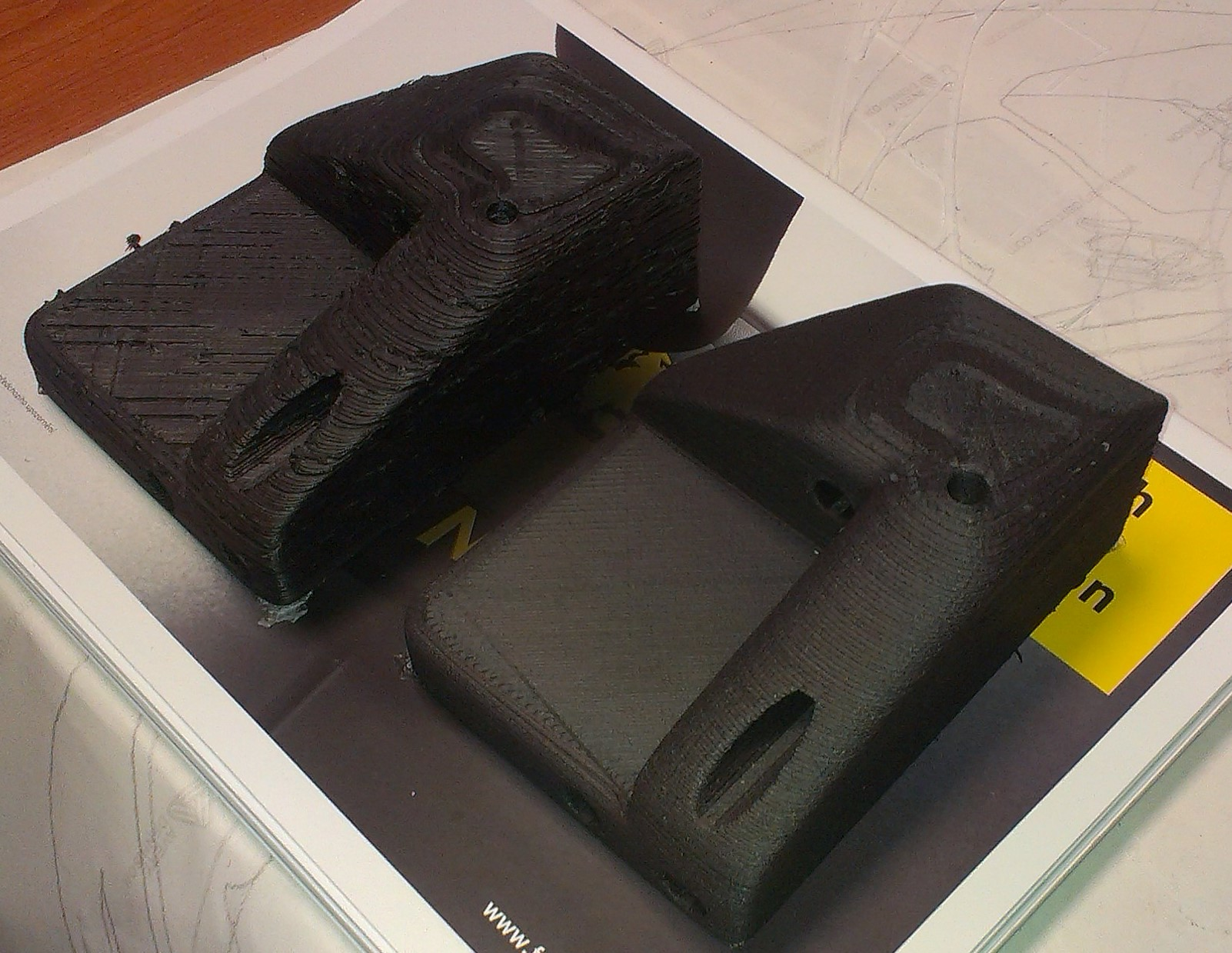
The new hybrid material is very suitable for 3D printing, ranging from small parts (Figure 4B) to larger parts (e.g., large printer pad in Figure 4C) to massive equipment with a total length of over 6 m. The prints are extremely strong, the layers adhere firmly, and the overall strength of the products is extraordinary. The individual layers adhere perfectly. It enables large product printing as well as several-day continuous 3D printing compared to competing materials. The resulting products look more beautiful, which improves subsequent work with products and saves time. As can be seen in Figure 4C, where the products printed under the same conditions are compared, the differences between commercial CF PETG filament (Figure 4C—left) and our hybrid filament from recycled PETG (Figure 4C—right) are clear. Last but not least, the final products are also lighter by about 25%.
4. Conclusions
The paper was devoted to the preparation of polymer composite materials for 3D printing technology by fused filament fabrication. Prepared composite materials were based on virgin PETG and recycled PETG. EG, CFs and their combinations were used as the filler.
From the measured results it is evident that all the composite materials produced have higher values of the E than the pure polymer matrix. Adding EG resulted in enhancement of mechanical properties and increasing density. Composite materials containing CFs and CF/EG also enhanced mechanical properties but decreased density. Addition of the carbon fillers has minimal influence on the thermal properties of the material; however, the presence of CF in composites has a significantly lower thermal expansion coefficient. Replacing virgin PETG with recycled PETG does not significantly change the properties of the filament, just causes a price reduction.
Both PETG and recycled PETG composite materials, except for one sample, have excellent processing properties on a 3D printer with FFF technology. New hybrid filaments bring benefits from an economic point of view (cheaper recycled PETG, lower nozzle wear) as well as from an environmental point of view (recycled materials, partial replacing CF by graphite).
5. Patents
Špitálský, Z.; Kováčová, M.; Ďuriš, V.; Vysopal, M.; Svoboda P. Polymérne kompozity pre 3D tlač (Polymer composites for 3D printing), utility model 8207 Slovakia, 25 July 2018.
Author Contributions
Methodology, M.V.; investigation, J.K. (Jana Kozakovičová), M.P., I.J., I.Č., and J.K. (Jozef Krajčovič); writing—original draft preparation, M.K.; writing—review and editing, M.K.; visualization, M.K.; supervision, Z.Š.; project administration, Z.Š. All authors have read and agreed to the published version of the manuscript.
Funding
The authors are grateful for the financial support of Grant VEGA 2/0051/20.
Conflicts of Interest
The authors declare no conflict of interest.
References
- Hull, C.W. Apparatus for Production of Three-Dimensional Objects by Stereolithography. U.S. Patent No. 4575330, 8 August 1984. [Google Scholar]
- Deckard, C.R.; Beaman, J.J.; Darrah, J.F. Method for Selective Laser Sintering with Layerwise Cross-Scanning. USA Patent No. 5155324, 17 October 1986. [Google Scholar]
- Sun, L.; Hua, G.; Cheng, T.C.E.; Wang, Y. How to price 3D-printed products? Pricing strategy for 3D printing platforms. Int. J. Prod. Econ. 2020. [Google Scholar] [CrossRef]
- Tran, J.L. 3D-Printed Food. Minnesota J. Law Sci. Technol. 2016, 17, 855. [Google Scholar]
- Kanazawa, M.; Inokoshi, M.; Minakuchi, S.; Ohbayashi, N. Trial of a CAD/CAM system for fabricating complete dentures. Dent. Mater. J. 2011, 30, 93–96. [Google Scholar] [CrossRef] [PubMed] [Green Version]
- Van Noort, R. The future of dental devices is digital. Dent. Mater. 2012, 28, 3–12. [Google Scholar] [CrossRef] [PubMed]
- Bazlov, V.A.; Mamuladze, T.Z.; Pavlov, V.V.; Kirilova, I.A.; Sadovoy, M.A. Modern materials in fabrication of scaffolds for bone defect replacement. AIP Conf. Proc. 2016, 1760, 020004. [Google Scholar]
- Mangano, C.; Bianchi, A.; Mangano, F.G.; Dana, J.; Colombo, M.; Solop, I.; Admakin, O. Custom-made 3D printed subperiosteal titanium implants for the prosthetic restoration of the atrophic posterior mandible of elderly patients: A case series. 3D Print. Med. 2020, 6, 1–14. [Google Scholar] [CrossRef] [PubMed] [Green Version]
- Gondokaryono, R.; González, L.; Garrido, K.; Sujumnong, N.; Wee, A.; Goal, A.O. A Graphic User Interface (GUI) to build a cost-effective customizable 3D printed Prosthetic Hand. bioRxiv 2020. [Google Scholar] [CrossRef]
- Mironov, V.; Boland, T.; Trusk, T.; Forgacs, G.; Markwald, R.R. Organ printing: Computer-aided jet-based 3D tissue engineering. Trends Biotechnol. 2003, 21, 157–161. [Google Scholar] [CrossRef]
- Lee Ventola, C. Medical applications for 3D printing: Current and projected uses. Pharm. Ther. 2014, 39, 704–711. [Google Scholar]
- Gonzalez-Gutierrez, J.; Cano, S.; Schuschnigg, S.; Kukla, C.; Sapkota, J.; Holzer, C. Additive manufacturing of metallic and ceramic components by the material extrusion of highly-filled polymers: A review and future perspectives. Materials 2018, 11, 840. [Google Scholar] [CrossRef] [PubMed] [Green Version]
- Paszkiewicz, S.; Szymczyk, A.; Pawlikowska, D.; Irska, I.; Taraghi, I.; Pilawka, R.; Gu, J.; Li, X.; Tu, Y.; Piesowicz, E. Synthesis and characterization of poly(ethylene terephthalate-: Co -1,4-cyclohexanedimethylene terephtlatate)- block -poly(tetramethylene oxide) copolymers. RSC Adv. 2017, 7, 41745–41754. [Google Scholar] [CrossRef] [Green Version]
- Rao, Y.Q.; Greener, J.; Avila-Orta, C.A.; Hsiao, B.S.; Blanton, T.N. The relationship between microstructure and toughness of biaxially oriented semicrystalline polyester films. Polymer 2008, 49, 2507–2514. [Google Scholar] [CrossRef]
- Wang, X.; Liu, W.; Zhou, H.; Liu, B.; Li, H.; Du, Z.; Zhang, C. Study on the effect of dispersion phase morphology on porous structure of poly (lactic acid)/poly (ethylene terephthalate glycol-modified) blending foams. Polymer 2013, 54, 5839–5851. [Google Scholar] [CrossRef]
- Chen, T.; Zhang, J.; You, H. Photodegradation behavior and mechanism of poly(ethylene glycol-co-1,4-cyclohexanedimethanol terephthalate) (PETG) random copolymers: Correlation with copolymer composition. RSC Adv. 2016, 6, 102778–102790. [Google Scholar] [CrossRef]
- Liu, Y. Synthesis and Characterization of Amorphous Cycloaliphatic Copolyesters with Novel Structures and Architectures. Ph.D. Thesis, Virginia Polytechnic Institute and State University, Blacksburg, VA, USA, 22 March 2012. [Google Scholar]
- Li, B.; Zhang, X.; Zhang, Q.; Chen, F.; Fu, Q. Synergistic enhancement in tensile strength and ductility of ABS by using recycled PETG plastic. J. Appl. Polym. Sci. 2009, 113, 1207–1215. [Google Scholar] [CrossRef]
- Scheirs, J.; Long, T.E. (Eds.) Modern Polyesters: Chemistry and Technology of Polyesters and Copolyesters; Wiley Series in Polymer Science; John Wiley & Sons Ltd.: Chichester, UK, 2004; ISBN 0471498564. [Google Scholar]
- Junkar, I.; Vesel, A.; Cvelbar, U.; Mozetič, M.; Strnad, S. Influence of oxygen and nitrogen plasma treatment on polyethylene terephthalate (PET) polymers. Vacuum 2009, 84, 83–85. [Google Scholar] [CrossRef]
- Kepić, D.P.; Ristić, I.S.; Marinović-Cincović, M.T.; Peruško, D.B.; Špitálsky, Z.; Pavlović, V.B.; Budimir, M.D.; Šiffalovič, P.; Dramićanin, M.D.; Mičušík, M.; et al. Simple route for the preparation of graphene/poly(styrene-b-butadiene-b-styrene) nanocomposite films with enhanced electrical conductivity and hydrophobicity. Polym. Int. 2018, 67, 1118–1127. [Google Scholar] [CrossRef]
- Staniszewski, Z.; Fray, M. El Influence of thermally exfoliated graphite on physicochemical, thermal and mechanical properties of copolyester nanocomposites. Polimery 2016, 61, 482–489. [Google Scholar] [CrossRef]
Figure 1.
SEM micrograph of cross-section filament–virgin PETG composite containing 5 wt.% of the expanded graphite.
Figure 1.
SEM micrograph of cross-section filament–virgin PETG composite containing 5 wt.% of the expanded graphite.

Figure 2.
SEM micrograph of the fracture surface of the prepared AF-5 composite material. (A) shows the cross-section of the entire string at 75 magnification, and (B) shows a fracture area at 1228× magnification.
Figure 2.
SEM micrograph of the fracture surface of the prepared AF-5 composite material. (A) shows the cross-section of the entire string at 75 magnification, and (B) shows a fracture area at 1228× magnification.
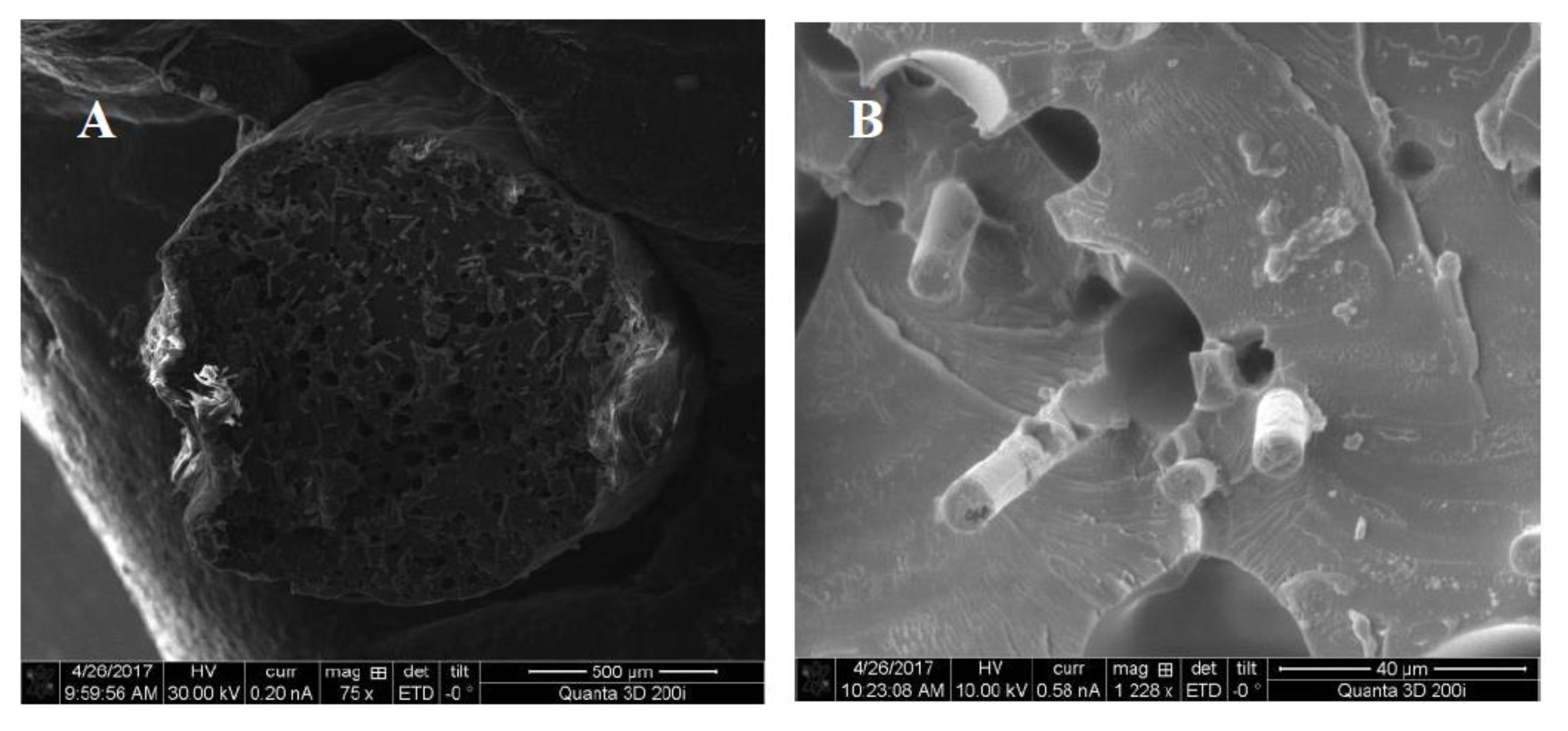
Figure 3.
SEM micrograph of the cross-section is of the hybrid PETG filament containing 5 wt.% of the EG and 5 wt.% of CF. The image was obtained by a scanning electron microscope at a 175× magnification under an electron beam.
Figure 3.
SEM micrograph of the cross-section is of the hybrid PETG filament containing 5 wt.% of the EG and 5 wt.% of CF. The image was obtained by a scanning electron microscope at a 175× magnification under an electron beam.

Figure 4.
(A) Prepared PETG composite filament, (B) 3D printed component, (C) 3D printed large printer pad, left—from commercial CF/PETG filament, right—hybrid filament from recycled PETG.
Figure 4.
(A) Prepared PETG composite filament, (B) 3D printed component, (C) 3D printed large printer pad, left—from commercial CF/PETG filament, right—hybrid filament from recycled PETG.


Table 1.
Overview of prepared virgin PETG composite materials.
| wt.% PETG | wt.% EG | wt.% T700S | wt.% Filler | |
|---|---|---|---|---|
| 100% | 0% | 0% | 0% | |
| AG-1 | 99% | 1% | 0% | 1% |
| AG-2 | 98% | 2% | 0% | 2% |
| AG-3 | 97% | 3% | 0% | 3% |
| AG-4 | 96% | 4% | 0% | 4% |
| AG-5 | 95% | 5% | 0% | 5% |
| AG-10 | 90% | 10% | 0% | 10% |
| AF-1 | 99% | 0% | 1% | 1% |
| AF-2 | 92% | 0% | 2% | 2% |
| AF-3 | 97% | 0% | 3% | 3% |
| AF-4 | 96% | 0% | 4% | 4% |
| AF-5 | 95% | 0% | 5% | 5% |
| AF-10 | 90% | 0% | 10% | 10% |
| AF-20 | 80% | 0% | 20% | 20% |
| AGF-8:2 | 90% | 8% | 2% | 10% |
| AGF-6:4 | 90% | 6% | 4% | 10% |
| AGF-5:5 | 90% | 5% | 5% | 10% |
| AGF-4:6 | 90% | 4% | 6% | 10% |
| AGF-2:8 | 90% | 2% | 8% | 10% |
Table 2.
Overview of prepared recycled PETG composite materials.
| wt.% PETG | wt.% EG | wt.% T700S | wt.% Filler | |
|---|---|---|---|---|
| B | 100% | 0% | 0% | 0% |
| BG-5 | 95% | 5% | 0% | 5% |
| BF-5 | 95% | 0% | 5% | 5% |
| BGF-5:5 | 90% | 5% | 5% | 10% |
Table 3.
Experimental properties of virgin PETG (sample A) and recycled PETG (sample B).
| E (MPa) | σY (MPa) | σB (MPa) | εB (%) | T10 (°C) | T50 (°C) | m550 (%) | Contact Angle (°) | ρ (g·cm−3) | |
|---|---|---|---|---|---|---|---|---|---|
| A | 1600 ± 90 | 58.3 ± 2.1 | 59.7 ± 5.5 | 362.5 ± 10.9 | 402.1 | 431.8 | 9.0 | 86.9 ± 2.6 | 1.27 |
| B | 1690 ± 40 | 58.4 ± 4.6 | 55.1 ± 1.4 | 326.2 ± 52.8 | 401.9 | 426.5 | 9.2 | 83.3 ± 2.6 | 1.32 |
E—Young’s modulus, σY—tensile stress at yield, σB—tensile stress at break, εB—elongation at break, T10—the temperature at which 10% weight loss was recorded, T50—the temperature at which 50% weight loss was recorded, m550—char yield at 550°C, ρ—density.
Table 4.
Mechanical properties of virgin PETG filled with expanded graphite.
| Sample | E (MPa) | σY (MPa) | σB (MPa) | εB (%) | Er (GPa) | H (GPa) |
|---|---|---|---|---|---|---|
| A | 1600 ± 90 | 58.3 ± 2.1 | 59.7 ± 5.5 | 362.5 ± 10.9 | 2.59 ± 0.50 | 0.13 ± 0.03 |
| AG-1 | 1970 ± 120 | 57.7 ± 4.4 | 57.6 ± 4.3 | 4.4 ± 0.4 | 2.80 ± 0.10 | 0.14 ± 0.01 |
| AG-2 | 2040 ± 75 | 55.1 ± 1.9 | 53.5 ± 3.9 | 4.5 ± 0.6 | 2.88 ± 0.36 | 0.13 ± 0.02 |
| AG-3 | 2150 ± 225 | 54.1 ± 3.3 | 53.1 ± 2.3 | 4.4 ± 0.5 | 3.07 ± 0.13 | 0.14 ± 0.01 |
| AG-4 | 2190 ± 40 | 55.4 ± 5.2 | 53.6 ± 6.6 | 4.4 ± 0.8 | 3.07 ± 0.17 | 0.14 ± 0.01 |
| AG-5 | 2250 ± 70 | 54.6 ± 3.9 | 53.4 ± 4.0 | 4.5 ± 0.9 | 3.29 ± 0.17 | 0.14 ± 0.01 |
| AG-10 | 2630 ± 90 | 32.1 ± 2.2 | 32.2 ± 1.8 | 2.4 ± 0.2 | 3.86 ± 0.20 | 0.14 ± 0.01 |
E—Young’s modulus, σY—tensile stress at yield, σB—tensile stress at break, εB—elongation at break, Er—reduced Young’s modulus, H—hardness.
Table 5.
Thermal properties of the prepared composite materials–virgin PETG and expanded graphite.
| Sample | T10 (°C) | T50 (°C) | m550 (%) | α (10−6 K−1) |
|---|---|---|---|---|
| A | 402.1 | 431.8 | 9.0 | 60.12 |
| AG-1 | 401.6 | 426.2 | 9.2 | 60.70 |
| AG-2 | 402.6 | 427.5 | 9.7 | 62.06 |
| AG-3 | 402.1 | 428.5 | 9.2 | 64.85 |
| AG-4 | 403.3 | 430.5 | 10.0 | 52.07 |
| AG-5 | 402.9 | 431.7 | 10.9 | 51.23 |
| AG-10 | 404.3 | 432.5 | 12.4 | 55.14 |
Table 6.
The densities and contact angles of the prepared virgin PETG composite materials with the EG.
Table 6.
The densities and contact angles of the prepared virgin PETG composite materials with the EG.
| Sample | Density (g·cm−3) | Contact Angle (°) |
|---|---|---|
| A | 1.27 | 86.9 ± 2.6 |
| AG-1 | 1.30 | 78.8 ± 3.8 |
| AG-2 | 1.30 | 76.9 ± 3.6 |
| AG-3 | 1.31 | 75.1 ± 2.4 |
| AG-4 | 1.31 | 73.3 ± 4.1 |
| AG-5 | 1.32 | 71.3 ± 3.5 |
| AG-10 | 1.32 | 70.9 ± 5.2 |
Table 7.
Mechanical properties of virgin PETG filled with carbon fibers.
| Sample | E (MPa) | σY (MPa) | σB (MPa) | εB (%) | Er (GPa) | H (GPa) |
|---|---|---|---|---|---|---|
| A | 1600 ± 90 | 58.3 ± 2.1 | 59.7 ± 5.5 | 362.5 ± 10.9 | 2.59 ± 0.50 | 0.13 ± 0.03 |
| AF-1 | 1850 ± 100 | 60.1 ± 1.8 | 66.4 ± 1.8 | 6.2 ± 2.7 | 2.72 ± 0.12 | 0.14 ± 0.0 |
| AF-2 | 1990 ± 135 | 61.2 ± 4.3 | 64.9 ± 5.6 | 5.7 ± 1.2 | 2.69 ± 0.22 | 0.14 ± 0.02 |
| AF-3 | 2110 ± 110 | 65.6 ± 3.0 | 65.0 ± 3.2 | 5.0 ± 0.1 | 2.60 ± 0.18 | 0.15 ± 0.01 |
| AF-4 | 2370 ± 285 | 66.3 ± 2.2 | 66.4 ± 2.1 | 4.8 ± 0.3 | 2.60 ± 0.37 | 0.13 ± 0.02 |
| AF-5 | 2860 ± 190 | 75.3 ± 4.5 | 72.1 ± 1.0 | 5.1 ± 0.5 | 2.72 ± 0.31 | 0.13 ± 0.02 |
| AF-10 | 3430 ± 120 | 75.4 ± 3.4 | 73.5 ± 6.6 | 5.7 ± 1.3 | 2.75 ± 0.53 | 0.13 ± 0.03 |
| AF-20 | 3580 ± 275 | 75.8 ± 1.7 | 74.4 ± 2.1 | 3.9 ± 1.3 | 3.09 ± 0.67 | 0.13 ± 0.04 |
Table 8.
Thermal properties of the prepared composite materials–virgin PETG and CFs.
| Sample | T10 (°C) | T50 (°C) | m550 (%) | α (10−6 K−1) |
|---|---|---|---|---|
| A | 402.1 | 431.8 | 9.0 | 60.12 |
| AF-1 | 397.2 | 425.9 | 7.1 | 55.12 |
| AF-2 | 399.6 | 427.4 | 7.8 | 51.46 |
| AF-3 | 399.3 | 427.3 | 9.5 | 48.16 |
| AF-4 | 399.7 | 427.5 | 9.2 | 45.35 |
| AF-5 | 400.3 | 428.4 | 11.3 | 39.74 |
| AF-10 | 401.0 | 429.6 | 14.8 | 34.35 |
| AF-20 | 401.1 | 432.7 | 23.7 | 28.79 |
Table 9.
The densities and contact angles of the prepared virgin PETG composite materials with the CFs.
Table 9.
The densities and contact angles of the prepared virgin PETG composite materials with the CFs.
| Sample | Density (g·cm−3) | Contact Angle (°) |
|---|---|---|
| A | 1.27 | 86.9 ± 2.6 |
| AF-1 | 1.27 | 77.5 ± 4.9 |
| AF-2 | 1.24 | 76.5 ± 3.5 |
| AF-3 | 1.16 | 77.9 ± 4.4 |
| AF-4 | 1.12 | 75.4 ± 3.3 |
| AF-5 | 1.13 | 74.7 ± 4.3 |
| AF-10 | 1.13 | 70.3 ± 3.0 |
| AF-20 | 1.12 | 64.8 ± 3.6 |
Table 10.
Mechanical properties of virgin PETG filled with EG and CFs.
| Sample | E (MPa) | σY (MPa) | σB (MPa) | εB (%) | Er (GPa) | H (GPa) |
|---|---|---|---|---|---|---|
| A | 1600 ± 90 | 58.3 ± 2.1 | 59.7 ± 5.5 | 362.5 ± 10.9 | 2.59 ± 0.50 | 0.13 ± 0.03 |
| AGF-8:2 | 2646 ± 170 | 63.4 ± 2.7 | 58.6 ± 2.3 | 4.6 ± 0.8 | 4.02 ± 0.24 | 0.16 ± 0.02 |
| AGF-6:4 | 3364 ± 190 | 66.9 ± 5.9 | 65.7 ± 5.8 | 4.2 ± 0.8 | 3.76 ± 0.28 | 0.15 ± 0.01 |
| AGF-5:5 | 3054 ± 235 | 66.2 ± 1.1 | 62.4 ± 5.8 | 4.9 ± 1.6 | 3.26 ± 0.38 | 0.14 ± 0.02 |
| AGF-4:6 | 3095 ± 370 | 66.4 ± 4.1 | 63.9 ± 3.9 | 5.1 ± 1.2 | 3.49 ± 0.21 | 0.14 ± 0.01 |
| AGF-2:8 | 3330 ± 480 | 69.1 ± 7.4 | 66.3 ± 1.3 | 4.5 ± 1.6 | 3.35 ± 0.25 | 0.14 ± 0.01 |
Table 11.
Thermal properties of the prepared composite materials–virgin PETG with EG and CF.
| Sample | T10 (°C) | T50 (°C) | m550 (%) | α (10−6 K−1) |
|---|---|---|---|---|
| A | 402.1 | 431.8 | 9.0 | 60.12 |
| AGF-8:2 | 400.9 | 430.1 | 12.0 | 48.86 |
| AGF-6:4 | 401.5 | 431.7 | 15.6 | 48.68 |
| AGF-5:5 | 402.1 | 431.8 | 14.8 | 34.83 |
| AGF-4:6 | 403.6 | 431.9 | 16.8 | 36.61 |
| AGF-2:8 | 401.7 | 431.7 | 14.9 | 40.37 |
Table 12.
The densities of prepared PETG composites with EG and CFs at the total loading of 10 wt.%.
Table 12.
The densities of prepared PETG composites with EG and CFs at the total loading of 10 wt.%.
| Sample | Density (g·cm−3) | Contact Angle (°) |
|---|---|---|
| A | 1.27 | 86.9 ± 2.6 |
| AGF-8:2 | 1.29 | 89.9 ± 3.6 |
| AGF-6:4 | 1.21 | 85.5 ± 6.7 |
| AGF-5:5 | 1.20 | 81.3 ± 6.8 |
| AGF-4:6 | 1.20 | 80.2 ± 5.4 |
| AGF-2:8 | 1.17 | 79.3 ± 5.5 |
Table 13.
Mechanical properties of recycled PETG composites.
| Sample | E (MPa) | σY (MPa) | σB (MPa) | εB (%) | Er (GPa) | H (GPa) |
|---|---|---|---|---|---|---|
| B | 1690 ± 45 | 58.4 ± 4.6 | 55.1 ± 1.4 | 326.2 ± 52.8 | 2.41 ± 0.13 | 0.11 ± 0.01 |
| BG-5 | 2115 ± 120 | 53.6 ± 1.8 | 52.8 ± 1.4 | 4.8 ± 0.7 | 2.87 ± 0.25 | 0.11 ± 0.01 |
| BF-5 | 2500 ± 265 | 67.4 ± 3.0 | 66.8 ± 2.7 | 4.9 ± 0.6 | 3.14 ± 0.38 | 0.11 ± 0.01 |
| BGF-5:5 | 3110 ± 190 | 64.5 ± 4.3 | 63.2 ± 3.3 | 4.3 ± 0.4 | 2.47 ± 0.3 | 0.11 ± 0.02 |
Table 14.
Results of thermogravimetric analysis of the prepared composite materials based on recycled PETG.
Table 14.
Results of thermogravimetric analysis of the prepared composite materials based on recycled PETG.
| Sample | T10 (°C) | T50 (°C) | m550 (%) | α (10−6 K−1) |
|---|---|---|---|---|
| B | 401.9 | 426.5 | 9.2 | 73.71 |
| BG-5 | 402.1 | 429.5 | 10.1 | 61.24 |
| BF-5 | 398.4 | 426.7 | 9.6 | 48.41 |
| BGF-5:5 | 404.9 | 432.2 | 17.4 | 46.04 |
Table 15.
Contact angles and densities of prepared composite materials base on recycled PETG.
| Sample | Contact Angle (°) | Density (g·cm−3) |
|---|---|---|
| B | 83.3 ± 2.6 | 1.32 |
| BG-5 | 87.8 ± 5.1 | 1.33 |
| BF-5 | 87.5 ± 5.6 | 1.29 |
| BGF-5:5 | 86.8 ± 3.6 | 1.25 |
© 2020 by the authors. Licensee MDPI, Basel, Switzerland. This article is an open access article distributed under the terms and conditions of the Creative Commons Attribution (CC BY) license (http://creativecommons.org/licenses/by/4.0/).
Share and Cite
MDPI and ACS Style
Kováčová, M.; Kozakovičová, J.; Procházka, M.; Janigová, I.; Vysopal, M.; Černičková, I.; Krajčovič, J.; Špitalský, Z. Novel Hybrid PETG Composites for 3D Printing. Appl. Sci. 2020, 10, 3062. https://doi.org/10.3390/app10093062
AMA Style
Kováčová M, Kozakovičová J, Procházka M, Janigová I, Vysopal M, Černičková I, Krajčovič J, Špitalský Z. Novel Hybrid PETG Composites for 3D Printing. Applied Sciences. 2020; 10(9):3062. https://doi.org/10.3390/app10093062
Chicago/Turabian StyleKováčová, Mária, Jana Kozakovičová, Michal Procházka, Ivica Janigová, Marek Vysopal, Ivona Černičková, Jozef Krajčovič, and Zdenko Špitalský. 2020. "Novel Hybrid PETG Composites for 3D Printing" Applied Sciences 10, no. 9: 3062. https://doi.org/10.3390/app10093062
Note that from the first issue of 2016, this journal uses article numbers instead of page numbers. See further details here.