Article

Combined Application of Pipe Roof Pre-SUPPORT and Curtain Grouting Pre-Reinforcement in Closely Spaced Large Span Triple Tunnels

1
Key Laboratory for Urban Underground Engineering of Ministry of Education, Beijing Jiaotong University, Beijing 100044, China
2
China Highway Engineering Consulting Group Company LTD, Beijing 100088, China
*
Author to whom correspondence should be addressed.
Appl. Sci. 2020, 10(9), 3186; https://doi.org/10.3390/app10093186
Submission received: 13 April 2020 / Revised: 29 April 2020 / Accepted: 30 April 2020 / Published: 2 May 2020
(This article belongs to the Section Civil Engineering)

Abstract

:
The platform of the Badaling Great Wall Underground Station consisted of large span triple tunnels. The triple tunnels passed through several major faults. Based on preliminary in situ monitoring, the interaction behavior among triple tunnels was significantly severe, and the original supports failed to meet the safety requirement. Therefore, pipe roof pre-support (PRPS) and curtain grouting pre-reinforcement (CGPR) were used as the pre-construction techniques. By numerical investigation, the pipe diameter, the arrangement angle of PRPS, and the grouting thickness of CGPR were optimized as 108 mm, 150°, and 3 m, respectively. According to numerical results, PRPS predominantly bore loose rock and reduced mean crown settlement (MCS), while CGPR primarily improved the mechanical properties of rock and decreased the pillar plastic ratio (PPR). PRPS and CGPR had complementary advantages in time, space, and mechanical properties. PRPS could timely form a strong arch structure far ahead of the tunnel face, CGPR could effectively restrict the development of plastic zone. They mutually and actively formed a strong permanent ring in front of the tunnel face. After the field application of PRPS and CGPR, the mean surrounding rock pressure reduced by 33.4%, the MCS reduced by 58.7%, and no support damage was observed. The excavation safety was guaranteed.

1. Introduction

For large span tunnels excavated in the weak and broken surrounding ground, excessive deformation and potential damage may take place ahead of the excavation face. Pre-construction techniques have been extensively used to minimize pre-deformation and pre-failure of the rock mass. Pre-construction techniques can be divided into pre-support techniques and pre-reinforcement techniques. The core of pre-support techniques is transferring and bearing the rock load to prevent tunnel collapse, while the core of pre-reinforcement techniques is improving the strength and rigidity of surrounding rock to maintain tunnel stability. In tunnel engineering, the pipe roof and curtain grouting are commonly used as the representative techniques of pre-support and pre-reinforcement, respectively.
Pipe roof pre-support (PRPS) consists of grouted steel pipes with large moment inertia. These pipes are circumferentially inserted from the tunnel face with the pipe diameter of 50–200 mm and the advanced length of 20–50 m. With the great stiffness of the steel pipe, the PRPS system could redistribute the stress state ahead of the tunnel face and eventually decrease the ground settlement [1]. Since its first application in Japan in 1971, the PRPS method has been successfully applied to minimize excavation interference and prevent ground collapse in the weak stratum or crossing projects. Ocak [2] found that PRPS could effectively control the ground settlements caused by metro tunnel excavation in the clayey ground. The PRPS method was approximately three times more efficient than the new Austrian tunneling method (NATM) in controlling surface settlement in the same geological ground. Volkmann et al. [3] compared two pipe roof installation methods, including the cased-drilling method and the predrilling method. By on-site measurement with the horizontal inclinometer, they summarized that the cased-drilling method was preferred in strain sensitive ground owing to its better performance in preventing water saturation and flushing erosion. Rostami et al. [4] concluded that PRPS could significantly improve roof conditions by bearing and transferring the vertical pressure. They also noticed that with the increase of the diameter and amount of PRPS, the ground subsidence was considerably reduced. Schumacher et al. [5] numerically modeled the pipe roof with beam elements, and they found that the bending moments of the pipe roof varied with different pipe diameter and pipe spacing. A design criterion for PRPS was put forward based on the numerical bending moment and the analytical bending stress derived by the flexure formula. Then, they suggested a broken rock mass that the pipe roof should hold up ranged from 1.5 to 3 m. Zhang et al. [1] proposed a double-parameter elastic beam model to analytically investigate the working mechanism of PRPS used in the tunnel entrance. The results showed that the load carried by PRPS greatly increased with the deterioration of the surrounding ground, and the load transferring capacity improved with the stiffness increase of primary lining. Niedbalski et al. [6] underlined that the PRPS was necessarily demanded in the excavation of the Laliki tunnel in the Carpathian flysch. Through field monitoring, they verified the important role of PRPS in preventing rock falling and reducing surface deformation.
Curtain grouting pre-reinforcement (CGPR) is injecting cement-based slurry ahead of the tunnel face with the grouting thickness of 1–10 m and the diffusion distance of 10–25 m. Owing to the filling, permeating, compaction, and splitting effect of the CGPR, the broken rock mass could be reinforced, and the ground permeability could be reduced. The CGPR method has already been widely adopted in dam construction [7,8] and slope stabilization [9,10]. In complex tunneling engineering, the grouting method has also shown a significant effect in ground consolidation [11], settlement compensation [12], shear strength enhancement, and water tightness increment. Ganerød et al. [13] reported the pre-grouting application in two subsea tunnels with fault zones, and they observed that pre-grouting volume considerably varied in different fault-related sub-zones. The injected cement ratio among the fault core, inner damage zone, and outer damage zone was given as 1:2:1. Stille et al. [14] reviewed the grouting project of the Namntall Tunnel, and they found the geologic and hydraulic conditions of rock mass greatly influenced the grouting performance. Then, they suggested a novel method to predict hydrogeological conditions and to optimize the grouting process. Zhang et al. [15] presented a practical curtain grouting case in the highly weathered rock mass of Xiang’an subsea tunnel, the process of double compaction grouting and double fracture grouting were elaborated. And the subsea tunnel safely passed through the fault zones with the ground treatment of CGPR. Moreover, Fang et al. [16] proposed a convergence-confinement model [17] to theoretically study the reinforcing effect of CGPR in a circular tunnel, they found the plastic zone may initiate from the outer boundary of the reinforced zone, the inner boundary of the reinforced zone, or both the outer and the inner boundaries simultaneously. Six different configurations were deduced based on the distribution and extent of the plastic zone(s) and the grouting thickness. Seven critical unconfinement factors were solved to define the possible transition between two consecutive configurations.
Previous studies primarily focused on the independent application of PRPS or CGPR in the single tunnel. However, for the closely spaced tunnels excavated in the fault zone or jointed zone, an independent pre-construction technique may fail to meet the high safety requirements. In some cases, the PRPS and the CGPR should be adopted jointly. Besides, due to the inevitably complicated interaction behavior between neighboring tunnels [18], the effects of pre-construction techniques are more challenging to evaluate.
This paper reports the combined application of PRPS and CGPR in the excavation of large span closely spaced triple tunnels of the Badaling Great Wall Underground Station. In situ data, including surrounding rock pressure and crown settlement, were initially monitored to show the urgent need for pre-constructions. Reasonable design parameters of PRPS and CGPR were determined by numerical optimization. The working mechanism of the PRPS and the CGPR were investigated by comparative analysis. The mutual effects of PRPS and CGPR were evaluated and verified by the numerical analysis and the engineering application. This study may provide a practical reference for other similar tunneling projects.

2. Site Description and Experimental Section Monitoring

2.1. Project Overview

The Badaling Great Wall Underground Station is the largest underground high-speed railway station in the world. This station will serve for the 2022 Beijing Winter Olympics. More information associated with the excavation design and the structural response of this station could be found in the studies by Zhang’s research group [19,20,21,22]. This station consists of the concourse and the platform, and the platform was constructed earlier than the concourse. The platform, with a length of 398 m (from DK67 + 851 to DK68 + 249), is composed of triple tunnels with narrow pillars. The triple tunnels are deeply buried with the overburden depth ranges from 70 to 102 m (Figure 1). The triple tunnels were mainly excavated in moderately–completely weathered monzonite granite. There are several faults (F1, F2, and F3) and a sizeable jointed zone in the tunnel site. The faults are torsion- compression fractures, and the fault zones primarily comprise crushed weak rock. The sizeable jointed zone intersects the tunnel bound ranging from DK67 + 900 to DK68 + 000, and the dip and strike are 86°and 335°, respectively. The surrounding rock mass in the fault zone and the jointed zone is generally broken with 8–10 sets of considerably developed joints, most of them are closed joints without any fillings. Referring to the basic quality classification system (BQ system) in China, the surrounding rock in the fault zone was classified as class V. Table 1 [23] shows the simplified relationship of the rock mass qualities between the BQ system and the widely used quality (Q) system. Besides, the triple tunnels are located in the middle–strong water-rich area, and the normal yield of groundwater is approximately 2400 m3/d.
The triple tunnels are symmetrically distributed (Figure 2), with the Left–Right–Middle excavation sequence. The left and the right tunnels, having the same horseshoe cross-sections, are arrival–departure single-track tunnels, and the excavation span and height are 15.94 and 12.15 m, respectively. The middle tunnel is a double-track tunnel with a 14.38 m excavation span and 12.24 m height. The pillar width is narrowly 6 m (i.e., 0.38 D, D is the excavation span of both left and right tunnels). The triple tunnels were excavated using the drilling and blasting method. Each tunnel was excavated in three parts, including the top heading, bench, and the invert. Thus, there were a total of nine excavation stages.

2.2. Field Monitoring of Experimental Section

In the initial excavation period, the section from DK68 + 249 to DK68 + 200 was selected as the preliminary experimental section to reveal the interaction characteristics of the triple tunnels. In the experimental section, the regular supports, which had been successfully applied in a previous single tunnel excavation, were adopted for the triple tunnels. The primary lining consisted of C30 shotcrete with 300 mm thickness, steel frame with 4213 mm2 cross-sectional area, and rock bolt (radially inserted around tunnel contour) with 4.5 m length. The secondary lining was 400 mm thick reinforced concrete with a 28-day compressive strength of 35 MPa. The 12 mm thick composite waterproofing membrane was sandwiched between the primary and secondary linings.
In the experimental section, the monitoring layout is described in Figure 3. The crown settlement was monitored via the total station with a distance interval of 5 m (Figure 4a). The DK68 + 220 was particularly selected for surrounding rock pressure monitoring. For each tunnel, seven double-membrane pressure cells were fixed at the steel frame and directly against the rock to monitor the surrounding rock pressure (Figure 4b). The pressure cells were installed immediately after the excavation of each part of the tunnel. Therefore, the pressure cells at the knees were installed later than others. The measured pressure data were manually collected by the acquisition instrument with the frequency once per day. Noted that all monitoring instruments were implemented behind the tunnel face, which meant the pre-deformation and the pre-load were not observed.

2.3. Monitoring Results of Experimental Section

During the construction of the experimental section, steel frame distortion, shotcrete crack, small scale tunnel collapse, and primary lining leakage were observed several times (Figure 5).
The development of the surrounding rock pressure at DK68 + 220 is plotted in Figure 6. The final distribution of the surrounding rock pressure is shown in Figure 7. The positive value indicates a compressive force between the primary lining and rock mass. The stable distribution of the crown settlement of triple tunnels in the experimental section is shown in Figure 8.
According to the monitoring data, we noted the following trends:
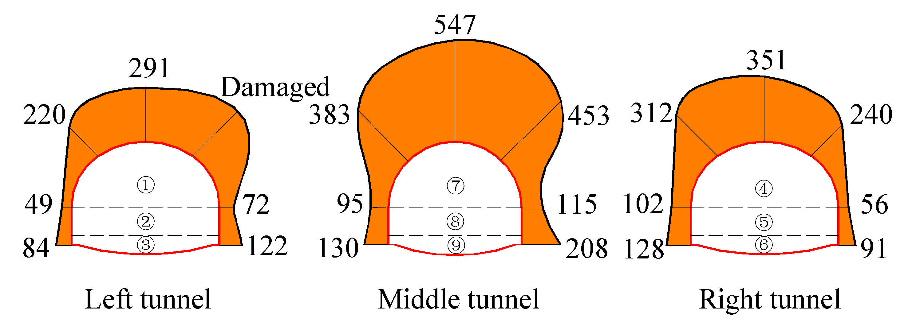
  • For each tunnel, with the stress release of the surrounding ground, the surrounding rock pressure jumped up sharply in the earlier periods. The pressure increments during the top heading excavations primarily accounted for 80% of the final pressure value. It could be inferred that the steel frame and the shotcrete immediately bear rock load after installation.
  • The crown and shoulders were the least favorable parts with considerably larger surrounding rock pressures ranging from 220 to 550 kPa. This trend was also validated by more structural failures, and more small scale tunnel collapses observed at the crown and shoulders.
  • The middle tunnel was found to be the most unfavorable tunnel among the triple tunnels. The mean surrounding rock pressure and the mean crown settlement of the middle tunnel were 275.9 kPa and 60.9 mm, considerably higher than that of the left tunnel (139.7 kPa and 38.8 mm) and the right tunnel (182.9 kPa and 33.6 mm). This behavior might be expressed by that the middle tunnel was excavated in the weak surrounding ground, which had already been severely disturbed by the leading tunnel excavations.
  • Pillar width and excavation sequence greatly influenced the multiple interactions among triple tunnels. Due to the pillar width of 1.65D, the left tunnel was hardly affected by the right tunnel excavation. Conversely, the left tunnel is heavily influenced by the middle tunnel excavation because of the rock pillar of 0.38D. This finding also showed that, with the decrease of pillar width, the rock pillar was more severely worsened and weakened by multiple excavation disturbances.
In conclusion, due to the complex and intense multiple interactions of triple tunnels, the roof conditions of triple tunnels were considerably deteriorated; the rock mass, especially the rock pillar, might be already weakened and damaged ahead of the tunnel face. The original supports could not meet the safety requirement of triple tunnel constructions. Due to the extreme importance of the station and the high durability of station operation, proper pre-construction techniques must be used.

3. Parameter Optimization of PRPS and CGPR

In this project, pipe roof pre-support (PRPS) and curtain grouting pre-reinforcement (CGPR) were jointly used as the pre-construction techniques. A series of numerical analyses were performed by Flac 3D to optimize the design of PRPS and CGPR. The parameter design of the PRPS and the CGPR were carried out separately. The mean crown settlement (MCS, the average crown settlement of the triple tunnels) and the pillar plastic ratio (PPR, the ratio of the plastic zone area to the whole pillar area) were selected as the evaluation parameters. Noted that PRPS and CGPR were used mainly for minimizing the mechanical interactions among triple tunnels and preventing potential mechanical failures. Therefore, we primarily focused on the mechanical responses of triple tunnels. According to the previous cases [8,9,14,15,24], CGPR showed significant performance in improving the impermeability of surrounding rock. During tunneling, although we did not observe sudden water inrush and the seepage effect was considered in rock mass classification through decreasing the mechanical properties of rock, it was better to take hydraulic responses into account in the numerical simulation. We did not quantitatively investigate the hydraulic responses in the simulation, which might be the shortage of this research.

3.1. Numerical Model

The longitudinal length, the width, and the height of this model were 100, 250, and 200 m, respectively (Figure 9). The tunnel lining was simulated as shell elements. The pipe roof and the surrounding rock were modeled using solid elements. The very fine mesh was used to accurately simulate the pipe roof and the neighboring grouting rock mass [25]. This model was initially built in the MIDAS (a finite element analysis software) program, then the mesh information data were input into the FLAC 3D program. The bottom of the model was constrained vertically, whereas four sides were fixed horizontally. The middle section of the model along the longitudinal direction (i.e., y = 50 m) was selected for analysis.
The ratio of horizontal to vertical in situ stress was set to 1.8 by referring to the geotechnical report. According to real circumstance, the excavation sequence in the numerical simulation was Left–Right–Middle, each tunnel was divided into three parts, each excavation circle was 2 m, and the tunnel lining was installed immediately after excavation. The top heading face was 10 m ahead of the bench face, and the invert face was 10 m behind the bench face. The lagging distance between the left tunnel and right tunnel was set to 30 m, which was the same as that between the right tunnel and the middle tunnel. The advanced lengths of the PRPS and the CGPR were set to 40 m and 15 m, respectively.
The mechanical behavior of the surrounding rock was simulated with the Mohr–Coulomb failure criterion. The reinforcement effect of CGPR was simulated by increasing the mechanical parameters of the rock mass in the reinforced zone. The physical and mechanical properties of each material are listed in Table 2.

3.2. Parameter Optimization of PRPS

3.2.1. Pipe Diameter Optimization

The pipe roof consisted of the outer steel pipe and inner grouted concrete, the outer diameter of the steel pipe was D, and the steel pipe thickness was T (Figure 10). The density and the elastic modulus of the steel pipe were 7850 kg/m3 and 210 GPa, respectively, with those of the inner grouting material being 2300 kg/m3 and 25 GPa, respectively. Note that the surrounding rock was also reinforced by grouting, and the elastic modulus of the reinforced zone was 12 GPa [26]. The diameter of the steel pipes to be selected ranged from 89 to 186 mm.
The mechanical parameters of the pipe roof could be calculated according to the equivalence principle of bending stiffness and mass [27]:
E 0 I 0 = E 1 I 1 + k w E 2 I 2 ,
ρ 0 S 0 = ρ 1 S 1 + ρ 2 S 2 ,
where E 0 , I 0 , ρ 0 , S 0 are the equivalent elastic modulus, the moment of inertia, the equivalent density, and the area of the pipe roof; E 1 , I 1 , ρ 1 , S 1 are the elastic modulus, the moment of inertia, the density, and the area of the grouting concrete; E 2 , I 2 , ρ 2 , S 2 are the elastic modulus, the moment of inertia, the density, and the area of the steel pipe. k w is the reduction factor considering the cracking of the grouting concrete, k w = 0.6 .
The pipe roof parameters of six schemes are shown in Table 3. During the pipe diameter optimization, the arrangement angle of the pipe roof was preset to 180° (“180°” was not the final optimized arrangement angle). The MCS and the PPR with different pipe diameters are shown in Figure 11.
Based on numerical results, we observed that the pipe roof played a more critical role in reducing MCS when compared with that in minimizing PPR. When the pipe diameter increased from 0 to 186 mm, the MCS decreased from the 56.2 to 26.5 mm, while the PPR slightly decreased from 100% to 89.5%. It could be expressed that the role of the pipe roof was mainly to form a strong arch structure above the tunnel and to bear loose rock pressure. In comparison, it had less ability in reinforcing the rock pillar due to the limited arrangement area. Therefore, the MCS should be the major evaluation parameter in the optimization of PRPS.
With the increase of pipe diameter, the pipe roof possessed larger stiffness and showed better performance in controlling crown settlement. When the pipe diameter was larger than 108 mm, the downward trend of the MCS became no longer prominent. Therefore, 108 mm could be selected as the optimized pipe diameter.

3.2.2. Arrangement Angle Optimization

The arrangement area of PRPS is also a critical parameter in the design. Eight sets of numerical simulations with different arrangement angle (i.e., 0°, 60°, 90°, 120°, 150°, 180°, 210°, 240°) were performed to obtain optimal scheme, and the results are shown in Figure 12.
It could be observed that the arrangement angle had a great effect on controlling crown settlement. The MCS decreased by 46.1% when the arrangement angle increased from 0° to 180°; in comparison, the PPR merely reduced by 16.5% during the same period. This phenomenon showed good agreements with pipe diameter optimization. The MCS reduced quickly until the arrangement angle reached 150°. Thus, the arrangement angle could be optimized as 150°.
According to the above parameter optimization of PRPS, the MCS was well controlled with the implementation of PRPS. However, the rock pillar was still broken, and the plastic zone penetrated the rock pillar. Therefore, CGPR should also be applied to improve the mechanical properties of the rock pillar.

3.3. Parameter Optimization of CGPR

The grouting thickness is the major parameter of CGPR design because it is directly related to the development and the distribution of the plastic zone [28]. To obtain optimal grouting thickness, in the design stage, there were ten grouting schemes with different grouting thickness ranging from 0 to 5 m. Due to the importance of the rock pillar, increasing the grouting volume and multiple grouting were particularly used to improve the mechanical properties of the rock pillar [14,15]. The material properties of the grouted rock mass and rock pillar are shown in Table 4. The grouting area was the surrounding rock around the excavation contour. Because of the disturbance of the complex grouting process, the primary lining was delayed with a lag distance of 4 m.
According to the numerical results (Figure 13), we found that the PPR was more sensitive to grouting thickness than the MCS. It could be attributed to the larger reinforced zone and smaller stiffness of CGPR. The primary role of CGPR was improving mechanical properties and self-capacity of surrounding rock and protecting the rock pillar from excavation disturbance. Relatively, the stiffness of the grouted rock was much smaller than the pipe roof, which led to less effect of the CGPR in controlling crown settlement. Therefore, the PPR should be the major evaluation parameter in grouting thickness optimization.
The PPR reduced by 78.1% when the grouting thickness increased from 0 to 5 m. When the grouting thickness was larger than 3 m, this decreasing trend became less noticeable. Moreover, the high cost and long construction period of the CGPR should also be taken into consideration. Thus, the reasonable grouting thickness was determined to be 3 m.

4. Numerical Evaluation and Engineering Application

4.1. Numerical Evaluation of the Combined Use of PRPS and CGPR

To better investigate the combined effect of PRPS and CGPR, two cases, namely, without (Case 1) and with (Case 2) the combined implementation of PRPS and CGPR, were numerically compared. The ground settlements of the two cases are shown in Figure 14. The plastic zone contours before and after the uses of PRPS and CGPR are provided in Figure 15.
We noted the following mechanical characteristics:
  • In Case 1, three small rock arches were formed above each tunnel. Besides, a large combined rock arch was also formed across the triple tunnels (Figure 14a). This large combined rock arch was generally entered plastic state (Figure 15a). Similar trends have also been analytically studied by Li [29]. This finding implied that the loosen rock mass above each tunnel might be connected due to the multiple excavation interactions.
  • During the left and right tunnel excavations of Case 1, the rock pillar was severely disturbed and lost the ability to bear loosen rock. The stress concentration phenomenon of the rock pillar was prominent, and the plastic zone completely penetrated the rock pillar (Figure 15a). It inevitably worsened the middle tunnel excavation and caused a larger plastic zone around the middle tunnel. The range of the final plastic zone was considerably large, with more than 15 m extended to the deep surrounding rock.
  • With the combined use of PRPS and CGPR (Case 2), the development of the three separated rock arches to the large combined rock arch was effectively restricted (Figure 14 b), the stress state of the rock pillar was greatly improved (Figure 15b). The safety of the tunnel roof was ensured, with a 56.3% reduction of the MCS. The plastic zone development was also significantly constrained. The plastic zone was primarily confined inside the grouting ring, and the PPR sharply decreased to 30.4%.
  • Moreover, the combined application of PRPS and CGPR (Case 2) showed better performance than that of the independent use of them. The MCS decreased to 24.6 mm, considerably smaller than that of the independent application of PRPS (34.1 mm, Figure 12) or CGPR (42.0 mm, Figure 13). The PPR reduced to 30.4%, more effective than that of the independent application of PRPS (96.8%, Figure 12) or CGPR (35.4%, Figure 13). It could be attributed to the synergistic effect between PRPS and CGPR. PRPS had longer advanced length, larger rigidity, faster construction speed, and smaller reinforcement zone, while CGPR had shorter advanced length, smaller rigidity, slower construction speed, and larger reinforcement zone. Owing to the longer advanced length, larger rigidity, and shorter construction period of PRPS, a strong arch structure could be timely formed far ahead of the tunnel face. Therefore, PRPS could effectively bear vertical rock pressure and protect the tunnel crown. Owing to the broader grouting range of CGPR, the CGPR could greatly improve mechanical properties and the self-stability of the surrounding rock. Thus, the development of plastic zone could be effectively restricted by CGPR. Overall, PRPS and CGPR have complementary advantages in time, space, and mechanical properties, they mutually and actively formed a strong permanent ring in front of the tunnel face.

4.2. Engineering Application

The optimized scheme of pre-construction techniques was timely applied in the later triple tunnel excavation. In practical use, the pipe diameter, the arrangement angle, and the pipe length of the PRPS were 108 mm, 140°, and 39 m, respectively . The pipe amount of the left, middle, and right tunnels are 45, 43, and 45, respectively. Due to the urgency of the construction period, the design scheme of CGPR was not entirely adopted. Nevertheless, the grouting design still provided significant reference. The rock pillar and the middle tunnel were finally selected as the key grouting zones because they were the most vulnerable area according to the preliminary design.
For the installation of PRPS, the concrete arch was cast first to provide strong support for the pipe inserting. The steel pipe was installed by the cased-drilling method [3]. The drilling jumbo was used to drill boreholes and insert steel pipe simultaneously. After the drilling process, the front casing pipe remained in place as the permanent support. The steel pipe was grouted with cement-based slurry, and the slurry diffusion radius was not less than 0.6 times the pipe spacing.
For the execution of CGPR, the 1.0 m thick concrete wall was built first, the combination of the forward grouting and the backward grouting was adopted. Sulfoaluminate cement single slurry (water:cement = 0.8:1) was used as the main cement-based slurry, and the cement-sodium silicate binary slurry was used as the auxiliary slurry. The grouting process should be stopped when the grouting pressure achieved final grouting pressure (3–5 MPa) and the grouting speed was lower than 5 L/min.
To practically evaluate the engineering application, DK 67 + 950 was selected as another monitoring section. The distribution of the surrounding rock pressure is shown in Figure 16. The stable crown settlements of triple tunnels range from DK67 + 940 to DK67 + 980 are shown in Figure 17. The comparisons of representative measured data of two cases are listed in Table 5.
It can be observed that the surrounding rock pressure at the crown and shoulders of each tunnel at DK67 + 950 were mainly concentrated between 200–400 kPa. The mean surrounding rock pressure of triple tunnels at DK67 + 950 was 134.8 kPa, 33.4% lower than that (202.5 kPa) at DK68 + 220. The MCS reduced by 58.7% after pre-support and pre-reinforcement (from 44.5 to 18.4 mm). The tunnel supports were in the good working state, no more steel frame distortion or concrete cracking was observed, and the primary lining leakage was also well controlled. It implied that the combined implementation of PRPS and CGPR greatly improved the mechanical state of the rock–support system.

5. Conclusions

Pipe roof pre-support (PRPS) and curtain grouting pre-reinforcement (CGPR) were successfully used in the closely spaced large span triple tunnels of the Badaling Great Wall Underground Station. The following conclusions were obtained:
  • Based on preliminary field monitoring, it indicated that the rock mass ahead of the tunnel face was severely broken due to the severe multiple interactions among triple tunnels, and the current supports could not meet the safety requirements. Therefore, PRPS and CGPR should be applied.
  • A series of numerical simulations were conducted to optimize design parameters. The optimal pipe diameter, arrangement angle of PRPS were determined to be 108 mm and 150°. The grouting thickness of CGPR was optimized as 3 m.
  • According to numerical results, the PRPS showed a better effect in controlling MCS, while the CGPR showed better performance on reducing PPR. It could be attributed to their different working mechanism, the PRPS predominantly bore external load and prevented tunnel collapse, while the CGPR primarily improved the mechanical properties and enhanced the self-stability of the rock mass.
  • PRPS and CGPR had complementary advantages in time, space, and mechanical properties. PRPS could timely form a strong arch structure far ahead of the tunnel face, CGPR could effectively restrict the development of the plastic zone. They mutually and actively formed a strong permanent ring in front of the tunnel face.
  • The combined implementation of PRPS and CGPR were adopted in subsequent tunnel excavation, the mean surrounding rock pressure decreased by 33.4%, the MCS decreased by 58.7%, respectively, and no significant tunnel damages were observed. The triple tunnel excavation was effectively safeguarded.

Author Contributions

Project administration: D.Z.; Conceptualization, R.L. and P.W.; Data curation, R.L. and Q.F.; Formal analysis, R.L. and D.Z.; Investigation, R.L. and A.L.; Methodology, R.L. and D.Z.; Validation, L.C. and P.W.; Writing—Original draft preparation, R.L.; Writing—Review & editing, D.Z. All authors have read and agreed to the published version of the manuscript.

Funding

The authors gratefully acknowledge the financial support by the Fundamental Research Funds for the Central Universities (Grant No. 2020YJS103), the National Natural Science Foundation of China (Grant No. 51738002) and the National Key Research and Development Program of China (Grant No. 2017YFC0805401).

Conflicts of Interest

The authors declare no conflict of interest.

References

  1. Zhang, Z.; Li, H.; Liu, H.; Li, G.; Shi, X. Load transferring mechanism of pipe umbrella support in shallow-buried tunnels. Tunn. Undergr. Space Technol. 2014, 43, 213–221. [Google Scholar] [CrossRef]
  2. Ocak, I. Control of surface settlements with umbrella arch method in second stage excavations of Istanbul Metro. Tunn. Undergr. Space Technol. 2008, 23, 674–681. [Google Scholar] [CrossRef]
  3. Volkmann, G.M.; Schubert, W. Advantages and specifications for pipe umbrella support systems. In Proceedings of the 14th Australasian Tunnelling Conference, Auckland, New Zealand, 8–10 March 2011. [Google Scholar]
  4. Rostami, A.; Dehkordi, P.K.; Ziarati, M.A.; Jahani, S.; Lotfi, K. The types of tunnels maintenance in umbrella arch method. Open J. Civ. Eng. 2016, 06, 156–162. [Google Scholar] [CrossRef] [Green Version]
  5. Schumacher, F.P.; Kim, E. Modeling the pipe umbrella roof support system in a Western US underground coal mine. Int. J. Rock Mech. Min. Sci. 2013, 60, 114–124. [Google Scholar] [CrossRef]
  6. Niedbalski, Z.; Małkowski, P.; Majcherczyk, T. Application of the NATM method in the road tunneling works in difficult geological conditions—The Carpathian flysch. Tunn. Undergr. Space Technol. 2018, 74, 41–59. [Google Scholar] [CrossRef]
  7. Sadeghiyeh, S.M.; Hashemi, M.; Ajalloeian, R. Comparison of permeability and groutability of Ostur Dam site rock mass for grout curtain design. Rock Mech. Rock Eng. 2013, 46, 341–357. [Google Scholar] [CrossRef]
  8. Rostami Barani, H.R.; Khatib, M.M. Back analysis of grout treatment at Sumbar Dam using the joint hydraulic factor. Rock Mech. Rock Eng. 2015, 48, 2485–2488. [Google Scholar] [CrossRef]
  9. Davis, G.M.; Horswill, P. Groundwater control and stability in an excavation in Magnesian Limestone near Sunderland, NE England. Eng. Geol. 2002, 66, 1–18. [Google Scholar] [CrossRef]
  10. Tiwari, G.; Latha, G.M. Stability analysis and design of stabilization measures for Chenab railway bridge rock slopes. Bull. Eng. Geol. Environ. 2020, 79, 603–627. [Google Scholar] [CrossRef]
  11. Fang, Q.; Zhang, D.; Wong, L.N.Y. Shallow tunnelling method (STM) for subway station construction in soft ground. Tunn. Undergr. Space Technol. 2012, 29, 10–30. [Google Scholar] [CrossRef]
  12. Cao, L.; Zhang, D.; Fang, Q.; Yu, L. Movements of ground and existing structures induced by slurry pressure-balance tunnel boring machine (SPB TBM) tunnelling in clay. Tunn. Undergr. Space Technol. 2020, 97, 103278. [Google Scholar] [CrossRef]
  13. Ganerød, G.V.; Braathen, A.; Willemoes-Wissing, B. Predictive permeability model of extensional faults in crystalline and metamorphic rocks; verification by pre-grouting in two sub-sea tunnels, Norway. J. Struct. Geol. 2008, 30, 993–1004. [Google Scholar] [CrossRef]
  14. Stille, B.; Gustafson, G. A review of the Namntall Tunnel project with regard to grouting performance. Tunn. Undergr. Space Technol. 2010, 25, 346–356. [Google Scholar] [CrossRef]
  15. Zhang, D.; Fang, Q.; Lou, H. Grouting techniques for the unfavorable geological conditions of Xiang’an subsea tunnel in China. J. Rock Mech. Geotech. Eng. 2014, 6, 438–446. [Google Scholar] [CrossRef]
  16. Fang, Q.; Zhang, D.; Zhou, P.; Wong, L.N.Y. Ground reaction curves for deep circular tunnels considering the effect of ground reinforcement. Int. J. Rock Mech. Min. 2013, 60, 401–412. [Google Scholar] [CrossRef]
  17. Peila, D.; Oreste, P. Axisymmetric analysis of ground reinforcing in tunnelling design. Comput. Geotech. 1995, 17, 253–274. [Google Scholar] [CrossRef]
  18. Fang, Q.; Zhang, D.; Li, Q.; Wong, L.N.Y. Effects of twin tunnels construction beneath existing shield-driven twin tunnels. Tunn. Undergr. Space Technol. 2015, 45, 128–137. [Google Scholar] [CrossRef]
  19. Li, A.; Fang, Q.; Zhang, D.; Luo, J.; Hong, X. Blast vibration of a large-span high-speed railway tunnel based on microseismic monitoring. Smart Struct. Syst. 2018, 21, 561–569. [Google Scholar]
  20. Li, A.; Zhang, D.; Fang, Q.; Luo, J.; Cao, L.; Sun, Z. Safety distance of shotcrete subjected to blasting vibration in large-span high-speed railway tunnels. Shock Vib. 2019, 2019, 2429713. [Google Scholar] [CrossRef] [Green Version]
  21. Li, R.; Zhang, D.; Fang, Q.; Li, A.; Hong, X.; Ma, X. Geotechnical monitoring and safety assessment of large-span triple tunnels using drilling and blasting method. J. Vibroeng. 2019, 21, 1373–1387. [Google Scholar]
  22. Liu, D.; Zhang, D.; Fang, Q.; Sun, Z.; Cao, L.; Li, A. Displacement characteristics of shallow-buried large-section loess tunnel with different types of pre-supports: A case study of New Badaling Tunnel. Appl. Sci. 2020, 10, 195. [Google Scholar] [CrossRef] [Green Version]
  23. Zhang, D.; Fang, Q.; Hou, Y.; Li, P.; Yuen Wong, L.N. Protection of buildings against damages as a result of adjacent large-span tunneling in shallowly buried soft ground. J. Geotech. Geoenvironment 2013, 139, 903–913. [Google Scholar] [CrossRef]
  24. Shi, P.; Zhang, D.; Pan, J.; Liu, W. Geological Investigation and Tunnel Excavation Aspects of the Weakness Zones of Xiang’an Subsea Tunnels in China. Rock Mech. Rock Eng. 2016, 49, 4853–4867. [Google Scholar] [CrossRef]
  25. Franzius, J.N.; Potts, D.M. Influence of mesh geometry on three-dimensional finite-element analysis of tunnel excavation. Int J. Geomech. 2005, 5, 256–266. [Google Scholar] [CrossRef]
  26. Shi, Y.; Fu, J.; Yang, J.; Xu, C.; Geng, A.D. Performance evaluation of long pipe roof for tunneling below existing highway based on field tests and numerical analysis: Case study. Int J. Geomech. 2017, 17. [Google Scholar] [CrossRef]
  27. Shi, Y. Study on Mechanical and Engineering Application of Advanced Support for Lower Overburden Tunnel in Weak Stratum. Ph.D. Thesis, Central South University, Changsha, China, 2014. [Google Scholar]
  28. Sun, Z.; Zhang, D.; Fang, Q. Determination method of reasonable reinforcement parameters for subsea tunnels considering ground reinforcement and seepage effect. Appl. Sci. 2019, 9, 3607. [Google Scholar] [CrossRef] [Green Version]
  29. Li, P.; Wang, F.; Fan, L.; Wang, H.; Ma, G. Analytical scrutiny of loosening pressure on deep twin-tunnels in rock formations. Tunn. Undergr. Space Technol. 2019, 83, 373–380. [Google Scholar] [CrossRef]
Figure 1. Geological profile of triple tunnels.
Applsci 10 03186 g001
Figure 2. Excavation sequence and geometry layout of triple tunnels (Unit: m).
Applsci 10 03186 g002
Figure 3. Layout of monitoring points for each tunnel (monitoring instruments at the knees were installed later).
Applsci 10 03186 g003
Figure 4. Installation of monitoring instrument: (a) Total station; (b) Double-membrane pressure cell.
Applsci 10 03186 g004
Figure 5. Tunnel damages in the experimental section: (a) Steel frame distortion; (b) Shotcrete crack; (c) Small scale tunnel collapse; (d) Primary lining leakage.
Applsci 10 03186 g005
Figure 6. Development of surrounding rock pressure at section DK68 + 220: (a) Left tunnel; (b) Right tunnel; (c) Middle tunnel.
Applsci 10 03186 g006
Figure 7. Distribution of surrounding rock pressure at section DK68 + 220 (Unit: kPa).
Applsci 10 03186 g007
Figure 8. Crown settlements of triple tunnels in the experimental section.
Applsci 10 03186 g008
Figure 9. Three-dimensional finite element model of triple tunnels.
Applsci 10 03186 g009
Figure 10. Arrangement sketch of pipe roof pre-support (PRPS).
Applsci 10 03186 g010
Figure 11. Effect of pipe diameter on mean crown settlement (MCS) and pillar plastic ratio (PPR, red elements represent plastic zone).
Applsci 10 03186 g011
Figure 12. Effect of pipe arrangement angle on MCS and PPR.
Applsci 10 03186 g012
Figure 13. Effect of grouting thickness of curtain grouting pre-reinforcement (CGPR) on MCS and PPR.
Applsci 10 03186 g013
Figure 14. Ground settlement of triple tunnels: (a) without PRPS or CGPR (Case 1); (b) with PRPS and CGPR (Case 2).
Applsci 10 03186 g014
Figure 15. Development of plastic zone (red elements) around triple tunnels: (a) without PRPS or CGPR (Case 1); (b) with PRPS and CGPR (Case 2).
Applsci 10 03186 g015
Figure 16. Distribution of surrounding rock pressure at section DK67 + 950 (Unit: kPa).
Applsci 10 03186 g016
Figure 17. Crown settlements of triple tunnels with PRPS and CGPR.
Applsci 10 03186 g017
Table 1. Relationship between the basic quality classification system (BQ system) and the quality system (Q system).
ValueCLASS I (Very Good)CLASS II (Good)CLASS III (Fair)CLASS IV (Poor)CLASS V (Very Poor)
BQ>550451–550351–450251–350<250
Q>4010–404–101–4<1
Table 2. Material properties in the numerical simulation.
Material ρ (kg/m3) E (GPa) ν c (kPa) φ (°) H (m)
Miscellaneous soil filling17500.10.4220205.0
Completely weathered monzonite granite18601.00.401002425.0
Highly weathered monzonite granite20001.50.3716025170.0
Tunnel lining240026.40.20--0.4
Table 3. Cross-section parameters of the pipe roof.
Scheme ID D (mm) T (mm) S 0   ( m 2 ) I 0   ( m 4 ) E 0   ( GPa ) ρ 0   ( kg / m 3 ) Sketch
18946.2 × 10−33.1 × 10−656.73253 Applsci 10 03186 i001
210869.2 × 10−36.7 × 10−662.93465
312781.3 × 10−21.3 × 10−567.13610
4159102.0 × 10−23.1 × 10−567.03608
5178102.5 × 10−24.9 × 10−563.33477
6186102.7 × 10−25.9 × 10−561.93429
Table 4. Material properties of grouted rock mass and rock pillar.
Material ρ (kg/m3) E (GPa) ν c (kPa) φ (°)
Grouted rock mass22002.50.3330030
Grouted rock pillar22008.00.2890042
Table 5. Monitoring data comparison of two cases.
CasesMax Surrounding Rock Pressure (kPa)Mean Surrounding Rock Pressure (kPa)Max Crown Settlement (mm)Mean Crown Settlement (mm)
Case 1547202.576.644.5
Case 2403134.828.718.4
Reduction rate26.3%33.4%62.5%58.7%

