Design and Fabrication of a Novel Window-Type Convection Device

Department of Mechanical Engineering, National United University, Miaoli 36003, Taiwan
*
Author to whom correspondence should be addressed.
Appl. Sci. 2021, 11(1), 267; https://doi.org/10.3390/app11010267
Submission received: 27 November 2020
/
Revised: 23 December 2020
/
Accepted: 26 December 2020
/
Published: 29 December 2020
(This article belongs to the Special Issue Low Carbon Technologies for Sustainable Environment)
Abstract
:Global warming, climate change, and ever-increasing energy demand are among the pressing challenges currently facing humanity. Particularly, indoor air conditioning, a major source of energy consumption, requires immediate improvement to prevent energy crises. In this study, various airfoil profiles were applied to create a window-type convection device that entrains air to improve convection between indoor and outdoor airflows and adjust the indoor temperature. How the geometric structure of the convection device affects its air entrainment performance was investigated on the basis of various airfoil profiles and outlet slit sizes of the airflow multiplier. The airfoil profiles were designed according to the 4-digit series developed by the National Advisory Committee for Aeronautics. The results revealed that airfoil thickness, airfoil camber, and air outlet slit size affected the mass flow rate of the convection device. Overall, the mass flow rate at the outlet of the convection device was more than 10 times greater than at the inlet, demonstrating the potential of the device to improve air convection. To validate these simulated results, the wind-deflector plate was processed using the NACA4424 airfoil with a 1.2 mm slit, and various operating voltages were applied to the convection device to measure the resulting wind speeds and calculate the corresponding mass flow rates. The experimental and simulated results were similar, with a mean error of <7%, indicating that the airfoil-shaped wind-deflector plate substantially improved air entrainment of the convection device to the goal of reduced energy consumption and carbon emissions.
1. Introduction
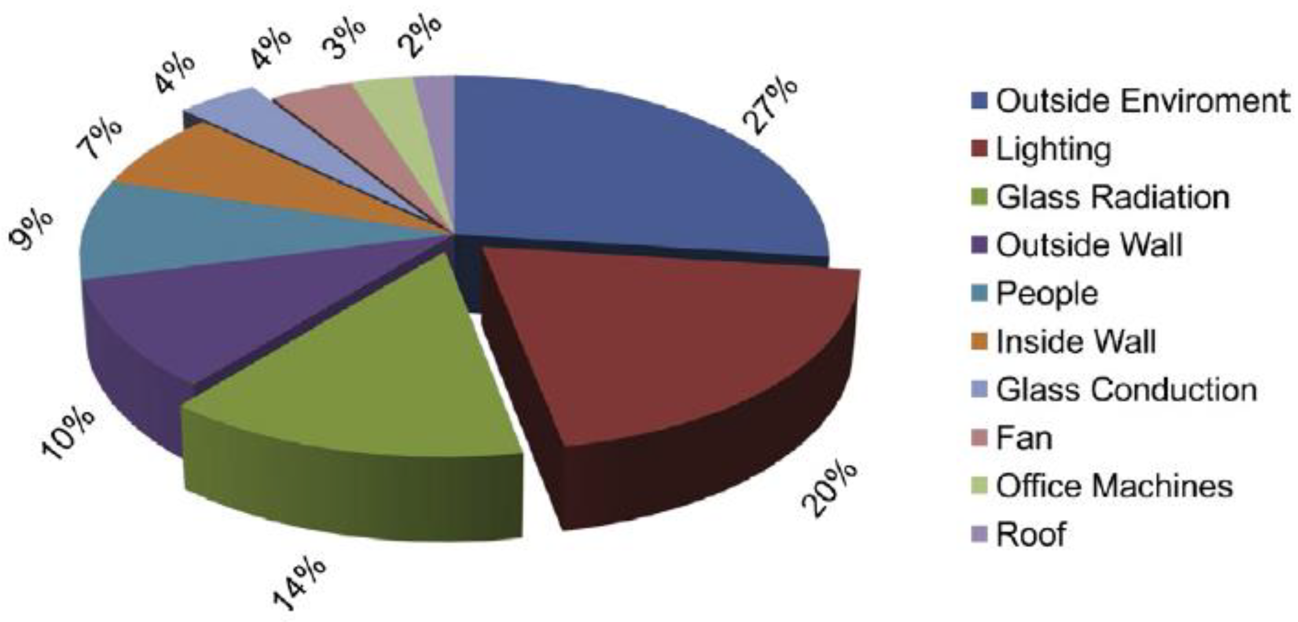
Tackling global warming and climate change, and reducing energy use are currently pressing issues for humanity. In Taiwan, air conditioning (A/C) and lighting account for over 50% of the energy consumed in buildings, of which approximately 39% is used by A/C. Figure 1 depicts the shares of energy consumption by various electrical devices in relation to type of building [1,2], and Figure 2 presents the reasons for indoor A/C use in Taiwan by proportion [2]. For example, “outside environment” comprises 27% of the reasons because sunlight during the day substantially increases the indoor temperature. “Outside wall” is also a main reason for using A/C indoors; thus, even at night, when the outdoor temperature typically decreases to a comfortable level, people tend to adjust the indoor temperature through A/C. To reduce dependence on A/C, cold air from outdoors can be used to adjust the indoor temperature. This facilitates decreasing energy consumption, carbon emissions, and improving sustainable management of Earth’s resources.
To introduce outdoor cold air effectively into buildings for indoor temperature adjustment, a wind-deflector plate was designed with an airfoil profile and installed in windows. The plate acts as a convection device that uses air drag to facilitate air convection inside and outside of a room. Figure 3 illustrates the use of the proposed window-type convection device.
Bladeless fans were designed by Dyson using computational fluid dynamics [3] and, since their advent, numerous studies have been conducted on the design of airflow multipliers. For example, Li et al. [4] found a strong relationship between the curvature radius of the Coanda surface and the blowing performance of a bladeless fan, and they identified the optimal Coanda surface curvature. Lasse and Simon [5] used ANSYS Fluent, a computational fluid dynamics software tool, to study the airflow entrainment and inducement, and air loop amplification, of a Dyson Air Multiplier. Hua et al. [6] used a high-speed camera to observe airflow around the airfoil of a Dyson Air Multiplier, demonstrating that the operation of a bladeless fan depends on its unique airfoil design. Barlow et al. [7] determined that bladeless fans entrain air according to variations in air pressure between different environments; specifically, as compressed air is expulsed from an outlet slit on a bladeless fan, a region of low pressure is momentarily created, which allows relatively high-pressure air from behind the fan to be drawn into the airflow. Thus, the fan uses a small amount of air inflow to generate a substantial amount of air outflow, attaining the goal of airflow amplification. Bladeless fans increase airflow through air entrainment; however, similar to conventional fans, they only enhance the convection of the indoor air and contribute nothing to the adjustment of the indoor temperature. This study, therefore, proposed an airfoil-shaped wind-deflector plate to act as a convection device to improve indoor ventilation.
2. Method and Numerical Computation
A convection device for windows was designed in the shape of an airfoil and analyzed to alleviate the reliance on A/C for temperature adjustment. To determine the effects of the geometric structure of the window-type convection device on its outdoor air entraining performance, ANSYS Fluent was used to compute the flow field of the device. Specifically, the finite volume method was adopted to divide the calculation regions (i.e., the inner flow region of the window-type convection device, the outdoor flow region, and the indoor flow region) into finite control volumes, and the discrete equation for each control volume was estimated in accordance with the principles of mass conservation, momentum conservation, and energy conservation. Given the complexity of the inner runner of the window-type convection device, the following assumptions were proposed to expedite numerical computation without affecting gas dynamics:
- The flow field is steady.
- The flow velocity of the centrifugal fan that propels the window-type convection device is negligibly low; thus, the flow field is assumed to be incompressible.
- Air is defined as a Newtonian fluid with constant density.
- The impact of gravity is neglected.
- The relative velocity between the solid surface and the fluid is zero, satisfying the no-slip condition.
- The roughness of the solid surface is neglected.
2.1. Development of an Analysis Model
Figure 4 depicts the design and structure of the window-type convection device used here. The device comprises an airflow multiplier (composed of a wind-deflector plate and wind-deflector cover) and centrifugal fan, with the bottom of the multiplier attached to the fan (Figure 4a). The multiplier draws air through the rotation of the fan and discharges the air via its outlet slit to entrain outdoor air. Figure 4b presents the runner profile and outlet slit of the airflow multiplier. The present study defined the outlet slit size of the airfoil as the shortest vertical distance between the surfaces of the wind-deflector plate and the wind-deflector cover. In addition, the profile of a wind-deflector plate is based on the 4-digit National Advisory Committee for Aeronautics (NACA) airfoil series, a type of low-speed airfoil with a high lift coefficient and low resistance coefficient, which are extensively applied in the design of airfoil fans [8]. Figure 4c presents the position of the NACA airfoil in the wind-deflector plate, where the cross-section of the NACA airfoil is shown in red. The first NACA airfoil digit denotes the relative camber of the airfoil, or the maximum camber as a percentage of the chord length; the second indicates the distance from the leading edge of the airfoil to the location of the maximum chamber, measured in tenths of the chord length; and the last two represent the relative thickness of the airfoil, or the maximum thickness of the foil as a percentage of the chord length. For example, the NACA 2412 airfoil has a relative camber of 2%, with a maximum camber located 40% (0.4 chords) from the leading edge and a maximum thickness of 12% of the chord length. Figure 5 depicts the profile of the airfoils we discuss in this paper, in which Figure 5a–e presents the profiles of NACA1412, NACA2412, NACA4412, NACA4418, and NACA4424, respectively. NACA1412, NACA2412, and NACA4412 are used to discuss the influence of the relative camber of the airfoil on the mass flow rate and flow velocity, while NACA4412, NACA4418, and NACA4424 are selected to discuss the influence of the relative thickness of the airfoil on the mass flow rate and flow velocity.
Figure 6 presents the analysis model used in this study, which comprised three flow regions: (1) the outdoor flow region (438 mm × 438 mm × 250 mm), (2) the indoor flow region (438 mm × 438 mm × 500 mm), and (3) the inner flow region of the window-type convection device (a runner composed of a wind-deflector plate and wind-deflector cover). The outdoor and indoor flow regions pertain to the neighboring outdoor and indoor environments where the convection device was installed. The geometric dimensions of the inner flow region were specified according to the airfoil structure and the slit size to optimize the performance of the device in entraining outdoor air. During analysis, the relative camber of the airfoil of the wind-deflector plate ranged from 0% to 4%; the maximum camber from the leading edge measured in tenths of the chord length ranged from 0% to 4%; its relative thickness ranged from 8% to 24%; and its outlet slit size ranged from 0.3 to 1.5 mm. The airflow rate and pressure generated by the centrifugal fan were specified on the basis of the boundary condition at the convergence of the airflow multiplier; thus, the structure of the fan was overlooked during the analysis.
2.2. Meshing and Boundary Condition Specifications
After a geometric model for flow-field analysis was established, meshing was applied to the outdoor flow region, indoor flow region, and inner flow region of the window-type convection device, as illustrated in Figure 7. Specifically, panel (a) depicts the overall appearance of the mesh model, panel (b) is a sectional view of the model along its center (cut along the A-A sectional line of Figure 4b), panel (c) is the magnified view of a boxed area in panel (b) (which allows for the determination of the meshing quality of the inner flow region of the window-type convection device), and panel (d) is the magnified view of a boxed area in panel (c) (which allows for observation of the meshing of flow regions around the airfoil and the outlet slit). Because of the highly complex fluid dynamics around the outlet slit, six boundary-layer meshes were applied to the flow region on the airfoil surface to improve computational convergence and reduce computational time. Therefore, the number of meshes and the number of iteration times were effectively reduced in the boundary layer meshes without affecting the precision of the ANSYS Fluent simulation. In addition, a mesh convergence analysis of 5.6 million meshes indicated that convergence occurred in numerical solutions; thus, meshes were established according to this figure.
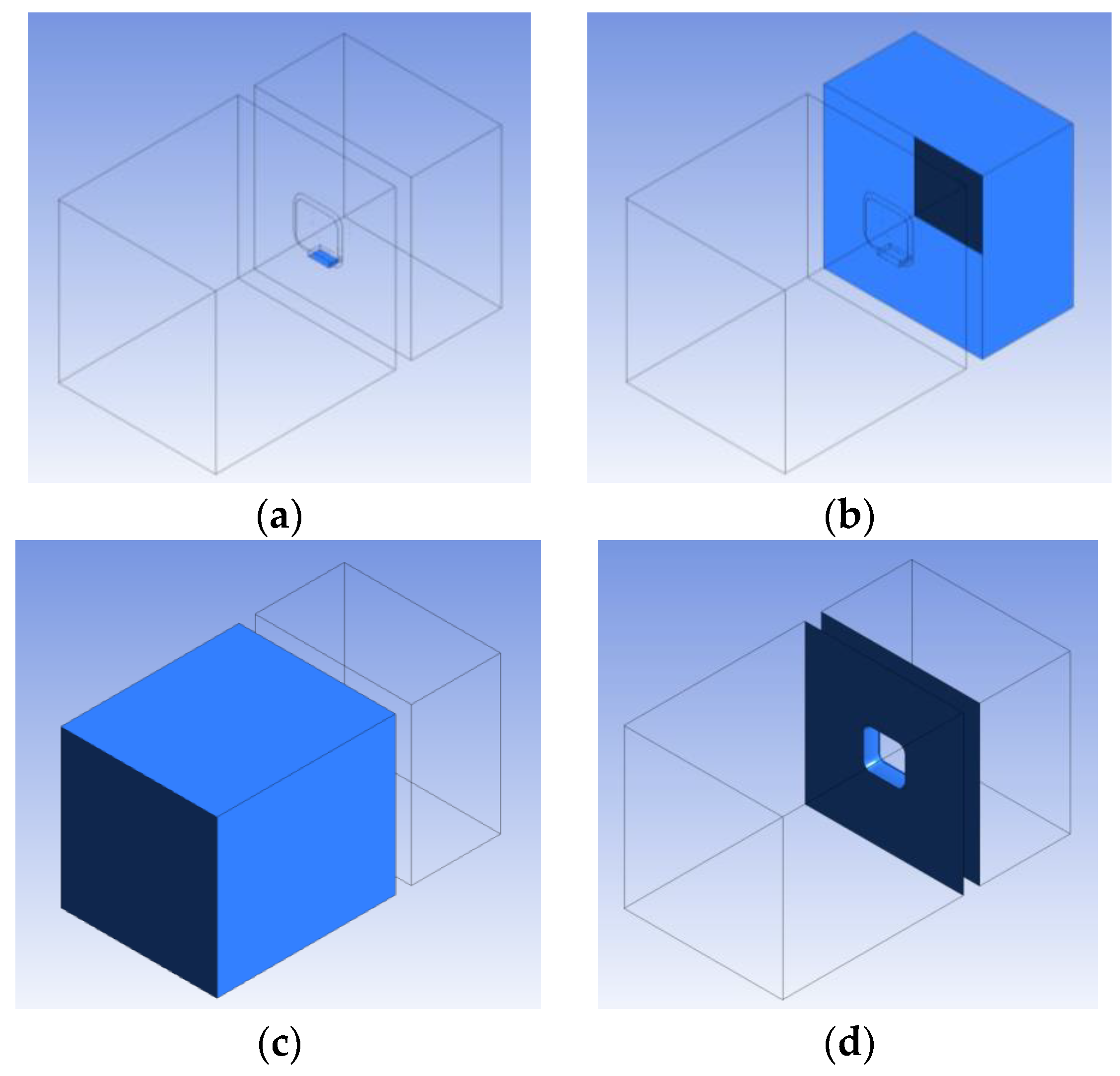
Specifying boundary conditions is critical to flow-field analysis because proper boundary conditions enable more accurate reflection of the actual circumstance(s) of the flow field. In this study, boundary conditions were specified for the runner inlet of the window-type convection device, the inlet and outlet of the flow field, and the wall surface; all of these boundary conditions are highlighted in blue in Figure 8. Specifically, the boundary condition for the runner inlet of the window-type convection device was defined as the amount of airflow and static pressure provided by the centrifugal fan to the airflow multiplier (Figure 8a). The boundary condition for the flow-field inlet was defined as the boundary environmental setting in the outdoor flow region during flow-field analysis (Figure 8b), with pressure at the boundary of the flow-field inlet set at 1 atm to simulate air entrainment by the window-type convection device. The boundary condition for the flow-field outlet was defined as the boundary environmental setting in the indoor flow region (Figure 8c); pressure at the boundary of the flow-field outlet was also set at 1 atm to simulate how the convection device delivered airflow to the boundary of the indoor flow region. In addition, because the window-type convection device was mounted on a wall, the boundary condition for the wall surface of the model was also simulated to satisfy no-penetration and no-slip conditions (Figure 8d).
3. Discussion and Validation of Results
This section discusses the air entrainment performance of the window-type convection device with the airfoil and outlet slit size under various geometric parameterization schemes. The air entrainment performance of the device was determined on the basis of the mass flow rate, flow velocity, and pressure measured on four planes (S, M1, M2, and M3), as depicted in Figure 9. Plane S was the junction between the centrifugal fan and the airflow multiplier, and it was used to estimate the mass flow rate at the convection device inlet. Plane M1 was spaced 1 mm away from the air inlet plane of the convection device, and it was used to estimate the performance of the device in entraining outdoor air. Plane M2 was spaced 1 mm away from the air outlet plane of the device and was used to estimate the total amount of air entrained. Finally, Plane M3 was 438 mm away from the air outlet plane of the device and was used to estimate the overall effects of the device on air convection.
3.1. Effects of Airfoil Camber and Outlet Slit Size on Air Entrainment Performance
The flow velocity distributions generated by the NACA1412, NACA2412, and NACA4412 airfoils with various slit sizes were examined to investigate the effects of the airfoil camber and outlet slit size on the air entrainment performance of the convection device, as shown in Figure 10, which shows the simulation results of flow velocity distributions at the YZ cross-section of the center of the airflow multiplier. In Figure 10, the upper part is the indoor flow region, and the lower part is the outdoor flow region. The flow velocity is presented by color variation. Dark blue is the low-flow velocity, while light blue is the high velocity. In addition, the gray can be regarded as airflow multiplier and wall. Applying a constant slit size and increasing the airfoil camber enabled increasing the distribution of high-velocity airflow around the slit. Thus, increasing the airfoil camber can induce low pressure around the outlet slit, entraining outdoor air through the pressure difference.
The effects of airfoil camber and outlet slit size on air entrainment performance were quantified according to the mass flow rates on Planes S, M1, M2, and M3 observed using the three airfoils. At identical slit sizes, increasing the airfoil camber had a negligible effect on the mass flow rate on Plane S, although the mass flow rate increased notably when the slit was enlarged (Figure 11a). For example, with a slit of 1.5 mm, all airfoils demonstrated a mass flow rate of approximately 0.016 kg/s, which was three times that of the foils with a 0.3 mm slit. Accordingly, the slit size affected the mass flow rate more than the airfoil camber did. Figure 11b illustrates the effects of the airfoil camber on the mass flow rate on Plane M1 of three airfoils at various slit sizes, suggesting that the airfoil camber notably affected the mass flow rate. For example, the NACA4412 at slit sizes of 1.5, 1.2, 0.9, 0.6, and 0.3 mm attained mass flow rates 1.12, 1.09, 1.07, and 1.23 times higher than those of the NACA1412 at equivalent slit sizes, respectively. Thus, increasing the airfoil chamber can increase the mass flow rate on Plane M1, with a peak air entrainment performance at a slit size of 0.6–0.9 mm. Table 1 presents a summary of the airflow velocity and pressure induced on Plane M1 by all of the airfoils at various slit sizes, which determine the air entrainment performance of the convection device. As shown in Table 1, the higher the flow velocity on Plane M1, the lower its corresponding pressure (negative pressure). These corresponding flow pressure changes were due to changes in the velocity of flow passing the slit, indicating that negative pressure around the slit facilitates the convection device to draw more outdoor air.
Figure 11c depicts the mass flow rate at the outlet of Plane M2, which was the sum of those on Planes S and M1, and whose airflow was comprised largely of entrained air. Finally, Figure 11d presents the mass flow rate on Plane M3, which exhibits similar changes to those shown in Figure 11c (namely, decreasing mass flow rate as the airfoil camber decreases); this panel also suggests that the mass flow rate on Plane M3 at a 1.2 mm slit was notably higher than at other slit sizes. Moreover, the mass flow rate on Plane M3 was higher than that on Plane M2, indicating that the convection device also entrained indoor air.
To further elucidate the effects of the thickness, camber, and slit size of the airfoil on the air entrainment performance of the convection device, the airfoil thickness was adjusted from 12% to 18% and 24%. The results revealed mass flow rate changes similar to those presented in Figure 11. Notably, the mass flow rate peaked when the slit size was reduced from 0.8 to 0.6 mm when the airfoil thickness was increased to 24%. Thus, the effects of airfoil thickness and outlet slit size on air entrainment performance necessitate further investigation.
3.2. Effects of Airfoil Thickness and Outlet Slit Size on Air Entrainment Performance
As illustrated in Figure 12a, increasing the airfoil thickness exerted negligible effects on the mass flow rate on Plane S, with a relative camber of 4%, a maximum camber located 40% from the leading edge, an increase in the maximum thickness from 12% to 24%, and a lengthening of the slit size from 0.3 to 1.5 mm. Furthermore, the mass flow rate on Plane S of the NACA4424 airfoil demonstrated less noticeable improvement in relation to the slit size than those of the NACA4412 and NACA4418 airfoils did. Next, Figure 12b depicts the effects of the airfoil thickness on the mass flow rate on Plane M1. The highest mass flow rate on Plane M1 of the NACA4424 airfoil occurred with a slit size of 0.6–0.9 mm; however, increasing the airfoil thickness decreased the volume of the runner, thereby reducing the optimal size of the slit. Figure 12c shows the mass flow rate at the outlet of Plane M2 in relation to the airfoil thickness, which was the approximate sum of the mass flow rate at the inlet of Plane S and that on Plane M1; this finding concurs with that illustrated in Figure 11c. In addition, as the slit size increased, the mass flow rate at the inlet of Plane S rose, whereas that at the outlet of Plane M2 declined (Figure 12a,c), indicating that increasing the slit size impeded air entrainment. Finally, Figure 12d outlines the effects of airfoil thickness on the mass flow rate on Plane M3. Notably, the mass flow rate on Plane M3 was higher than that on Plane M2, suggesting that airflows passing Plane M2 induced indoor air entrainment. This phenomenon coincides with the results shown in Figure 11d. Moreover, analyzing the effects of airfoil thickness on the mass flow rate under the relative camber of 1% to 4% revealed similar mass flow rate changes to those presented in Figure 12.
To examine the effects of the geometric structure of the window-type convection device on its air entrainment performance, the mass flow rates at the outlet of Plane M3 and that at the inlet of Plane S were proportionally calculated to determine the ratio of which the flow rate was magnified. Analysis of a range of geometric parameters revealed that the NACA4424 airfoil with a 1.2 mm outlet slit size attained the optimal magnification ratio of 11.59. Therefore, a convection device was constructed on the basis of this parameter to measure the actual flow rate of the device and validate the aforementioned simulation results. Section 3.3 details this validation process.
3.3. Experimental Validation
The optimized geometric dimensions of the air multiplier were experimentally validated to examine the accuracy of the ANSYS Fluent simulation and the feasibility of the convection device. Figure 13 details the assembly, physical appearance, and mass flow rate measurement for the convection device. Specifically, the device was assembled by combining a wind-deflector plate and wind-deflector cover to form the NACA 4424 airfoil with a 1.2 mm slit; the plate and cover were attached to a centrifugal fan, and the three components were mounted on the center of a device substrate (Figure 13a). Figure 13b illustrates the mass flow rate measurement method for the convection device. Specifically, in accordance with Chinese National Standard 547 regarding flow rate measurement, the convection device was positioned 438 mm ahead of the mass flow rate measurement panel. Wind speed data for 64 equally divided areas of the measurement panel were captured to estimate and sum up the mass flow rate on each of the areas, which determined the ability of the convection device to enhance air convection. Wind speed was measured using an anemometer (LM-81AM, Lutron Electronic Enterprise Co., Ltd., Taipei, Taiwan).
Figure 14 illustrates the measurement of flow fields around the convection device. As shown in Figure 14a, the flow-field direction was measured with smoke blown by the centrifugal fan powered at 12 V; the equivalent simulation results are depicted in Figure 14b. Overall, the flow-field measurement results in Figure 14a,b indicate qualitatively similar changes, confirming the feasibility of the convection device.
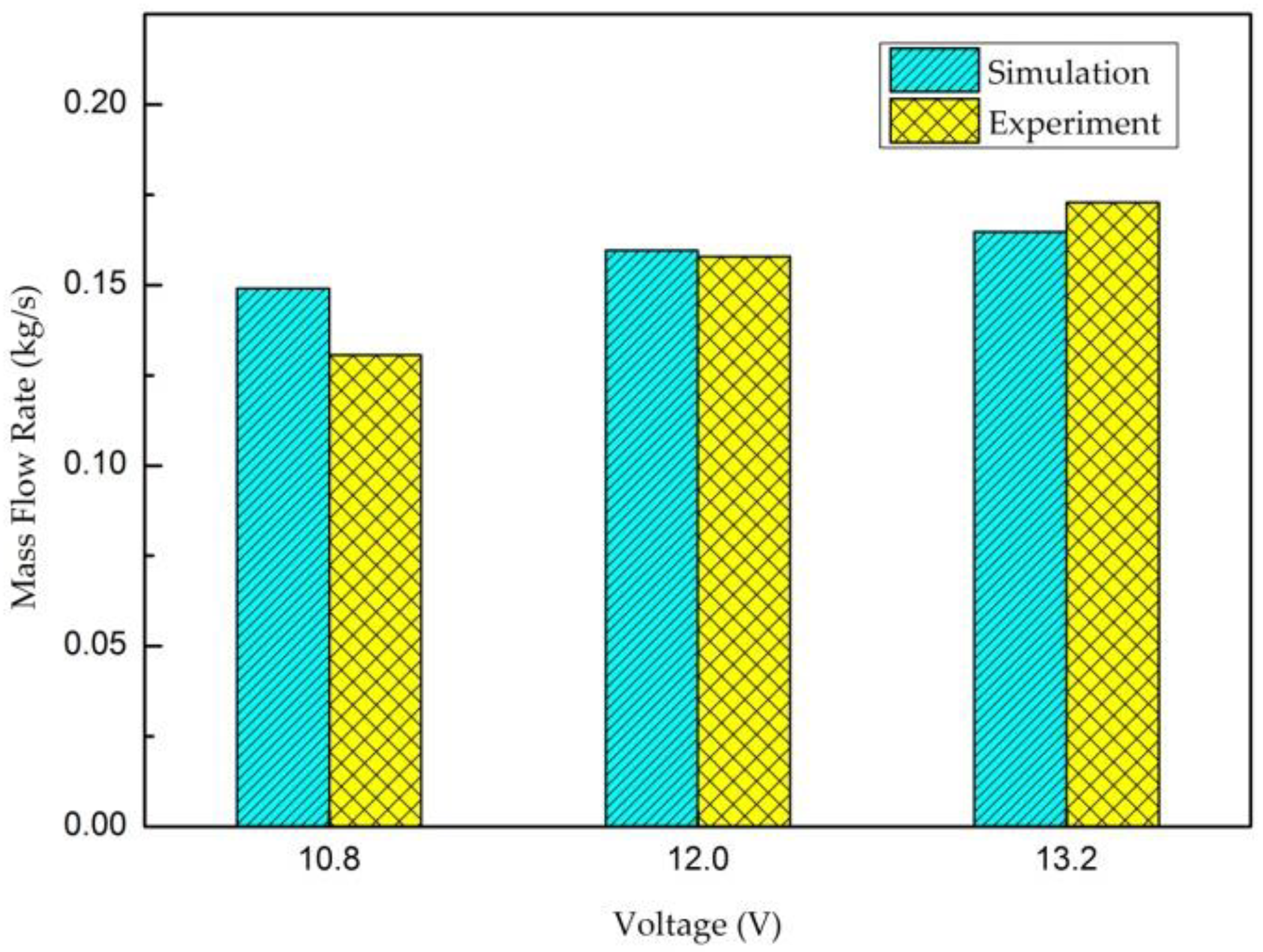
To examine the quantitative differences between the experimental and simulated flow-field measurement results, wind speed data were captured, and the mass flow rates under the experimental and simulated conditions were estimated. Figure 15 shows the mass flow rate under simulated and experimental conditions at three voltages at which the centrifugal fan operated. The mass flow rate under both conditions exhibited similar changes and increased with the operating voltage of the fan. Moreover, the mean error between the simulated and experimental measurements at these varying operating voltages was 6.3%, suggesting that the ANSYS Fluent simulation conducted in this study was highly reliable. This error was attributed to the assumptions of the simulation, the surface roughness of the 3D-printed parts, and the assembly error in the convection device.
4. Conclusions
This paper presented a window-type convection device prepared in accordance with the principles underlying the operation of airflow multipliers. The air entrainment performance of the convection device was optimized by designing its wind-deflector plate in the shape of an airfoil and adjusting the outlet slit size. The analysis results revealed that the mass flow rate of the convection device increased alongside the airfoil camber and thickness. Although decreasing the slit size reduced the flow velocity, it also facilitated improving the entrainment of outdoor air, which is affected by ambient pressure; more specifically, reducing the size of the slit induced lower ambient pressure around it, thereby enhancing the entrainment of outdoor air. Moreover, the mass flow rate at the convection device outlet was 11.6 times that at the inlet, implying that the device has the potential to improve convection between indoor and outdoor airflows, and then to reduce energy consumption and carbon emissions.
The NACA4424 airfoil (namely, 4% relative camber, maximum camber located 40% from the leading edge and maximum thickness of 24% of the chord length) with a 1.2 mm slit, which delivered the highest air entrainment performance during simulation, was applied to conduct an experiment and validate the simulated results. The mean error between the experimental and simulated mass flow rates was 6.3%, suggesting that the ANSYS Fluent simulation was highly accurate, and that the convection device was feasible.
Author Contributions
Conceptualization, Y.-H.G. and W.-H.H.; methodology, Y.-H.G. and W.-H.H.; software, H.-T.L.; validation, H.-T.L., Y.-H.G. and W.-H.H.; formal analysis, H.-T.L. and Y.-H.G.; investigation, H.-T.L., Y.-H.G. and W.-H.H.; resources, Y.-H.G.; data curation, H.-T.L. and W.-H.H.; writing—original draft preparation, W.-H.H.; writing—review and editing, W.-H.H.; visualization, H.-T.L.; supervision, Y.-H.G. and W.-H.H.; project administration, Y.-H.G. and W.-H.H.; funding acquisition, Y.-H.G.; All authors have read and agreed to the published version of the manuscript.
Funding
This research received no external funding.
Institutional Review Board Statement
Not applicable.
Informed Consent Statement
Not applicable.
Data Availability Statement
The data presented in this study are available on request from the corresponding author.
Conflicts of Interest
The authors declare no conflict of interest.
References
- Taiwan Green Productivity Foundation. Energy Audit Annual Report for Non-Productive Industries 2015; Taiwan Green Productivity Foundation: Taipei, Taiwan, 2016; p. 19. [Google Scholar]
- Huang, T.Y.; Hocheng, H.; Chou, T.H.; Yang, W.H.; Ting, C.J.; Cheng, K.Y.; Hsieh, C.W. Design and fabrication of sunlight-redirecting and infrared-insulating microstructure. Energy Build. 2015, 90, 114–126. [Google Scholar] [CrossRef]
- Mason, R.; Pitt, R. Bladeless is more. Ansys Advant. 2010, 4, 5–7. [Google Scholar]
- Li, G.; Hu, Y.; Jin, Y.; Setoguchi, T.; Kim, H.D. Influence of Coanda surface curvature on performance of bladeless fan. J. Therm. Sci. 2014, 23, 422–431. [Google Scholar] [CrossRef]
- Flow Characteristics of the Dyson Air Multiplier. Available online: https://www.scribd.com/document/336690225/cfd (accessed on 28 November 2020).
- Studying Near-Surface Effects of the Dyson Air-Multiplier Airfoil. Available online: https://docplayer.net/22367125-Studying-near-surface-effects-of-the-dyson-air-multiplier-airfoil-team-12-michael-hua-1-dev-ashish-khaitan-2-paul-kintner-1.html (accessed on 28 November 2020).
- Barlow, C.; Lewis, D.; Prior, S.D.; Odedra, S.; Erbil, M.; Karamanoglu, M.; Collins, R. Investigating the use of the Coanda Effect to create novel unmanned aerial vehicles. In Proceedings of the International Conference of Manufacturing and Engineering Systems, Huwei, Taiwan, 17–19 December 2009; pp. 386–391. [Google Scholar]
- Huang, C.H.; Gau, C.W. An optimal design for axial-flow fan blade: Theoretical and experimental studies. J. Mech. Sci. Technol. 2012, 26, 427–436. [Google Scholar] [CrossRef]
Figure 1.
Energy consumption by various electrical devices in relation to type of building [1].
Figure 1.
Energy consumption by various electrical devices in relation to type of building [1].

Figure 2.
Reasons for indoor A/C use in Taiwan [2].
Figure 2.
Reasons for indoor A/C use in Taiwan [2].

Figure 3.
Conceptual design of the proposed window-type convection device.

Figure 4.
(a) Illustration of the window-type convection device, which comprises an airflow multiplier and centrifugal fan; when the centrifugal fan rotates, the airflow multiplier draws air from outside to create an airflow in its runner. (b) Front view and right-side sectional view of the airflow multiplier. (c) Position of the NACA airfoil in the wind-deflector plate.

Figure 5.
Profile of NACA airfoils (a) NACA1412, (b) NACA2412, (c) NACA4412, (d) NACA4418, and (e) NACA4424.
Figure 5.
Profile of NACA airfoils (a) NACA1412, (b) NACA2412, (c) NACA4412, (d) NACA4418, and (e) NACA4424.
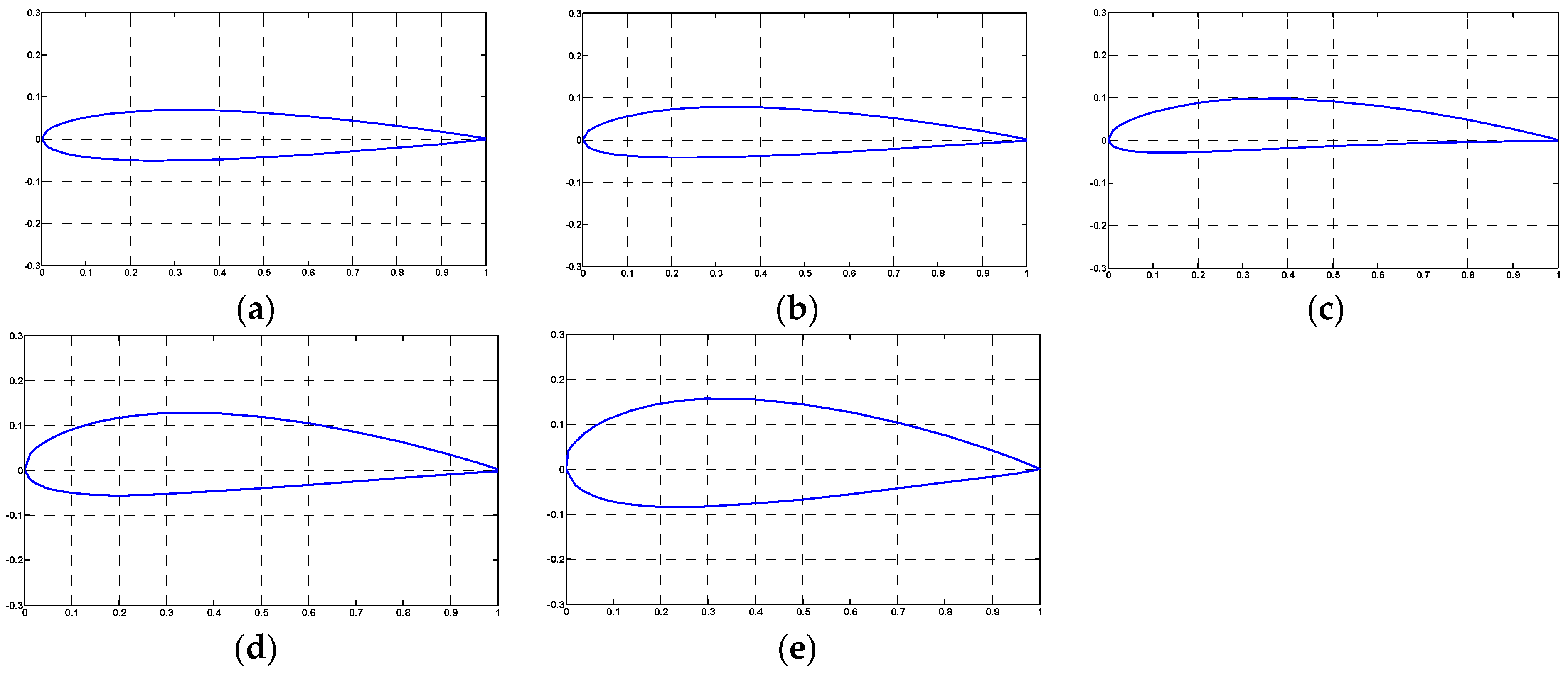
Figure 6.
Geometric model for flow-field analysis, which comprises the outdoor flow region, the indoor flow region, and the inner flow region of the window-type convection device.
Figure 6.
Geometric model for flow-field analysis, which comprises the outdoor flow region, the indoor flow region, and the inner flow region of the window-type convection device.
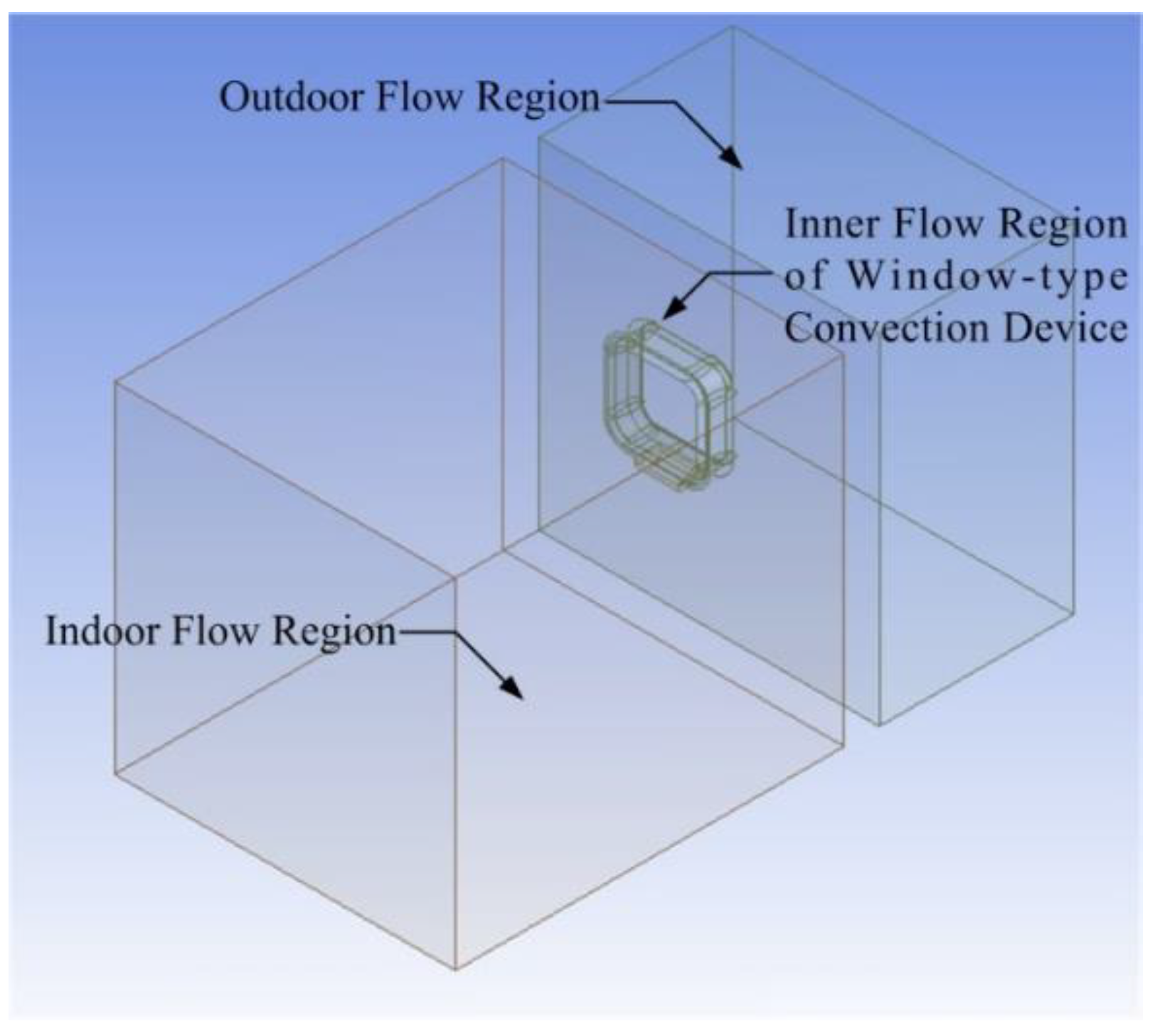
Figure 7.
Meshing results. (a) The overall appearance of the geometric model, (b) the sectional view of the model along its center, (c) the inner flow region of the window-type convection device, and (d) the flow region on the airfoil surface and outlet slit.
Figure 7.
Meshing results. (a) The overall appearance of the geometric model, (b) the sectional view of the model along its center, (c) the inner flow region of the window-type convection device, and (d) the flow region on the airfoil surface and outlet slit.
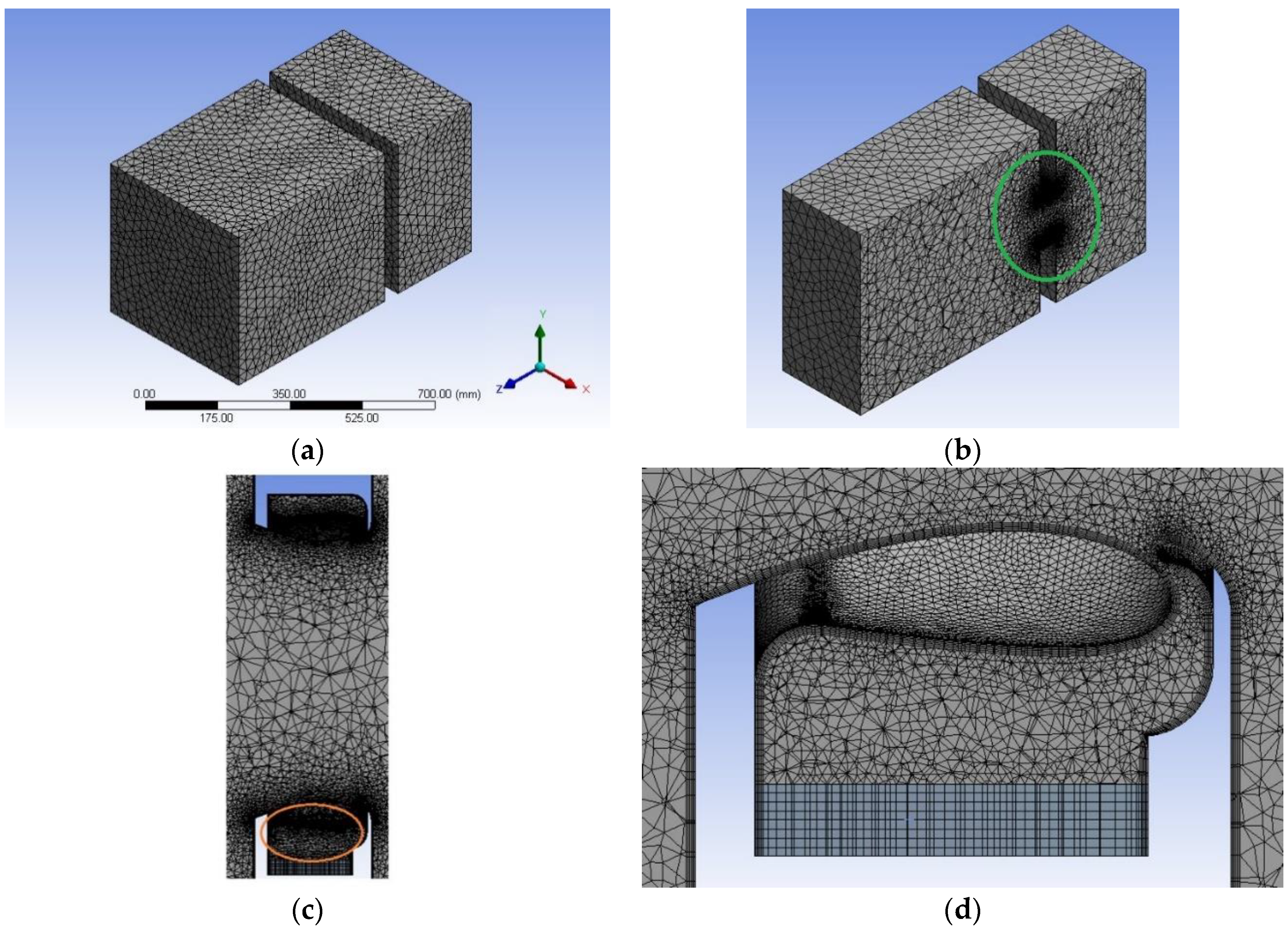
Figure 8.
Areas with boundary conditions (highlighted in blue) in the analysis model. (a) The runner inlet of the window-type convection device, (b) the flow-field inlet, (c) the flow-field outlet, and (d) the wall surface.
Figure 8.
Areas with boundary conditions (highlighted in blue) in the analysis model. (a) The runner inlet of the window-type convection device, (b) the flow-field inlet, (c) the flow-field outlet, and (d) the wall surface.

Figure 9.
Relative positions of numerically measured planes in the analysis model. (a) 3D view, and (b) bottom view.
Figure 9.
Relative positions of numerically measured planes in the analysis model. (a) 3D view, and (b) bottom view.
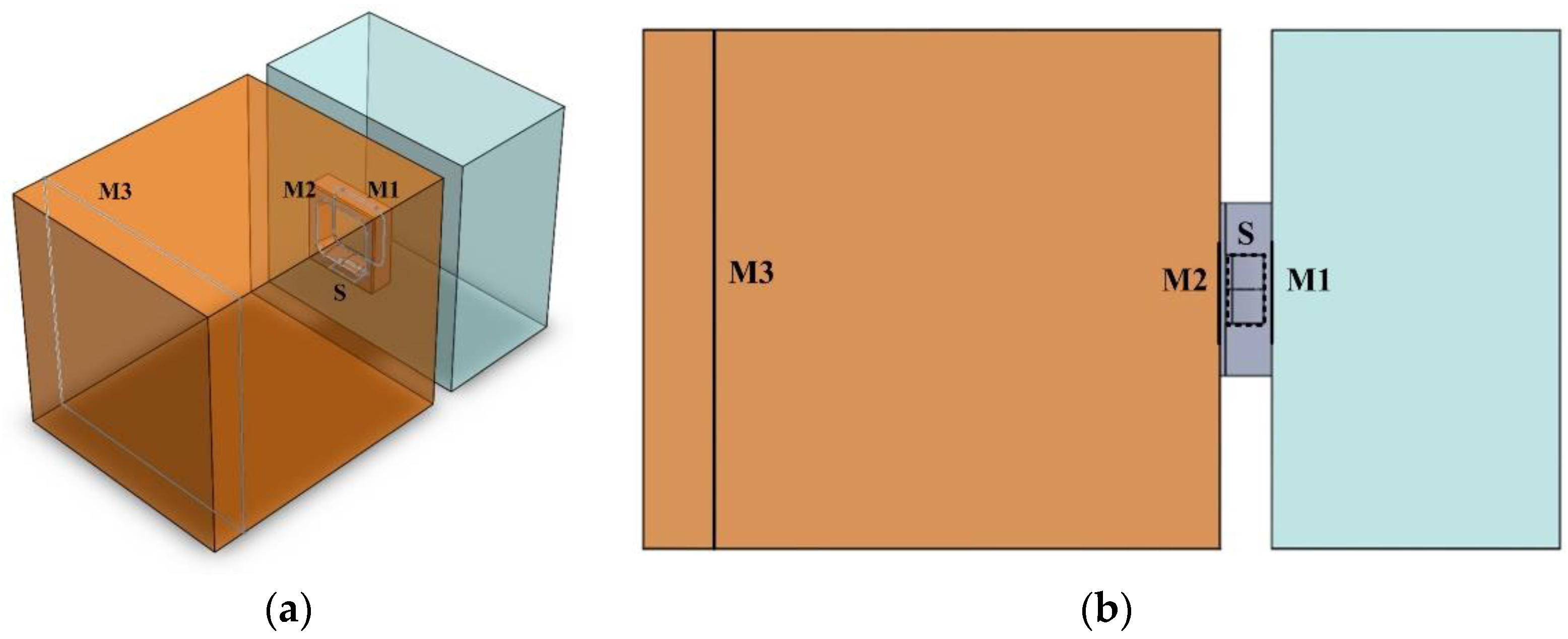
Figure 10.
Flow velocity distributions, with fixed airfoil thickness and various airfoil cambers and outlet slit sizes.
Figure 10.
Flow velocity distributions, with fixed airfoil thickness and various airfoil cambers and outlet slit sizes.
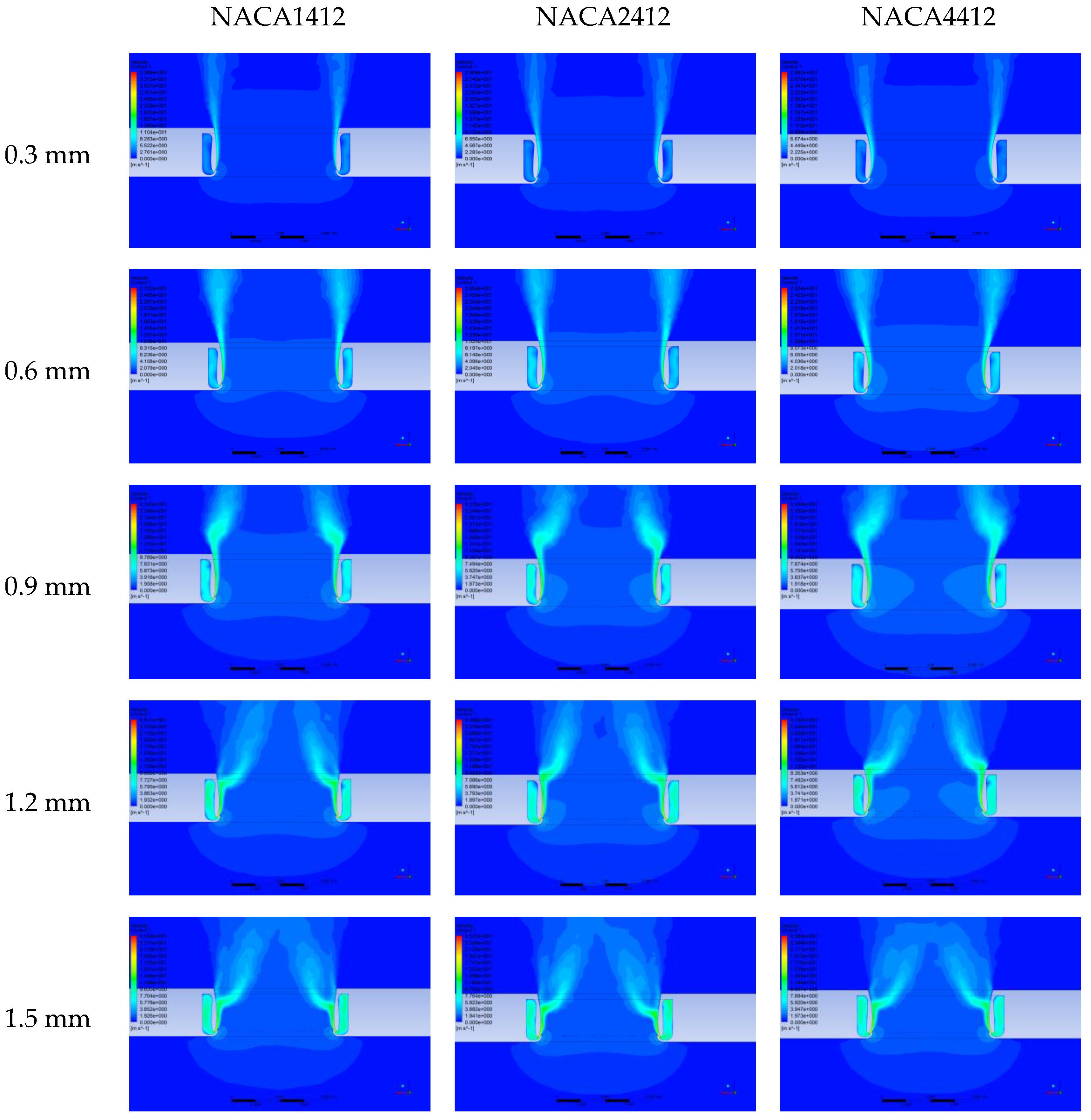
Figure 11.
Mass flow rate (a) at the inlet of Plane S, (b) on Plane M1, (c) at the outlet of Plane M2, and (d) at the outlet of Plane M3 in relation to the slit sizes of the NAC1412, NACA2412, and NACA4412 airfoils.
Figure 11.
Mass flow rate (a) at the inlet of Plane S, (b) on Plane M1, (c) at the outlet of Plane M2, and (d) at the outlet of Plane M3 in relation to the slit sizes of the NAC1412, NACA2412, and NACA4412 airfoils.
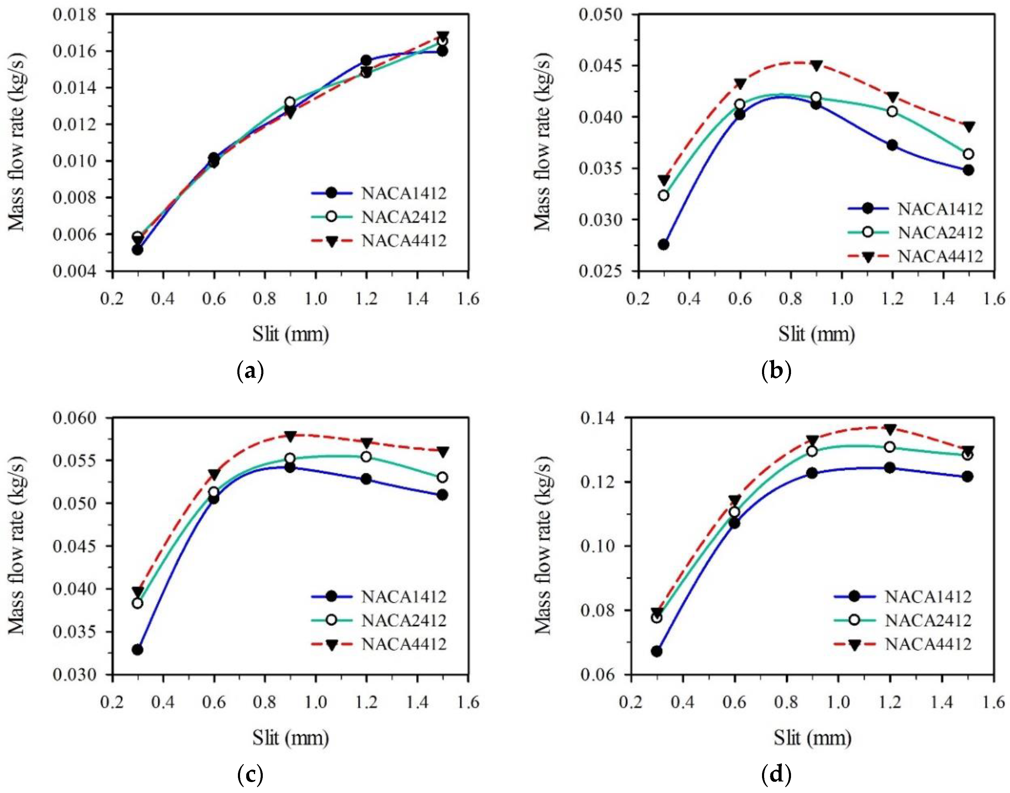
Figure 12.
Mass flow rate (a) at the inlet of Plane S, (b) on Plane M1, (c) at the outlet of Plane M2, and (d) at the outlet of Plane M3 in relation to the slit sizes of the NACA4412, NACA4418, and NACA4424 airfoils.
Figure 12.
Mass flow rate (a) at the inlet of Plane S, (b) on Plane M1, (c) at the outlet of Plane M2, and (d) at the outlet of Plane M3 in relation to the slit sizes of the NACA4412, NACA4418, and NACA4424 airfoils.

Figure 13.
(a) Assembly of the window-type convection device, and (b) the mass flow rate measurement method for the convection device.
Figure 13.
(a) Assembly of the window-type convection device, and (b) the mass flow rate measurement method for the convection device.

Figure 14.
(a) Experimental and (b) simulated flow-field measurement results.

Figure 15.
Mass flow rate measured under simulated and experimental conditions at different operating voltages of the centrifugal fan.
Figure 15.
Mass flow rate measured under simulated and experimental conditions at different operating voltages of the centrifugal fan.

Table 1.
Velocity and pressure of airflow induced on Plane M1 by all of the airfoils, with fixed airfoil thickness and varying airfoil cambers and outlet slit sizes.
Table 1.
Velocity and pressure of airflow induced on Plane M1 by all of the airfoils, with fixed airfoil thickness and varying airfoil cambers and outlet slit sizes.
| Slit (mm) | NACA1412 | NACA2412 | NACA4412 | |||
|---|---|---|---|---|---|---|
| VM1 (m/s) | PM1 (Pa) | VM1 (m/s) | PM1 (Pa) | VM1 (m/s) | PM1 (Pa) | |
| 0.3 | 1.98 | −2.74 | 2.33 | −3.75 | 2.44 | −4.08 |
| 0.6 | 2.94 | −5.96 | 3.01 | −6.20 | 3.16 | −6.81 |
| 0.9 | 3.05 | −6.39 | 3.11 | −6.59 | 3.33 | −7.45 |
| 1.2 | 2.81 | −5.46 | 3.04 | −6.31 | 3.15 | −6.76 |
| 1.5 | 2.65 | −4.89 | 2.77 | −5.31 | 2.97 | −6.09 |
Publisher’s Note: MDPI stays neutral with regard to jurisdictional claims in published maps and institutional affiliations. |
© 2020 by the authors. Licensee MDPI, Basel, Switzerland. This article is an open access article distributed under the terms and conditions of the Creative Commons Attribution (CC BY) license (http://creativecommons.org/licenses/by/4.0/).
Share and Cite
MDPI and ACS Style
Lin, H.-T.; Guu, Y.-H.; Hsu, W.-H. Design and Fabrication of a Novel Window-Type Convection Device. Appl. Sci. 2021, 11, 267. https://doi.org/10.3390/app11010267
AMA Style
Lin H-T, Guu Y-H, Hsu W-H. Design and Fabrication of a Novel Window-Type Convection Device. Applied Sciences. 2021; 11(1):267. https://doi.org/10.3390/app11010267
Chicago/Turabian StyleLin, Han-Tang, Yunn-Horng Guu, and Wei-Hsuan Hsu. 2021. "Design and Fabrication of a Novel Window-Type Convection Device" Applied Sciences 11, no. 1: 267. https://doi.org/10.3390/app11010267
Note that from the first issue of 2016, this journal uses article numbers instead of page numbers. See further details here.