
Safety Assessment for Upper Part of Floating Crane Considering Minimum Luffing Angle


1
Dong-Ah Geological Engineering Inc., Busan 46235, Korea
2
Samwon Millennia Inc., Yongin 17095, Korea
3
Department of Naval Architecture & Ocean Engineering, Hongik University, Sejong 30016, Korea
4
Department of Ocean System Engineering, Graduate School, Gyeongsang National University, Tongyeong 53064, Korea
5
Department of Naval Architecture & Ocean Engineering, Gyeongsang National University, Tongyeong 53064, Korea
*
Author to whom correspondence should be addressed.
Appl. Sci. 2021, 11(11), 5104; https://doi.org/10.3390/app11115104
Submission received: 7 April 2021
/
Revised: 24 May 2021
/
Accepted: 27 May 2021
/
Published: 31 May 2021
(This article belongs to the Topic Industrial Engineering and Management)
Abstract
:Floating cranes are used for the construction and installation work of harbors, various heavy industries, and offshore structures. In the case of floating cranes that need to move around the work site, their navigation can be constrained due to marine bridges. In some cases, the clearance under the bridge between the water surface and the bottom of the marine bridge may be too low, and floating cranes cannot pass under the marine bridge. In this study, the height of the marine bridges and the boom height of the floating cranes considering the minimum luffing angle were investigated. Through minimizing the boom luffing angle of the floating crane by the height of back tower, a floating crane with improved mobility through marine bridges was developed. A structural analysis model was produced to check whether the developed crane design satisfies the design criteria obeying the KR, DNVGL, and ABS rules, including luffing condition as a special consideration. As a result of the structural analyses, structural safety was validated for the service, stowage, and luffing conditions in terms of combined stresses, displacements, and buckling.
1. Introduction
“Crane” is a machine that applies repeated motion within a constant work space for the purpose of hoisting and transportation by using hook or other attachments [1]. These cranes lift and move relatively heavy objects, so it can be exposed to a number of accidents during operation. Shepherd et al. [2] investigated more than 500 crane-related accidents in the United States from 1985 to 1995; then, they grouped related data and analyzed the patterns. King et al. [3] also investigated 75 crane accidents in North America from 2004 to 2010 and used the survey results to strengthen crane safety programs and improve industry standards. Recently, Milazzo et al. [4] analyzed hundreds of worldwide crane accident data records in different industrial fields. According to their investigation and analysis, most of the accidents are due to impacts between the load and the crane or objects, which are often caused by a limited or poor visibility of the surrounding workspace from the crane operator point of view. So, they said that the crane navigation system has a great potential for safety improvement.
Studies were also conducted to quantify the degree of risk according to the type of risk, such as the case of a crane falling or a falling object hitting the crane. This quantified risk assessment was used for the purpose of prioritizing risk reduction measures [5]. Ancione et al. [6] had been proposed for the integration of dynamic features into the risk assessment procedure by taking into account the interaction between the plant activity and crane operation on offshore installations. They performed a dynamic risk assessment using the bowtie method, which allowed estimating frequencies of the events and their updating, by including the effect of safety barriers. In addition, Milazzo et al. [7] insisted that the changes of working area, including the advanced machine with new technology, might bring new risks for workers. They proposed a systematic approach that accounts for the information processing of the human brain. This approach was applied to a smart safety device supporting crane-related operation. In addition, Lingard et al. [8] identified 77 causal/contributing factors for crane safety accidents in the Australian construction industry and developed the crane safety incident causation model by carrying out a detailed qualitative analysis of the factors.
Meanwhile, a floating crane considers a weak point of a ground crane, which cannot lift objects of high tonnage as the ground cannot hold, and utilizes seawater with higher specific gravity than general water as the foundation of support to lift the objects of high tonnage. A floating crane hoists a heavy object by utilizing a principle such that the area submerged in water (displacement) increases at the moment to lift the heavy object, which raises the buoyancy again to set a ship afloat. For example, if a floating crane is installed on a lower hull of 24 m in width and length, and 5 m in depth, it is theoretically possible to lift up to about 3000 tons. In addition to its structural rigidity, it is possible to lift very heavy objects with the help of buoyancy, so the frequency of use of floating cranes is steadily increasing to improve the productivity of shipyards [9].
Research related to floating cranes focuses on the aspect of securing the safety of work and of efficient use. Previous studies on such safety of floating cranes covered the dynamic stability theoretically and numerically as a major subject when the cranes hoist objects in sea [10,11,12,13]. There are cases in which two or more cranes are used simultaneously to lift objects heavier than the rated capacity of one crane. Nam et al. [14] proposed a double lifting using two floating cranes to overcome the performance limitations as ships and offshore platforms increase in size. The developed dual lifting system was demonstrated five times at Samsung Heavy Industries Ltd. in 2015, and it was confirmed that the use of such a dual lifting system can shorten the construction period of ships and offshore platforms.
As the weight of structures has been increased such as a block of a ship or a bridge through the development of shipbuilding technology, the hoisting capability of floating cranes have been largely increasing. Simulation studies have also been conducted for this case. Cha et al. [15] observed the dynamic motion of floating cranes and blocks through simulation considering external forces due to wave and wind, and they calculated the tension of a wire rope. The main purpose of these simulations is to detect block lifting, turn-over, collisions between blocks in the assembly process, and collision among blocks, lifting ropes, and barges in advance. Bae et al. [16] developed a simulator that applied a mooring system to two floating cranes. The multi-body equation of the cranes was derived from the equation of motion, and an experiment was conducted to verify the simulator. In addition, in order to secure the sufficient safety to hoist cargos, a structural analysis has been conducted by applying specific loads that must be considered in the operation of the floating crane [17,18].
In the case of a floating crane that enables work while moving around the sea, there exists a limit to the navigation according to its specific shape. Namely, the crane mainly uses a high long boom to lift objects. The high beam provides an advantage to move and install the objects when at work but becomes a restriction when it moves on the sea near the coastline to pass the bottom of a marine bridge. Marine bridges are installed on the sea or at the mouth of a river where depths of sea are marked on the nautical chart for the safety of ships in navigation, and a total of seventy-five marine bridges have been installed around the coastal areas of the southern sea and western sea of Korea.
Major sea routes of domestic floating cranes in operation are coastal areas of the southern sea and western sea. These areas have been known as experiencing difficulties of navigation to move floating cranes due to the topological feature of scattered islands and many narrow channels and the effect of strong tidal current at the navigation near the coastal area [19]. Moreover, those marine bridges that are equipped with comparatively low clearance under the bridge would become a great obstacle to the passage of floating cranes with high booms.
A floating crane with a high boom adjusts the luffing angle to pass under the marine bridge. Dong-Ah Geological Engineering has several marine DCM (Deep Cement Mixing) vessels to carry out the project, and one of them has a rated capacity of 175 tons and an A-frame with a height of 49.6 m. The ship had to pass under TM-CLKL (Tuen Mun—Chek Lap Kok Link) bridge with a safety passage height of 21 m for the ground improvement work in Tung Chung, Hong Kong in 2019. To pass under the bridge, the A-frame had to be inclined to 22°. For this, a preliminary review using drawing for check as shown in Figure 1a was performed, and a pre-test was carried out using an additional cylinder jack. Figure 1b is a scene where the ship passes safely under the bridge.
Examining previous studies on such a luffing system of a crane, they focused on the dynamic response of the crane during luffing motion. Sun and Liu [20] considered the drive of a hydraulic cylinder and the luffing angle and covered the dynamic response during the luffing motion. At this time, it was identified that the dynamic response of the crane is more sensitive to the luffing acceleration than to the luffing velocity.
Lee et al. [21] assessed the structural safety of a jib crane for a ship according to the luffing angle. They conducted a finite element analysis on the reacting force and stress at the point of support according to the luffing angle of a jib at discharging cargos and presented a preventive instruction for safety accidents at industrial sites, as a buckling occurred largely at the luffing angles between 40° and 50°. In addition, Zhou et al. [22] conducted theoretical analysis and case verification to study the nonlinear analysis for the multi-bar ruffing of a jib crane.
The present study has adjusted the luffing angle of a boom of a floating crane in order to lower the upper end of the boom to the height of the back tower, through which a possibility has been raised to pass underneath a marine bridge. With such application of minimum luffing angle, an additional consideration is needed besides the loading condition applied to the floating crane under the general regulation. Therefore, a structural analysis has been conducted with an assessment of the structural safety by the application of load condition to luffing condition as well as service condition and stowage condition, which are the conditions of general load application for the upper structure of the floating crane.
2. Minimized Design of Luffing Angle
2.1. Specification Analysis on Marine Bridge and Floating Crane
To compare and analyze the navigation of a floating crane to pass under the marine bridge, the shapes and specifications of major domestic marine bridges have been arranged in Table 1 [23]. According to the Table 1, the clearance under the marine bridge has been confirmed within the range from minimum 36 m to maximum 85 m.
In addition, Table 2 shows the summary of the specifications of major domestic floating cranes in operation. The length of a boom of floating crane varies by the work and tonnage. The height of the floating crane varies according to the luffing angle of the boom. The height of the boom at the minimum luffing angle is the height to the attachment from the main deck of a barge. The real height of the boom, which considers the sea level, must consider the size and draft of the barge, so that its value must be counted about 8 to 15 m higher than the value in the table.
Comparing Table 1 with Table 2, there are a few cases when the floating crane could freely navigate through the bottom of the marine bridge. It is also clear to see that there exists a risk of accident due to the height of the boom. For alternatives, if the boom of the floating crane could be lowered to the height of a back tower, which is the highest among facilities fixed on the upper part of the barge, it would reduce the restriction on the navigation, as there will be many marine bridges to pass underneath more freely.
2.2. Target Crane and Additional Consideration by Minimized Luffing Angle
The length overall of the floating crane barge being developed in this study is 63.125 m, and the breadth, depth, and draft (DLWL, Design Load Waterline) of the barge is 24, 3.8, and 2.5 m, respectively. Figure 2 shows a part of the general arrangement (G/A), and the main materials used are AH32 and AH36 with the modulus of elasticity of 206 GPa and Poisson’s ratio of 0.3. The reason of being unavailable to decrease the luffing angle of previous floating cranes to very low angle is that it is not possible to increase the luffing angle again if the luffing wire is lowered to less than the minimum angle of the boom. Accordingly, most previous floating cranes have the minimum luffing angle in the level of 30° to 40°, as shown in Table 2.
This floating crane is designed so that the boom can go down to the same level as the height of back tower. In this case, the luffing angle of a boom can be adjusted up to 10°. For this purpose, four hydraulic cylinders were installed between the boom and the structure of attached support. These cylinders help the luffing wire and luffing of the boom when the boom is recovered to the luffing angle under the service condition, namely, when the boom is lifted higher. Figure 2 shows the side shape of the developed model for a floating crane along with the descriptions of major specifications mentioned in Table 2. The boom will go down to the level of the back tower. In addition, the figure also displays the positions of added hydraulic cylinders.
The crane developed in this study belongs to a relatively small class with a scale of 250 tons. Recently, ultra large floating cranes with a rated capacity exceeding 10,000 tons have also appeared. SSCV Sleipnir is the largest crane vessel in the world after being built in 2019. She is a semi-submersible crane vessel (SSCV) owned and operated by Heerema Marine Contractors. The vessel is equipped with two revolving cranes, each with a capacity of 10,000 tons, and the main cranes can be operated in tandem to jointly lift 20,000 tons [24]. However, these ultra large floating cranes are not intended for offshore work adjacent to land, as they are manufactured for the purpose of installation and rescue work of very large heavy objects at sea. Estimating based on statistics related the crane vessel [25], the maximum capacity of the crane vessel for offshore work adjacent to land is expected to be 4000 tons. The general feature of the crane of 4000 tons or higher is that the lower hull is not the barge or a monohull. Their lower hulls are multi-hull or a semi-submergible structure.
Here, a simple calculation was performed for those over 1200 tons among the floating cranes listed in Table 2. It was examined how many more of the marine bridges in Table 1 could pass when the minimum luffing angle is lowered so that the height of the boom becomes one of the back tower. There are two types of Gwangyang and Geoga bridges, so they were considered separately, and a total of 11 were considered in calculating. In addition, the height to be added considering the actual sea level described in Section 2.1 was considered to be 8 m. As a result, the 1200 tons crane had the same number of marine bridge before and after the change to nine, and the 2000 ton crane only increased by two. However, the number of bridges that the 2200 ton crane can pass through has increased significantly from three to nine, and from one to seven for the 3000 ton crane. This comparison can be good basic data in terms of increasing the utility of the floating crane. However, more data investigation is required in actual application, and economical analysis, and installing additional equipment (e.g., hydraulic cylinder) is considered to be necessary.
The luffing angle of the boom is about 10°. As shown in Figure 2, the wire that connects the boom with the back tower becomes almost horizontal, so that the reaction forces of the upper part of the boom and the support may become higher. Lee et al. [26] analyzed the reaction force by the luffing angle of a jib crane. According to their study, the reaction force decreases as the luffing angle becomes closer to a vertical angle and increases as the luffing angle becomes closer to a horizontal angle.
In the present study, the reaction forces B1 and B2 of two wires connected to the upper sheave of a boom have been obtained, as shown in Figure 3. Figure 4 shows the reaction forces when the luffing angle is 70° under the stowage condition and the reaction forces when the luffing angle is 10° under the luffing condition. CLC is the abbreviation of Combined Load Condition specified below the title of the horizontal axis in the figure. From the figure, in the case of a very small luffing angle of 10°, it can be known that the reaction force increases about four times as the boom becomes closer to the horizontal angle. Due to such an increased reaction force, as the risk of deformation and buckling increases for the boom under the luffing condition, a review of structural safety has become necessary.
3. Load Condition and Modeling for Structural Analysis
3.1. Load Conditions
3.1.1. Load Conditions for Boom
The present study has reflected the design load of a crane presented in the KR rules (KR: Korea Register of Shipping, 2014). The safe working load of the crane is the maximum weight of a cargo loaded on the attached equipment of the sheave block head, which has been decided for 250 tons and 100 tons. Additional impact load must be the multiplication of the impact load coefficient presented in the KR rules according to the lifting load and types of crane. In the present study, the additional impact load coefficient of 0.25 has been used.
The self-weight of the crane and attached discharging equipment is 151 tons. The weight of the sheave block and sheave in the loose gear is 14 tons, and the weight of the hook block is 13 tons, which sums up to 27 tons. The friction coefficient 0.02 of discharging has been used. The wind loading F is determined by the following Equation (1).
Here, A is the sum (m2) of the reflected areas of structures and cargos that receive the wind pressure by the wind direction, and P is the wind pressure, which is calculated by the following Equation (2).
Here, is the height factor by the height from the light load line, and is the shape factor that is determined by the shape of various parts of discharging equipment and cargo. V is the wind velocity (m/s), which must be faster than 16 m/s under the service condition. For the navigation on the restricted area under the stowage condition, the designed wind velocity must be faster than 25.8 m/s. These two conditions have been classified and arranged in Table 3 and Table 4, respectively [27].
As for the inclination angles, which are used to calculate the inclination load of a ship, 5° of heeling angle and 2° of trim occur simultaneously under the working condition. The heeling angle under the stowage condition is 30°. Under the service condition, the load by the motion of a ship is 0.5 g in the longitudinal direction to the deck and 0.25 g in the traverse direction to the deck. Under the stowage condition, the load is 0.5 g in the longitudinal direction to the deck and 0.25 g in the traverse direction, which is parallel to the deck. As for the force of the cylinder, four hydraulic cylinders are used for the boom luffing when the boom structure is under the luffing condition. The force of each cylinder is 100 tons with the total force of cylinders as 400 tons.
3.1.2. Load Conditions for Back Tower
The load condition for a back tower has been calculated according to the load condition presented in KR rules. The self-weight of the back tower is 77.9 tons. The force of the upper back tower, the wind pressure, the inclination load of a ship, and a load by ship’s motion have been applied. The wind pressure has been classified to service condition and stowage condition and arranged in Table 5 and Table 6, which use the same equation of load condition for the boom.
3.2. Combined Load
3.2.1. Combined Load for Boom
The load condition used for the stress analysis of structural members uses the combined load for the most severe loading condition to the design load presented in the KR rules. The design load has been displayed in Table 7. The load that has combined each design load is shown in Table 8. Considering the wind load as the service condition, the combination of A, C, D, E, F, G, I, and K loads is applied, and the work coefficient uses 1.05 by considering the types of crane presented in the KR rules. In the stowage condition, H load and J load must be considered additionally. The K load or L load is considered by the motion of a ship.
The present study has an interest in the luffing condition, which is the special additional load condition. While the crane barge passes under the bridge, the luffing wire and four hydraulic cylinders of the lowered boom are used to help the boom luffing. Namely, CLC7 in Table 8 is applied. Figure 5 shows the application of the load condition of CLC7 to the boom.
3.2.2. Combined Load for Back Tower
The combined load for the back tower is shown in Table 9. For the service condition of the back tower, four cases from CLC1 to CLC4 are applied. For the stowage condition, two cases of CLC5 and CLC6 have been applied. For the luffing condition, CLC7 has been applied as shown in Figure 6. F and 10F in the right top of this figure stand for the mean reaction forces according to the number of wire connections. Namely, 10F is the reaction force for the case when the wire has 10 strands.
3.3. Modeling and Boundary Condition
Considering the main boom, back tower, and attached support of a floating crane, the validity has been reviewed through the finite element analysis. For the analysis, an analysis model has been created by a shell element of the NX/CAE program and a rigid element. NX/Nastran has been used for the analysis code. Figure 7 shows the finite element model for the boom of a 250 ton floating crane. Two materials AH32 and AH36 have been reflected on the boom structure, and the size of the element is 150 × 150 mm. For the back tower, AH32 has been used as shown in Figure 8, and the size of the element is 100 × 100 mm. The shell, solid, and rigid elements have been used for the modeling of the upper part of the floating crane.
To carry out the structural analysis on the floating crane, it is necessary to give the boundary condition for the part that is fixed first. Figure 9 shows the boundary condition to which all CLC conditions have been applied, including the CLC7 condition. Every ground for boom support has been fixed, and the upper sheave of the back tower has constrained all displacements on X, Y, and Z axes (DX, DY, DZ). The boom mount (inside the right box in the figure) connected through a hinge and pin has constrained displacements (DX, DY, DZ) and moments (MX, MZ) excluding the Y-axis. The boundary condition of the back tower is shown in Figure 10. Every tower support of the back tower has been fixed, and the displacements (DX, DY, DZ) and moments (MX, MZ) have been constrained excluding the Y-axis moment for the connection part (inside the right bottom box in the figure) between the back tower and the hinge [28].
4. Consideration and Discussion of Structure Analysis Result
4.1. Deformation by Applied Load
According to the criteria presented in the KR rules, the deformation criteria have been decided. In the deformation criteria, the local system in the coordinates is used to show the deformation. The local X-axis direction coordinate shows the longitudinal direction of the boom structure. The deformation criterion is determined as not to be greater than 1/800 of the span between the points of support. The deformation of the boom shows the values of the Z-axis direction in the local coordinates. Here, the Z-axis direction is vertical to the local X-axis direction in the local coordinates.
The maximum deflection in the Z-axis direction of the boom was 48.5 mm in the CLC1 of service condition, which is shown in Figure 11. Such maximum deflection has been calculated for the relative deflection at the positions of A-1 and A-2 in the figure. As shown in the figure, total deflection including the rigid motion at the positions of A-1 and A-2 were −64.9 mm and −16.4 mm, respectively. Total span of target members has been calculated for 44.25 m and allowable deflection for 55.3 mm. In the load condition of CLC7 that is the luffing condition, the maximum deflection has been calculated for 7.8 mm, which shows a considerably small amount compared to the other loading condition.
Meanwhile, the span of the back tower has been calculated for 10.166 mm and the allowable displacement has been calculated for 12.7 mm. The deformation of the back tower shows the value of the X-axis direction in the local coordinates, as shown in Figure 12. In the luffing condition (CLC7), the maximum displacement has been recorded for 5.6 mm, which is a value that is within the allowable deformation presented above.
4.2. Allowable Stress Setting and Stress Assessment
The allowable stress for members that compose the upper part of a 250 ton floating crane has been applied according to the KR rules, which is shown in the Table 10. In this table, the combined stress means the von-Mises stress. The yield stress of materials has been applied according to the standard of the Table 9.2.19 among Chapter 2 Cargo Handling Appliances in Additional Installations from the 9th edition of the KR rules. As tensile, compressive, and bending stresses are applied simultaneously on the members in the upper structure of the crane, the allowable stress has been applied to the combined stress to evaluate the safety of the structural members.
From the analysis result, the stress value in the stowage condition is shown to be higher in the boom at the maximum compression of 212.9 MPa and the maximum tension of 182.0 MPa. The position was near the bottom part of the boom and the connection part of the diagonal member (Brace). It is judged that the moment has been enlarged by the effect from load through the inclination of a ship and wind load.
For the structures of the back tower and attached support under the service condition (Max. tension 126.0 MPa, Max. compression 162.8 MPa) and the luffing condition (Max. tension 127.3 MPa, Max. compression 172.9 MPa), they have shown higher stress values. The members (Hinge hole at front bottom) that support according to the movement of the boom have shown higher stress. The result implemented by the assessment method for allowable stress has been arranged in Table 11 with the maximum values of combined stress. As all stresses have not exceeded the allowable stress, it is judged that they retain structural safety.
ABS [29] defines an allowable stress coefficient (as safety factor of material), 0.85, by von-Mises stress using the FEM of fine mesh analysis about all loads. The computed tensile, bending, and shear stress components and, as applicable, combinations of such stresses, for primary structural members are not to exceed the allowable stress, F, as obtained from the following equation:
Here, is the specified minimum yield point of the material, and is the allowable stress coefficient. Allowable stresses for AH32 and AH36 of ABS are 268 and 302 MPa, respectively, and the combined stress results of the boom and the back tower satisfy the ABS allowable stress design criteria for all the load cases in Table 11.
Meanwhile, DNVGL [30] regulates the safety factors of yielding about three load cases, respectively. For the purpose of making the nominal safety dependent upon the probability of occurrence of the loading, three general cases of loading are defined, for which the required safety factors are different:
- -
- Safety factor 1.5 for crane working without wind (Case I)
- -
- Safety factor 1.33 for crane working with wind (Case II)
- -
- Safety factor 1.10 for crane subjected to exceptional loadings (Case III).
Therefore, allowable stresses (unit: MPa) of AH32 are Case I: 210, Case II: 237, Case III: 286, and AH36 has Case I: 237, Case II: 267, and Case III: 323. The combined stress results of the boom and the back tower satisfy the DNVGL allowable stress design criteria for all the load cases shown in Table 11.
4.3. Assessment Result of Buckling Stress
Relatively, buckling is a kind of unstable elastic phenomenon that occurs easily at a relatively long structure to the cross-section such as the boom. The damage on the structure by buckling is important to the safety assessment of the crane. In the present study, the luffing angle has been minimized to conduct the buckling assessment on the part that receives the compression. The calculation equation of KR has been used to implement the assessment. The structures of boom and back tower have been designed for a panel. Using the composition information of the panel, the stress of each direction, which occurs in three different positions, has been calculated to obtain the buckling coefficient for the panel element. The following Equation (4) has been used for the calculation.
Here, is the critical buckling stress and is the elastic critical buckling stress. is the yield stress of material on which the high tensile steel (AH32, AH36) regulated in KR has been reflected. is the calculated stress of a structure. is the buckling coefficient. If this coefficient is less than 1.0, it is evaluated for the occurrence of buckling.
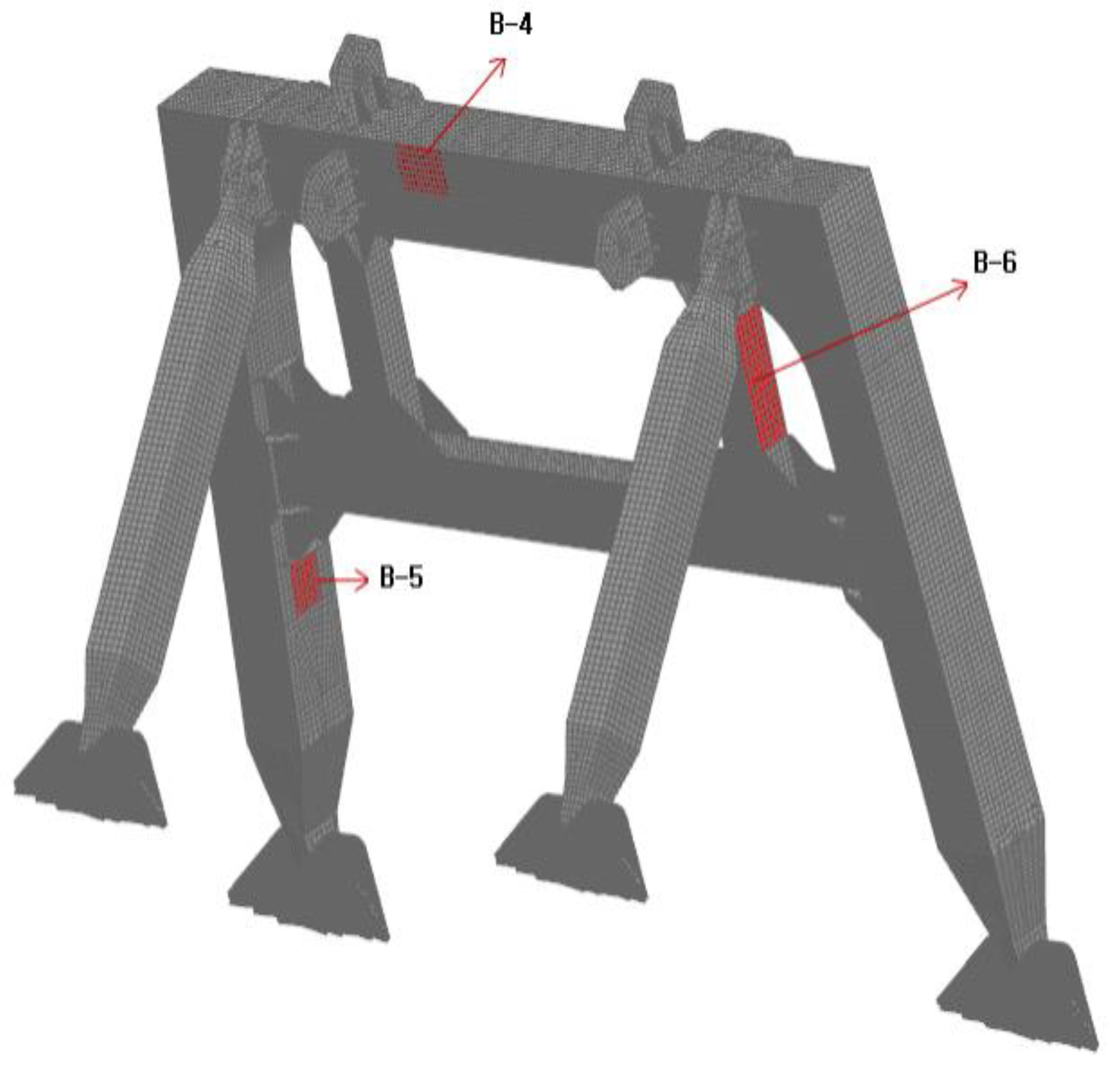
Figure 13 shows the assessment positions for the buckling stress of the boom and Figure 14 shows the assessment positions of buckling stress of the back tower. For such assessment positions of buckling stress, the assessment has been conducted mainly on the parts that receive the compression through the screening process based on the result of stress analysis. As a result, shown as the arrangement in Table 12, as the buckling coefficient of a structural member exceeds 1.0, it has been found out that the buckling did not occur. In this table, a and b mean the measurements of panel members (long width a, short width b) and t means the thickness of the panel. means the material constant defined in the KR rules, while 0.72 and 0.78 are the constants for HT36 steel and HT32 steel, respectively. is the component of equivalent stress that represents the von-Mises stress.
ABS specifies a buckling state limit in which members subjected to axial compression or combined loads, such as axial compression and bending moment, are to be assessed in accordance with their requirements [31]. Assessment performed in accordance with other applicable standards will be subject to special consideration.
For the buckling state limit of plates subjected to in-plane and lateral pressure loads, the following strength criterion is to be satisfied:
Here, is the critical buckling stress for uniaxial compression in the longitudinal direction. is the critical buckling stress for uniaxial compression in the transverse direction. is the critical buckling stress for edge shear. is the maximum allowable strength utilization factor, as defined in Subsection 1/11 and 3/1.7 of the rule [31]. is the maximum compressive stress in the longitudinal direction. is the maximum compressive stress in the transverse direction, and is the edge shear stress.
The maximum allowable strength utilization factor is defined based on load conditions representing various operation modes of offshore structures. Sun and Spencer [32] summarized the utilization factor in relation to local plate buckling as 0.6 for normal operations and 0.8 for severe storm conditions. Sun and Tan [33] presented the lowest utilization factor on offshore structures as 0.6 from ABS documents for mobile offshore drilling units [34] and floating production installations [35]. Therefore, this value was applied to determine whether buckling was according to ABS regulations in this study. As a result, the largest value on the left side in Equation (5) was about 0.423 in case of the B-1 plate, as shown in Table 13. From this table, the maximum value calculated in Equation (5) for the rest of the plates was 0.055 in case of the B-5 plate. These results for the ABS’s buckling criteria mean that the six target plates are safe from buckling.
Therefore, DNVGL [30] regulates the elastic buckling safety factors for about three load cases, respectively; Case I: 1.86, Case II: 1.66, and Case III: 1.38. The elastic buckling allowable stresses (unit: MPa) of AH32 are Case I: 169, Case II: 190, and Case III: 228, and AH36 has Case I: 191, Case II: 214, and Case III: 257. The combined stress results of the boom and the back tower satisfy the DNVGL elastic buckling design criteria for all the load cases in Table 11.
4.4. Discussion and Limitations
In this study, a design to minimize the luffing angle was conducted as a way to increase the utilization rate of floating cranes. Section 2.2 summarizes additional considerations. In addition, the structural safety was evaluated in terms of deformation, stress, and buckling using finite element analysis based on the classification society’s rule (from Section 4.1 to Section 4.3). These safety assessments by using finite element analysis results can be said to be a universal procedure for the ship structure [36,37,38,39]. However, the question of how far the safety assessment procedure of floating cranes conducted in this study can be applied may be concerning.
When applying the methodology of this study, the key to be considered is the formal identity of floating cranes. In other words, the crane should be installed on the barge or monohull, and the crane type should be applied with the boom (or truss) and back tower method. It is considered that the methodology of this study can be applied to floating cranes of less than about 4000 tons that are used for offshore work adjacent to land from this point of view, as mentioned in Section 2.2. On the other hand, higher profits can be expected by increasing the utilization rate from the perspective of crane managers, so it is expected that the solution proposed in this study will be actively employed. However, there remains a problem to consider both the expectation of profits from lowering the luffing angle and the increase in cost of installing extra equipment (hydraulic cylinders, etc.).
The safety of the upper structure of the floating crane, which was developed mainly based on the relevant regulations of the Korean Register of Shipping, was evaluated in this study. In addition, evaluation criteria of DNVGL and ABS were also applied to check out the appropriateness of this safety assessment. As a result, both the stress and buckling strength evaluation were found to be safe. However, it was investigated that there is no explicit deformation allowance standard regarding the deformation within the regulations related to the cranes of the two classification societies. Nevertheless, the deformation tolerance standard (span/800 or less) applied in this study seems to be appropriate because it is considered to be a general deformation tolerance range.
The lower hull (barge) is not covered in this study. Considering the effect of the luffing angle minimization design on the barge, it is considered that the possibility of capsizing due to the movement of the center of gravity in very lower luffing operation should be reviewed. When navigating under the marine bridge while maintaining the minimum luffing angle, a relatively large incline in the forward or backward direction of the crane may occur due to changes in the forward speed and center of gravity. This problem can be accurately predicted and solved by analyzing the movement characteristics of the barge due to external force [40]. A relatively simple solution would also be useful to increase the reserve buoyancy in the direction of the barge where the boom moves.
In addition, one of the issues not addressed in the safety aspect of the developed barge could be a safety review by fatigue load. Floating cranes are not regularly operated along a specific route, but they are usually moved depending on the work demand. The normal operating environment of floating cranes will be relatively gentle seas, not rough seas. Considering the above two points, it seems that the possibility of fatigue damage caused by repetitive loads such as waves in a specific part of the crane is very low. However, if the luffing angle is minimized, the reaction force may increase at the supporting point of the wire connected to the boom, as mentioned in Section 2.2, and this increased reaction force and repeated luffing operation may cause a low cycled fatigue problem.
Finally, a safety review by accidental loads in collision or grounding was also excluded from this study [41,42]. It can be said that this is related to the limitations of the floating crane’s movement while operating in water areas, as discussed in the previous paragraph. In other words, collision or grounding accidents are likely to occur in complex maritime traffic conditions, including bad weather due to fog, storm, and so on. Meanwhile, the floating crane will move away from fog or bad weather, and its operating water area will be relatively gentle. So, accidental loads due to collision and grounding of the barge do not seem to be essential safety review items. However, there is a possibility of an accident when passing under a marine bridge covered in this study [43,44]. However, most of the crane vessels will comply with the safe passage height and keep at relatively low speed when passing under a bridge, as in the case of the vessel introduced in Section 1.
5. Conclusions
Recently, the demand for floating cranes has been increased for the assembly and erection of giant blocks in shipbuilding, the installation and operation of giant marine structures including marine wind power, and the salvage of stranded and sunken ships. The limitation of movement on the sea may occur for the floating crane that moves and works around the coastal areas due to marine bridges if there are many islands with several marine bridges.
Accordingly, a measure to minimize the luffing angle has been reflected on the design of a floating crane, in order to pass through more marine bridges, as mentioned in Section 2. Through this measure, it will be possible to raise the operation rate of the floating crane by reducing the restriction on the navigation under marine bridges.
In order to review the structural safety of the developed floating crane, the structural stress and combined stress occurred by the use of a floating crane under the stowage and luffing conditions have been evaluated in Section 3 and Section 4. As in Section 4.3, the buckling stress has been evaluated around the members where the considerable compression occurs by reducing the luffing angle. Through such study, the following conclusion has been obtained.
- (1)
- The floating crane has been designed by reflecting the minimum luffing angle, which has considered the movement on the sea. Additionally, from the result of structural analysis on the boom, back tower, and support members under the luffing condition, high reaction force and fatigue may be increased in the boom closer to the horizontal angle. As the additional load of a hydraulic cylinder is applied, which is used for the recovery of luffing angle in the service condition, it has been found out that the process of an assessment on the structural stress must be considered.
- (2)
- From the result of a review from the aspect of allowable stress, deformation, and buckling with the application of KR rules to the designed floating crane, it has been evaluated such that overall safety was secured. As shown from the results of Section 4.2, the stress occurred in the luffing condition has shown the same stress level as that in the service condition. The deformation of the boom covered in Section 4.1 has shown the highest in the service condition, and the deformation of the back tower has shown the highest in the luffing condition. In addition, the reaction force increased in the upper part of the boom and the support in the luffing condition. The compression force increased at the center of the boom, but buckling did not occur from the result of an assessment.
- (3)
- According to Section 2.2, the number of marine bridges listed in Table 1 that can pass through it has increased very significantly if the boom height is reduced to the level of the back tower by lowering the minimum luffing angle in case of 2200 ton and 3000 ton cranes. This means that the utilization rate of the crane can be increased, and it is a great advantage for the operating company. In addition, the estimation of the reaction force in the boom-connecting wire in the minimum luffing condition and the load combination including luffing condition and procedure for safety assessment performed in this study can be applied to a large crane (about up to 4000 tons class) with a barge or monohull as a lower hull.
Author Contributions
Conceptualization, J.-H.L. and T.-K.L.; methodology, M.-W.L. and J.-H.L. software, M.-W.L.; validation, H.-J.P., T.-K.L. and Y.-S.L.; formal analysis, M.-W.L.; investigation, H.-J.P., T.-K.L. and M.-W.L.; resources, J.-H.L. and Y.-S.L.; data curation, M.-W.L. and T.-K.L.; writing—original draft preparation, M.-W.L. and T.-K.L.; writing—review and editing, H.-J.P., Y.-S.L. and T.-K.L.; visualization, M.-W.L. and H.-J.P.; supervision, J.-H.L. and T.-K.L.; project administration, J.-H.L. and T.-K.L. All authors have read and agreed to the published version of the manuscript.
Funding
This research received no external funding.
Institutional Review Board Statement
Not applicable.
Informed Consent Statement
Not applicable.
Data Availability Statement
Not applicable.
Conflicts of Interest
The authors declare no conflict of interest.
References
- Ministry of Employment and Labor (MOEL). Safety Inspection Notice, 2020; No. 2020-43; MOEL: Seoul, Korea, 2020.
- Shepherd, G.; Kahler, R.; Cross, J. Crane fatalities—A taxonomic analysis. Saf. Sci. 2000, 36, 83–93. [Google Scholar] [CrossRef]
- King, A. Analysis of Crane and Lifting Accidents in North America from 2004 to 2010. University of Texas, USA. 2012. Available online: https://dspace.mit.edu/handle/1721.1/73792 (accessed on 10 May 2021).
- Milazzo, M.F.; Ancione, G.; Spasojevic Brkic, V.; Vališ, D. Investigation of crane operation safety by analysing main accident causes. In Risk, Reliability and Safety: Innovating Theory and Practice, Proceedings of the 26th European Safety and Reliability Conference, ESREL 2016, Glasgow, Scotland, 25–29 September 2016; Walls, L., Revie, M., Bedford, T., Eds.; CRC Press/Balkema: London, UK, 2017; p. 15. Available online: https://www.researchgate.net/publication/311439947 (accessed on 10 May 2021).
- Aneziris, O.; Papazoglou, I.; Mud, M.; Damen, M.; Kuiper, J.; Baksteen, H.; Ale, B.; Bellamy, L.; Hale, A.; Bloemhoff, A.; et al. Towards risk assessment for crane activities. Saf. Sci. 2008, 46, 872–884. [Google Scholar] [CrossRef]
- Ancione, G.; Paltrinieri, N.; Milazzo, M.F. Integrating Real-Time Monitoring Data in Risk Assessment for Crane Related Offshore Operations. J. Mar. Sci. Eng. 2020, 8, 532. [Google Scholar] [CrossRef]
- Milazzo, M.; Ancione, G.; Consolo, G. Human Factors Modelling Approach: Application to a Safety Device Supporting Crane Operations in Major Hazard Industries. Sustainability 2021, 13, 2304. [Google Scholar] [CrossRef]
- Lingard, H.; Cooke, T.; Zelic, G.; Harley, J. A qualitative analysis of crane safety incident causation in the Australian construction industry. Saf. Sci. 2021, 133, 105028. [Google Scholar] [CrossRef]
- Cha, J.-H.; Park, K.-P.; Lee, K.-Y. Numerical Analysis for Nonlinear Static and Dynamic Responses of Floating Crane with Elastic Boom. Trans. Korean Soc. Mech. Eng. A 2010, 34, 501–509. [Google Scholar] [CrossRef]
- Hong, J.W.; Roh, M.I.; Ham, S.H.; Ha, S. Dynamic simulation of subsea equipment installation using offshore support vessel based on flexible multibody system dynamics. J. Mar. Sci. Technol. 2016, 24, 807–821. Available online: http://jmst.ntou.edu.tw/marine/24-4/807-821.pdf (accessed on 10 May 2021).
- Sun, Y.G.; Qiang, H.Y.; Xu, J.; Dong, D.S. The nonlinear dynamics and anti-sway tracking control for offshore container crane on a mobile harbor. J. Mar. Sci. Technol. 2017, 25, 656–665. Available online: https://jmst.ntou.edu.tw/marine/25-6/656-665.pdf (accessed on 10 May 2021).
- Yang, X.R.; Gan, Q.M.; Wang, Y.H.; Zhou, Y.B. Dynamic reliability analysis of the crane ship lifting load system. J. Mar. Sci. Technol. 2017, 25, 552–562. Available online: https://jmst.ntou.edu.tw/marine/25-5/552-562.pdf (accessed on 10 May 2021).
- Yang, X.R.; Gan, Q.M.; Wang, Y.H.; Wang, G.D. Dynamic response analysis of the lifting load system of a crane ship in irregular waves. J. Mar. Sci. Technol. 2019, 27, 481–497. Available online: https://jmst.ntou.edu.tw/marine/27-6/481-497.pdf (accessed on 10 May 2021).
- Nam, M.; Kim, J.; Lee, J.; Kim, D.; Lee, D.; Lee, J. Cooperative control system of the floating cranes for the dual lifting. Int. J. Nav. Arch. Ocean Eng. 2018, 10, 95–102. [Google Scholar] [CrossRef]
- Cha, J.-H.; Park, K.-P.; Lee, K.-Y. Development of a simulation framework and applications to new production processes in shipyards. Comput. Des. 2012, 44, 241–252. [Google Scholar] [CrossRef]
- Bae, J.; Cha, J.; Seo, M.-G.; Lee, K.; Lee, J.; Ku, N. Experimental Study on Development of Mooring Simulator for Multi Floating Cranes. J. Mar. Sci. Eng. 2021, 9, 344. [Google Scholar] [CrossRef]
- Park, C.H.; Kim, B.W.; Ha, M.K.; Chun, M.S. A basic structural design for large floating crane. J. Ocean Eng. Technol. 2005, 19, 71–76. Available online: https://www.joet.org/journal/view.php?number=2597 (accessed on 10 May 2021).
- Kang, Y.G.; Beak, S.H.; Lee, J.H.; Park, W.J.; Sim, D.S.; An, Y.T.; Cho, P.S. The hull strength assessment for heavy lift floating crane. Soc. Nav. Archit. Korea 2015, 9, 1–8. Available online: https://www.koreascience.or.kr/article/CFKO201522355580734.pdf (accessed on 10 May 2021).
- Choi, H.C.; Kim, S.W. A Study on the safe maneuvering of group towing for floating crane. In Proceedings of the Autumn Annual Conference for Korean Institute of Navigation and Port Research, Pusan, Korea, 21–23 October 2010; pp. 38–39. [Google Scholar]
- Sun, G.; Liu, J. Dynamic responses of hydraulic crane during luffing motion. Mech. Mach. Theory 2006, 41, 1273–1288. [Google Scholar] [CrossRef]
- Lee, M.J.; Han, D.S.; Han, G.J. Evaluation of Structural Stability of Jib Crane for A Feed Vessel According to the Luffing Angle. J. Korea Soc. Power Syst. Eng. 2008, 12, 24–28. Available online: https://www.koreascience.or.kr/article/JAKO200806942469751.pdf (accessed on 10 May 2021).
- Zhou, Q.C.; Li, W.J.; Wu, Q.L.; Xiong, X.L. Nonlinear Calculating Method for Multi-Bar Luffing System of Giant Crane Considering the Sagging Effect. Appl. Mech. Mater. 2013, 477–478, 307–314. [Google Scholar] [CrossRef]
- Song, J.W.; Lee, Y.S.; Jeong, M.; Jo, I.S. Analysis of major specifications of domestic marine bridges. In Proceedings of the Autumn Annual Conference for the Korean Institute of Navigation and Port Research, Pusan, Korea, 5–6 December 2007; pp. 266–268. [Google Scholar]
- Available online: https://en.wikipedia.org/wiki/SSCV_Sleipnir (accessed on 10 May 2021).
- Available online: https://en.wikipedia.org/wiki/Crane_vessel (accessed on 10 May 2021).
- Lee, M.J.; Han, D.S.; Lee, S.W.; Han, G.J. Analysis of Reaction Force of Jib Crane for Shipment According to Luffing Angle. In Proceedings of the Korean Society of Precision Engineering Conference, Jeju, Korea, 20–22 June 2007; pp. 527–528. Available online: https://www.koreascience.or.kr/article/CFKO200717054765322.pdf (accessed on 29 May 2021).
- Korea Register of Shipping. Rules for the Classification of Steel Ships; Pt. 9, Ch. 2, Sec. 4—Crane; Korea Register of Shipping: Busan, Korea, 2014. [Google Scholar]
- Kim, M.-S.; Lee, J.-C.; Jeong, S.-Y.; Ahn, S.-H.; Son, J.-W.; Cho, K.-J.; Song, C.-K.; Park, S.-R.; Bae, T.-H. Structure Evaluation for the Level Luffing Crane’ Boom. Trans. Korean Soc. Mech. Eng. A 2008, 32, 526–532. [Google Scholar] [CrossRef] [Green Version]
- American Bureau of Shipping. Guide for Certification of Lifting Appliances; American Bureau of Shipping: Houston, TX, USA, 2020; p. 37. [Google Scholar]
- DNVGL-ST-0378. Standard for Offshore and Platform Lifting Appliances; DNVGL: Baerum, Norway, 2016; Chapter 4.3. [Google Scholar]
- American Bureau of Shipping. Guide for Buckling and Ultimate Strength Assessment for Offshore Structures; American Bureau of Shipping: Houston, TX, USA, 2018; p. 27. [Google Scholar]
- Sun, H.-H.; Spencer, J. Buckling strength assessment of corrugated panels in offshore structures. Mar. Struct. 2005, 18, 548–565. [Google Scholar] [CrossRef]
- Sun, H.-H.; Tan, P.-L. Background of ABS Buckling Strength Assessment Criteria for Cylindrical Shells in Offshore Structures. J. Offshore Mech. Arct. Eng. 2008, 130, 021012. [Google Scholar] [CrossRef] [Green Version]
- ABS. Rules for Building and Classing Offshore Mobile Drilling Unit; American Bureau of Shipping: Houston, TX, USA, 2006. [Google Scholar]
- ABS. Guide for Building and Classing Floating Production Installations; American Bureau of Shipping: Houston, TX, USA, 2004. [Google Scholar]
- Rahman, M.M.; Kamol, R.S.; Islam, R. Structural analysis of a ship on global aspect using ANSYS. In Proceedings of the 1st International Conference on Mechanical Engineering and Applied Science (ICMEAS 2017), Dhaka, Bangladesh, 22–23 February 2017; p. 020008. [Google Scholar]
- Wang, E.D.; Bone, J.S.; Ma, M.; Dinovitzer, A. Guidelines for Evaluation of Marine Finite Elements Analyses; Report No. SSC-475; Ship Structure Committee: Washington, DC, USA, 2019; Available online: http://www.shipstructure.org/pdf/475.pdf (accessed on 10 May 2021).
- Kim, T.Y.; Yoon, S.W.; Cho, J.H.; Jung, S.H.; Kim, M.H. Direct strength assessment of pure car and truck carrier under maximum cargo loads. J. Ocean Eng. Technol. 2019, 33, 641–647. (In Korean) [Google Scholar] [CrossRef] [Green Version]
- Kim, B.-S.; Hwang, H.-G.; Yoon, S.-W.; Kim, T.-Y.; Kang, J.-L. Development of Transporter for Marine Leisure Ship with Safety and Operation Support System. J. Ocean Eng. Technol. 2019, 33, 486–494. [Google Scholar] [CrossRef]
- Lim, J.H.; Jo, H.J. Prediction of Barge Ship Roll Response Amplitude Operator Using Machine Learning Techniques. J. Ocean Eng. Technol. 2020, 34, 167–179. [Google Scholar] [CrossRef]
- Kim, K.S.; Yoon, K.Y.; Jang, Y.S. Evaluation for Structural Safety of Offshore Structures under Accidental Loads. Comput. Struct. Eng. 2010, 23, 34–42. Available online: http://www.koreascience.kr/article/JAKO201029848350559.pdf (accessed on 10 May 2021). (In Korean).
- Ventikos, N.P.; Koimtzoglou, A.; Louzis, K.; Eliopoulou, E. Statistics for marine accidents in adverse weather conditions. In Maritime Technology and Engineering; Soares, C.G., Santos, T.A., Eds.; CRC Press: London, UK, 2014. [Google Scholar]
- Pedersen, P.T.; Chen, J.; Zhu, L. Design of bridges against ship collisions. Mar. Struct. 2020, 74, 102810. [Google Scholar] [CrossRef]
- Bae Ship Collision Risk Assessment and Sensitivity Analysis for Sea-crossing Bridges. J. Korean Soc. Civ. Eng. 2013, 33. [CrossRef] [Green Version]
Figure 1.
Vessel passing under the bridge using the luffing angle of an A-frame. (a) Drawing for check of luffing condition; (b) A marine DCM vessel passing under the TM-CLKL Bridge.
Figure 1.
Vessel passing under the bridge using the luffing angle of an A-frame. (a) Drawing for check of luffing condition; (b) A marine DCM vessel passing under the TM-CLKL Bridge.
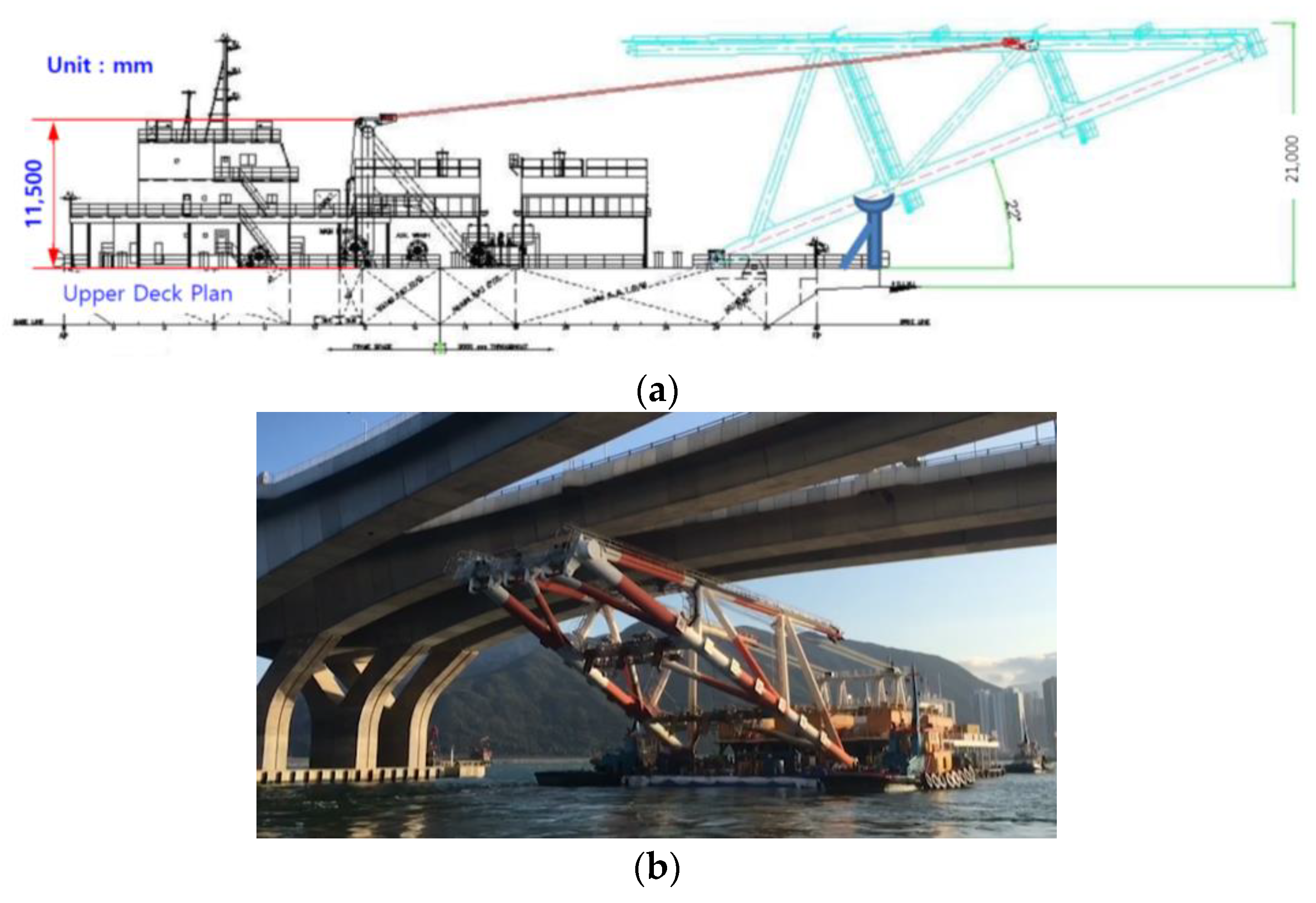
Figure 2.
Explanation of boom height, back tower height, and minimum luffing angle for a floating crane.
Figure 2.
Explanation of boom height, back tower height, and minimum luffing angle for a floating crane.
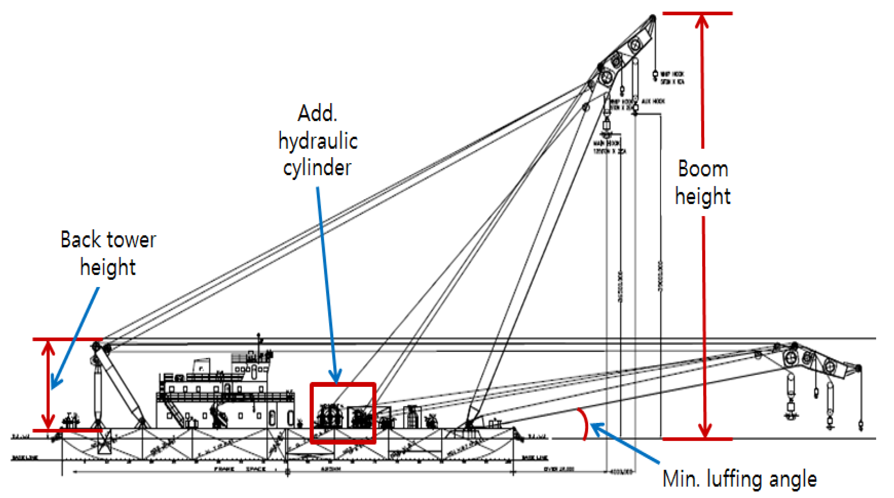
Figure 3.
Position of reaction force for boom.

Figure 4.
Reaction force of the boom by luffing angle and CLC.

Figure 5.
CLC7 of boom structure.

Figure 6.
CLC7 of boom structure.
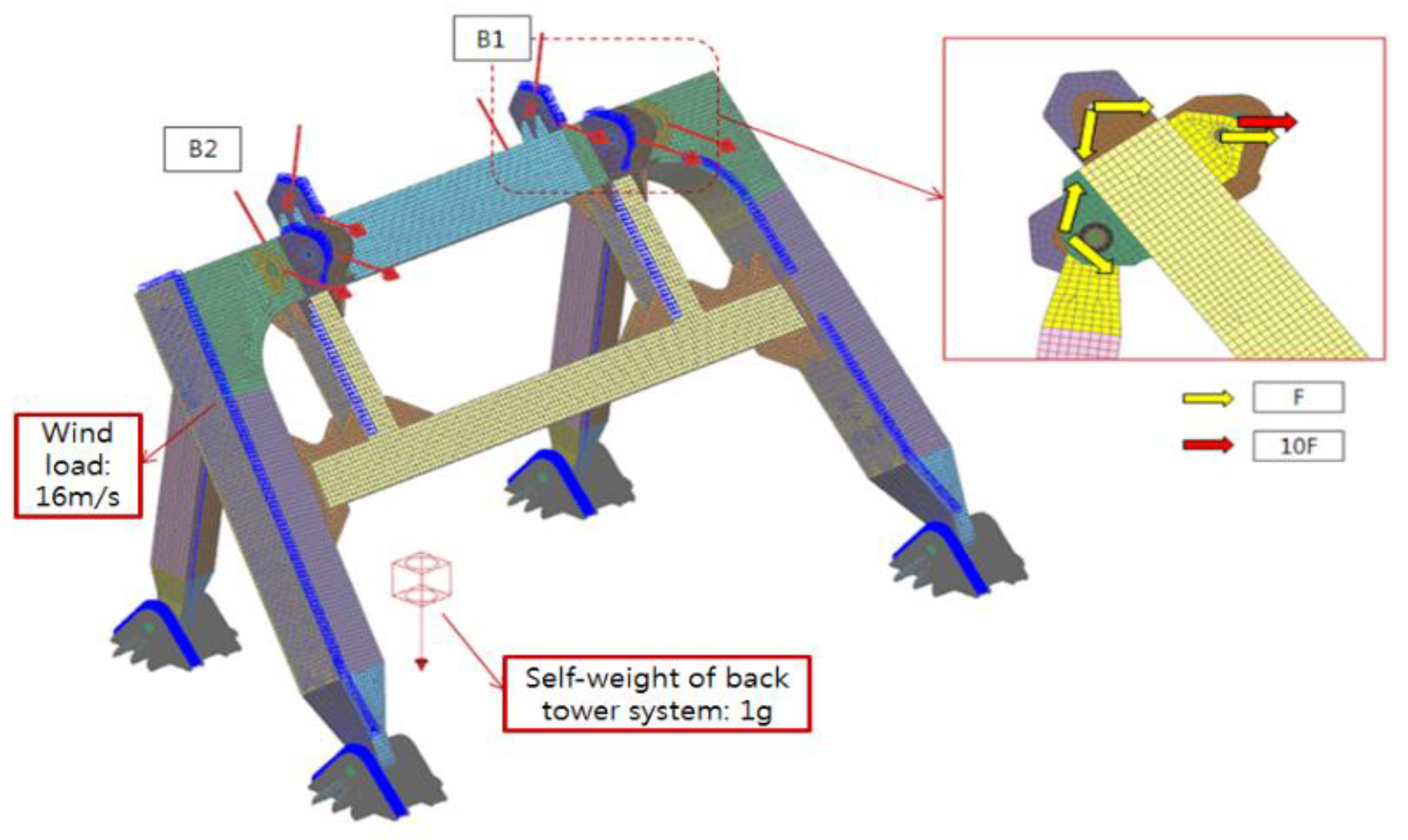
Figure 7.
FE model of boom structure.
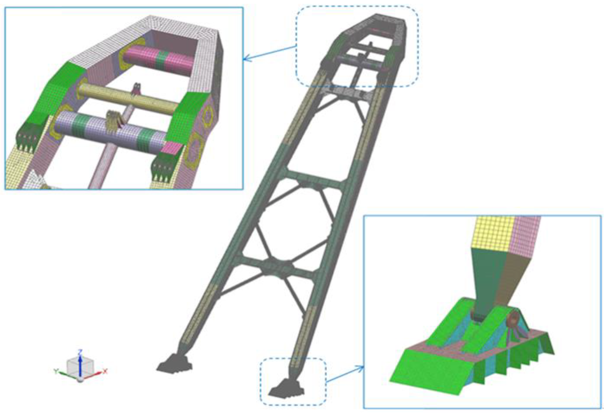
Figure 8.
FE model of back tower structure.
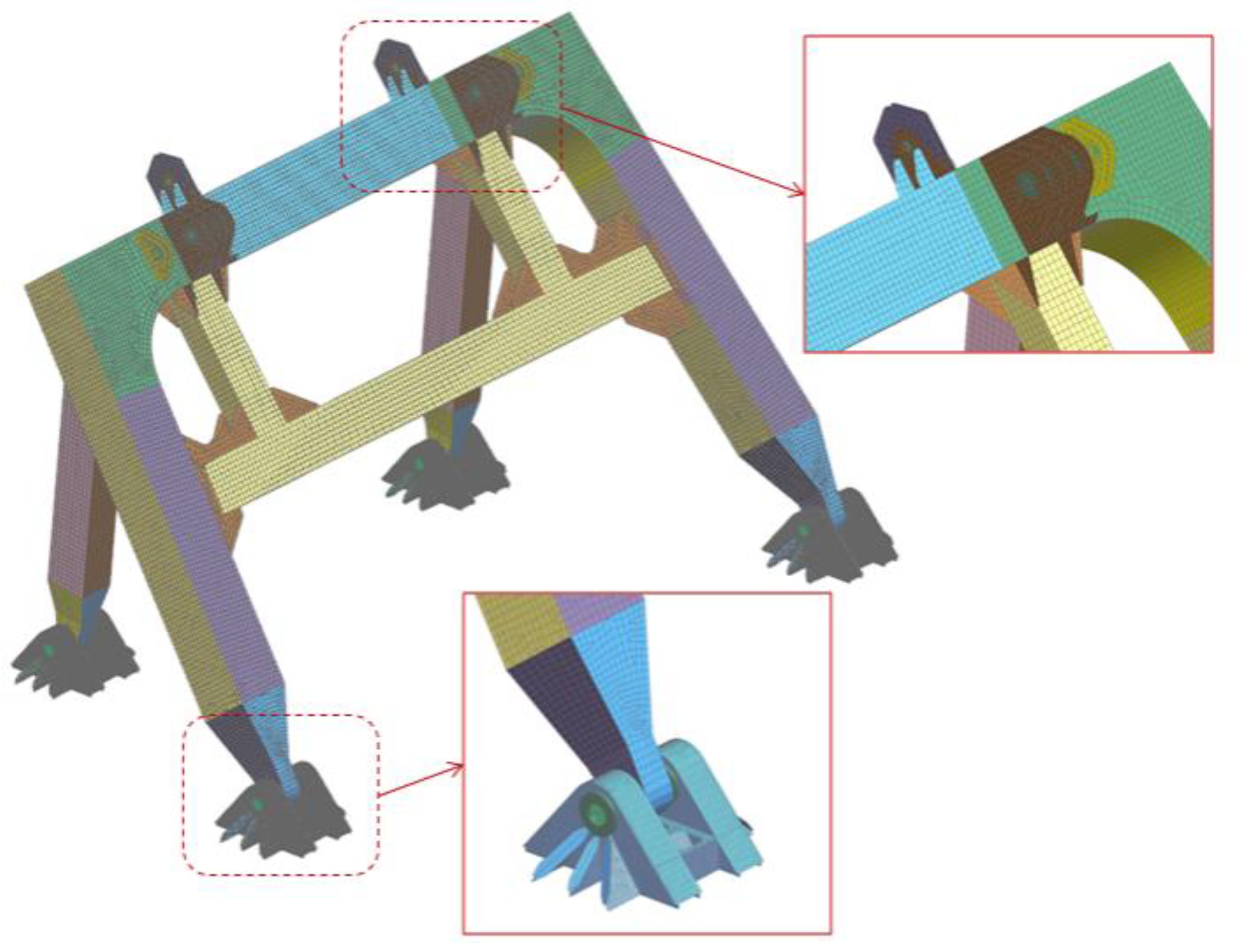
Figure 9.
Boundary conditions for boom in CLC1–6.

Figure 10.
Boundary conditions for boom in CLC1–7.

Figure 11.
Displacement of Z-axis for boom (CLC1).
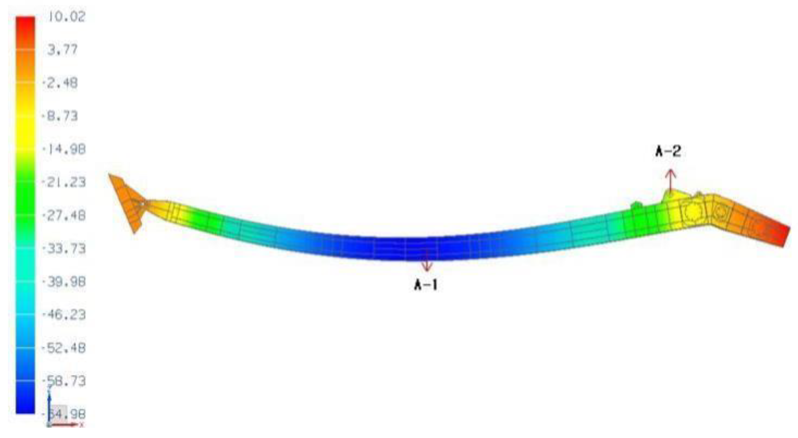
Figure 12.
Displacement of X-axis for back tower.
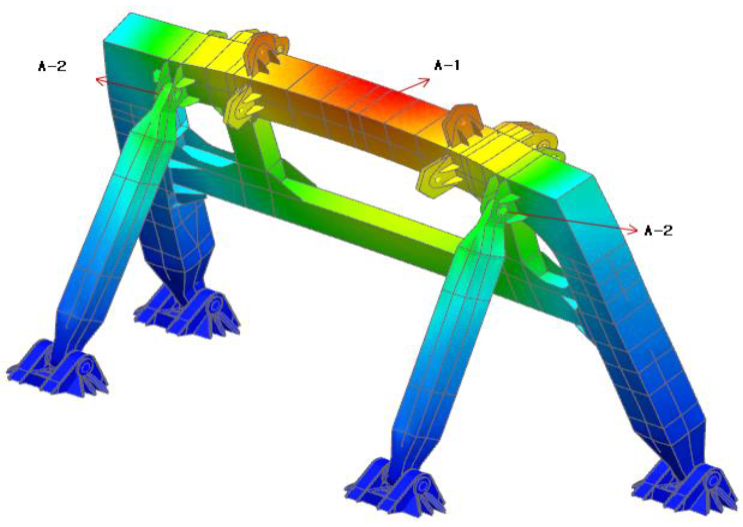
Figure 13.
Positions for buckling calculation of the boom.

Figure 14.
Positions for buckling calculation of the back tower.

Table 1.
Specifications of major domestic marine bridges.
| Bridge Name | Bridge Type | Min Span Length (m) | Clearance under Bridge (m) |
|---|---|---|---|
| Youngjong | suspension | 300 | 40 |
| Seohae | cable stayed | 470 | 62 |
| Mokpo | cable stayed | 500 | 53 |
| Machang | cable stayed | 400 | 64 |
| Kwangyang | suspension | 1545 | 75 (85, center) |
| Bukhang | cable stayed | 540 | 60 |
| Ulsan | cable stayed | 560 | 60 |
| Geoga | cable stayed | 470 (main) 230 (sub) | 52 36 |
| Incheon | cable stayed | 800 | 70.4 |
Table 2.
Specification of major domestic floating cranes.
| Capacity (ton) | Min. Luffing Angle (deg) | Boom Height (m) | Back Tower Height (m) | Remark |
|---|---|---|---|---|
| 120 | 50.5 | 50 | 22 | |
| 600 | 40 | 38 | - | Salko Co. |
| 1200 | 30 | 41.8 | 36.5 | Salko Co. |
| 2000 | 35 | 48 | 40 | Haekwan |
| 2200 | 40 | 56.1 | 34.5 | Kumyong |
| 3000 | 40 | 76.6 | 45 | SHI * |
* SHI: Samsung Heavy Industries, Ltd.
Table 3.
Wind pressure under service condition for boom.
| Height (m) | Velocity (m/s) | Shape Factor ( ) | Height Factor ( ) | Wind Pressure (Pa) |
|---|---|---|---|---|
| 18.1 | 16 | 1.2 | 1.1 | 207.2 |
| 30.9 | 16 | 1.2 | 1.2 | 226.0 |
| 42.8 | 16 | 1.3 | 1.2 | 244.9 |
| 49.2 | 16 | 1.3 | 1.2 | 244.9 |
| 51.9 | 16 | 1.4 | 1.3 | 285.7 |
Table 4.
Wind pressure under stowage condition for boom.
| Height (m) | Velocity (m/s) | Shape Factor ( ) | Height Factor ( ) | Wind Pressure (Pa) |
|---|---|---|---|---|
| 18.1 | 25.8 | 1.2 | 1.1 | 538.7 |
| 30.9 | 25.8 | 1.2 | 1.2 | 587.7 |
| 42.8 | 25.8 | 1.3 | 1.2 | 636.7 |
| 49.2 | 25.8 | 1.3 | 1.2 | 636.7 |
| 51.9 | 25.8 | 1.4 | 1.3 | 742.8 |
Table 5.
Wind pressure under service condition for back tower.
| Height (m) | Velocity (m/s) | Shape Factor ( ) | Height Factor ( ) | Wind Pressure (Pa) |
|---|---|---|---|---|
| 14.0 | 16 | 1.3 | 1 | 204.0 |
Table 6.
Wind pressure under stowage condition for back tower.
| Height (m) | Velocity (m/s) | Shape Factor ( ) | Height Factor ( ) | Wind Pressure (Pa) |
|---|---|---|---|---|
| 14.0 | 25.8 | 1.3 | 1 | 530.6 |
Table 7.
Design loads for crane.
| No. | Design Load |
|---|---|
| A | Safe working load of the crane 250 t |
| B | Safe working load of the crane 100 t |
| C | Additional impact loads |
| D | Self-weight of crane system and fittings attached |
| E | Self-weight of loose gear |
| F | Friction of cargo blocks |
| G | Wind loading 16 m/s, service conditions |
| H | Wind loading 25.8 m/s, stowage conditions |
| I | Loads due to ship inclination in service conditions |
| J | Loads due to ship inclination in stowage conditions |
| K | Loads due to ship motion + 0.5 g (Z-dir.), 0.25 g in the longitudinal direction (X-dir.) |
| L | Loads due to ship motion + 0.5 g (Z-dir.), 0.25 g in the transverse direction (Y-dir.) |
| M | Cylinder force (100 × 4 = 400 t) |
| N | Force of the upper sheave of back tower |
| O | Self-weight of back tower |
Table 8.
Combination of boom design loads.
| No. | Combined Load Conditions (CLC) | ||||||
|---|---|---|---|---|---|---|---|
| CLC1 | CLC2 | CLC3 | CLC4 | CLC5 | CLC6 | CLC7 | |
| A | ● | ● | |||||
| B | ● | ● | |||||
| C | ● | ● | ● | ● | |||
| D | ● | ● | ● | ● | ● | ● | ● |
| E | ● | ● | ● | ● | ● | ● | ● |
| F | ● | ● | ● | ● | |||
| G | ● | ● | ● | ● | |||
| H | ● | ● | |||||
| I | ● | ● | ● | ● | |||
| J | ● | ● | |||||
| K | ● | ● | ● | ||||
| L | ● | ● | ● | ||||
| M | ● | ||||||
Table 9.
Combination of back tower design loads.
| No. | Combined Load Conditions | ||||||
|---|---|---|---|---|---|---|---|
| CLC1 | CLC2 | CLC3 | CLC4 | CLC5 | CLC6 | CLC7 | |
| N | ● | ● | ● | ● | ● | ● | ● |
| O | ● | ● | ● | ● | ● | ● | ● |
| G | ● | ● | ● | ● | ● | ||
| H | ● | ● | |||||
| I | ● | ● | ● | ● | |||
| J | ● | ● | |||||
| K | ● | ● | ● | ||||
| L | ● | ● | ● | ||||
Table 10.
Allowable stress for AH32 and AH36 (unit: MPa).
| Load Condition | Mat. | Kind of Stress | |||
|---|---|---|---|---|---|
| Tension | Shear | Compression | Combined | ||
| CLC 1–4 | AH32 | 242.6 | 141.8 | 211.1 | 280.4 |
| CLC7 | AH36 | 273.6 | 159.8 | 237.9 | 316.0 |
| CLC 5–6 | AH32 | 274.1 | 157.5 | 239.4 | 315.0 |
| AH36 | 308.9 | 177.5 | 269.8 | 355.0 | |
Table 11.
Maximum combined stress for boom and back tower (unit: MPa).
| 0 | 1 | 2 | 3 | 4 | 5 | 6 | 7 |
|---|---|---|---|---|---|---|---|
| Boom | 145.3 | 148.6 | 100.7 | 115.7 | 149.9 | 201.8 | 166.8 |
| Back tower | 157.8 | 144.4 | 103.4 | 90.1 | 77.9 | 69.0 | 162.9 |
Table 12.
Results for buckling calculation of the boom and back tower (stress unit: MPa).
| Pos.no | B-1 | B-2 | B-3 | B-4 | B-5 | B-6 |
|---|---|---|---|---|---|---|
| a (mm) | 2650 | 3000 | 1200 | 1000 | 830 | 1816 |
| b (mm) | 1200 | 752 | 397 | 544 | 585 | 585 |
| t (mm) | 18 | 16 | 14 | 30 | 16 | 16 |
| fmat | 0.72 | 0.78 | 0.78 | 0.78 | 0.78 | 0.78 |
| σeq | 44.9 | 63.9 | 72.1 | 63.3 | 58.4 | 43.4 |
| σc | 162.4 | 306.2 | 287.0 | 305.4 | 274.6 | 295.9 |
| λ | 3.620 | 4.790 | 3.979 | 4.826 | 4.705 | 6.825 |
| check | OK | OK | OK | OK | OK | OK |
Table 13.
Results for buckling calculation by ABS rule (stress unit: MPa).
| Pos.no | B-1 | B-2 | B-3 | B-4 | B-5 | B-6 |
|---|---|---|---|---|---|---|
| 45.4 | −63.0 | 75.0 | −1.9 | −58.9 | −43.9 | |
| 1.1 | 1.8 | 6.1 | −64.2 | −1.1 | −1.1 | |
| 3.2 | 5.9 | 3.2 | −0.6 | −7.3 | 0.6 | |
| 164.4 | 2778.8 | 922.0 | 77.2 | 619.6 | 1317.1 | |
| 4 | −79.4 | 75.0 | 2608.8 | 11.6 | 33.0 | |
| 165.89 | 165.02 | 175.93 | 172.72 | 174.09 | 171.96 | |
| Equation (5) | 0.423 | 0.0064 | 0.0377 | 0.0034 | 0.055 | 0.0062 |
| check | OK | OK | OK | OK | OK | OK |
Publisher’s Note: MDPI stays neutral with regard to jurisdictional claims in published maps and institutional affiliations. |
© 2021 by the authors. Licensee MDPI, Basel, Switzerland. This article is an open access article distributed under the terms and conditions of the Creative Commons Attribution (CC BY) license (https://creativecommons.org/licenses/by/4.0/).
Share and Cite
MDPI and ACS Style
Lee, M.-W.; Lee, J.-H.; Lee, Y.-S.; Park, H.-J.; Lee, T.-K. Safety Assessment for Upper Part of Floating Crane Considering Minimum Luffing Angle. Appl. Sci. 2021, 11, 5104. https://doi.org/10.3390/app11115104
AMA Style
Lee M-W, Lee J-H, Lee Y-S, Park H-J, Lee T-K. Safety Assessment for Upper Part of Floating Crane Considering Minimum Luffing Angle. Applied Sciences. 2021; 11(11):5104. https://doi.org/10.3390/app11115104
Chicago/Turabian StyleLee, Min-Woo, Ji-Hyun Lee, Yeon-Seung Lee, Hyun-Jin Park, and Tak-Kee Lee. 2021. "Safety Assessment for Upper Part of Floating Crane Considering Minimum Luffing Angle" Applied Sciences 11, no. 11: 5104. https://doi.org/10.3390/app11115104
Note that from the first issue of 2016, this journal uses article numbers instead of page numbers. See further details here.