
Joint Properties of Aluminum Alloy and Galvanized Steel by AC Pulse MIG Braze Welding


1
Department of Mechanical Engineering, Chosun College of Science and Technology, Gwangju 61452, Korea
2
HRC for Ppuri Smart Convergence Characterization, Chosun University, Gwangju 61452, Korea
3
Department of Welding and Joining Science Engineering, Chosun University, Gwangju 61452, Korea
*
Author to whom correspondence should be addressed.
Appl. Sci. 2021, 11(11), 5105; https://doi.org/10.3390/app11115105
Submission received: 26 April 2021
/
Revised: 20 May 2021
/
Accepted: 21 May 2021
/
Published: 31 May 2021
(This article belongs to the Topic Metallurgical and Materials Engineering)
Abstract
:In response to global environment and fuel efficiency regulations aiming to reduce CO2 emissions, multi-material structures that use lightweight materials are currently being developed to realize the weight reduction of vehicles in automotive manufacturing. The dissimilar welding of aluminum alloy to steel has great importance, but it is still challenging due to their widely varying thermo-physical properties and the formation of intermetallic compounds. This study aimed to investigate the effect of process parameters on the wettability, mechanical properties, and microstructure in AC Pulse MIG welded joints of AA6061-T6 and galvanized steel sheets. A parametric study on torch aiming position and welding current with EN ratio variation was performed to optimize the process parameters. The result showed that the amount of metal deposition increased with EN ratio. When the EN ratio was higher, the wire feeding speed increased and the heat input process lowered. Moreover, the wetting length increased, ranging from 6.6 to 8.4 mm, and the wetting angle increased from 31.2 to 67.6°, respectively. As a result of the tensile shear test, the maximum tensile shear load of dissimilar welded joints produced at 70 A with a 20% EN ratio was approximately 8.8 kN. From the result of scanning electron microscopy with energy-dispersive spectrometry, FeAl3 IMC was observed at the joint interface, and the IMC layer thickness decreased with EN ratio at 70 A.
1. Introduction
Recently, an environmental problem, global warming, has recently been in the spotlight. Thus, the automotive industry has been under strict emission gas regulations. Lightweight materials (LM), such as aluminum (Al) alloys, magnesium (Mg) alloys, ultra-high-strength steels (UHSS), and carbon fiber-reinforced plastics (CFRP), are extensively used as a way to improve fuel economy, so the joining technology of aluminum (Al) alloy and steel can play an important role. Al alloy and steel have different physical properties, so they are difficult to join. In addition, intermetallic compounds (IMCs) are easily generated at the joint interface, which is significantly brittle. Due to the formation of brittle intermetallic compounds, the weld is weakened and the strength decreases. Therefore, it is necessary to reduce the generation of intermetallic compounds, and a low-heat input process is required as a solution. One of the processes is AC Pulse MIG brazing. The higher the EN ratio, the faster the wire feed rate. Therefore, a low heat generation process that can reduce the occurrence of IMCs becomes possible. Yagati et al. studied the dissimilar joining of an Al alloy to galvanized steel (GI), galvanized steel (GA), and uncoated steel using double pulse MIG welding. They reported that the spreadability and wettability of the filler wire were significantly improved due to the zinc (Zn) layer, when the hot-dip GI steel sheet was used to join the dissimilar materials. The highest tensile shear strength was obtained using the GI steel sheet [1]. The lap joining of a 1 mm-thick Al alloy and stainless steel (STS) was performed to examine the effect of an aluminizing coating and galvanized zinc coating on spreadability via MIG braze-welding using 4043 Al-Si filler wire [2]. They reported that micro-cracks were observed in the aluminized coating zone, whereas the appearance of an excellent formation was observed in the galvanized coating. The highest tensile strength was approximately 193 MPa when the galvanized steel coating was selected. Kim et al. performed dissimilar braze-welding of a 1.2 mm-thick AA5052 alloy to GA, GI, and a SPCC steel sheet using cold metal transfer (CMT) welding. They reported that their joining properties significantly depended on the type of coating. Especially, in the case of GA steel, the coating layer did not sufficiently melt, due to its higher melting point when compared with GI steel. In addition, when the thickness of the coating layer increased, the metal deposition amount decreased by up to 5% and the tensile shear load decreased by 25% [3]. Murakami et al. reported the growth mechanism of the IMC layer using DC pulsed MIG arc brazing with flux-cored Al-Si filler wire. The maximum tensile strength was approximately 80 MPa with an IMC layer thickness of less than 2.5 µm [4].
In this sense, the formation of an excessive IMC layer in dissimilar braze-welded joints caused the decrease in weld strength, and, therefore, dissimilar joining technology is required to suppress the excessive growth of the IMC layer. Among the low-heat-input processes, AC pulse MIG welding, which is one of promising processes based on gas metal arc welding (GMAW) for dissimilar metal joining, can effectively suppress the growth of IMC layers. AC pulse MIG welding generates a direct current electrode positive (DCEP) and direct current electrode negative (DCEN), it cyclically alternates between these sections, and its heat input can be controlled [5,6,7]. Park et al. conducted the lap joining of a 1.6 mm-thick AA6K21 alloy to 1.4 mm-thick SPRC440 steel using AC Pulse MIG welding with 4043 filler wire. They reported that the IMC layer thickness decreased with EN ratio. The tensile strength obtained at a gap of 0 mm and a EN ratio of 10% was 173 MPa, which is equal to 70% of Al alloy [6]. Cho et al. studied the joining characteristics with the variation in EN ratio using AC pulse MIG braze-welding for joining the Al alloy to the GI steel sheet. They reported that the deformation decreased with the EN ratio. Moreover, a stable bead morphology was formed at the EN ratio of 40% and the damage to the coating layer was small [8].
Therefore, in the present study, we aimed to investigate the joint properties according to the current, i.e., the heat input, by applying the AC pulse MIG braze-welding of an Al alloy (AA6061-T6) to a galvanized steel (GI) sheet.
2. Materials and Methods
In the present study, the base metals were a 2 mm-thick AA6061-T6 and a 2 mm-thick GI steel sheet whose dimensions were 200 mm (L) × 100 mm (B), as shown in Figure 1a. The AA6061-T6 and GI steel sheets were placed at the top and bottom in a lap joint configuration without a gap between the faying surfaces. Table 1 lists the chemical compositions of AA6061-T6, GI steel, and 4047 Al-Si alloy wire used for the experiment. The mechanical properties of the two base metals are given in Table 2.
An AC Pulse MIG welding machine was used to join dissimilar materials using 4047 aluminum alloy wire, and filler wire was fed with an angle of 80° and a drag angle of 10°. The outer diameter of filler wire was 1.2 mm. Before the experiment, two base metals were polished by steel brush to remove the oxide layer and were then cleaned with acetone on the surface. Argon (Ar) shielding gas was supplied with a flow rate of 18 L/min to prevent oxidation during welding. The contact-tip-to-workpiece distance (CTWD) was fixed at 15 mm. The wetting length and wetting angle of Al/Fe dissimilar metal joints were examined in terms of wettability, as defined in Figure 1b [9]. Three samples from each welded joint were prepared to measure the wetting length and wetting angle in the macrostructure image with an imaging calculator. The welding parameters used for the experiment are listed in Table 3.
In order to evaluate the joint properties of dissimilar welded joints, a tensile shear test using the rectangular specimen with an overlapping length of 30 mm and a total length of 170 mm was carried out at a crosshead speed of 1 mm/min. Three specimens from each welded joint were prepared to evaluate the average tensile shear load. For macrostructure observation using an optical microscope (OM), all samples were polished using SiC paper from 400 to 4000 grit and diamond suspensions of 9, 3, and 1 µm, and they were then etched in Tucker’s reagent (45 mL HCI + 15 mL HNO3 + 15 mL HF + 25 mL distilled water) for 10 s. Elemental analysis of the IMC layer at the interface in scanning electron microscopy (SEM) was performed using energy-dispersive spectrometry (EDS). The fracture surface of the tensile shear specimen was observed to reveal the fracture behavior using SEM.
3. Results and Discussion
3.1. Effect of Process Parameters on Wettability
3.1.1. Torch Aiming Position
The effects of the different torch aiming positions on the bead appearance, cross-sectional bead morphology, and wettability are shown in Table 4. Dissimilar braze welds were produced under the following welding parameters: welding current of 70 A with an EN ratio of 0%, welding voltage of 19 V, and welding speed of 500 mm/min. The result indicated that the torch aiming position, the distance from the edge of the Al alloy sheet, had a considerable effect on wettability and joint strength. When the torch aiming position was −1 mm, the sound joints did not form, due to unstable arc formation. In contrast, for other conditions, a uniform bead appearance was formed when the aiming position was set, ranging from 0 to +2 mm. From the observation of the formation of cross-sectional bead morphology, the total amount of metal deposition significantly increased by changing the torch, aiming from 0 to 2 mm, but the wetting length decreased with wetting angle. This result tends to be related to the wettability, spreadability, and coating layer of the steel surface when overlaying the filler metal on the steel. In the case of the torch aiming position being on 0 and 1 mm, the molten filler metal under MIG arc heat was easier to wet with the steel due to the zinc (Zn) coating layer on the steel surface, and therefore, dissimilar joints exhibited a low wetting angle and long wetting length [9,10]. This similar result was also confirmed by Niu et al. [11]. They compared with the spreadability and the wettability using Zn-coated steel and uncoated steel. The wetting angle of braze-welded joints without the Zn coating exhibited a much shorter wetting length and greater wetting angle than those of Zn-coated steel. This wettability resulted in a decrease in weld strength. When the torch aiming position was set to 2 mm, the arc covered more of the Al alloy surface with faying. As a result, compared with the torch aiming positions of 0 and 1 mm, the wetting angle increased and the wetting length decreased. From a study in the literature reported by Murakmi et al., moving the torch aiming position from steel to the Al alloy side had a positive influence, reducing significantly on the growth of the IMC layer [4]. Therefore, the torch aiming position can play an important role among the process parameters. In the present study, the +2 mm torch aiming position considered under the following results was set as the fixed parameter, and then the effect of the variations in welding current and EN ratio on the wettability and joint strength was examined.
The results obtained for torch aiming positions are summarized as follows:
- When the torch aiming position was −1 mm, dissimilar joining did not occur.
- When the torch aiming position was 0 mm, dissimilar joints were formed with a bead morphology of a right-angle triangle, but there was concavity on the bead surface, where stress concentration resulting in failure occurred during tensile loading. The maximum tensile shear load of dissimilar joints was 6.8 kN.
- In the case of the +1 mm torch aiming position, the bead morphology was similar to that for 0 mm. The maximum tensile shear load was 8.4 kN. Failure occurred at the stress concentration along the fusion line.
- For an aiming position of +2 mm, the amount of the metal deposition significantly increased compared with 0 and 1 mm. The maximum tensile shear load reached 8.5 kN, which was highest among the four torch aiming positions.
3.1.2. Variation in Welding Current and EN Ratio
In order to reveal the effects of welding current and EN ratio on wettability, parametric analysis was performed under the following welding parameters: welding current of 50–70 A with EN ratio of 0–20%, welding voltage of 19 V, and welding speed of 500 mm/min. Figure 2 illustrates the typical cross-sectional bead shape of dissimilar braze-welded joints. The results show that an increase in welding current exhibited an increase in the amount of metal deposition and bead width due to the higher heat input. Compared to 10%, 20%, and 0% (from 50 to 70 A), the 10 and 20% cases of cross-sectional bead morphology were more convex. This is related to the wire melting behavior during braze welding. When the EN ratio increased, the filler wire was directly heated and further resulted in a higher metal deposition because the wire melting speed increased. On the other hand, the heat input applied to base metal could increase at an EN ratio of 0% [6].
As shown in Figure 3, a welding defect concentrated in the root area was observed. These defects appeared with an irregular size and location in the root area with no tendency of variations in welding current and EN ratio. Welding defects, such as pores, hot cracks, unfused roots, and the lack of fusion can frequently form in the root area, especially in dissimilar braze-welding using Zn-coated steel [1,12,13,14]. This defect formed in the root area may be pores due to the evaporation of Zn from the GI steel sheet because dissimilar metal joining was carried out in a lap joint without a gap between the Al alloy and steel sheet. For the formation mechanism of these welding defects, the Zn coating on the steel surface rapidly vaporized due to a low vaporization point (906 °C) and expansion with a strong vapor pressure during braze-welding. Although Zn evaporation tried to emit through the root and toe area, the root area was covered in a molten pool, and it finally remained as pores in the root area during solidification. Especially, the root area, where the Al alloy and steel sheets were tightly joined, had a high thermal conductivity, resulting in the faster solidification, causing sufficient heat input to not transfer properly. Therefore, pores and the lack of fusion were easily formed in the root area [15,16].
The comparison of wetting angle and wetting length obtained with different welding currents and EN ratios are shown in Figure 4. The wetting length increased with welding current ranging from 50 to 70 A, and it also increased with EN ratio. However, the wetting angle increased despite the increase in wetting length. In terms of geometrical bead morphology, a low wetting angle and long wetting length exhibited a good spreadability and wettability. In the present study, the wetting angle increased with the amount of metal deposition, as the torch aiming position was set to 2 mm during braze-welding.
3.2. Mechanical Property
3.2.1. Tensile Shear Load of Braze-Welded Joints
Figure 5 shows the tensile shear load of dissimilar braze-welded joints fabricated with the above-mentioned parameters: a welding current of 50–70 A with an EN ratio of 0–20%, at a welding voltage of 19 V and welding speed of 500 mm/min. There was no great difference in tensile shear load obtained from the welding current of 50–60 A with an EN ratio of 0–20%, whereas the dissimilar braze-welded joints fabricated at the welding current of 70 A with different variations in EN ratio ranging from 0 to 20% had a significant increase in the tensile shear load. The maximum tensile shear load was 8.8 kN at a welding current of 70 A and EN ratio of 20%. This result was related to the presence of welding defects formed in the root area. Referring to Figure 3g–i, no visible welding defects were observed compared with other joints. It can be inferred that under static tensile loading, the wetting angle and the wetting length did not remarkably influence the weld strength, but the strength of the weld metal, and the stress concentration, which was caused by welding defects in root area could, were the main determining factors of the joint property. From the observation of the fractured surface of braze-welded joints after the tensile shear test, all specimens were fractured along the weld metal, where an initial crack occurred at the root arear and a crack propagated along the pores. The typical fractured surface of dissimilar braze-welded joints is shown in Figure 6.
3.2.2. Fracture Behavior of Braze-Welded Joints
In order to reveal the fracture behavior of dissimilar braze-welded joints, an SEM-EDS analysis was performed. Figure 7 indicates the SEM micrographs of each joint and the EDS spectrum results measured in the root area, which were produced at a welding current of 70 A with variations in EN ratio of 0, 10, and 20%. The result obtained from the observation of SEM can confirm the existence of a pinhole formed in the root area and a large number of pores distributed in the matrix. Generally, the porosity influencing joint properties can be divided into three types: pin hole, blow hole, and worm hole. If the solidification rate is faster than the growth rate of porosity, a very small pin hole in the bead surface is generated [3]. The size of the pin hole decreased with the EN ratio, corresponding to a higher heat input. As shown in Figure 7a–c, from the results of the composition analysis, Zn ranging from 8.85 to 1.27 wt.% was detected in the bottom area, but the pores distributed in the matrix did not have Zn, as shown in Figure 7d. Hence, pores caused by hydrogen could be easily formed because the hydrogen porosity during solidification gave liquid Al the ability to absorb a large amount of hydrogen [3]. As a result, the crack initiated at the end of thin pin holes and then it propagated along the finer pores, finally leading to a fracture perpendicular to the tensile loading direction.
3.3. Microsturucture of Interfical Layer
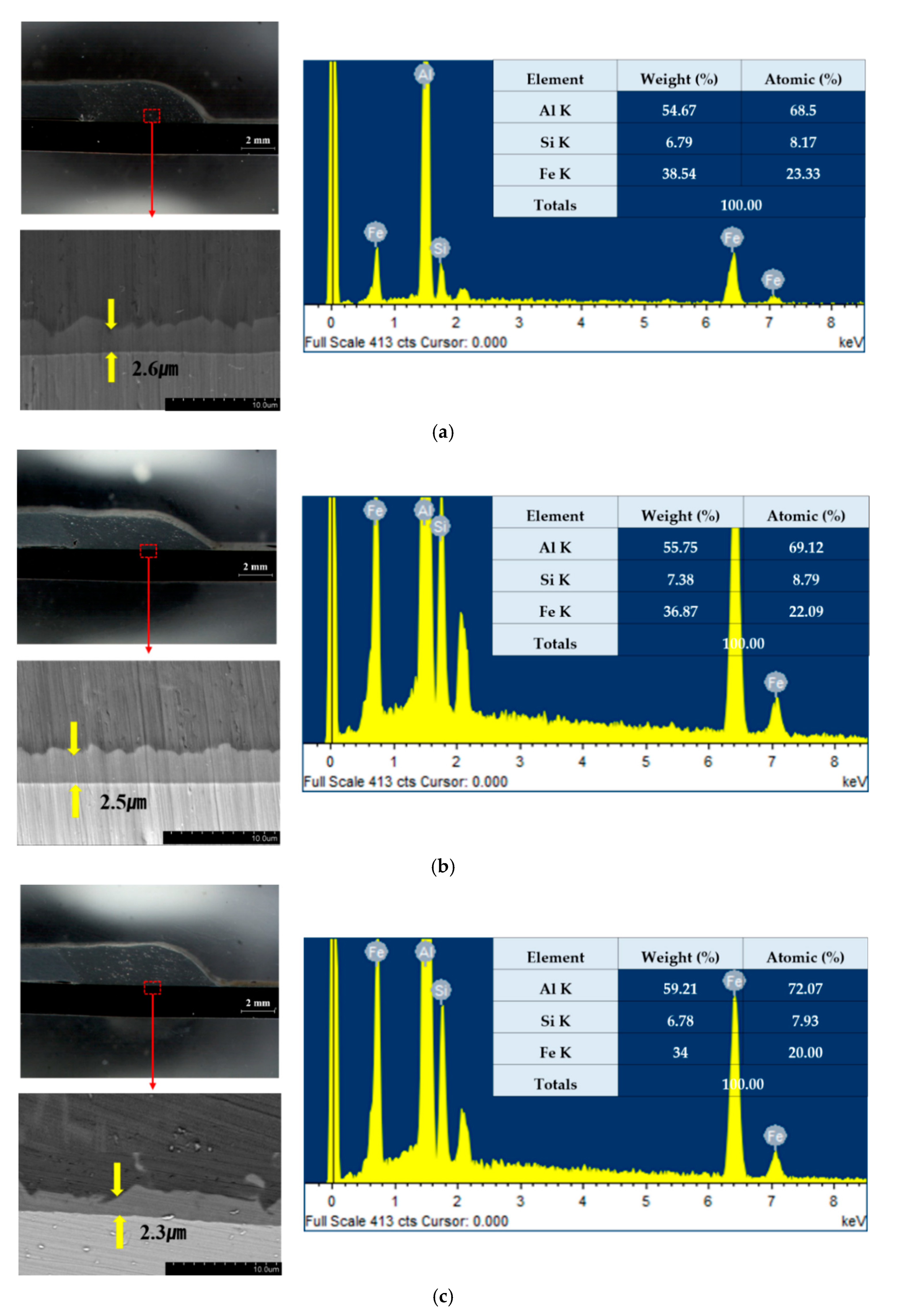
The effect of EN ratio on the variation in IMC layer thickness was measured using SEM, and composition analysis at the center of the joint interface was performed to quantitatively estimate the IMC phase based upon EDS. Figure 8 shows the SEM-EDS results of dissimilar braze-welded joints made with variations in the EN ratio of 0, 10, and 20%. The result obtained from SEM observation indicated that the IMC layer thickness slightly decreased with the increase in EN ratio from 0 to 20%. The thicknesses of the IMC layer at ENs ratio of 0, 10, and 20% were 2.6, 2.5, and 2.3 µm, respectively. This was due to the decrease in the heat input to the base metal with EN ratio. A similar result was reported by Park [6]. The formation of an excessive IMC layer at the Al/Fe joint interface significantly deteriorated the mechanical properties of dissimilar welded joints. In this sense, the IMC layer thickness can be limited to a size below 10 µm, because a thick IMC layer would cause brittleness, leading to easier crack initiation and propagation. Therefore, controlling the IMC layer thickness is a very important factor that may influence the sound weld in the dissimilar joining of the Al alloy to steel.
Dong et al. reported that the IMC layer thickness using the Al-12% Si filler wire reduced 2.5 times more than that of the Al-5% Si filler wire. Murakami et al. explained the growth mechanism of the IMC layer. The solidification of the fused weld metal, which began at the interface, affected the growth of the IMC layer thickness, because the interface was at the point of the fastest cooling rate [4]. Therefore, Si can be significantly helpful in reducing the IMC layer thickness in the dissimilar joining of the Al alloy to steel. As a result, a thin IMC layer was generated under all conditions and contributed to the higher tensile shear load, confirming that the dissimilar braze-welded joints sufficiently resisted the shear force.
4. Conclusions
In the present study, dissimilar braze-welding of a 2 mm-thick AA6061-T6 to a 2 mm-thick GI steel sheet was investigated to examine the effect of process parameters on wettability, mechanical properties, and microstructure using AC Pulse MIG welding. The results can be summarized as follows:
- Among the process parameters, the torch aiming position can play an important role in terms of spreadability and wettability. When the torch aiming position was 2 mm, the amount of metal deposition significantly increased. The maximum tensile shear load of dissimilar braze-welded joints reached 8.5 kN.
- At a fixed welding current, when the EN ratio increased, the filler wire was directly heated and further resulted in a higher metal deposition because the wire melting speed increased.
- The dissimilar braze-welded joints fabricated at a welding current of 70 A with different variations in EN ratio ranging from 0 to 20% significantly increase the tensile shear load. The maximum tensile shear load was 8.8 kN at a welding current of 70 A with an EN ratio of 20%.
- τ5-Fe2Al7Si IMC was mainly formed at the joint interface. The IMC layer thickness decreased with EN ratio because the heat input to the base metal decreased with EN ratio. A thin IMC layer significantly contributed to the higher fracture load of dissimilar braze-welded joints.
Author Contributions
C.-S.R.; investigation, Writing; H.-S.B.; conceptualization, review and editing; K.-H.K.; writing—review and editing; H.-S.Y.; writing—original draft preparation. All authors have read and agreed to the published version of the manuscript.
Funding
This research received no external funding.
Institutional Review Board Statement
Not applicable.
Informed Consent Statement
Not applicable.
Data Availability Statement
All code used in this paper can be obtained by contacting the author at [email protected].
Conflicts of Interest
The authors declare no conflict of interest.
References
- Yagati, K.P.; Bathe, R.N.; Rajulapati, K.V.; Rao, K.B.S.; Padmanabham, G. Fluxless arc Weld-Brazing of Aluminum Alloy to Steel. J. Mater. Process. Technol. 2014, 214, 2949–2959. Available online: https://www.sciencedirect.com/science/article/pii/S0924013614002404 (accessed on 5 July 2014). [CrossRef]
- Zhang, H.; Liu, J. Microstructure Characteristics and Mechanical Property of Aluminum Alloy/Stainless Steel Lap Joints Fabricated by MIG welding-brazing process. Mater. Sci. Eng. A 2011, 528, 6179–6185. Available online: https://www.sciencedirect.com/science/article/abs/pii/S0921509311004679 (accessed on 21 April 2011). [CrossRef]
- Kim, Y.; Park, K.Y.; Lee, B.Y. A Study on the Dissimilar Metal Joining of Aluminum to Steel Using the Arc Heat Source (Ⅱ)—Mechanism of Dissimilar Metal Joining. J. Weld. Join. 2018, 4, 13–22. Available online: https://www.researchgate.net/publication/327188716_A_Study_on_the_Dissimilar_Metal_Joining_of_Alumnum_to_Steel_Using_the_Arc_Heat_Source_II_-_Mechanism_of_Dissimilar_Metal_Joining_ (accessed on 23 August 2018). [CrossRef]
- Murakami, T.; Nakata, K.; Tong, H.; Ushio, M. Dissimilar Metal Joining of Aluminum to Steel by MIG Arc Brazing Using Flux Cored Wire. ISIJ Int. 2003, 43, 1596–1602. Available online: https://www.jstage.jst.go.jp/article/isijinternational1989/43/10/43_10_1596/article (accessed on 14 April 2003). [CrossRef] [Green Version]
- Kim, D.C.; Park, H.J.; Kang, M.J. Principle and Characteristics of AC Pulse MIG Welding. J. Weld. Join. 2008, 26, 548–551. Available online: https://www.researchgate.net/publication/264102018_Principle_and_Characteristics_of_AC_Pulse_MIG_Welding (accessed on 13 June 2008). [CrossRef] [Green Version]
- Park, H.J.; Rhee, S.H.; Kang, M.J.; Kim, D.C. Joining of Steel to Aluminum Alloy by AC Pulse MIG Welding. Mater. Trans. 2009, 50, 2314–2317. Available online: https://www.jstage.jst.go.jp/article/matertrans/50/9/50_M2009105/_article (accessed on 24 September 2009). [CrossRef] [Green Version]
- Cho, S.M.; Kim, T.J.; Lee, C.J.; Lim, S.L.; Kong, H.S.; Kim, K.J. Design and Output Characteristic of AC Pulse Current for MIG Welding of Al Sheet. J. Weld. Join. 2003, 21, 187–193. Available online: https://scienceon.kisti.re.kr/srch/selectPORSrchArticle.do?cn=JAKO200311921620313&dbt=NART (accessed on 17 April 2003).
- Cho, S.M.; Kong, H.S. The Arc Brazing by Variable Polarity AC Pulse MIG Welding Machine. J. Weld. Join. 2003, 8, 56–62. Available online: http://e-jwj.org/journal/view.php?number=499248 (accessed on 25 August 2003).
- Kang, M.J.; Kim, C.H. Joining Al 5052 Alloy to Aluminized Steel Sheet Using Cold Metal Transfer Process. Mater. Des. 2015, 81, 95–103. Available online: https://www.sciencedirect.com/science/article/abs/pii/S0261306915002824 (accessed on 18 May 2015). [CrossRef]
- Lin, S.B.; Song, J.L.; Ma, G.C.; Yang, C.L. Dissimilar metals TIG welding-brazing of aluminum alloy to galvanized steel. Front. Mater. Sci. 2009, 3, 78–83. [Google Scholar] [CrossRef]
- Niu, S.; Chen, S.; Dong, H.G.; Zhao, D.S.; Zhang, X.S.; Guo, X.; Wang, G.Q. Microstructure and properties of lap joint between aluminum alloy and galvanized steel by CMT. J. Mater. Eng. Perform. 2016, 25, 1839–1847. [Google Scholar] [CrossRef]
- Lin, J.; Ma, N.S.; Lei, Y.P.; Murakawa, H. Shear strength of CMT Brazed Lap Joints between Aluminum and Zinc Coated Steel. J. Mater. Process. Technol. 2013, 213, 1303–1310. Available online: https://www.sciencedirect.com/science/article/pii/S092401361300071X (accessed on 4 March 2013). [CrossRef]
- Su, Y.C.; Hua, X.M.; Wu, Y.X. Quantitative Characterization of Porosity in Fe/Al Dissimilar Materials Lap Joint Made by Gas Metal Arc Welding with Different Current Modes. J. Mater. Process. Technol. 2014, 214, 81–86. Available online: https://www.sciencedirect.com/science/article/pii/S0924013613002458 (accessed on 4 March 2013). [CrossRef]
- Milani, A.M.; Paidar, M.; Khodabandeh, A.; Nategh, S. Influence of Filler Wire and Wire Feed Speed on Metallurgical and Mechanical Properties of MIG Welding–Brazing of Automotive Galvanized Steel/5754 Aluminum Alloy in a Lap Joint Configuration. Int. J. Adv. Manuf. Technol. 2016, 82, 1495–1506. [Google Scholar] [CrossRef]
- Kim, Y.; Kim, C.H.; Lee, B.Y. A Study on the Dissimilar Metal Joining of Aluminum to Steel Using the Arc Heat Source (Ⅲ)—Static Strength and Fracture Behaviors. J. Weld. Join. 2018, 36, 23–35. Available online: https://www.researchgate.net/publication/327188609_A_Study_on_the_Dissimilar_Metal_Joining_of_Aluminum_to_Steel_Using_the_Arc_Heat_Source_III_-Static_Strength_and_Fracture_Behaviors_ (accessed on 5 August 2018). [CrossRef] [Green Version]
- Laiping, L.; Shanben, C.; Tao, L. The Modeling of Welding Pool Surface Reflectance of Aluminum Alloy Pulse GTAW. Mater. Sci. Eng. A 2005, 394, 320–326. Available online: https://www.sciencedirect.com/science/article/abs/pii/S092150930401439X (accessed on 23 January 2005). [CrossRef]
Figure 1.
Schematic of AA6061-T6 and GI steel welded joints specimen: (a) AA6061-T6 and GI steel welded joint; (b) definition of torch aiming position, wetting length, and wetting angle.
Figure 1.
Schematic of AA6061-T6 and GI steel welded joints specimen: (a) AA6061-T6 and GI steel welded joint; (b) definition of torch aiming position, wetting length, and wetting angle.

Figure 2.
Cross-section of welded joints with EN ratio for various currents: (a) 50 A, 0%; (b) 60 A, 0%; (c) 70 A, 0%; (d) 50 A, 10%; (e) 60 A, 10%; (f) 70 A, 10%; (g) 50 A, 20%; (h) 60 A, 20%; (i) 70 A, 20%.
Figure 2.
Cross-section of welded joints with EN ratio for various currents: (a) 50 A, 0%; (b) 60 A, 0%; (c) 70 A, 0%; (d) 50 A, 10%; (e) 60 A, 10%; (f) 70 A, 10%; (g) 50 A, 20%; (h) 60 A, 20%; (i) 70 A, 20%.

Figure 3.
Feature of defect in root area of dissimilar braze-welded joints: (a) 50 A, 0%; (b) 60 A, 0%; (c) 70 A, 0%; (d) 50 A, 10%; (e) 60 A, 10%; (f) 70 A, 10%; (g) 50 A, 20%; (h) 60 A, 20%; (i) 70 A, 20%.
Figure 3.
Feature of defect in root area of dissimilar braze-welded joints: (a) 50 A, 0%; (b) 60 A, 0%; (c) 70 A, 0%; (d) 50 A, 10%; (e) 60 A, 10%; (f) 70 A, 10%; (g) 50 A, 20%; (h) 60 A, 20%; (i) 70 A, 20%.
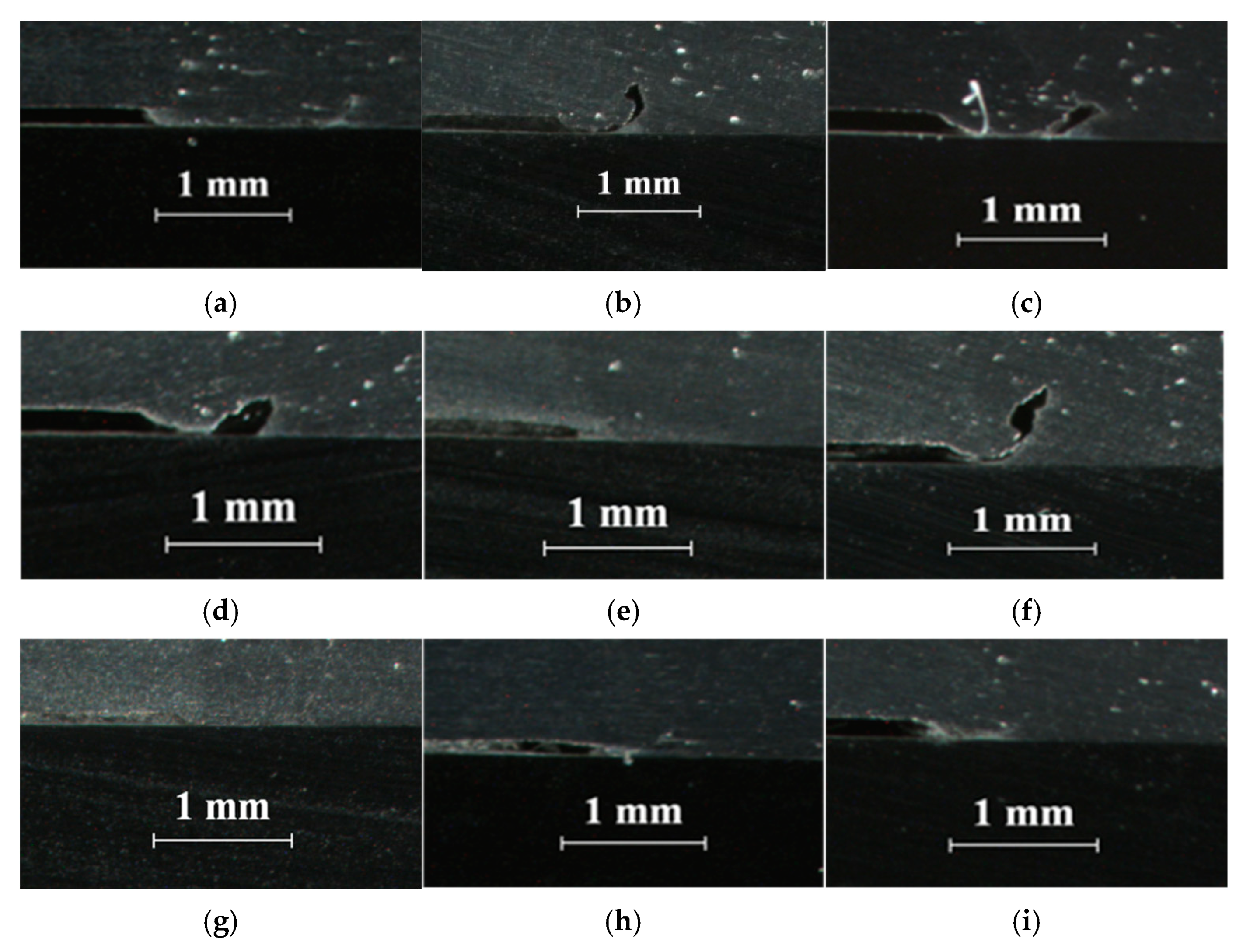
Figure 4.
Comparison of wetting angle and wetting length with different welding currents and EN ratios: (a) wetting angle and (b) wetting length.
Figure 4.
Comparison of wetting angle and wetting length with different welding currents and EN ratios: (a) wetting angle and (b) wetting length.

Figure 5.
Comparison of tensile shear load of dissimilar braze-welded joints with different welding currents with variation in EN ratio.
Figure 5.
Comparison of tensile shear load of dissimilar braze-welded joints with different welding currents with variation in EN ratio.
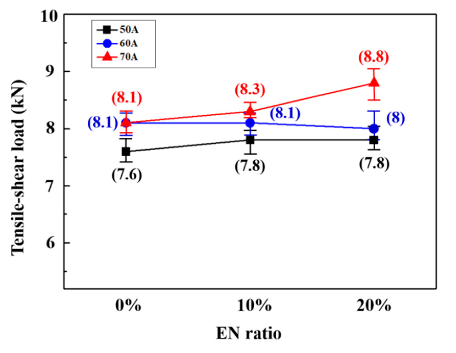
Figure 6.
Typical fractured surface of braze-welded joints after tensile shear test.
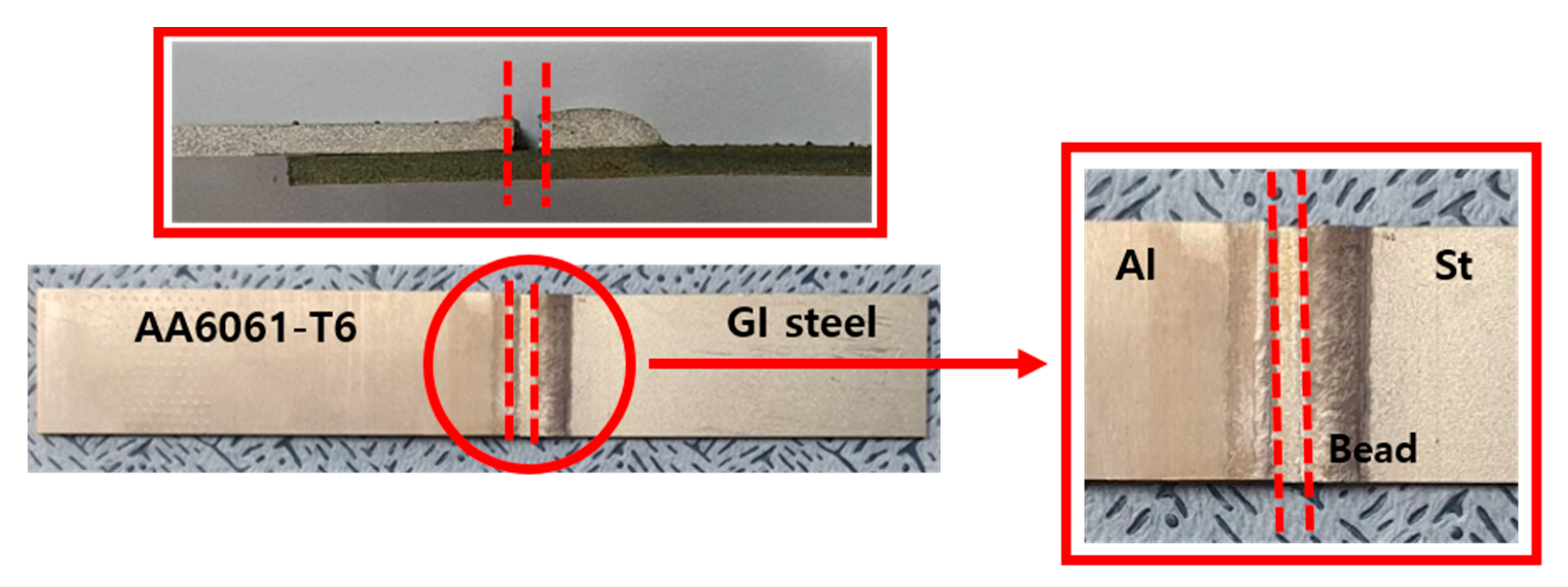
Figure 7.
SEM-EDS spectrum measured in root area: (a) 0%, (b) 10%, (c) 20% and (d) magnified view of (c) on pores.
Figure 7.
SEM-EDS spectrum measured in root area: (a) 0%, (b) 10%, (c) 20% and (d) magnified view of (c) on pores.

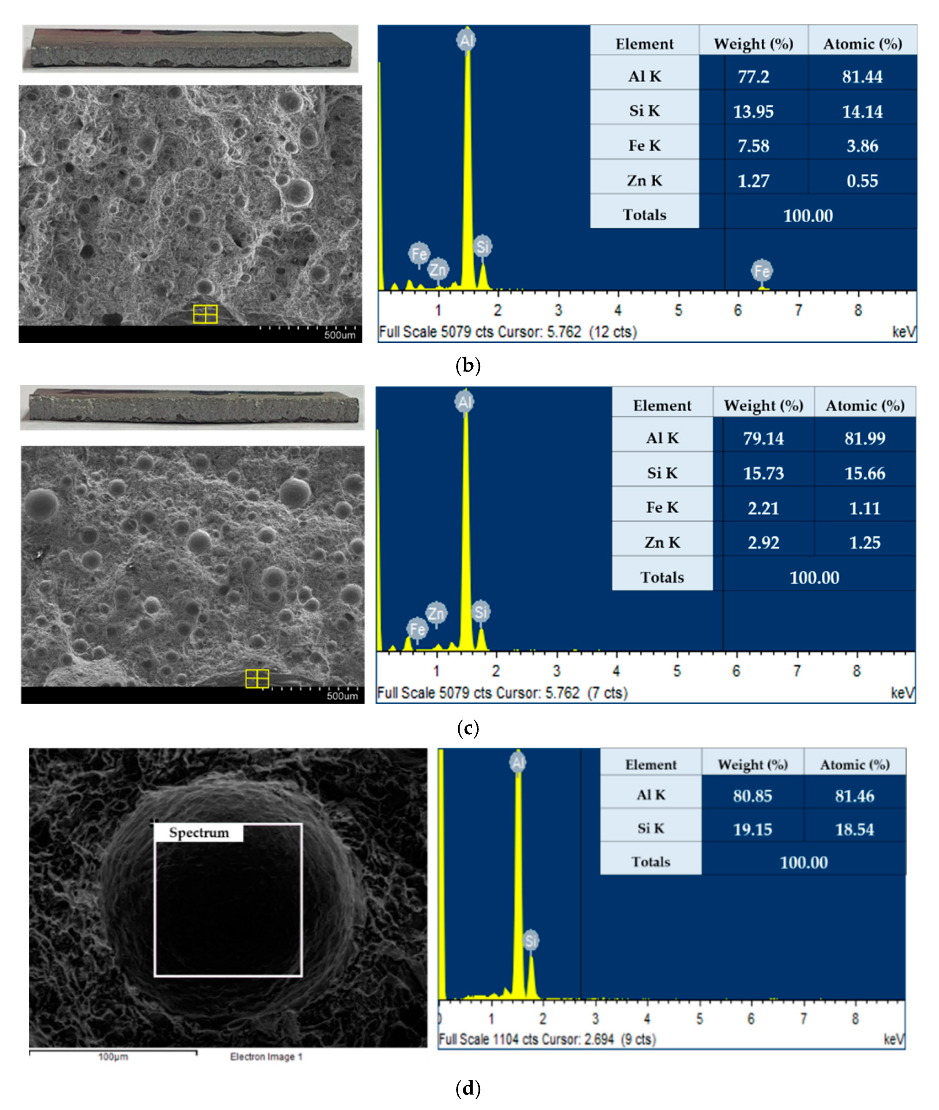
Figure 8.
SEM-EDS results of dissimilar braze-welded joints at joint interface: (a) 0%, (b) 10%, and (c) 20%.
Figure 8.
SEM-EDS results of dissimilar braze-welded joints at joint interface: (a) 0%, (b) 10%, and (c) 20%.

Table 1.
Chemical composition of AA6061-T6, GI steel, and 4047 Al-Si alloy filler wire.
| Materials | Chemical Composition | ||||||||
|---|---|---|---|---|---|---|---|---|---|
| AA6061-T6 | Al | Fe | Si | Mn | Mg | Cu | Zn | Ti | Cr |
| Bal. | 0.7 | 0.4–0.8 | 0.15 | 0.8–1.2 | 0.15–0.4 | 0.25 | 0.15 | 0.04–0.35 | |
| GI steel | Fe | Mn | C | Si | Ti | P | S | ||
| Bal. | 0.18 | 0.032 | 0.02 | 0.001 | 0.014 | 0.005 | |||
| 4047 aluminum wire | Al | Si | Fe | Cu | Mn | Mg | Zn | Be | |
| Bal. | 11–13 | 0.8 | 0.3 | 0.15 | 0.1 | 0.2 | 0.0003 | ||
Table 2.
Mechanical properties of AA6061-T6 and GI steel.
| Metals | Tensile Strength (MPa) | Yield Strength (MPa) | Elongation (%) |
|---|---|---|---|
| AA6061-T6 | 331 | 301 | 10 |
| GI steel | 371 | 282 | 39 |
Table 3.
Welding parameters used for experiments.
| Process Parameter (Unit) | Value |
|---|---|
| Electrode diameter (mm) | 1.2 |
| Welding speed (mm/min) | 500 |
| Work angle/drag angle (degree) | 80/10 |
| Shielding gas | Ar 99.9% |
| Shielding gas flow rate (l/min) | 18 |
| CTWD (mm) | 15 |
| Welding current (A) | 50, 60, 70 |
| Welding voltage (V) | 19 |
| EN ratio (%) | 0, 10, 20 |
| Torch aiming position (mm) | −1, 0, +1, +2 |
Table 4.
Bead appearance and cross-sectional view of braze-welded joints.
| Torch Aiming Position (mm) | Bead Appearance | Cross-Section | Wetting Angle (°) | Wetting Length (mm) |
|---|---|---|---|---|
| −1 | 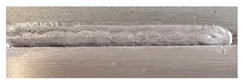 | Not braze-welded | - | - |
| 0 |  |  | 26.5 | 7.6 |
| 1 | 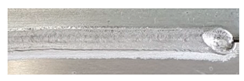 | 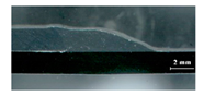 | 21.1 | 7.5 |
| 2 |  | 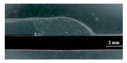 | 45.1 | 7.4 |
Publisher’s Note: MDPI stays neutral with regard to jurisdictional claims in published maps and institutional affiliations. |
© 2021 by the authors. Licensee MDPI, Basel, Switzerland. This article is an open access article distributed under the terms and conditions of the Creative Commons Attribution (CC BY) license (https://creativecommons.org/licenses/by/4.0/).
Share and Cite
MDPI and ACS Style
Ro, C.-S.; Kim, K.-H.; Bang, H.-S.; Yoon, H.-S. Joint Properties of Aluminum Alloy and Galvanized Steel by AC Pulse MIG Braze Welding. Appl. Sci. 2021, 11, 5105. https://doi.org/10.3390/app11115105
AMA Style
Ro C-S, Kim K-H, Bang H-S, Yoon H-S. Joint Properties of Aluminum Alloy and Galvanized Steel by AC Pulse MIG Braze Welding. Applied Sciences. 2021; 11(11):5105. https://doi.org/10.3390/app11115105
Chicago/Turabian StyleRo, Chan-Seung, Kyoung-Hak Kim, Hee-Seon Bang, and Hye-Seul Yoon. 2021. "Joint Properties of Aluminum Alloy and Galvanized Steel by AC Pulse MIG Braze Welding" Applied Sciences 11, no. 11: 5105. https://doi.org/10.3390/app11115105
Note that from the first issue of 2016, this journal uses article numbers instead of page numbers. See further details here.