
Prospects for the Development of High Energy Density Dielectric Capacitors

Institute of Transportation Studies, University of California, Davis, CA 95616, USA
Appl. Sci. 2021, 11(17), 8063; https://doi.org/10.3390/app11178063
Submission received: 21 June 2021
/
Revised: 3 August 2021
/
Accepted: 9 August 2021
/
Published: 31 August 2021
(This article belongs to the Special Issue Supercapacitor Energy Storage Systems: Technology, Performance and Applications)
Abstract
:In this paper, the design of high energy density dielectric capacitors for energy storage in vehicle, industrial, and electric utility applications have been considered in detail. The performance of these devices depends primarily on the dielectric constant and breakdown strength characteristics of the dielectric material used. A review of the literature on composite polymer materials to assess their present dielectric constants and the various approaches being pursued to increase energy density found that there are many papers in which materials having dielectric constants of 20–50 were reported, but only a few showing materials with very high dielectric constants of 500 and greater. The very high dielectric constants were usually achieved with nanoscale metallic or carbon particles embedded in a host polymer and the maximum dielectric constant occurred near the percolation threshold particle loading. In this study, an analytical method to calculate the dielectric constant of composite dielectric polymers with various types of nanoparticles embedded is presented. The method was applied using an Excel spreadsheet to calculate the characteristics of spiral wound battery cells using various composite polymers with embedded particles. The calculated energy densities were strong functions of the size of the particles and thickness of the dielectric layer in the cell. For a 1000 V cell, an energy density of 100–200 Wh/kg was calculated for 3–5 nm particles and 3–5 µ thick dielectric layers. The results of this study indicate that dielectric materials with an effective dielectric constant of 500–1000 are needed to develop dielectric capacitor cells with battery-like energy density. The breakdown strength would be 300–400 V/µ in a reverse sandwich multilayer dielectric arrangement. The leakage current of the cell would be determined from appropriate DC testing. These high energy density dielectric capacitors are very different from electrochemical capacitors that utilize conducting polymers and liquid electrolytes and are constructed much like batteries. The dielectric capacitors have a very high cell voltage and are constructed like conventional ceramic capacitors.
1. Introduction
The most common and simplest electrical energy storage device is the ceramic capacitor that uses a very thin dielectric layer between two metal plates to separate positive and negative charge. The energy stored is proportional to the capacitance C of the dielectric layer and the square of the voltage difference between the metal plates. The capacitance of the dielectric layer depends on its dielectric constant εr, thickness δ, and area A. The capacitance C and energy E stored are given by the following simple formulae.
E = 1/2 CV2, C = ε0 εr A/δ, ε0 = 8.85 × 10⁻¹²
The energy stored per unit area is
E/A = ½ (ε0 εr/δ) V2
The energy density of the capacitor is
Wh/L = 1/2 ε0 εr (V/δ)2
A key material parameter is εr, the effective dielectric constant of the material from which the capacitor is assembled. The energy density of all dielectric capacitor devices is proportional to the voltage squared, but the maximum voltage is limited by the breakdown strength of the dielectric material V/µ. Hence the key material property is εr (V/δ)2. In most cases, attempts to increase the effective dielectric constant have resulted in a significant decrease in breakdown strength. This report is focused on increasing the effective dielectric constant of a polymer composite, but consideration of the breakdown strength of the composite is at least of equal importance.
The general approach discussed in this paper to increase the effective dielectric constant of a polymer composite has its roots in Dr. Burke’s familiarity [1,2,3,4] with electrochemical supercapacitors (ECSCs)—carbon/carbon electric double-layer capacitors (EDLCs) and hybrid ECSCs that utilize microporous carbon and a liquid electrolyte. The charge separation in the electrodes occurs in the double-layer formed in the micro-pores of the carbon at the interface between the liquid electrolyte and the carbon. The capacitance of the electrode is proportional to the specific capacitance (F/g) of the microporous material used to form the electrodes in the cell. In order to increase the energy density of EDLCs (5–10 Wh/kg for a device), hybrid ECSCs have been developed that consist of carbon in one electrode and the second electrode formed from nanoporous carbon coated with metal oxides or conducting polymers that have much higher specific capacitance than the carbon. The charge transport in electrochemical capacitors is due to the diffusion of ions in the electrolyte. The high capacitance of the ECSC is due to the sum of the capacitance of millions of micro-capacitors formed in and around the nano-carbon particles. The dielectric, in this case, is the liquid electrolyte with a rather high dielectric constant (20–80), and the maximum voltage (1–4 V) of the cell depends on the decomposition of the electrolyte. The high capacitance of the cell is due to the distributed charge separation in the double-layer on the surface of the electrically conductive porous carbon and/or its coatings. This charge separation is very much larger (>106) than it could be on the surface of the metal current collector of the cell. The source/sink of the electrical current through the ECSC is by way of the current collector as in a battery. The concept of distributed charge separation and millions of micro-capacitors in a host dielectric can be used as the approach to achieve a high effective dielectric constant in a dielectric cell. ECSC devices are characterized in terms of their capacitance C and resistance R. The charge stored is given by Q = CV and the energy stored is E = 1/2 CVr2, where Vr is the rated voltage of the device. The response time of the ECSC is RC. These are the same relationships given previously to describe the performance of a dielectric capacitor.
Energy storage in a dielectric material is much different than in the electrode of an EC in which there is a physical transport of ions through the liquid electrolyte. In the dielectric material, the material becomes polarized in response to an electric field generated between two electrical conducting surfaces on which surface charge forms. There is no physical movement of atomic material as the dielectric cell is charged and discharged. In the case of the dielectric cells analyzed in this paper, the distance between the conducting surfaces is the spacing of the carbon particles and it is the host dielectric material that is polarized. The maximum electric field possible between the particles depends on the effective breakdown strength characteristics of the host dielectric material. In the dielectric cell, there is no need for a separator because the dielectric material has an extremely low electrical conductivity. It acts as an insulator. In principle, the calculation of performance of the cell is straightforward after its capacitance is known.
This paper consists of several sections. Section 2 is a review of recent research on approaches to achieving significant increases in the dielectric constants of polymer composites for use in energy storage devices. Section 3 is the analytical basis of the present proposed approach for increasing the effective dielectric constant of polymer composites using various embedded elements, including carbon in various forms. Section 4 is the application of the results of Section 3 to the design of high energy density dielectric cells via an Excel spreadsheet model. Section 5 discusses the DC testing of the dielectric cells and the metrics used to describe their performance. Section 6 is a review of selected research on the development of high voltage, film capacitors. Section 7 is a review of recent electrochemical supercapacitor research dealing with carbon, graphene, and polymers to increase the specific capacitance (F/g) of their electrodes. Section 8 is a summary of the paper and important aspects of the development of high energy density dielectric capacitors that make their development uncertain.
2. A Review of the Literature on Energy Storage Using Dielectric Materials
There is extensive literature available dealing with the use of dielectric materials for energy storage. Most of that literature is concerned with increasing the dielectric constant of polymer materials. Most of the research involves the analysis and testing of composite polymers consisting of a host polymer with nano-structured molecular or solid particles dispersed as nano-charge storage elements. Since this is the approach suggested in Section 3 and Section 4 to develop high energy density capacitors, it is appropriate to survey that literature to determine the present state-of-the-art of high dielectric materials using various techniques to increase their dielectric constant. About least 200 papers were surveyed to assess the present state-of-the-art. There are also a number of recent books [5,6,7,8,9] that discuss in detail various aspects of the development and applications of dielectric polymer nanocomposites. Each of the books written in the last ten years treats in detail aspects of polymer nanocomposite technology and its importance in the capacitor industry.
The technical literature is extensive and detailed. It can be divided into the following categories:
- Analytical papers dealing primarily with theory and polymer mixing rules
- Composites of mixtures of different polymers
- Nanocomposites using core-shell coated ceramic particles and metal inserts
- Nanocomposites using Carbons, graphene, and nano-sheets
- Breakdown strength characteristics of polymer composites and films
The literature indicates that many approaches [10,11,12,13,14,15,16,17,18,19,20,21,22,23,24,25,26,27,28,29] have been used to increase the dielectric constant of polymer composites with some success. However, the magnitude of the increase in dielectric constant achieved varied greatly from paper to paper, even for the same approach. Many of the increases achieved were less than a factor of ten which is much less than the goal of at least 500–1000 needed to develop the devices of interest in the present paper. In addition, the increase in dielectric constant is needed at high voltage (>1000 V) with a breakdown strength to sustain that voltage with very small leakage current.
The papers were surveyed to identify studies with large increases in the magnitude of the dielectric constant, very high DC resistance and low loss tangent, and some evidence of high voltage capability. These are difficult requirements to meet, but there were some studies that provided data that indicated they have met some of the target requirements. One of the problems with evaluating the various studies is that the authors do not always specify the dimensions of the elements inserted into the host polymer and the thickness of the material layers being tested. Both factors can have a large influence on the useable dielectric properties of the composites being tested.
2.1. Analytical Papers Dealing Primarily with Theory and Polymer Mixing Rules
The papers [10,11,12,13,14,15] of most interest in this area deal with mixing rules and explanations of why polymer nanocomposites can have high dielectric constants. Key phenomena are the displacement effects (induced electric fields) with high ε ceramic particles and percolation effects with conducting particles. The mixing rules (11, 12) are of most interest as applied to mixing two polymers of different dielectric characteristics.
2.2. Composites of Mixtures of Different Polymers
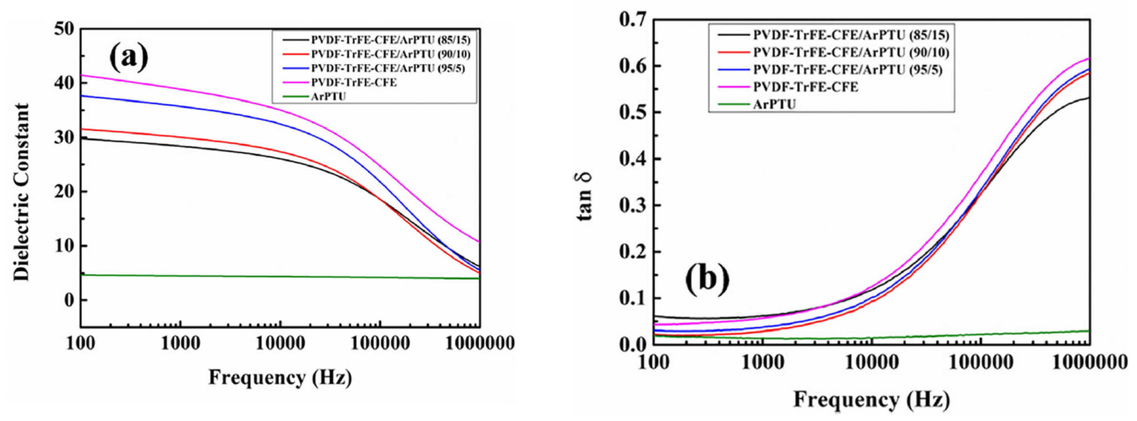
There have been many studies [16,17,18,19] of combining two or more polymers with the objective of attaining a composite with properties more optimum for energy storage. That is a higher dielectric constant, lower loss tangent, and more linear behavior at high voltages. As an example [16], PDVF, which has a high dielectric constant, but relatively high losses and limited voltage linearity, is usually combined with other polymers to obtain a composite polymer with improved loss and voltage linearity than PDVF. Mixing/blending of polymers is not as simple a process as the term would imply as the mixing takes place on a nanoscale with the configuration/spacing of the different polymer molecules being difficult to predict and measure [17,18,19]. Most host polymers are likely to be mixes of several polymers [15,16]. Both of these papers involve the mixing of PVDF with several other polymers to increase the dielectric constant and reduce the conduction losses. Examples of mixing polymers are shown in Figure 1, indicating significant increases in dielectric constant in the composites.
In order to meet the requirements for high dielectric constant, low losses, high voltage, multilayer systems in which the layers have every distinct and different properties and only one of the layers has a high dielectric constant. Reviews of multilayer, high energy density systems are given in [20,21,22]. The multilayer arrangement combines one or two layers having a high dielectric constant with or two layers with very high resistance, high breakdown strength, and relatively low dielectric constant. The layer(s) with very high resistance are intended to block leakage current and increase the effective breakdown voltage of the multilayer system. Research has been done on both the sandwich-type in which the high energy density layer is in the middle with two outside blocking layers and the reverse sandwich-type with the blocking layer in the middle and two high ε layers on the outside. There has been a large variation in the thickness of the layers in the multilayer systems analyzed. The effective dielectric constant of the layered system is less than that of the high ε layers, but the increased breakdown voltage results in an increased energy density of the layered system.
2.3. Percolation Effect
In all the analyses in Section 3, it will be assumed that the particles are uniformly distributed in the host polymer and the charge transfer to the polymer is unimpeded by any surface layer between the particle and the polymer. In other words, the analysis assumes an ideal arrangement that is not likely to occur in practice. Deviations from the ideal are well known from testing of polymer composites and are termed percolation effects [23,24,25,26,27]. Most analyses indicate that the increase in the dielectric constant is linear with the volume loading factor fv. In those cases involving percolation, change in the dielectric constant is very non-linear of the form.
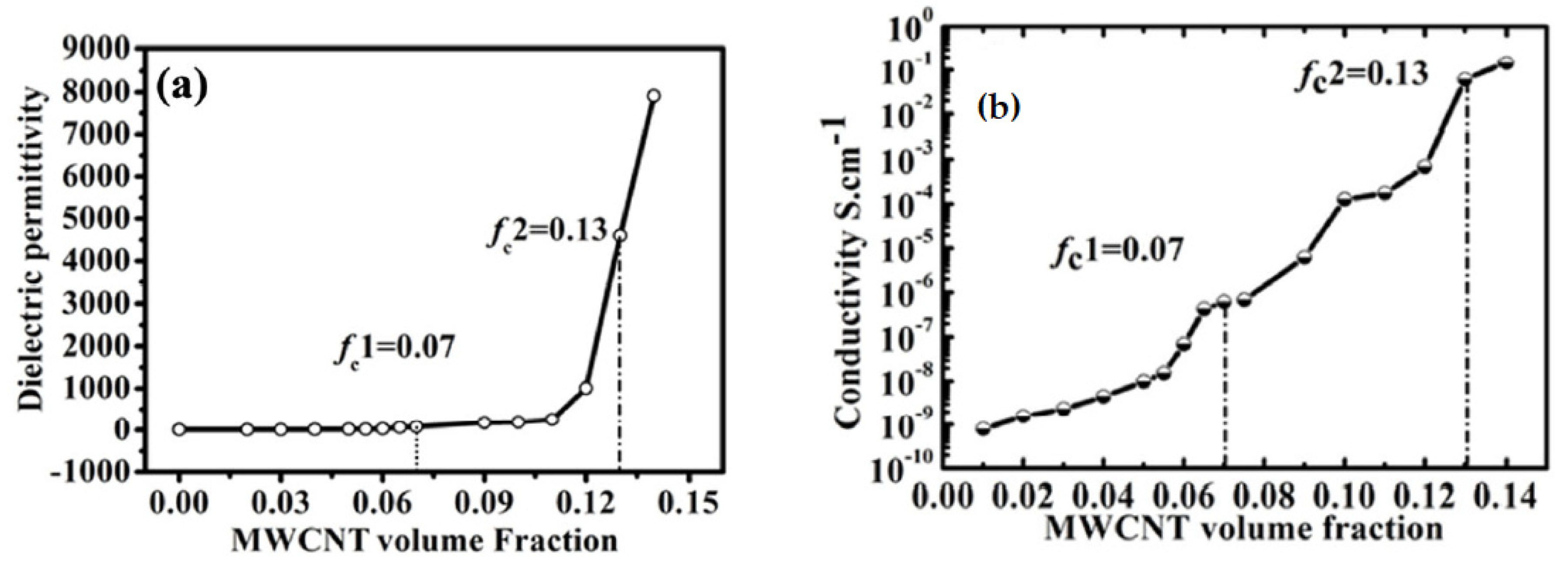
where fvc is the percolation threshold loading and p is the exponent in the percolation effect relationship. The fvc and p values are determined experimentally by varying fv and measuring the effect on ε. Typical experimental data for a polymer composite using carbon nanotubes (MWCNT) are shown in Figure 2. For this test, the threshold value fcv is about 14% and the maximum ε is very high being about 8000. The conductivity of the composite increases over many orders of magnitude as fv is changed, indicating the arrangement of the particles is undergoing large changes. The threshold value can range from a few % to 40–50%, depending on the materials in the device being tested and its thickness. There seems to be a linear zone before the rapid increase of ε in the percolation zone. Incorporating a better understanding of the percolation effects and how to optimize them in developing materials for high energy density dielectric devices will be very important.
ε/εhost = ((fvc − fc)/fc)−p
2.4. Nanocomposites Using Core-Shell Coated Particles and Metal Inserts
There have been many studies of embedding nanocomposites mixing ceramic, ferroelectric particles into a host polymer to attain an increase in dielectric constant [28,29,30,31,32,33,34]. Most of the studies have been done using BaTiO3 particles as they have a very high dielectric constant of 3000–5000. If BaTiO3 particles are deposited in a very thin film (less than 1 µ), the dielectric constant of the film can be 600–800 [25] with a low loss tangent. However, when BaTiO3 particles are mixed into a host polymer, the dielectric constant of the composite [29,30,31] is in the range of 30–40 even at high loadings (30–40%). Higher dielectric constants can be achieved using CCTO particles [29] but with a large percolation effect after 25% loading. Coating the particles and changing their shape can result in modest increases in dielectric constant and a modest percolation effect [33,34], resulting in a dielectric constant of 400–500.
There have been some studies with particles embedded in a host polymer that have resulted in large increases in the dielectric constant. One study [35] used Ni and BaTiO3 particles in PVDF. With only the BaTiO3 particles, the maximum dielectric constant achieved was about 50, but by adding the Ni particles, a dielectric constant of 800 was achieved for a 20% loading of both the BaTiO3 and Ni particles including percolation effects. In another study [36] with PVDF, carbon particles coated with silica were embedded in the host polymer. For a particle loading of about 9%, a dielectric constant of 1000 was achieved with an AC conductivity of 5 × 10⁻⁴ Ohm-cm. These data indicate that embedding conducting particles in the host polymer is a promising approach to achieve large increases in dielectric constant.
2.5. Nanocomposites Using Carbon and Graphene Particles and Nano-Sheets
There have been many studies [37,38,39,40,41] of the application of nano-carbon and graphene in the study of polymer nanocomposites. The carbons in different forms act as conducting elements embedded in the host polymer and thus can act as charge collectors in the micro-capacitors formed throughout the host polymer. The size (µ or nm) of the carbon elements is critical in determining the dielectric constant resulting from their use. Unfortunately, the dimensions of the carbon elements and films used to test the composites are often not given in papers.
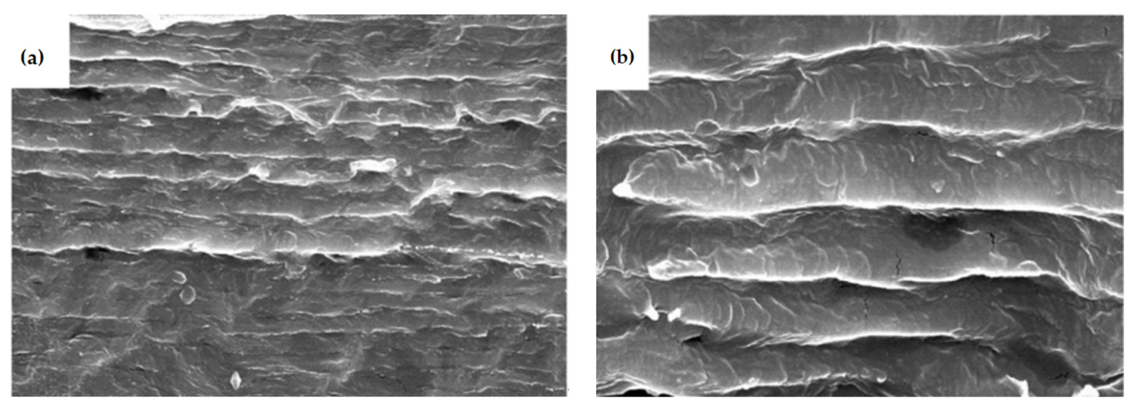
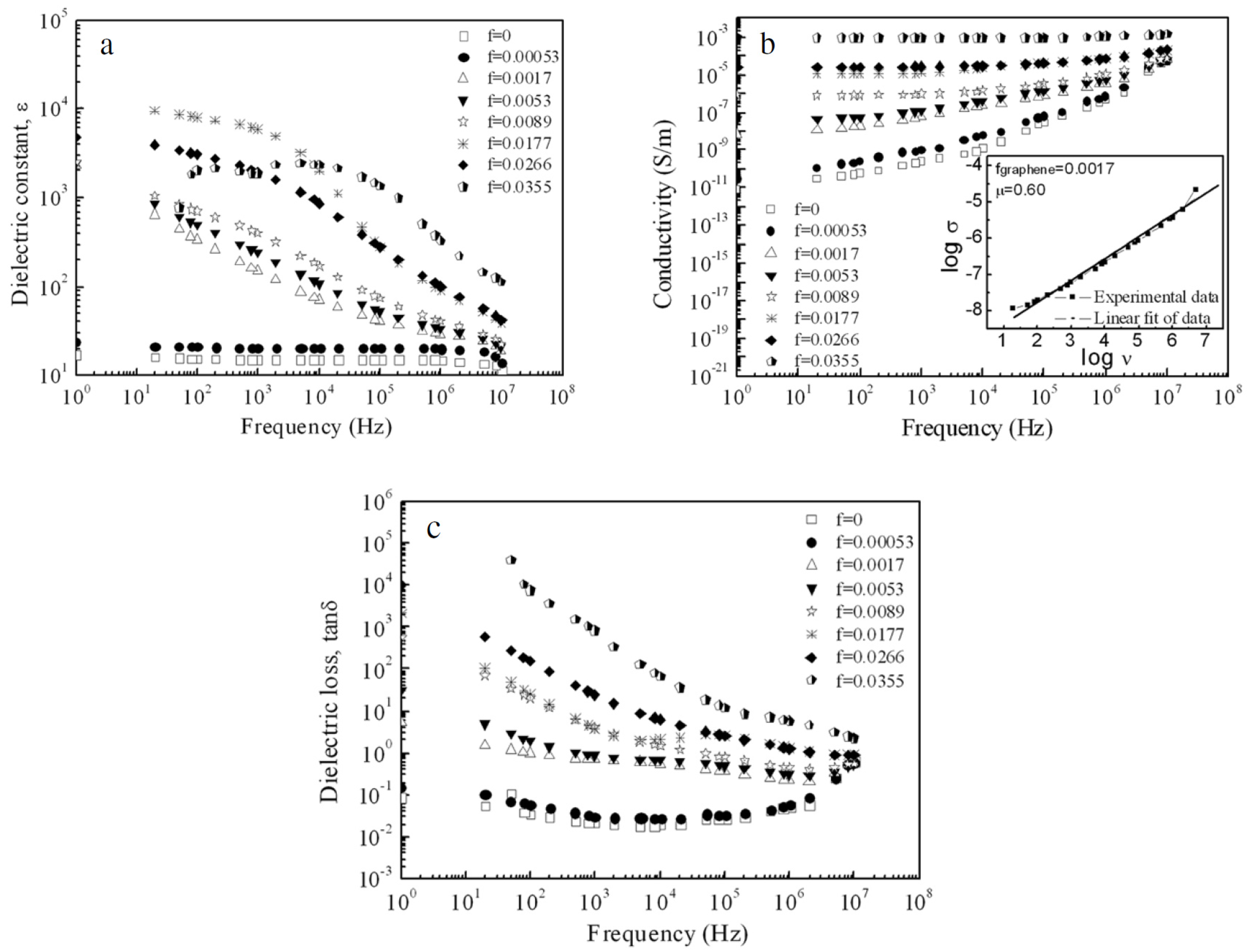
The use of graphene nano-sheets to increase the dielectric constant in composite polymers is of particular interest. The research seems to have been successful in significantly increasing the dielectric constants of composite polymers. It does not seem difficult to produce composites with graphene nano-sheets of a few nm in thickness oriented parallel to a surface. The research in [39,41] is directly related to the approaches analyzed in Section 3 of this report. Ref. [37] dealt with graphene nano-sheets in PVDF. Figure 3 shows 2–6 nm nano-sheets in PVDF as the host polymer at a volume fraction of 0.0177. This volume fraction is low, but the film prepared is thick. From Figure 3, the spacing of graphene sheets is relatively uniform. The polymer composite was hot pressed into disks 9 mm in diameter and 5 mm in thickness. This is a very thick film and is clearly not suitable for a film capacitor. The Excel spreadsheet model in Section 3 predicted a very high effective dielectric constant (over 105) for a 5 mm thickness and 0.018 loading. The measured characteristics of the 5 mm thick disk are shown in Figure 4 taken from [39]. The maximum dielectric constant measured was about 104. The dielectric constant of the host polymer is about 8. Even at a volume fraction loading of 0.0177, both the conductivity and dielectric loss of the film were high. This research [39] was not done to meet energy storage objectives, but it does seem to indicate that the proposed approach of embedding nm carbon elements in a host polymer can make sense as a way to develop high energy density, high voltage film capacitors.
2.6. Breakdown Strength Characteristics of Polymer Composites and Films
The energy stored in a dielectric storage device is given by
where V/δ is the effective breakdown strength(bds) of the device. The unit of bds is MV/m or V/µ. Bds depends on materials in the device and the thicknesses of the dielectric material layers. Bds ranges from 100–400 V/µ or even higher for high quality polymer materials, but bds is usually much lower for composite polymers [42,43,44,45]. Developing composite polymers with high dielectric constant ε and bds values relatively close to that of uniform polymers is key to the use of dielectrics in high energy storage devices. The effect of the bds on the dielectric constant required for 300 V and 800 V cells having energy densities of 100 and 200 Wh/L is shown in Table 1. The cells are film capacitors requiring very thin films, but the dielectric constant of the films seems to be in a reasonable range using the dielectric materials discussed in this paper.
Wh/L = 1/2 ε0 εr (V/δ)2
3. Analysis of Dielectric Cells Using Nanoparticles Embedded in a Host Polymer
The general background for this modeling can be found in [46,47]. The polymer composite capacitor is modeled as an assembly of nm scale micro-capacitors consisting of carbon elements. Uniformly distributed in the host polymer. It is assumed that the carbon elements form a highly regular structure functioning as micro-capacitors that store the electrical charge displaced from the host polymer molecules that are electronically insulating having a dielectric constant ε1. A schematic of the polymer composite structure is shown in Figure 5. The microcaps are shown using both platelet and spherical shaped carbon elements. The characteristic dimensions rp and rh of the spherical and platelet elements are defined in the figure. The elements are of nm scale. The loading of the conducting elements is given in terms of its volume fraction fv. The weight fraction fw can be calculated from the following relation.
fw = fv/(ρ1/ρp (1 − fv) + fv)
Considering the case of the spherical elements, the number Np of elements is given by Np = (VL) fv/(4/3Π rp3), where VL is the volume of the dielectric space. The distance Δ between the centers of the elements is
where L, W, δ are the dimensions of the dielectric space.
L/Δx W/Δ × δ/Δ = Np
Solving for Δ,
Δ = (4/3Π/fv)1/3 rp
The length between the elements δc, which is the separation distance between the electrodes in the microcaps, is given by
δc = Δ − 2rp = k1 rp, where k1 = (4/3Π/fv)1/3 − 2
The capacitance Cc of individual microcaps is given by
where kc is shape factor for the capacitor
Cc = kc ε1ε0Πrp2/δc
ε0 = 8.85 × 10⁻¹² (coul}2/newton-m2
The charge on the microcap is Qc = Cc ΔV = Cc (V/δ) Δ, where V is the voltage across the dielectric space (see Figure 1) assuming V is linear and 2D uniform.
Substituting for Cc,
Qc = (kck2/k1) ε1ε0Πrp2 (V/δ), k2 = (4/3Π/fv)1/3
The total charge displaced in the dielectric space is Qtotal, which is given by
Qtotal = Np Qc = (kck2/k1) ε1ε0 (V/δ) fv (WL)/4/3 rp
For the dielectric cell,
Qtotal = ε2ε0 (A/δ) V
The effective dielectric constant ε2 of the composite dielectric space is
where k1 = (4/3Π)1/3 − 2, k2 = (4/3Π)1/3.
ε2/ε1 = (kck2/4/3k1) fv (δ/rp)
A maximum value for fv = (4/3Π)/8 = 0.52.
The capacitance C2 of the composite polymer capacitor is
and the energy stored E2 is given by
C2 = ε2 ε0 (WL)/δ
E2 = ½ C2 V2
The energy density using spherical carbon elements is (Wh/L) = ½ (ε2 ε0/3600) (V/δ)2 × 10−3 (conversion to L from m3)
Now consider the case of disk-type/platelet elements. In this case the number of elements Nd is given by Nd = (VL) fv/(ld wd δd), where VL is the volume of the dielectric space. lp, wp, and δp are the length, width and thickness of the disk-type element. The spacing of the elements Δd is given by
Δd = (ld wd δd/fv)1/3
The spacing between the element δcd, which is the separation distance between the electrodes in the microcaps, is given by
where k1d = (ld wd/δd2 fv)1/3 − 1
δcd = Δd − δd = k1d δd
The capacitance Ccd of the individual disk-type microcaps is given by
where kcd is the shape factor for the capacitor.
Ccd = kcd ε1ε0 ld wd/δcd
The charge on a microcap is Qcd = Ccd ΔV = Ccd (V/δ) Δd, where V is the voltage across the dielectric space (see Figure 5).
Substituting for Ccd,
Qcd = (kcdk2d/k1d) ε1ε0 ld wd (V/δ), k2d = (ld wd/δd2 fv)1/3
The total charge displaced in the dielectric space is Qtotal, which is given by
Qd total = Nd Qcd = (kcdk2d/k1d) ε1ε0 fw (WL)/δd
The effective dielectric constant ε2 of the composite dielectric space is
where k1d = (ld wd/δd2 fv)1/3 − 1, k2d= (ld wd/δd2 fv)1/3.
ε2/ε1 = (kcdk2d/k1d) fv (δ/δd)
The capacitance C2 of the composite polymer capacitor is
and the energy stored E2 is given by
C2 = ε2 ε0 (WL)/δ
E2 = ½ C2 V2
The energy density for the dielectric cell with platelet elements is
(Wh/L) = ½ (ε2 ε0/3600) (V/δ)2 × 10−3 (conversion to L from m3)
It is of interest to look at the voltage change due to charging the carbon elements and infer the effective resistance of a dielectric cell. The resistivity rcb of carbon is 10−4 to 10−5 ohm-cm. The elements are arranged such that there are δ/∆ elements in series and LW/∆2 in parallel. The resistance of each carbon element is
Relem = rcb rp/∏rp2
The effective resistance of charging the elements is
where Nseries = δ/∆ and Nparallel = LW/∆2, ∆ = (4/3Π/fv)1/rp
Rcharg = Relem Nseries/Nparallel
Rcharg = rcb/∏rp(δ/∆)/(LW/∆2) = rcb/∏ (δ)(4/3Π/fv)1/3)/LW
LW depends on the geometry of the cell. For a spiral wound cell, LW = ∏rcell × heightcell × Nt. Nt is the number turns in winding the cell. For a typical cell, LW = 3.14 × 5 × 15 × 8000 = 1.88 × 10⁵. For δ = 0.0004 cm, fv = 0.2,
Rcharg = 10−4 × 0.32 × 3 × 10−4 × (1.33 × 3.14/0.2)333/1.88 × 105 = 1.4 × 10⁻¹³
Hence the effective resistance due to charging the carbon elements is very small. Note also that the resistance is independent of the particle size.
Next consider the effect of the microcaps on the breakdown characteristics of the composite polymer. The voltage difference across the microcaps is (V/δ) × δc, but the distance between the plates in the microcap is also δc. Since the material between the plates is the host polymer, the breakdown characteristics of the composite should be essentially the same as the host polymer. In addition, the thickness of the potential breakdown layer is very thin, which is a favorable situation.
3.1. Polymer Composites Using High Dielectric Constant Particles
In this section of the paper, the case of a polymer composite using high dielectric constant particles is analyzed. In practice, ceramic particles like BaTiO3 are used. These particles are not conductors, but charge and energy are stored in the particles due to polarization of the molecules in the applied electric field. The same approach as used in the previous analyzes will be used in this analysis.
The first step will be to analysis the response of a spherical particle in the field E0. This a classic problem in electrostatics and the solution is shown in most text books [44]. A key aspect of obtaining the solution is the boundary condition (b.c.) at the interface between the particle and the host polymer. The b.c. is
(D2 − D1). n = 0 at r = rp for dielectrics
D is a vector and is equal εE. Hence
ε2 E2n = ε1 E1n at r = rp, n is the normal component of E
Applying the b.c. to the general solution for the potential function U inside the particle
One finds
U = A2 r cosθ, θ is the angle between r and E0
A2 = −3 E0/(ε2/ε1 + 2), U = −A2 r cosθ
And the electric field E2 inside the particle is constant and in the direction of E0.
E2 = −A2 = 3 E0/(ε2/ε1 + 2), define ef = 3/(ε2/ε1 + 2)
Hence, the electric field inside the particle is greatly reduced.
Now we can analyze the effect of the particles on the effective dielectric constant ε3 of the composite. The capacitance Cp of the particle is given by
Cp = ε2 π rp2
And
Cptot = CpNp = ε2 π rp2 (fv Aδ/4/3πrp3)
The total charge stored by polarization of the particles is
Qtot = Cptot ∆V = ε2 (fv Aδ/4/3rp3)(rpefE0)
The charge of the composite polymer is given by
Qpolym = ε3 A/δ V
Hence ε3/ε2 = 3/8 (3/(ε2/ε1 + 2)) fv δ/rp.
Consider the example: fv = 0.2, δ = 2µ, rp = 2 nm, ε2 = 3000, ε1 = 8, ef = 0.008.
For this case, ε3/ε2 = 0.015 and ε3 = 45.
If the high dielectric constant particles and conducting particles were used to form a polymer composite, the effects of the two types of particles would be multiple. The dielectric constant of the composite is projected to be
εcompos/εhost = (ε3/εhost)(εcondpt/ε3)
3.2. Multilayer Device Analysis
The dielectric devices analyzed consist of three layers. The first device treated has a high ε layer between two lower ε outside layers which have very high resistivity and high breakdown strength. This arrangement is termed the sandwich configuration. The electric fields in the layers are related to their dielectric constants.
where subscript 1 applies to the inner layer and subscript 2 to the outside layers and
ε1E1 = ε2 E2, V0 = 2δ2 E2 + δ1 E1,
E1 = (V0/2δ1) p/(1 + 1/2p), E2 = V0/2δ2/(1 + 1/2p) where p = (δ1/δ2)(ε2/ε1)
∆V1 = V0/2p/(1 + 1/2p), ∆V2 = V0/2/(1 + 1/2p)
The energy stored in the device is
ENt = ½ C1 (∆V1)2 + 2 (½ C2 (∆V2)2)
ENt/(A ε1/δ1)V02 = (1 + 2p)/(8(1 + 1/2p)2)
εdev/ε1 = (δdev/δ1) (1 + 2p)/(4(1 + 1/2p)2)
For the example, consider δ1 = 3 µ, δ2 = 1 µ, ε1 = 60, ε2 = 4, p = 0.20, εdev/ε1 = 0.485, εdev = 29.
Next, the reverse sandwich arrangement will be considered. In this case, the insulating ε2 layer is between two high ε1 layers. In this case,
E1 = (V0/δ1) p/(1 + 2p), E2 = V0/δ2/(1 + 2p) where p = (δ1/δ2)(ε2/ε1)
∆V1 = V0 (p/(1 + 2p)), ∆V2 = V0/(1 + 2p)
ENt/(A ε1/δ1)V02 = p/2/(1 + 2p)
εdev/ε1 = (δdev/δ1) (p/(1 + 2p)2)
For the example, consider δ1 = 5 µ, δ2 = 0.25 µ, ε1 = 60, ε2 = 4, p = 1.33, εdev/ε1 = 0.42, εdev = 25. For both examples of the multilayer device, the problem is the high electric field in the blocking layer.
4. Application of the Analysis to Capacitor Design
The analysis in Section 3 has been applied to prepare an Excel model for the design of dielectric capacitors having specific characteristics. The Excel model permits the rapid calculation of cell characteristics for any inputs of interest. Models were prepared for both spherical and platelet carbon elements. The first step in the model preparation was to calculate the characteristics of a 1 m2 section of the cell for which the characteristics of a spiral wound cell was desired. The second step was to determine the characteristics of a spiral wound cell (Figure 6) of a specific size (diameter and height). The voltage of the cell was an input and, in most cases, was 1000 V. Examples of the model calculations and cell characteristics for both spherical and platelet carbon elements are shown in Table 2. Spiral wound cell characteristic for a range of cell design inputs are shown in Table 3 and Table 4.
The outputs of the Excel models indicate that the spiral wound dielectric cell can have an energy density close to that of lithium batteries if the carbon elements are 1–3 nm and the thickness of the dielectric cell winding is 3–4 µ for a cell voltage of 1000 V. The power of the cell will be very high (MW/L) at very high efficiency (99%). The resistance of the cell will be due mainly to the thin aluminum layers (100 nm) distributing the electrical current to the dielectric winding. The detailed characteristics of two cell designs are shown in Table 2. The performance results shown in Table 3 and Table 4 indicate the energy density is a strong function of the carbon element and cell winding dimensions. The dielectric constant ratio (ε2/ε1) is proportional to δ/rp. The host polymer should have a high dielectric constant (ε1) and breakdown strength (V/µ). Polvinylidene Fluoride (PVDF) seems like a good choice for the host polymer. According to a plastics spec sheet [9], ε1 = 7.5–13.2 and the dielectric strength = 260–950 V/µ. Data for other polymers are given Table 5 taken from [48]. It is clear from Table 5 that selection of a host polymer will involve the trade-off of several performance characteristics (dielectric constant, conductivity, loss tangent, and breakdown strength).
The design results shown in Table 3 and Table 4 indicate that the dielectric capacitors are especially well suited for electric utility applications because of their high cell voltage (1000 V) and very high power capability. They should have long cycle life, low maintenance, and be very safe along with energy densities like batteries. Cost ($/MWh) should be reasonable when produced in high volume when the manufacture of the composite dielectric material with embedded carbon becomes mature.
5. Evaluation/Testing of Dielectric Cells
This paper is concerned with the development of dielectric materials and cells for batteries for vehicles, industrial, and electric utility applications. These applications require the storage of many kWh of energy and power levels of many kWs and system response times of fractions of seconds. In other words, the dielectric devices would be used much like lithium batteries are currently used. Hence testing of dielectric materials and cells should be done using procedures and data interpretation consistent with those applications. Nearly all the testing of dielectric materials and devices in the literature is for power electronics applications and most of the data available were taken over wide ranges of AC frequencies (102–106). Hence the responses of the dielectric devices were measured for response times of ms and shorter.
There has been experience testing electrochemical supercapacitors (EDLCs) that has relevance to testing the dielectric devices (DLCDs) of interest in this paper. The voltage change of both types of devices in charging and discharging is dominated by their capacitance (∆V = ∆Q/C). The energy stored in both types of devices is 1/2 CV2 for ideal, no loss devices. Test procedures and typical data for testing electrochemical supercapacitors are given in [49,50]. That testing is directed to measuring C, R, Wh/L, W/L, and energy efficiencies for ranges of currents and powers. Similar testing will be required of DLCDs.
There are, of course, major differences between EDLCs and DLCDs. First and foremost, the charge in the DLCDs is bound to the layered dielectric material and in the EDLCs, it is free to move through the device. Hence EDLCs have a resistance in the classic sense and DLCDs do not. Most of the losses in the DLDCs are associated with rapid changes in the polarization of the molecules in the dielectric layer as the device is charged and discharged. In addition, EDLCs are low voltage devices with rated (maximum) voltage fixed by the electrolyte. DLCD are high voltage devices with their maximum operating voltage determined by the breakdown strength (MV/m) of the layered dielectric material and its thickness. These differences will influence significantly how DDLCs are tested compared to EDLCs.
There seems to be little discussion of DC testing of DLCDs in the literature. One source is a chapter in [9], which discusses both DC and high frequency testing of DLCDs. The testing should determine the characteristics of both the dielectric layer and the device as a function of current, power, SOC, temperature, and voltage (MV/m). The key parameters to be determined are the dielectric constant of the dielectric layer and the Wh/L, W/L, charge-discharge efficiency, effective parallel resistance, leakage current, and thermal stability of the devices. Varying the thickness of dielectric layer will permit investigation of the effects of high MV/m. Special test equipment will be needed to measure the very low currents expected to be encountered in testing small DLDC cells.
6. Review of Research on High Voltage, Film Capacitors
The analysis and calculations in Section 3 and Section 4 indicate that dielectric cells assembled using a host polymer with nm size carbon elements embedded can have high energy density and very high power. The dielectric layer will be thin (1–5 µ) and the carbon particles must be arranged very uniformly and have very good contact with the host polymer. In other words, the calculated results correspond to an ideal dielectric cell. In addition, the dielectric layers in the devices are very thin films. There are clearly serious questions regarding how closely the ideal assembly of the cells can be approached in practice even after extensive development.
A survey of the literature has not found research using carbon elements in composite polymers to increase their dielectric constant at high voltage (1000 V), but there has been successful research [51,52,53,54] using other types of particles for that purpose in thin films. Also, there has been much research on electrochemical capacitors [52,53,54,55,56] using particulate carbon and graphene sheets/plates to increase the specific capacitance (F/g) of electrodes. In this section, a review of some of the relevant research is presented, and its relevance to the development of the proposed dielectric devices indicated.
Some relevant high voltage research can be found in [51,52,53,54,55]. Ref. [51] is a recent review of the properties of polymer composites used in high voltage applications. It treats many of the same filler particles at high voltage that were considered at lower voltages in Section 2. In [16], a study is described in detail of mixed polymers of various properties to yield a composite with high dielectric constant and high breakdown strength. Thin films of the composite were tested up to 4 kV. The results of the testing are shown in Figure 7, which indicate an energy density of the film of about 6 Wh/L (22 J/cm3) at 370 V/µ. The thickness of the film is not given in [51], but the breakdown value of 4 kV indicates a thickness of 10–15 µ.
Ref. [53] is a good review of the state-of-the-art of thin film plastic capacitors and a discussion of the characteristics of available dielectric polymer materials. The paper is concerned with spiral wound capacitors developed using a new polymer HED (modified polyethylene terephthalate). Test data for the new capacitors are shown in Table 6 and Figure 8. The data indicate an energy density of 1.3 Wh/L (4.7 J/cm3).
Ref. [54] is a presentation by General Electric of the development of a DC bus film capacitor on a DOE contract. That work utilized polyetherimide (PEI) as the polymer dielectric. The film thicknesses were 3–5µ with a breakdown strength of 500–600 V/µ. The results of the development are summarized in Table 7. The energy density of the 800 µF film capacitor shown in the table is 1.5 Wh/L tested at about 1600 V.
Ref. [55] involves the fabrication of spiral wound capacitors from flexible alkali glass (ε = 5.7) ribbons of thickness 50 µ. The capacitance of the device was only 70 nF with energy density of 1.2 Wh/L, but as shown in Figure 9, it was tested to 1000 V with no change in capacitance.
The references cited indicate that thin film devices with thicknesses of 2–4 µ can be fabricated and tested to 1000–2000 V corresponding to breakdown strength of 300–600 V/µ. Using uniform single polymers, the energy densities of the films are only about 1 Wh/L. Using a composite of two different polymers, a thin dielectric film with an energy density of about 6 Wh/L was tested at 370 V/µ.
7. Review of Electrochemical Capacitor Research Using Carbon/Graphene and Polymers
As discussed in previous sections of the paper, the approach taken to increase the dielectric of the composite polymer is to embed nm size spherical particles or nano-sheets/platelets of carbon in the host polymer. Some of the research on using carbons in electrochemical supercapacitors is related to their use in developing polymer composites.
There has been research done to generate spherical carbon particles for use in electrodes for supercapacitors. Since the objective of the supercapacitor research is to prepare carbons with high specific capacitance (F/g), the pore size distribution in the carbon and not the geometric size of particles was of prime interest. As shown in Figure 10, Figure 11 and Figure 12, the particles appear to be nicely spherical, but their diameter is 100–500 nm in most cases [56,57,58]. The smallest diameter carbon spheres found in the literature was 50 nm, which is much larger than needed for the dielectric capacitors. Further work is needed to determine how spherical carbon particles having a diameter of 3–4 nm can be generated.
Over the years, much research has been done to use various forms of carbon to increase the energy density of electric double-layer capacitors (EDLCs). The use of graphene and its derivatives in various forms can significantly increase the specific capacitance of electrode materials [59,60,61,62,63,64]. Nanoscale graphene (particles and atomic scale layers) also enhance electron and thermal conductivity of the electrode, which improves the power capability and capacitance. Skeleton Technology [59] has developed large EDLC devices (3200 F) with an energy density of 8.9 Wh/kg using graphene combined with activated carbon in the electrodes. If used properly, graphene can improve the specific capacitance of carbon electrodes as its theoretical specific capacitance is 550 F/g. El-Kady et al. [60,61] demonstrated cells with very high energy density while maintaining high power density by laser reduction of graphene oxide. Electrochemical capacitor devices with graphene-based electrodes show excellent cycle stability (all-solid-state LSG-EC: >97% after 10000 cycles) in addition to very high energy density and power density. The laser scribed graphene-electrochemical capacitors have high potentiality for commercial applications due to their superior electrode structure. Supercapacitor research [63,64] has also included combining conducting polymers with the nano-carbon to improve the specific capacitance (F/g) of the electrodes. In most cases, the conducting polymers have been used to coat carbon particles, nanotubes, or nanoplatelets.
8. Summary and Conclusions
In this paper, the design of high energy density dielectric capacitors for energy storage in vehicle, industry, and electric utility applications has been considered in detail. The literature on composite polymer materials was reviewed to assess the present state-of-the-art of the dielectric constant of dielectric materials being developed to increase energy density. It was found that there were a number of papers in which dielectric materials having dielectric constants of 20–30 were reported, but only a few showing materials with very high dielectric constants of 500 and greater. The very high dielectric constants were usually achieved with nanoscale metallic or carbon particles embedded in a host polymer and the maximum dielectric constant occurring near the percolation threshold particle loading. Unfortunately, the tangent loss associated with the high dielectric constant was high. In general, the breakdown strength of the composite polymer was significantly less than the host polymer. All the dielectric material testing was done at relatively high frequency and no DC data was available. For some composite polymer materials, the dielectric constant was nearly independent of frequency, but for most materials, the dielectric constant decreased markedly with frequency.
The second step in the study was to develop an analytical method to calculate the dielectric constant of composite polymers with various types of nanoparticles embedded in the host polymer. In the analysis, it was assumed the particles were arranged uniformly and that the effects of the interfaces between the host polymer and the particles were negligible. The analytical results were used in an Excel spreadsheet to calculate the characteristics of spiral wound battery cells using various composite polymers with embedded particles. The calculated energy densities were strong functions of the size of the particles and thickness of the dielectric layer in the cell, but for a 1000 V cell, an energy density of 100–200 Wh/kg was calculated for 3–5 nm particles and 3–5µ thick layers. The analytical method and calculations did not include the effects of percolation and any losses related to changes in molecular polarizability with electric field. Nonetheless, the calculations indicated that the development of dielectric capacitor cells with battery-like energy density may be possible. These devices will be especially useful for electric utility energy storage because of their high cell voltage, long cycle life, and solid-state construction.
The results of this study indicate that dielectric materials with a dielectric constant of 500–1000 are needed to design dielectric capacitor cells with battery-like energy density. These cells would likely use a mix of polymers as the host polymer with nm size carbon and/or graphene particles embedded and a voltage of 800–1000 V. The breakdown strength would be 300–400 MV/m in reverse sandwich multilayer dielectric arrangements. The leakage current of the cell would be determined from appropriate DC testing.
Funding
Work was funded part by consulting with Capacitance Sciences Inc.: Menlo Park, CA, USA, 2005.
Conflicts of Interest
There are no conflict of interest.
Author’ Note
In 2006–2010, a company EEstor in Austin, Texas was claiming to develop a high energy density dielectric capacitor system using sub-micron size Barium Titanate particles in a host polymer that had higher energy density than Lithium batteries. The voltage of the capacitor system was 3500 V. Those claims persist to today (2021) and EEstor has not released any data showing the performance of their cell or produced any product. The EEstor capacitor system is patented and the present situation concerning the EEStor claims are discussed in the Wikipeda-EEStor article available on the internet. Patents as recently as 2019 focus on detailed material preparation and show no performance data for any device. The Austin patents are available on the internet by seeking “Patents for inventor Richard D. Weir” (JUSTIA Patents).
References
- Beard, K.W.; Burke, A.F. (Eds.) Linden’s Handbook of Batteries, 5th ed.; Electrochemical Capacitors; McGraw Hill: New York, NY, USA, 2019; Chapter 20; pp. 953–993. [Google Scholar]
- Burke, A.F.; Zhao, J.Y. Past, Present, and Future of Electrochemical Capacitors: Technology, Performance, and Applications. J. Energy Storage 2021, 35, 10230. [Google Scholar] [CrossRef]
- Zhao, J.Y.; Burke, A.F. Review of supercapacitors: Technologies and Performance Evaluation. J. Energy Chem. 2021, 59, 276–291. [Google Scholar] [CrossRef]
- Zhao, J.Y.; Burke, A.F. Electrochemical Capacitors: Materials, technologies, and performance. Energy Storage Mater. 2021, 36, 31. [Google Scholar] [CrossRef]
- Tanaka, T.; Imal, T. (Eds.) Advanced Nanodielectrics; Pan Stanford: Singapore, 2017. [Google Scholar]
- Nelson, J.K. (Ed.) Dielectric Polymer Nanocomposites; Springer: New York, NY, USA, 2010. [Google Scholar]
- Tjong, S.C. (Ed.) Nanocrystalline Materials; Elsevier: Amsterdam, The Netherlands, 2014. [Google Scholar]
- Ghosh, A.; Dwivedi, M. (Eds.) Processability of Polymetric Composites; Springer: New York, NY, USA, 2020. [Google Scholar]
- Dang, Z.M. (Ed.) Dielectric Polymer Materials for High-Density Energy Storage; Elsevier: Amsterdam, The Netherlands, 2018. [Google Scholar]
- Liu, F.; Li, Q.; Cui, J.; Li, Z.; Yang, G.; Liu, Y.; Dong, L.; Xiong, C.; Wang, H.; Wang, Q. High-Energy-Density Dielectric Polymer Nanocomposites with Trilayered Architecture. Adv. Funct. Mater. 2017, 27, 1606292. [Google Scholar] [CrossRef]
- Prateek; Thakur, V.K.; Gupta, R.K. Recent Progress on Ferroelectric Polymer-Based Nanocomposites for High Energy Density Capacitors: Synthesis, Dielectric Properties, and Future Aspects. Chem. Rev. 2016, 116, 4260–4317. [Google Scholar] [CrossRef] [PubMed]
- Wang, D.; You, F.; Hu, G.H. Graphene/polymer nanocomposites with high dielectric performance: Interface Engineering. Graphene-Based Polym. Nanocompos. Electron. 2015, 1, 49–65. [Google Scholar]
- Mansor, M.R.; Akop, M.Z. Percolation Theory—Comparison between functionalized graphene and carbon nanotubes. Bio-Based Polym. Compos. 2019. [Google Scholar] [CrossRef]
- Ezzat, M.; Sabiha, N.A.; Izzularab, M. Accurate model for computing dielectric onstant of dielectric nanocomposites. Appl. Nanosci. 2014, 4, 331–338. [Google Scholar] [CrossRef] [Green Version]
- Utracki, L.A.; Wilkie, C.A. Polymer Blends Handbook; Springer: New York, NY, USA, 2014. [Google Scholar]
- Li, C.; Shi, L.; Yang, W.; Zhou, Y.; Li, X.; Zhang, C.; Yang, Y. All polymer dielectric films for achieving high energy density fi by blending poly(Vinylidene fluoride-Trifloroethylene-chlorofluoroethylene) with aromatic polythiourea. Nanoscale Res. Lett. 2020, 15, 1–9. [Google Scholar] [CrossRef]
- Qian, K.; Qiao, R.; Chen, S.; Luo, H.; Zhang, D. Enhanced permittivity in polymer blends via tailoring the orderliness of semiconductive liquid crystalline polymers and intermolecular interactions. J. Mater. Chem. C 2020, 8, 8440–8450. [Google Scholar] [CrossRef]
- Zhang, X.; Shen, Y.; Shen, Z.; Jiang, J.; Chen, L.-Q.; Nan, C.-W. Achieving High Energy Density in PVDF-Based Polymer Blends: Suppression of Early Polarization Saturation and Enhancement of Breakdown Strength. ACS Appl. Mater. Interfaces 2016, 8, 27236–27242. [Google Scholar] [CrossRef]
- Chen, Z.; Pei, J.; Li, R. Study of the Preparation and Dielectric Property of PP/SMA/PVDF Blend Material. Appl. Sci. 2017, 7, 389. [Google Scholar] [CrossRef]
- Liu, L.; Qu, J.; Gu, A.; Wang, B. Percolative polymer composites for dielectric capacitors: A brief history, materials, and multilayer interface design. J. Mater. Chem. A 2020, 8, 18515–18537. [Google Scholar] [CrossRef]
- Wang, Y.; Chen, J.; Li, Y.; Niu, Y.; Wang, Q.; Wang, H. Multilayered hierarchical polymer composites for high energy density capacitors. J. Mater. Chem. A 2019, 7, 2965–2980. [Google Scholar] [CrossRef]
- Feng, M.; Zhang, T.; Song, C.; Zhang, C.; Zhang, Y.; Feng, Y.; Chi, Q.; Chen, Q.; Lei, Q. Improved Energy Storage Performance of All-Organic Composite Dielectric via Constructing Sandwich Structure. Polymer 2020, 12, 1972. [Google Scholar] [CrossRef]
- Shehzad, K.; Hakro, A.A.; Zeng, Y.; Yao, S.H.; Xiao-Hong, Y.; Mumtaz, M.; Nadeem, K.; Khisro, N.S.; Dang, Z.M. Two percolation thresholds and remarkably high dielectric permittivity in pristine carbon nanotube/elastomer composites. Appl. Nanosci. 2015, 5, 969–974. [Google Scholar] [CrossRef] [Green Version]
- Wang, W. Novel Metal-Polymer Composite with High Percolation Threshold. M.S. Thesis, Auburn University, Auburn, AL, USA, 6 May 2012. [Google Scholar]
- He, L.; Tjong, S.C. Low percolation threshold of graphene/polymer composites prepared by solvothermal reduction of graphene oxide in the polymer solution. Nanoscale Res. Lett. 2013, 8, 132. [Google Scholar] [CrossRef] [Green Version]
- Zhang, L. Metal-polymer nanocomposites with high percolation threshold andhigh dielectric constant. Curr. Org. Chem. 2013, 17, 2256–2267. [Google Scholar]
- Tu, S.; Jiang, Q.; Zhang, X.; Alshareef, H.N. Large Dielectric Constant Enhancement in MXene Percolative Polymer Composites. ACS Nano 2018, 12, 3369–3377. [Google Scholar] [CrossRef]
- Deshpande, S.B.; Potdar, H.S.; Patil, M.M.; Deshpande, V.V.; Khollam, Y.B. Dielectric properties of BaTiO3 ceramics prepared from powders with bimodal distribution. J. Ind. Eng. Chem. 2006, 12, 584–588. [Google Scholar]
- Fu, J.; Hou, Y.; Zheng, M. Improving dielectric properties of PVDF composites by method. Appl. Mater. Interfaces 2015, 7, 24480–24491. [Google Scholar] [CrossRef]
- Zhang, L.; Shan, X.; Bass, P.; Tong, Y.; Rolin, T.D.; Hill, C.W.; Brewer, J.C.; Tucker, D.S.; Cheng, Z.-Y. Process and Microstructure to Achieve Ultra-high Dielectric Constant in Ceramic-Polymer Composites. Sci. Rep. 2016, 6, 35763. [Google Scholar] [CrossRef] [Green Version]
- Pu, Z.; Tong, L.; Long, Y.; Yang, W.; Huang, X.; Liu, X. Composites of core/shell-structured copper-phthalocyanine-decorated TiO2 particles embedded in poly(arylene ether nitrile) matrix with enhanced dielectric properties. J. Electron. Mater. 2014, 43, 2597–2606. [Google Scholar] [CrossRef]
- Thomas, P.; Dwarakanath, K.; Varma, K.B.R. IN-situ synthesis and characterization of polyaniline-CaCu3TiO12 nano crystal composites. Synth. Met. 2009, 159, 2128–2134. [Google Scholar] [CrossRef] [Green Version]
- He, F.; Ren, W.; Liang, G.; Shi, P.; Wu, X.; Chen, X. Structure and dielectric properties of barium titanate thin films for capacitor applications. Ceram. Int. 2013, 39, S481–S485. [Google Scholar] [CrossRef]
- Kim, D.S.; Baek, C.; Ma, H.J.; Kim, D.K. Enhanced dielectric permittivity of BaTiO3/epoxy resin composites by particle alignment. Ceram. Int. 2016, 42, 7141–7147. [Google Scholar] [CrossRef]
- Zang, Z.M.; Shen, Y.; Nan, C.W. Dielectric behavior of three-phase percolative Ni-BaTiO3/polyvinylidene fluoride composites. Appl. Physis Lett. 2002, 81, 4814. [Google Scholar]
- Lei, T.; Xue, Q.; Chu, L.; Han, Z.; Sun, J.; Xia, F.; Zhang, Z.; Guo, Q. Excellent dielectric properties of polymer composites based on core-shell structured carbon/silica nanohybrid. Appl. Phys. Lett. 2013, 103, 012902. [Google Scholar] [CrossRef]
- Arthisree, D.; Joshi, G.M. Graphene oxide derived high dielectric constant of polymer blends. Mater. Res. Express 2018, 5, 075304. [Google Scholar] [CrossRef]
- Fan, P.; Wang, L.; Yang, J.; Chen, F.; Zhong, M. Graphene/poly(vinylidene fluoride) composites with high dielectric constant and low percolation threshold. Nanotechnology 2012, 23, 365702. [Google Scholar] [CrossRef]
- Meng, Q.; Jin, J.; Wang, R.; Kuan, H.C.; Ma, J.; Kawashima, N.; Michelmore, A.; Zhu, S.; Wang, C.H. Processable 3-nm thick graphene platelets of high conductivity and their epoxy composites. Nanotechnology 2014, 25, 125707. [Google Scholar] [CrossRef] [PubMed]
- Yang, K.; Huang, X.; Fang, L.; He, J.; Jiang, P. Fluoro-polymer functionalized graphene for flexible ferroelectric polymer-based high-k nanocomposites with suppressed dielectric loss and low percolation threshold. Nanoscale 2014, 6, 14740–14753. [Google Scholar] [CrossRef] [PubMed]
- Yousefi, N.; Sun, X.; Lin, X.; Shen, X.; Jia, J.; Zhang, B.; Tang, B.; Chan, M.; Kim, J.-K. Highly Aligned Graphene/Polymer Nanocomposites with Excellent Dielectric Properties for High-Performance Electromagnetic Interference Shielding. Adv. Mater. 2014, 26, 5480–5487. [Google Scholar] [CrossRef] [PubMed]
- Grabowski, C.A.; Fillery, S.P.; Westing, N.M.; Chi, C.; Meth, J.S.; Durstock, M.F.; Vaia, R.A. Dielectric breakdown in silica-amorphous polymer composite films: The role of the polymer matrix. Appl. Mater. Interfaces 2013, 5, 5486–5492. [Google Scholar] [CrossRef] [PubMed]
- Beier, C.W.; Sanders, J.M.; Brutchey, R.L. Improved Breakdown Strength and Energy Density in Thin-Film Polyimide Nanocomposites with Small Barium Strontium Titanate Nanocrystal Fillers. J. Phys. Chem. C 2013, 117, 6958–6965. [Google Scholar] [CrossRef]
- Fillery, S.P.; Koerner, H.; Drummy, L.; Dunkerley, E.; Durstock, M.F.; Schmidt, D.; Vaia, R.A. Nanolaminates: Increasing Dielectric Breakdown Strength of Composites. ACS Appl. Mater. Interfaces 2012, 4, 1388–1396. [Google Scholar] [CrossRef]
- Xia, X.; Xu, B.X.; Xiao, X.; Weng, G.J. Modeling the dielectric breakdown strength and energy storage density of graphite-polymer composites with dielectric damage process. Mater. Des. 2020, 189, 108531. [Google Scholar] [CrossRef]
- Burke, A.F. Analysis of Single and Multiple Layered Approaches to the Design of Dielectric Material Supercapacitors for Vehicle Applications; Capacitance Sciences Inc.: Menlo Park, CA, USA, 2005. [Google Scholar]
- Reitz, J.R.; Milford, F.J. Foundations of Electromagnetic Theory; Addison-Wesley Publishing Company: Massachusetts, MA, USA, 1961. [Google Scholar]
- Omnexus Dielectric Product Sheet. Available online: https://omnexus.specialchem.com/polymer-properties/properties/dielectric-constant (accessed on 8 August 2021).
- Zhao, J.; Gao, Y.; Burke, A.F. Performance testing of supercapacitors: Important issues and uncertainties. J. Power Sources 2017, 363, 327–340. [Google Scholar] [CrossRef]
- Burke, A.; Miller, M. The power capability of ultracapacitors and lithium batteries for electric and hybrid vehicle applications. J. Power Sources 2011, 196, 514–522. [Google Scholar] [CrossRef]
- Pleşa, I.; Noţingher, P.V.; Schlögl, S.; Sumereder, C.; Muhr, M. Properties of Polymer Composites Used in High-Voltage Applications. Polymers 2016, 8, 173. [Google Scholar] [CrossRef]
- Li, B.; Galan, F.S.; Xidas, P.I.; Manias, E. Improving Electrical breakdown strength of polymer nanocomposites by tailoring hybrid-filler structure for high voltage dielectric applications. Appl. Nano Mater. 2018, 1, 4401–4407. [Google Scholar] [CrossRef]
- Winsor, P.; Lobo, E.; Zafar, M.; Munshi, A.; Ibrahim, A. New Polymer Dielectric for High. Energy Density Film Capacitors; CDE: New Bedford, MA, USA.
- Flanagan, K.; Graziano, M. High Performance DC Bus Film Capacitor, Presentation; GE Global Research: Niskayuna, NY, USA, 2014. [Google Scholar]
- Wilke, R.; Baker, A.; Hettler, C.; Raegan, J.-W.; Chad, H. Fabrication of wound capacitors using flexible alkali-free glass. IEEE Trans. Compon. Packag. Manuf. Technol. 2016, 6, 1555–1560. [Google Scholar] [CrossRef]
- Kisakibaru, Y.; Nandiyanto, A.D.; Balgis, R.; Ogi, T.; Okuyama, K. Preparation of porous carbon particles using a spray-drying method with colloidal template. Int. J. Chem. Biol. Eng. 2012, 6, 29–32. [Google Scholar]
- Okazaki, S.; Hamai, K.; Arif, A.F.; Ogi, T.; Okuyama, K. Facile synthesis of spherical carbon composite particles via a dry granulation process. Carbon 2015, 94, 439–447. [Google Scholar] [CrossRef]
- Sedira, S.; Mendai, B. Hydrothermal synthesis of spherical carbon nanoparticles (CNPs) for supercapacitor electrode uses. Mater. Renew. Sustain. Energy 2020, 9, 1–9. [Google Scholar] [CrossRef] [Green Version]
- Du, X.; Guo, P.; Song, H.; Chen, X. Graphene nanosheets as electrode material for electric double-layer capacitors. Electrochim. Acta 2010, 55, 4812–4819. [Google Scholar] [CrossRef]
- El-Kady, M.F.; Strong, V.; Dubin, S.; Kaner, R.B. Laser scribing of high-performance and flexible graphene-based electrochemical capacitors. Science 2012, 335, 1326–1330. [Google Scholar] [CrossRef] [Green Version]
- El-Kady, M.F.; Kaner, R.B. Scalable fabrication of high-power graphene micro-supercapacitors for flexible and on-chip energy storage. Nat. Commun. 2013, 4, 1475. [Google Scholar] [CrossRef]
- Wang, S.; Ma, L.; Gan, M.; Fu, S.; Dai, W.; Zhou, T.; Wang, H. Free-standing 3D graphene/polyaniline composite film electrodes for high-performance supercapacitors. J. Power Sources 2015, 299, 347–355. [Google Scholar] [CrossRef]
- Xu, R.; Guo, F.; Cui, X.; Zhang, L.; Wang, K.; Wei, J. High performance carbon nanotube based fiber-shaped supercapacitors using redox additives of polypyrrole and hydroquinone. J. Mater. Chem. A 2015, 3, 22353–22360. [Google Scholar] [CrossRef]
- Meng, Q.; Cai, K.; Chen, Y.; Chen, L. Research progress on conducting polymer based supercapacitor electrode materials. Nano Energy 2017, 36, 268–285. [Google Scholar] [CrossRef]
Figure 1.
Dielectric constant data for polymer mixes involving PVDF [16]. (a) Dielectric constant of ArPTU, PVDF-TrFE-CFE, and PVDFTrFE-CFE/ArPTU composite films; (b) Dielectric loss of ArPTU, PVDFTrFE-CFE, and PVDF-TrFE-CFE/ArPTU composite films.
Figure 1.
Dielectric constant data for polymer mixes involving PVDF [16]. (a) Dielectric constant of ArPTU, PVDF-TrFE-CFE, and PVDFTrFE-CFE/ArPTU composite films; (b) Dielectric loss of ArPTU, PVDFTrFE-CFE, and PVDF-TrFE-CFE/ArPTU composite films.

Figure 2.
The percolation effect on the dielectric constant [23].(a) Dielectric Permittivity; (b) electricalconductivity of CNT/elastomer composites as a function of CNT loadings.
Figure 2.
The percolation effect on the dielectric constant [23].(a) Dielectric Permittivity; (b) electricalconductivity of CNT/elastomer composites as a function of CNT loadings.

Figure 3.
SEM micrographs of the graphene/PVDF composite containing graphene volume fractions of 0.0177 (a,b) [38].
Figure 3.
SEM micrographs of the graphene/PVDF composite containing graphene volume fractions of 0.0177 (a,b) [38].

Figure 4.
Dependences of (a) dielectric constants, (b) ac conductivities and (c) loss tangent on frequency for the graphene/PVDF composites at room temperature [38].
Figure 4.
Dependences of (a) dielectric constants, (b) ac conductivities and (c) loss tangent on frequency for the graphene/PVDF composites at room temperature [38].

Figure 5.
Geometric configurations of the microcaps.

Figure 6.
Schematic of a spiral wound d dielectric cell.

Figure 7.
Energy density and breakdown data for mixed- polymer thin films. (a) The energy density of PVDF-TrFE-CFE/ArPTU composite films with different composite ratios; (b) Comparing of discharge energy density of our works with reported works [16].
Figure 7.
Energy density and breakdown data for mixed- polymer thin films. (a) The energy density of PVDF-TrFE-CFE/ArPTU composite films with different composite ratios; (b) Comparing of discharge energy density of our works with reported works [16].

Figure 8.
Breakdown data for thin 2-3 µ polymer films [53].
Figure 8.
Breakdown data for thin 2-3 µ polymer films [53].

Figure 9.
A spiral wound film capacitor tested at 1000 V [55].
Figure 9.
A spiral wound film capacitor tested at 1000 V [55].

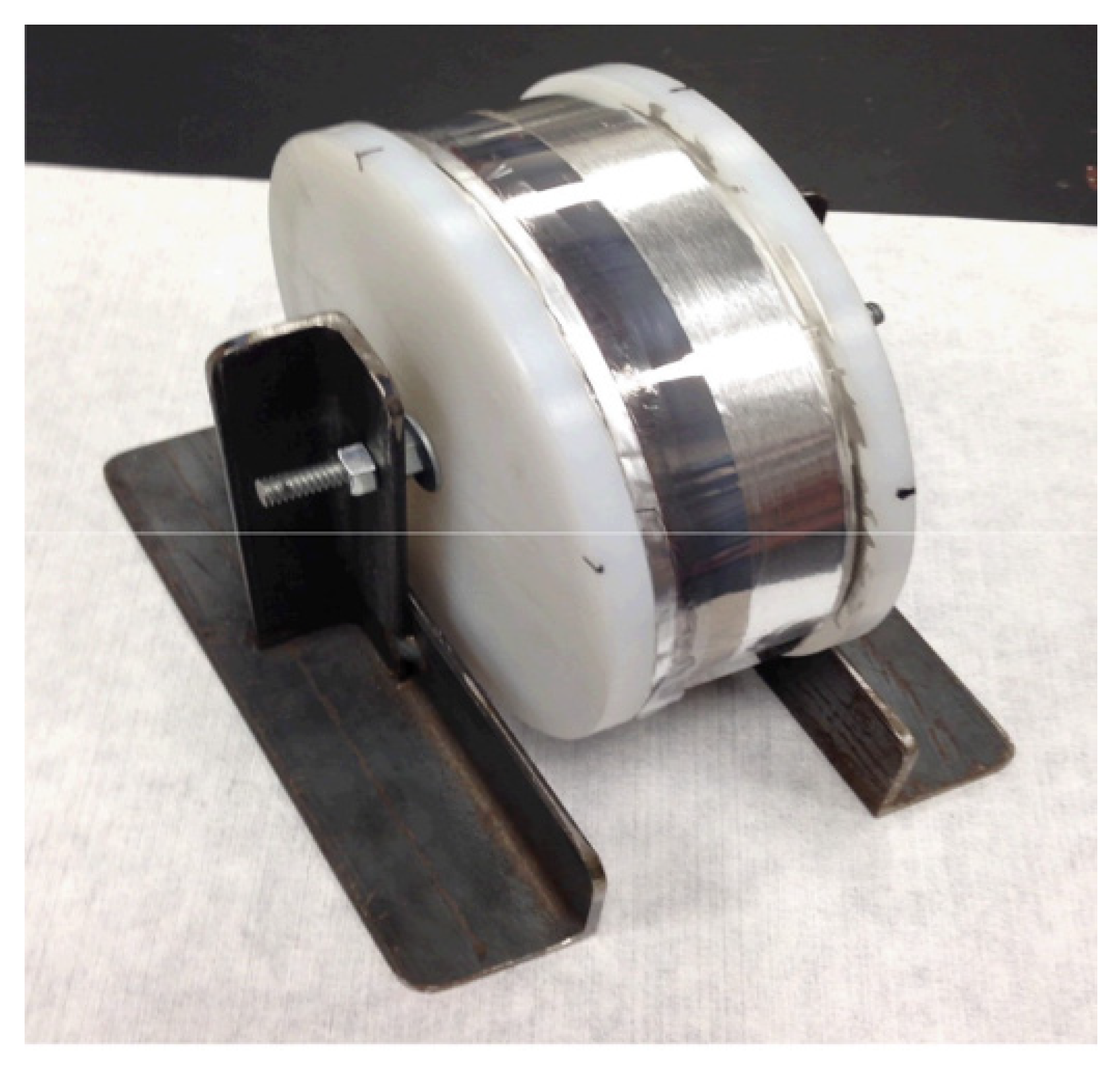
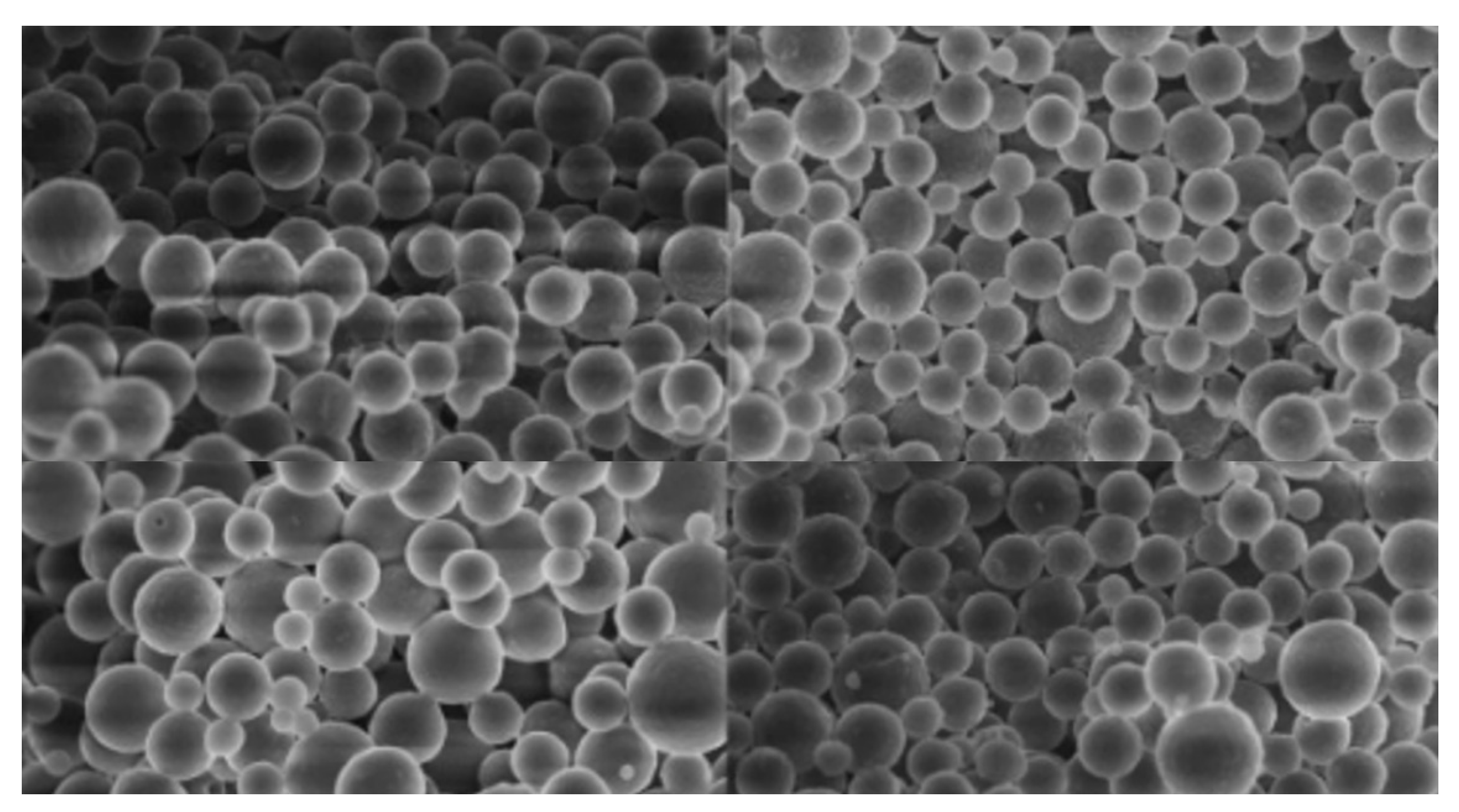
Figure 10.
Spherical carbon particles.

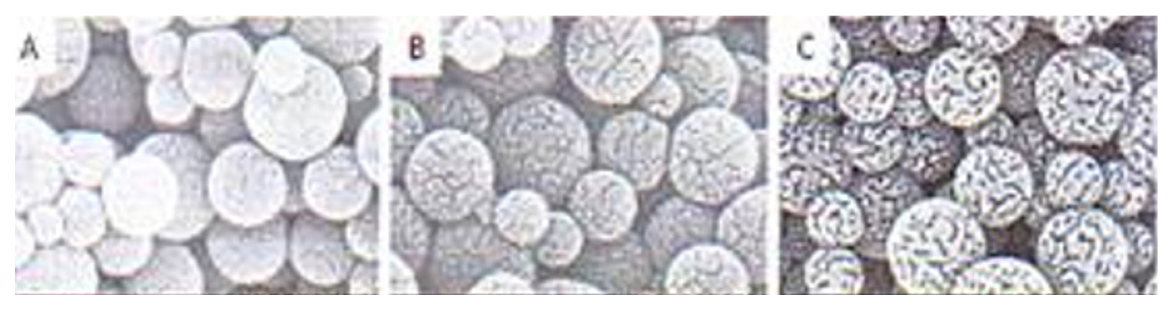
Figure 11.
Porous spherical carbon particles for supercapacitor electrodes. Representative electron micrographs showing (A) Pristine carbon nanospheres prepared by HTS; (B) Carbon spheres after carbonization; (C) Carbon spheres after graphitization.
Figure 11.
Porous spherical carbon particles for supercapacitor electrodes. Representative electron micrographs showing (A) Pristine carbon nanospheres prepared by HTS; (B) Carbon spheres after carbonization; (C) Carbon spheres after graphitization.

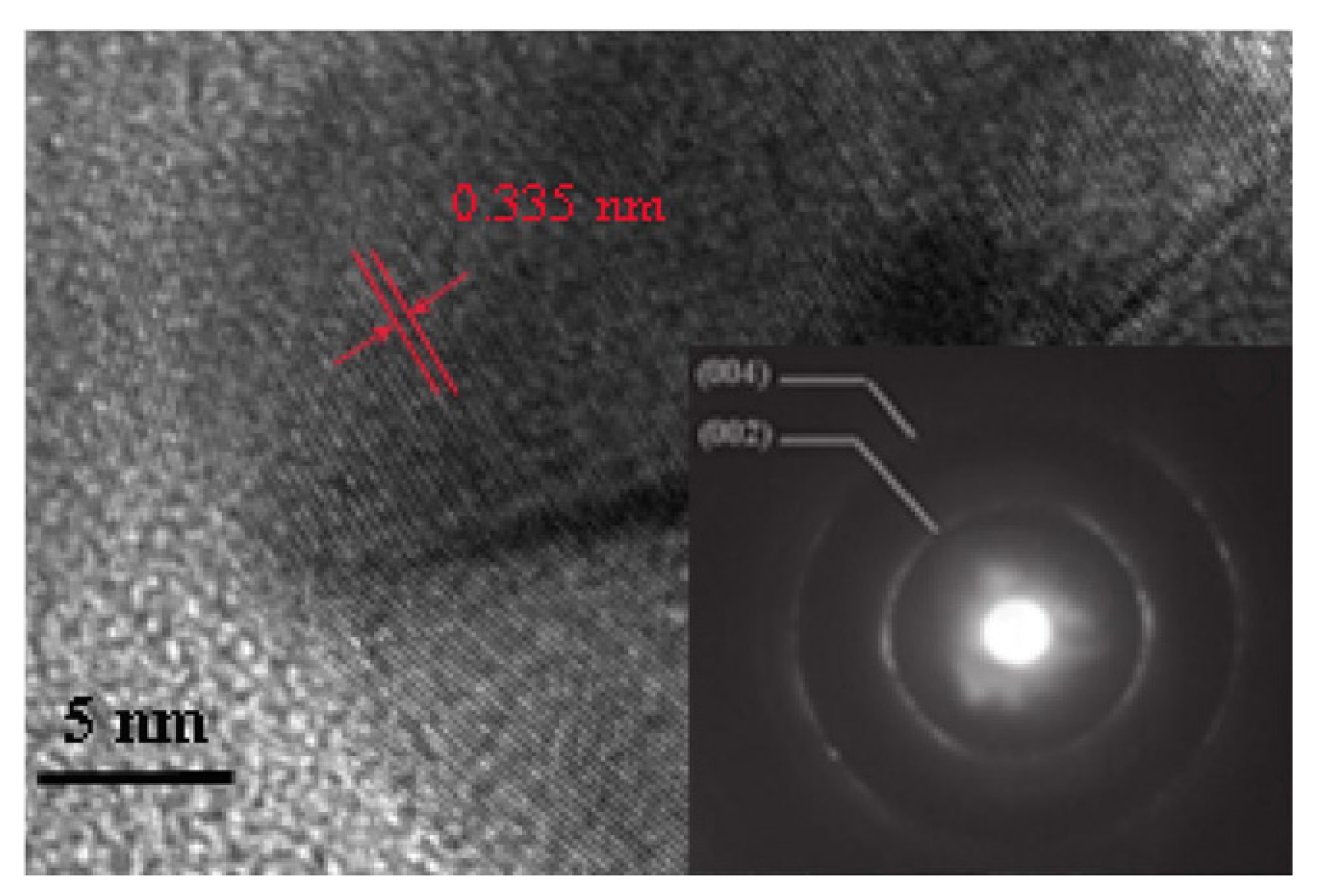
Figure 12.
High-resolution transmission electron microscopy (HRTEM) measurement of a spherical carbon particle [58].
Figure 12.
High-resolution transmission electron microscopy (HRTEM) measurement of a spherical carbon particle [58].


Table 1.
The effect of breakdown strength on the required dielectric constant for cells of high energy density.
Table 1.
The effect of breakdown strength on the required dielectric constant for cells of high energy density.
| Dielectric Cell Wh/L | Breakdown Strength V/µ | Cell Voltage | Dielectric Constant Needed | Dielectric Film Thickness µ |
|---|---|---|---|---|
| 200 | 400 | 300 | 1020 | 0.75 |
| 800 | 1020 | 2.0 | ||
| 100 | 400 | 300 | 510 | 0.75 |
| 800 | 510 | 2.0 | ||
| 200 | 250 | 300 | 2610 | 1.2 |
| 800 | 2610 | 3.2 | ||
| 100 | 250 | 300 | 1305 | 1.2 |
| 800 | 1305 | 3.2 |
Table 2.
Spreadsheet design results for spiral wound cells.
| Elements. | Spherical | Platelets |
|---|---|---|
| Volume frac. | 0.2 | 50 nm square |
| dimensions | Radius 3 nm | Thickness 1 nm |
| Host polymer ε1 | 8 | 8 |
| Cell | ||
| ε2/ε1 ε ratio | 735 | 628 |
| Diameter, height, cm | 8, 16 | 8, 16 |
| Madrel radius cm | 1.25 | 1.25 |
| thickness µ | 4 | 3 |
| Number of turns | 7211 | 9171 |
| Average radius cm | 2.3 | 2.3 |
| Total area m2 | 167 | 213 |
| Voltag V | 1000 | 1000 |
| Capacitance F | 2.2 | 3.15 |
| Wh | 227 | 328 |
| Wh/L | 282 | 409 |
| Total weight kg | 1.275 | 1.28 |
| Wh/kg | 178 | 256 |
| Breakdown V/µ | 250 | 333 |
| Resistance mOhm | 4.2 | 3.3 |
| Max. Power 99% eff. kW | 1314 | 1672 |
| kW/L 99% eff. | 1030 | 1305 |
| kW/kg 99% eff. | 1635 | 2080 |
Table 3.
Dielectric cell Wh/L using spherical carbon elements and host polymer.
| Vol. Frac. fv = 0.2 | Host Polymer Єr = 4 | Host Polymer Єr = 8 | ||
|---|---|---|---|---|
| Voltage | Dielectric Thick break µ down……V/µ | Element radius nm | Cell Wh/kg | Cell Wh/kg |
| 1000 | 5 200 | 3 | 135 | 271 |
| 5 | 81 | 162 | ||
| 10 | 40 | 80 | ||
| 10 100 | 3 | 67 | 135 | |
| 5 | 41 | 82 | ||
| 10 | 20 | 40 | ||
| 15 66 | 3 | 45 | 90 | |
| 5 | 27 | 54 | ||
| 10 | 13 | 27 | ||
| 500 | 5 100 | 3 | 34 | 68 |
| 5 | 20 | 40 | ||
| 10 | 10 | 20 | ||
| 10 50 | 3 | 17 | 34 | |
| 5 | 10 | 20 | ||
| 10 | 5 | 10 | ||
| 15 33 | 3 | 11 | 22 | |
| 5 | 7 | 14 | ||
| 10 | 3.5 | 7 |
Table 4.
Dielectric cell Wh/L using platelet graphene carbon elements and host polymer.
| Vol. Frac. fv = 0.2 | Host Polymer Єr = 4 | Host Polymer Єr = 8 | ||
|---|---|---|---|---|
| Voltage | Dielectric Thick Break down µ V/µ | Platelet thickness nm | Cell Wh/kg | Cell Wh/kg |
| 1000 | 5 200 | 2 | 79 | 158 |
| 4 | 41 | 82 | ||
| 6 | 29 | 58 | ||
| 10 100 | 2 | 40 | 80 | |
| 4 | 21 | 42 | ||
| 6 | 14 | 28 | ||
| 15 66 | 2 | 26 | 52 | |
| 4 | 14 | 28 | ||
| 6 | 9 | 18 | ||
| 500 | 5 100 | 2 | 20 | 40 |
| 4 | 10 | 20 | ||
| 6 | 7 | 14 | ||
| 10 50 | 2 | 10 | 20 | |
| 4 | 5 | 10 | ||
| 6 | 3.6 | 7.2 | ||
| 15 33 | 2 | 6.6 | 13.2 | |
| 4 | 3.5 | 7 | ||
| 6 | 2.4 | 4.8 |
Table 5.
Characteristics of possible host polymers [48].
Table 5.
Characteristics of possible host polymers [48].
| Capacitor Types | K | Dielectric Strength (V/mm) | DF (%) | Volume Resistivity (Ohms.cm) | Max. Oper. Temp (°C) | Energy Density (J/cc) Intrinsic Practical | Energy Density % of Intrinsic | |
|---|---|---|---|---|---|---|---|---|
| Plastic Film | ||||||||
| Polycarbonate (PC) | 2.8 | 350 | <1 | 2 × 10¹⁷ | 150 | 3.6 | 0.5–1 | 28 |
| Polypropylene (PP) | 2.2 | 500 | <0.1 | 1 × 10¹⁸ | 105 | 4.1 | 1–1.5 | 36 |
| Polyester (PET) | 3.3 | 400 | <1.5 | 1 × 10¹⁷ | 125 | 4.9 | 1–1.5 | 30 |
| Polyvinylidenefluoride (PVDF) | 12 | 200 | 1–5 | 1 × 10¹⁵ | 105 | 19.1 | 2.4 | 12 |
| Polyethylenenapthalate (PEN) | 3.2 | 440 | <1 | 1 × 10¹⁷ | 137 | 4.4 | 1–1.5 | 34 |
| Polyphenylenesulfide (PPS) | 3.0 | 360 | <0.2 | 5 × 10¹⁷ | 200 | 4.1 | 1–1.5 | 36 |
Table 6.
Characteristics of the HED film capacitors [53].
Table 6.
Characteristics of the HED film capacitors [53].
| “3 mm” Control Mylar® PET(WO 279132) | “3 mm” Control Mylar® PET(WO 279133) | |
| Avg.Capacitance, DF (120 Hz) | 63 mF, 0.6% | 70 mF, 0.7% |
| Active Length | 9492 cm | 8710 cm |
| Thickness | 3.35 micron | 2.80 micron |
| “4 mm” control Mylar® PET(WO 279277) | “4 mm” control Mylar® PET(WO 279279) | |
| Avg.Capacitance | 40 mF, 0.6% | 39 mF, 0.6% |
| Active Length | 6137 cm | 6017 cm |
| Thickness | 3.53 micron | 4.24 micron |
Table 7.
Summary of the characteristics of the film capacitor being developed by General Electric [51].
Table 7.
Summary of the characteristics of the film capacitor being developed by General Electric [51].
| 800 µF Capacitor | 3 µm PEI | 2.5 µm PP |
|---|---|---|
| Film volume (L) | 0.254 | 0.257 |
| Capacitor volume (L) | 0.5 | 0.6 |
| Capacitor shape | Flat/16 parts | Round/48 parts |
| Space file factor | 0.05 | 0.25 |
| Potting casing (L) | No potting needed Casing optional | 0.15 |
| Final Volume (L) | 0.53 | 1 |
| Capacitor weight (g) | 800–900 | 700 |
| Overall weight (g) | ≤1000 | 1800 |
Publisher’s Note: MDPI stays neutral with regard to jurisdictional claims in published maps and institutional affiliations. |
© 2021 by the author. Licensee MDPI, Basel, Switzerland. This article is an open access article distributed under the terms and conditions of the Creative Commons Attribution (CC BY) license (https://creativecommons.org/licenses/by/4.0/).
Share and Cite
MDPI and ACS Style
Burke, A. Prospects for the Development of High Energy Density Dielectric Capacitors. Appl. Sci. 2021, 11, 8063. https://doi.org/10.3390/app11178063
AMA Style
Burke A. Prospects for the Development of High Energy Density Dielectric Capacitors. Applied Sciences. 2021; 11(17):8063. https://doi.org/10.3390/app11178063
Chicago/Turabian StyleBurke, Andrew. 2021. "Prospects for the Development of High Energy Density Dielectric Capacitors" Applied Sciences 11, no. 17: 8063. https://doi.org/10.3390/app11178063
Note that from the first issue of 2016, this journal uses article numbers instead of page numbers. See further details here.