
Experimental Measurement of Residual Stress Distribution in Rail Specimens Using Ultrasonic LCR Waves
by
 , ,
, ,
Young-In Hwang
1 ,
,
Geonwoo Kim
2,
Yong-Il Kim
1,3,
Jeong-Hak Park
1,
Man Yong Choi
1 and
Ki-Bok Kim
1,4,* 1
Safety Measurement Institute, Korea Research Institute of Standards and Science, 267, Gajeong-ro, Yuseong-gu, Daejeon 34113, Korea
2
Department of Bio-Industrial Machinery Engineering, College of Agriculture and Life Science, Gyeongsang National University, 501, Jinju-daero, Jinju-si 52828, Gyeongsangnam-do, Korea
3
Department of Nano Science, University of Science and Technology, 217, Gajeong-ro, Yuseong-gu, Daejeon 34113, Korea
4
Department of Science of Measurement, University of Science and Technology, 217, Gajeong-ro, Yuseong-gu, Daejeon 34113, Korea
*
Author to whom correspondence should be addressed.
Appl. Sci. 2021, 11(19), 9306; https://doi.org/10.3390/app11199306
Submission received: 1 June 2021
/
Revised: 27 September 2021
/
Accepted: 4 October 2021
/
Published: 7 October 2021
(This article belongs to the Collection Nondestructive Testing (NDT))
Abstract
:Longitudinal critically refracted (LCR) waves are considered bulk longitudinal waves and penetrate into an effective depth beneath the surface parallel to the material surface. Such LCR waves can be employed to measure residual stresses because the acoustoelastic effect is the basis for ultrasonic residual stress measurements. This effect is described by the relationship between change of wave travel time and stress applied when such waves propagate in a stressed medium. In this paper, stresses applied in a rail were evaluated by using a developed LCR probe. With this transducer, it was verified how the difference in the arrival times of the LCR waves showed a trend as the tensile stresses increased. The acoustoelastic coefficients were calculated using the relationship between the stresses and the travel times, and the residual stresses of the used rails were measured using these coefficients. In addition, the difference in residual stress distribution according to the characteristics of the wheel-rail contact surface was analyzed from the obtained residual stress value. It was concluded that this non-destructive evaluation technique using LCR waves could be employed for accurate stress measurement of rails because differences in stress applied to the rail can be detected.
1. Introduction
Residual stress refers to the stress remaining inside materials after the manufacturing process when they are not in use and are not subjected to any thermal gradients or external loads. Engineering properties of industrial equipment, notably brittle fracture, corrosion resistance, dimensional stability, distortion, and fatigue life, can be significantly affected by residual stress [1]. Residual stress is also a factor affecting the fatigue and fracture characteristics of rails. This stress is formed during the manufacturing and heat treatment of the rails, and it is also caused by vertical loads applied to a wheel due to the weight of the vehicle it supports. Rail damage tends to accelerate under conditions where the number of passes continues to increase and the speed of passing vehicles is above a certain level. Therefore, techniques to evaluate and analyze the residual stress in rails accurately are very important because this can have a direct effect on accidents affecting safety.
Residual stress measurement is a very important step in structural design and fabrication, as well as in safety assessment of mechanical equipment under operating conditions. There are several ways of measuring stress, and these can be divided into two main categories: destructive and nondestructive [2]. To determine the mechanical strength of a rail in service, it is very important to use non-destructive methods to determine what level of residual stress is in the rail [3,4]. Non-destructive methods, including ultrasonic [5], neutron diffraction [6], X-ray diffraction [7], magnetic and electro-magnetic methods [8,9,10], measure some parameters commonly associated with stress because rails must be prevented from serious damage or failure through periodic inspection. It should be noted that there is no absolute way to give full satisfaction via non-destructive measurement of the stress of a rail. Therefore, when selecting a technique suitable for rail inspection, many parameters must be considered: shape, material, surface quality, temperature, time, inspection cost, and measurement accuracy.
Ultrasonic testing for stress measurement has the advantages of being safe, fast, relatively inexpensive, easy to use, and non-destructive. Comparing with previously cited methods for measuring stress, the instrument is convenient to use, quick to install, easy to carry, inexpensive, and has high spatial resolution and a wide range of measurement depth. In addition, it has an advantage compared to the X-ray diffraction method in that there is no radiation damage to the human body. Unlike magnetic and electro-magnetic methods, it can be applied to non-ferromagnetic objects and can obtain a stress gradient. Propagation of ultrasonic waves in a solid medium is affected by the stresses in the medium, and this property allows the internal stress to be measured non-destructively. When ultrasonic waves propagate in a fixed acoustic path, the time-of-flight (TOF) of the waves exhibits a linear relationship with material stress in the elastic region. Within the elastic limits, this correlation is termed the acoustoelastic effect, indicating that the TOF of the ultrasonic wave varies depending on stress. Stress in materials can be measured using ultrasound based on this linear relationship between the ultrasonic wave speed and the material stress.
However, most of the research on ultrasound has limited industrial applications. This is because characteristics of ultrasonic wave propagation are influenced by multiple factors, including temperature [11], water environment [12,13], material texture [14,15], particle size [16,17], structure [18,19], and coupling conditions [20,21].
Internal stress measurements by ultrasonic testing can be classified into three methods depending on the type of waveform used [5]. The first method is to use the TOF for only longitudinal waves to measure internal stress. The second method uses not only longitudinal but also transverse waves. The third method employs longitudinal critically refracted (LCR) waves to measure stress. The LCR waves, in particular, exhibit a relatively great change in TOF according to the change in stress and are least affected by material texture, so the technique using them is the most suitable for stress measurement using other ultrasonic waves [22,23]. In addition, because the LCR waves are bulk longitudinal waves traveling down the surface of the material, the technique using them does not impose a geometric limitation that the subject must consist of two parallel surfaces [23]. In recent years, LCR waves have more commonly been used for ultrasonic stress measurement, so most studies use these rather than other ultrasonic waves. Bray and Santos [24,25] employed LCR waves to evaluate bending stress in steel bars and plates. They also used LCR waves to detect residual stresses in steel and aluminum weld seams to determine the relaxation phenomenon of the weld residual stress [26]. Javadi et al. [27,28,29] employed LCR waves to measure and evaluate the residual stress of a stainless-steel welded plate and welded stainless-steel pipe of different thicknesses and at different wave frequencies, respectively. They compared immersion and contact ultrasonic methods to evaluate welding residual stress of dissimilar joints using LCR ultrasonic waves and finite element welding simulation [30]. In later work, the same group employed an ultrasonic stress measurement method using LCR waves with a finite element (FE) model and hole drilling to investigate the potential for residual stress measurement in stainless-steel welded plates [31]. They also used the Taguchi method with LCR waves to optimize the residual stress produced by the friction stir welding (FSW) of aluminum plates [32]. Sadeghi et al. [33] and Javadi et al. [34] confirmed that the ultrasonic stress measurement method could be used to measure through-thickness stress.
On the other hand, the contact characteristics between the rail and the wheel of the train are greatly influenced by their geometric shape. The distribution of residual stress in the rail due to the lateral displacement motion of the wheel tends to be non-uniform, depending on the geometrical contact characteristics according to the shape combination of the asymmetric wheel surface and the curvature rail surface. In addition, because the shapes of the wheels are different, each rail in use exhibits a different stress distribution. Although analysis techniques for the geometrical contact characteristics of wheel-rail have already been developed, studies to confirm the distribution of residual stress in the head part of rails using LCR waves have not yet been conducted.
In this study, an ultrasonic probe was designed and fabricated to develop a stress measurement technique using ultrasonic longitudinal critical refraction waves. Based on the applied result, the correlation was verified by calculating the coefficient of determination between the ultrasonic parameter and the tensile stress. In addition, by measuring the residual stresses in used rails using the acoustoelastic coefficients obtained from the tensile testing, the distribution of residual stresses in the head of the rails was confirmed.
2. Theoretical Background
2.1. Longitudinal Critically Refracted Wave
Methods for measuring residual stress using ultrasonic waves are based on the acoustoelastic effect, a relationship between the acoustic wave velocity and stress in engineering materials. Recently, this technique has mainly been applied using longitudinal critically refracted (LCR) waves traveling parallel to the material surface. In this situation, the waves are sensitive to changes in residual stress inside a material. As shown in Figure 1, an LCR wave is a wave that does not disappear completely, is concentrated near the surface, and moves along the surface at high speed. This occurs when the ultrasonic longitudinal wave incident on the material refracts at an angle greater than or equal to the first critical angle ().
Egle and Bray [22] verified the sensitivity of velocity changes to each wave propagating in different directions in tensile and compressive load tests. As a result, it was determined that the wave traveling along the direction of the stress field showed the most pronounced sensitivity to the stress, and the longitudinal wave showed the greatest change in travel time according to deformation.
The velocity of a longitudinal plane wave propagating parallel to the load in an initially isotropic body subjected to a homogeneous triaxial strain field is related to the strain by Equation (1) [22]:
where, is the initial density, is the speed of the wave propagating parallel to the load, and are Lamé or second-order elastic constants, and are Murnaghan’s third-order elastic constants, and is the sum of components of the homogeneous triaxial principal strains. For a given state of uniaxial stress, , where is the strain in line with the load direction, and is Poisson’s ratio.
Equation (1) can be reduced to Equation (2) [22]:
The relative changes in wave velocity due to axial strain may be calculated under the assumption that the relative changes are small [22]:
Relative sensitivity can be calculated through Equation (3), which is consistent with the acoustoelastic constant for the LCR wave. The change in stress can be calculated by applying a stress-strain relationship in one dimension to an elastic solid. Equation (3) can be rearranged to calculate the stress change in terms of TOF as in Equation (4) [24,36]:
where, is the stress, is the elasticity modulus, and is the time for the wave to travel through its path in the material without stress.
The elasticity modulus can be calculated by substituting the density of the material in Equation (5) [37]:
where, is the density of the material, and is the longitudinal velocity in the material.
Poisson’s ratio can be obtained through Equation (6) [37]:
where, is the transverse velocity in the material.
2.2. Distribution of Residual Stress in Rails
Residual stresses on the running surfaces of railway rails result from the repeated action of rolling wheel loads through contacting with train wheels. This stress causes non-uniform plastic deformation in the rail head close to the running line. The stress field internally in the rail head is established in a new pattern depending on the train speed, the total number of runs, the contact area, the axle loads, the position of the running line, and the curved parts of the track [38,39]. In particular, complex non-uniform stresses exist after the rail has been in service by local forces that introduce asymmetry of deformation within the rail head [38]. To understand the stress distribution around the wheel-rail contact surface, it is first necessary to understand the geometry of the wheel and rail. Figure 2 shows contact areas of the rail and wheel.
In Figure 2, region A is the contact between the wheel field-side and rail field-side, region B is the contact between the wheel tread and the straight line of the rail head, and region C is the contact between the wheel flange and the rail gauge-corner, respectively. In region A, there is a contact between the field side of the vehicle wheels and the rail, and there, the probability of contact is relatively lowest. In region B, contact occurs when the vehicle is driving on straight tracks or on curves with large radii. In region C, when driving on curves with small radii, contact between the wheels and the rail occurs, and due to the higher contact pressures and sliding velocities, severe wear occurs between wheel flanges and the rail gauge corner. In other words, for a relatively straight rail track, a more similar and relatively similar pattern of stress fields is formed, but for the track outside the bend, there is a significant stress concentration at one of the gage edges [41].
3. Experiments
The rail to be tested was a type called KR60, one commonly used for freight transportation in Korea. The material properties and cross-section of the rail are shown in Table 1 and Figure 3.
To minimize the effect of stress disturbance caused by cutting the rail, the test specimens were cooled while being subjected to wire cutting. The specimens were extracted from the lower part of the head in used rails, where the degree of deformation against the longitudinal residual stresses was the lowest. Both ends of each specimen were coated by glass fiber reinforced plastic (GFRP) to prevent the specimens from slipping during the tensile tests. The dimensions of the welded plate were 270 × 40 × 6 mm, while those of the GFRP coating were 30 × 40 mm. Figure 4 shows specimens for use in tensile testing.
The center frequency of the LCR wave transducers adopted was 2.25 MHz. This was suitable because the penetration depth calculated according to Equation (7) [43] was less than the thickness of the fabricated specimens.
where, is the penetration depth of the LCR wave, is the velocity of the LCR wave in the component, and is the frequency of the ultrasonic transmitter and receiver.
PZT elements (0.75 inch diameter) were used to fabricate the LCR wave transducers, and the wedge designed and manufactured for the LCR wave to pass through was a polymethyl methacrylate (PMMA) material. Because the longitudinal wave velocity of the KR60 rail used as test pieces was about 5860 m/s, and the longitudinal wave velocity of PMMA was 2760 m/s, the wedge angle for LCR wave generation was 28.1°, as determined by applying Snell’s law. One ultrasonic transmitter and two receivers were arranged according to the calculated angle. To eliminate the effect of environmental temperature on travel time, a three-transducer array with two receivers and one transmitter was arranged in a row, and the intervals between them were each 29.3 mm. Therefore, the transmission time of the LCR wave received by each receiver was about 11.3 and 16.2 μs, respectively. Figure 5 shows the designed and manufactured LCR wave probe.
The experimental setup shown in Figure 6 includes a pulser-receiver (APR-8035, AcouLab, Bucheon-si, Korea), an oscilloscope (WaveRunner 640Zi, Teledyne LeCroy, Chestnut Ridge, NY, USA), and a servo-hydraulic test system (Landmark 370.10, MTS, Eden Prairie, MN, USA). The fabricated probe set was connected to the pulser-receiver of this setup with the test piece attached. Using a computer connected to the pulser-receiver, ultrasonic waves were excited through the transmitter. Then, ultrasonic waves propagated along the wedge of the probe set and along the specimen were received by each receiver and visualized on an oscilloscope. To measure the changes in stress, ultrasonic signal acquisition experiments were performed through tensile tests to calculate the acoustoelastic coefficient of longitudinal waves propagating in the same direction as the applied stress field. Each ultrasonic signal was acquired by applying a load of 0 to 89.68 kN in steps of 2.80 kN.
For the residual stress measurement using the LCR wave, three rail samples cut at different sites were used. To confirm the asymmetrical stress distribution according to the wheels of the vehicles, the residual stresses were calculated by acquiring ultrasonic signals while moving the probe at intervals of 1 mm in the direction perpendicular to the direction in which the train moves along the rail. As shown in Figure 7, the pulser-receiver and the oscilloscope used for the tensile test were employed in this experiment.
4. Results and Discussion
First, an experiment using a single transducer was performed to obtain the elasticity modulus of the specimens. The transverse and longitudinal velocities obtained through the ultrasonic experiments were 3217 and 5791 m/s, respectively. Poisson’s ratio (0.277) was obtained through Equation (6), and the elasticity modulus (207,199 MPa) was calculated by substituting the density of the rail (7840 kg/m3) in Equation (5). The value of the elasticity modulus obtained was used in place of a calculated acoustoelastic coefficient.
Subsequently, experiments using LCR waves were performed to confirm the difference in ultrasonic TOF according to the presence of stresses. Although the amplitudes of the LCR wave signals were relatively small compared to other types of waves, the LCR wave propagated faster than other wave modes, so it could be identified as the first burst among the received signals. The time values of the maximum peak points for the signals received by the two receivers were used as the travel times of each ultrasonic signal. Then, the values of ΔTOF, which are the difference between respective travel times (TOF1 and TOF2), were calculated. Figure 8 shows LCR wave signals from the receivers.
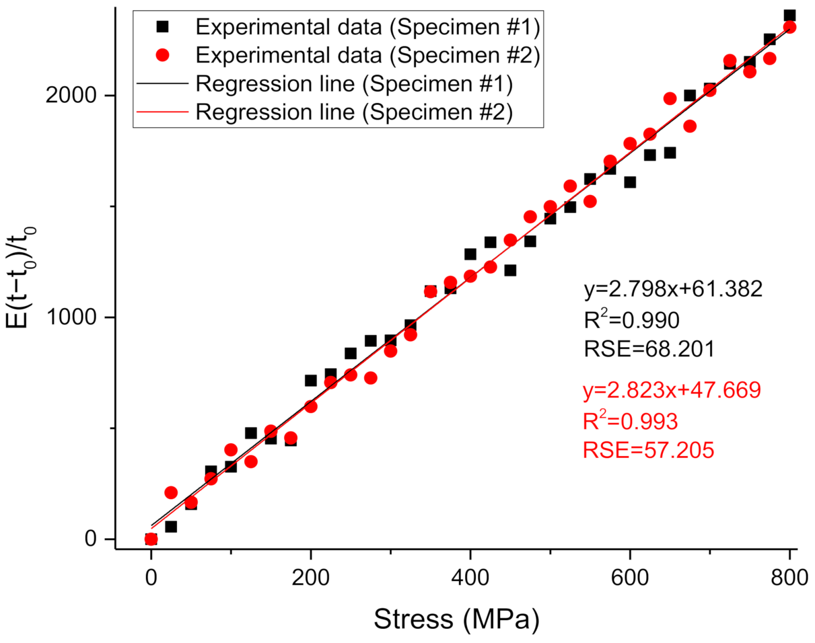
The LCR wave signals received from each receiver were acquired while the load applied to the test piece was changing. This was done to confirm that a difference in travel time of the ultrasonic waves appeared according to the stresses. Moreover, according to Equation (4), the acoustoelastic coefficient could be measured using the slope of the stress vs. graph for the tensile test results. Figure 9 shows the respective results obtained in tensile tests on two specimens.
To perform an uncertainty analysis of the results of the tensile test, corrections through linear regression were performed using a least-squares method. The regression lines obtained through the experimental results were and , respectively. In other words, the slopes of these lines, 2.798 and 2.823, are the acoustoelastic coefficients of each rail specimen used in the experiments. The coefficients of determination (R2) for these regression lines were 0.990 and 0.993; that is, the correlation coefficients (R) were 0.995 and 0.997. Each residual standard error was 68.201 and 57.205. That is, each result was proven to be very reliable because they almost converged to the value of 1. In addition, the values of the acoustoelastic coefficients obtained in two results did not differ significantly. Therefore, it was demonstrated that the acoustoelastic coefficients obtained through constant tensile load values can be used to measure the residual stress of rails while they are in use in the field.
Through this test method, in order to verify that the time differences are clearly indicated according to the stress differences, the vs. stress graph for the tensile load is shown in Figure 10.
The regression lines of these graphs were and . The coefficients of determination for these regression lines were 0.990 and 0.993, that is, the correlation coefficients were 0.995 and 0.997, respectively. The residual standard errors were 24.412 and 20.308. The evidence of this approach is that the results calculated through this experiment have proven to be very reliable. Therefore, it was also confirmed that the ultrasonic technique using LCR waves can be used to measure sensitively the tensile stress.
Figure 11 shows the results of the experiment to measure the residual stresses of the head part on the rail samples using the average value of the obtained acoustoelastic coefficients.
Compressive stress is displayed as a negative number on this graph, just as negative values are usually used to indicate compaction. In region A (range −20 to −5 mm), only sample 3 showed relatively high absolute values of residual stress. This was expected because trains with wheels directly contacting region A of the rail from which sample 3 was extracted passed relatively more than the other two rails. On the other hand, for all three samples, lower residual stress values were calculated in region B (range −5 to 10 mm) than in other regions. In region C (range 10 to 25 mm), high compressive residual stress values were calculated from sample 1 and sample 3. Relatively, the compressive residual stresses in sample 2 were evenly distributed without significant difference in all regions. This is the basis that the rail from which sample 2 was extracted was used with more uniform contact with the surface of the wheels than the other rails. Therefore, it can be inferred that sample 2 was extracted from relatively straight rail tracks, and sample 1 and sample 3 were extracted from outer tracks of bends. In this way, the residual stress values of the rail can be calculated from the ultrasonic signals obtained by scanning the rail using the developed LCR wave probe. Using the calculated residual stress values, it is possible to analyze the stress distribution within the rail and to determine how much the rail has been used and whether it is currently safe to use.
5. Conclusions
The main objective of this study was to confirm the potential for application of a new ultrasonic method for the non-destructive measurement of residual stress in rails. For this purpose, the measurement of residual stress of rails was carried out using LCR waves. According to the results of the studies conducted, the following conclusions can be drawn:
- (1)
- A probe consisting of one transmitter and two receivers was fabricated using PZT piezoelectric elements with a center frequency of 2.25 MHz and a wedge made of PMMA material.
- (2)
- The acoustoelastic coefficient was calculated through a plurality of tensile tests. By analyzing the correlation between stress and travel time, it was found that the regression lines whose slope values are the acoustoelastic coefficient are very close to straight lines. This indicates that the calculated acoustoelastic coefficient values have high reliability, and stress can be measured using these values.
- (3)
- Residual stresses on used rails were measured using the calculated acoustoelastic coefficients, and their distributions were analyzed. Using rail specimens under different conditions, it was verified whether the characteristics of the residual stress inherent in the rails could be grasped through the measured values. Through this process, it has been proven that ultrasonic testing using LCR waves is a non-destructive measurement technique that can be applied for accurate residual stress measurement of used rails.
Because LCR waves travel to different penetration depths depending on the frequency, if LCR wave probes with different frequencies are manufactured and residual stress values are measured for the same location of the subject made of a material for which the acoustoelastic coefficient has already been calculated through a tensile testing, even the stress gradient of the subject can be obtained. In addition, because this approach uses equipment that is not large (or which could be miniaturized), it has also been confirmed that it could be applied to measure stress in real time under actual field conditions by constructing a portable system. Therefore, it is possible to overcome the limitations of the existing X-ray diffraction method or Barkhausen noise method used to measure the residual stress of rails. It can also be seen that more specific information can be obtained more simply and quickly from the field directly, which has the additional potential to be a suitable technique.
Author Contributions
Conceptualization, K.-B.K.; Data curation, G.K.; Formal analysis, G.K.; Funding acquisition, J.-H.P. and M.Y.C.; Investigation, Y.-I.H.; Methodology, Y.-I.K. and K.-B.K.; Project administration, M.Y.C. and K.-B.K.; Resources, J.-H.P.; Software, Y.-I.H. and G.K.; Supervision, K.-B.K.; Validation, Y.-I.K.; Visualization, Y.-I.H.; Writing—original draft, Y.-I.H.; Writing—review & editing, K.-B.K. All authors have read and agreed to the published version of the manuscript.
Funding
This research was partially supported by a “development of safety measurement technology for infrastructure industry” grant funded by the Korea Research Institute of Standards and Science (KRISS-2021-GP2021-0008) and “development of IoT-based rail break and buckling detection system for climate change” grant (21CTAP-C152115-03) among the railroad technology research projects supported by the Korea Agency for Infrastructure Technology Advancement (KAIA).
Institutional Review Board Statement
Not applicable.
Informed Consent Statement
Not applicable.
Data Availability Statement
Not applicable.
Conflicts of Interest
The authors declare no conflict of interest.
References
- Kudryavtsev, Y.; Kleiman, J. Fatigue of welded elements: Residual stresses and improvement treatments. Weld. World Lond. 2007, 51, 255. [Google Scholar]
- Rossini, N.; Dassisti, M.; Benyounis, K.; Olabi, A.G. Methods of measuring residual stresses in components. Mater. Des. 2012, 35, 572–588. [Google Scholar] [CrossRef] [Green Version]
- Kelleher, J.; Prime, M.; Buttle, D.; Mummery, P.; Webster, P.; Shackleton, J.; Withers, P. The Measurement of Residual Stress in Railway Rails by Diffraction and other Methods. J. Neutron Res. 2003, 11, 187–193. [Google Scholar] [CrossRef]
- Mirković, N.; Brajović, L.; Malović, M. Methods for determination of residual stress in rail. In Proceedings of the XVIII Scientific-Expert Conference on Railways-RAILCON 18, Niš, Serbia, 11–12 October 2018; pp. 113–116. [Google Scholar]
- Li, Z.; He, J.; Teng, J.; Wang, Y. Internal Stress Monitoring of In-Service Structural Steel Members with Ultrasonic Method. Materials 2016, 9, 223. [Google Scholar] [CrossRef] [Green Version]
- Palkowski, H.; Brück, S.; Pirling, T.; Carradò, A. Investigation on the Residual Stress State of Drawn Tubes by Numerical Simulation and Neutron Diffraction Analysis. Materials 2013, 6, 5118–5130. [Google Scholar] [CrossRef] [PubMed] [Green Version]
- Fitzpatrick, M.E.; Fry, A.T.; Holdway, P.; Kandil, F.A.; Shackleton, J.; Suominen, L. Determination of Residual Stresses by X-ray Diffraction; National Physical Laboratory: Teddington, UK, 2005. [Google Scholar]
- Buttle, D.J.; Moorthy, V.; Shaw, B.; Lord, J.D. Determination of Residual Stresses by Magnetic Methods; National Physical Laboratory: Teddington, UK, 2006. [Google Scholar]
- Mierczak, L.; Jiles, D.C.; Fantoni, G. A New Method for Evaluation of Mechanical Stress Using the Reciprocal Amplitude of Magnetic Barkhausen Noise. IEEE Trans. Magn. 2011, 47, 459–465. [Google Scholar] [CrossRef]
- Hwang, Y.I.; Kim, Y.I.; Seo, D.C.; Seo, M.K.; Lee, W.S.; Kwon, S.; Kim, K.B. Experimental Consideration of Conditions for Measuring Residual Stresses of Rails Using Magnetic Barkhausen Noise Method. Materials 2021, 14, 5374. [Google Scholar] [CrossRef] [PubMed]
- Zou, D.; Liu, T.; Liang, C.; Huang, Y.; Zhang, F.; Du, C. An experimental investigation on the health monitoring of concrete structures using piezoelectric transducers at various environmental temperatures. J. Intell. Mater. Syst. Struct. 2015, 26, 1028–1034. [Google Scholar] [CrossRef]
- Zou, D.; Liu, T.; Huang, Y.; Zhang, F.; Du, C.; Li, B. Feasibility of water seepage monitoring in concrete with embedded smart aggregates by P-wave travel time measurement. Smart Mater. Struct. 2014, 23, 067003. [Google Scholar] [CrossRef]
- Zou, D.; Liu, T.; Qiao, G.; Huang, Y.; Li, B. An experimental study on the performance of piezoceramic-based smart aggregate in water environment. IEEE Sens. J. 2014, 14, 943–944. [Google Scholar] [CrossRef]
- Ploix, M.A.; El Guerjouma, R.; Moysan, J.; Corneloup, G.; Chassignole, B. A steel welds for experimental and modeling NDT. J. Adv. Sci. 2005, 17, 76–81. [Google Scholar] [CrossRef] [Green Version]
- Spies, M.; Schneider, E. Nondestructive analysis of textures in rolled sheets by ultrasonic techniques. Texture Stress Microstruct. 1990, 12, 219–231. [Google Scholar] [CrossRef] [Green Version]
- Palanichamy, P.; Joseph, A.; Jayakumar, T.; Raj, B. Ultrasonic velocity measurements for estimation of grain size in austenitic stainless steel. NDT E Int. 1995, 28, 179–185. [Google Scholar] [CrossRef]
- Hwang, Y.I.; Sung, D.; Kim, H.J.; Song, S.J.; Kim, K.B.; Kang, S.S. Propagation and Attenuation Characteristics of an Ultrasonic Beam in Dissimilar-Metal Welds. Sensors 2020, 20, 6259. [Google Scholar] [CrossRef]
- Gür, C.H.; Cam, I. Comparison of magnetic Barkhausen noise and ultrasonic velocity measurements for microstructure evaluation of SAE 1040 and SAE 4140 steels. Mater. Charact. 2007, 58, 447–454. [Google Scholar] [CrossRef]
- Nam, Y.H.; Kim, Y.I.; Nahm, S.H. Evaluation of fracture appearance transition temperature to forged 3Cr–1Mo–0.25V steel using ultrasonic characteristics. Mater. Lett. 2006, 60, 3577–3581. [Google Scholar] [CrossRef]
- Crecraft, D. The measurement of applied and residual stresses in metals using ultrasonic waves. J. Sound Vib. 1967, 5, 173–192. [Google Scholar] [CrossRef]
- Lh’emery, A.; Calmon, P.; Chatillon, S.; Gengembre, N. Modeling of ultrasonic fields radiated by contact transducer in a component of irregular surface. Ultrasonics 2002, 40, 231–236. [Google Scholar] [CrossRef]
- Egle, D.M.; Bray, D.E. Measurement of acoustoelastic and third-order elastic constants for rail steel. J. Acoust. Soc. Am. 1976, 60, 741–744. [Google Scholar] [CrossRef]
- Li, Z.; He, J.; Teng, J.; Huang, Q.; Wang, Y. Absolute stress measurement of structural steel members with ultrasonic shear-wave spectral analysis method. Struct. Heal. Monit. 2019, 18, 216–231. [Google Scholar] [CrossRef]
- Bray, D.E.; Tang, W. Subsurface stress evaluation in steel plates and bars using the LCR ultrasonic wave. Nucl. Eng. Des. 2001, 207, 231–240. [Google Scholar] [CrossRef]
- Dos Santos, A.A., Jr.; Bray, D.E. Comparison of acoustoelastic methods to evaluate stresses in steel plates and bars. J. Press. Vessel Technol. 2002, 124, 354–358. [Google Scholar] [CrossRef]
- Andrino, M.H.; dos Santos, A.A., Jr.; Bray, D.E.; Trevisan, R.E. Stress relaxation in aluminum welding using ultrasonic method. In Proceedings of the ASME Pressure Vessels and Piping Conference, San Antonio, TX, USA, 22–26 July 2007; Volume 42835, pp. 157–165. [Google Scholar]
- Javadi, Y.; Hloch, S. Employing the LCR waves to measure longitudinal residual stresses in different depths of a stainless steel welded plate. Adv. Mater. Sci. Eng. 2013. [Google Scholar] [CrossRef] [Green Version]
- Javadi, Y.; Pirzaman, H.S.; Raeisi, M.H.; Najafabadi, M.A. Ultrasonic inspection of a welded stainless steel pipe to evaluate residual stresses through thickness. Mater. Des. 2013, 49, 591–601. [Google Scholar] [CrossRef]
- Javadi, Y.; Plevris, V.; Najafabadi, M.A. Using LCR ultrasonic method to evaluate residual stress in dissimilar welded pipes. Int. J. Innov. Manag. Technol. 2013, 4, 170–174. [Google Scholar]
- Javadi, Y.; Najafabadi, M.A. Comparison between contact and immersion ultrasonic method to evaluate welding residual stresses of dissimilar joints. Mater. Des. 2013, 47, 473–482. [Google Scholar] [CrossRef]
- Javadi, Y.; Akhlaghi, M.; Najafabadi, M.A. Nondestructive Evaluation of Welding Residual Stresses in Austenitic Stainless Steel Plates. Res. Nondestruct. Evaluation 2014, 25, 30–43. [Google Scholar] [CrossRef]
- Javadi, Y.; Sadeghi, S.; Najafabadi, M.A. Taguchi optimization and ultrasonic measurement of residual stresses in the friction stir welding. Mater. Des. 2014, 55, 27–34. [Google Scholar] [CrossRef]
- Sadeghi, S.; Najafabadi, M.A.; Javadi, Y.; Mohammadisefat, M. Using ultrasonic waves and finite element method to evaluate through-thickness residual stresses distribution in the friction stir welding of aluminum plates. Mater. Des. 2013, 52, 870–880. [Google Scholar] [CrossRef]
- Javadi, Y.; Akhlaghi, M.; Najafabadi, M.A. Using finite element and ultrasonic method to evaluate welding longitudinal residual stress through the thickness in austenitic stainless steel plates. Mater. Des. 2013, 45, 628–642. [Google Scholar] [CrossRef]
- Liu, H.; Li, Y.; Li, T.; Zhang, X.; Liu, Y.; Liu, K.; Wang, Y. Influence factors analysis and accuracy improvement for stress measurement using ultrasonic longitudinal critically refracted (LCR) wave. Appl. Acoust. 2018, 141, 178–187. [Google Scholar] [CrossRef]
- Santos, A.A.; Bray, D.E. Ultrasonic stress measurement using PC based and commercial flaw detectors. Rev. Sci. Instrum. 2000, 71, 3464–3469. [Google Scholar] [CrossRef] [Green Version]
- Martin, L.P.; Dadon, D.; Rosen, M. Evaluation of Ultrasonically Determined Elasticity-Porosity Relations in Zinc Oxide. J. Am. Ceram. Soc. 1996, 79, 1281–1289. [Google Scholar] [CrossRef]
- Jun, T.S.; Hofmann, F.; Belnoue, J.; Song, X.; Hofmann, M.; Korsunsky, A.M. Triaxial residual strains in a railway rail measured by neutron diffraction. J. Strain Anal. Eng. Des. 2009, 44, 563–568. [Google Scholar] [CrossRef]
- Webster, P.J.; Hughes, D.J.; Mills, G.; Vaughan, G.B.M. Residual Stresses in Railway Rails—The FaME38. Mater. Sci. Forum 2002, 404–407, 767–772. [Google Scholar] [CrossRef]
- Soleimani, H.; Moavenian, M. Tribological Aspects of Wheel–Rail Contact: A Review of Wear Mechanisms and Effective Factors on Rolling Contact Fatigue. Urban. Rail Transit. 2017, 3, 227–237. [Google Scholar] [CrossRef] [Green Version]
- Lo, K.H.; Mummery, P.; Buttle, D. Characterisation of residual principal stresses and their implications on failure of railway rails. Eng. Fail. Anal. 2010, 17, 1273–1284. [Google Scholar] [CrossRef]
- Railway Technology Review Committee. KRS TR 0001-15(R), Rail; Korean Railway Standards: Sejong, Korea, 2006. [Google Scholar]
- Song, W.; Xu, C.; Pan, Q.; Song, J. Nondestructive testing and characterization of residual stress field using an ultrasonic method. Chin. J. Mech. Eng. 2015, 29, 365–371. [Google Scholar] [CrossRef]
Figure 1.
Excitation of the LCR wave through transmitter and wedge [35].
Figure 1.
Excitation of the LCR wave through transmitter and wedge [35].

Figure 2.
Wheel-rail contact geometry [40].
Figure 2.
Wheel-rail contact geometry [40].
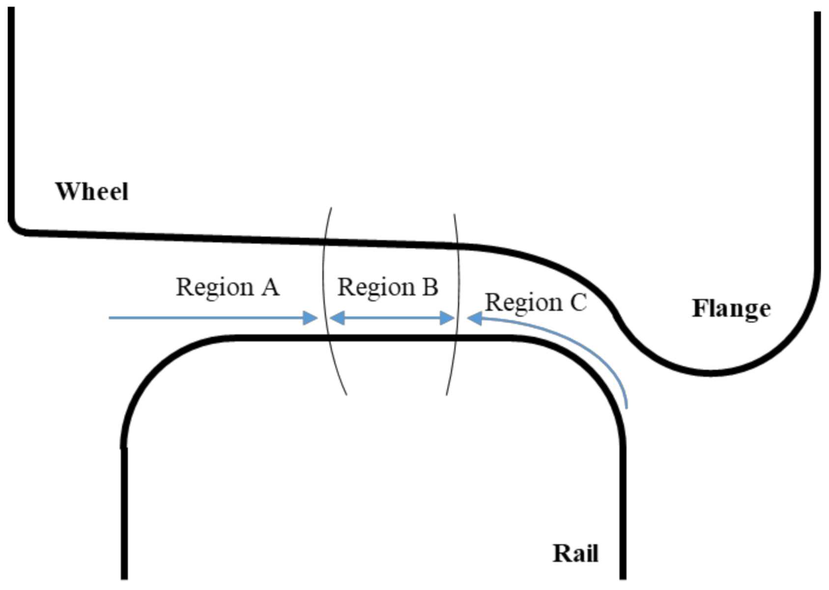
Figure 3.
Cross-section of a KR60 rail [42].
Figure 3.
Cross-section of a KR60 rail [42].

Figure 4.
Photograph of specimens manufactured for the tensile tests.

Figure 5.
Photograph of a manufactured LCR wave probe.

Figure 6.
Photograph of the experimental setup for measuring tensile stress using LCR waves.

Figure 7.
Photograph of the experimental setup for measuring residual stress using LCR waves.
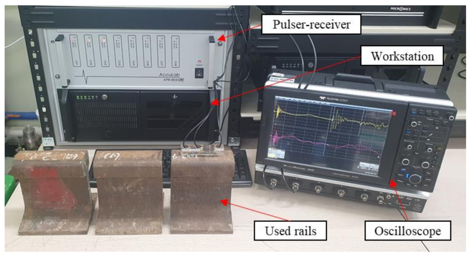
Figure 8.
Received signals used for calculating travel times.

Figure 9.
Stress vs. graphs obtained from the tensile tests for two rail specimens.

Figure 10.
The vs. stress graphs obtained from the tensile tests for two rail specimens.

Figure 11.
Results of measuring residual stresses from the head part of the rail samples.


Table 1.
Mechanical properties of KR60 rail [42].
Table 1.
Mechanical properties of KR60 rail [42].
| Yield Strength [MPa] | Elongation Percentage [%] | Hardness [HBW] | Modulus of Elasticity [MPa] | Linear Expansion Coefficient [mm/°C] |
|---|---|---|---|---|
| >800 | >10 | >235 | 210,000 | 1.14 × 10⁻⁵ |
Publisher’s Note: MDPI stays neutral with regard to jurisdictional claims in published maps and institutional affiliations. |
© 2021 by the authors. Licensee MDPI, Basel, Switzerland. This article is an open access article distributed under the terms and conditions of the Creative Commons Attribution (CC BY) license (https://creativecommons.org/licenses/by/4.0/).
Share and Cite
MDPI and ACS Style
Hwang, Y.-I.; Kim, G.; Kim, Y.-I.; Park, J.-H.; Choi, M.Y.; Kim, K.-B. Experimental Measurement of Residual Stress Distribution in Rail Specimens Using Ultrasonic LCR Waves. Appl. Sci. 2021, 11, 9306. https://doi.org/10.3390/app11199306
AMA Style
Hwang Y-I, Kim G, Kim Y-I, Park J-H, Choi MY, Kim K-B. Experimental Measurement of Residual Stress Distribution in Rail Specimens Using Ultrasonic LCR Waves. Applied Sciences. 2021; 11(19):9306. https://doi.org/10.3390/app11199306
Chicago/Turabian StyleHwang, Young-In, Geonwoo Kim, Yong-Il Kim, Jeong-Hak Park, Man Yong Choi, and Ki-Bok Kim. 2021. "Experimental Measurement of Residual Stress Distribution in Rail Specimens Using Ultrasonic LCR Waves" Applied Sciences 11, no. 19: 9306. https://doi.org/10.3390/app11199306
Note that from the first issue of 2016, this journal uses article numbers instead of page numbers. See further details here.