Implementation of a Novel Inertial Mass System and Comparison to Existing Mass-Rig Systems for Shake Table Experiments


1
Escuela de Ingeniería Civil, Pontificia Universidad Católica de Valparaíso, Valparaíso 2362804, Chile
2
Department of Civil & Environmental Engineering, Portland State University, Portland, OR 97201, USA
*
Author to whom correspondence should be addressed.
Appl. Sci. 2021, 11(2), 692; https://doi.org/10.3390/app11020692
Submission received: 11 December 2020
/
Revised: 9 January 2021
/
Accepted: 10 January 2021
/
Published: 12 January 2021
(This article belongs to the Section Civil Engineering)
Abstract
:Shake table testing is one of the more effective experimental approaches used to study and evaluate seismic performance of structures. Reduced-scale models can still result in large-scale specimens where incorporating the required inertial mass effectively and safely can be challenging. This study proposes a new system of arranging the mass in the experiments that combines the realism of mass participation during earthquake excitation when supported by the shake table with laboratory practicality considerations of the mass positioned off the specimen. The characteristics and dynamic motion equations for the proposed system are described and applied to shake table experiments involving large-scale cantilevered columns. Using data from large-scale experiments to validate a numerical model, the proposed approach was numerically compared to two other testing approaches. Based on the measured performance and the validated numerical simulations, it can be concluded that the proposed inertial mass system can result in seismic performance as if the mass was placed directly on top of the specimen. Combined with the advantages of reduced setup time, incorporating safety restraints and direct measurement of inertial loads, the proposed system can be suitably used for effective shake table testing of large-scale specimens taken to non-linear near-collapse performance levels.
1. Introduction
To diminish the existing vulnerabilities of infrastructure to seismic hazards and fulfill the ever-increasing structural demands of modern codes, the earthquake engineering community has steadily worked over the years to enhance knowledge on the behavior of structures under severe earthquakes. Experimental evaluation of existing and new seismic design methodologies can be one of the most effective ways to help engineering practice understand, accept, and utilize new information in their designs. Several experimental procedures can be used to simulate and measure the behavior of structural systems and components under simulated earthquake loads, including quasi-static testing, hybrid simulation and shake table testing. Quasi-static tests do not simulate ground motion and cannot reproduce rate-dependent effects and hybrid simulation relies on computer models for inertia effects, leaving shake table testing as one of the most direct and effective structural testing methods [1]. Structural response generated during shake table tests are the most consistent with the actual structural responses that occur during earthquakes. In fact, these types of experiment have the advantage of reproducing recorded accelerations of real earthquakes with high reliability while also maintaining the real dynamic rate characteristics, which include all inertial effects of the test specimen. These realistic conditions are highly useful in validating and calibrating models for seismic design, in performing evaluation of structures and in conducting seismic risk assessment [2,3].
Despite the aforementioned advantages of shake table testing, some distinctive challenges must be taken into consideration and overcome to successfully carry out such testing. Many of the difficulties are linked to practical implementations and economic constraints. Avoiding scaling effects by testing entire systems at full-scale [4,5,6] is desired, but such endeavors require large facilities and expensive specimens. Space limitations in experimental facilities, equipment capacity and limited funding generally impose limits on the scope of the experiments. As a result, shake tables of reduced size and limited payload capacity are typically utilized, which in turn results in testing on reduced-scale specimens and on structural subassemblies instead of entire systems. To be as realistic as possible, even at reduced scale the specimens are often large-scale.
Whenever the shake table experiments include large-scale specimens, a substantial amount of mass needs to be provided in order to achieve sufficient inertia to obtain the desired dynamic characteristic as well as to be able to generate sufficient forces to reach strength capacity of the specimen. This is especially important for the realistic cases intended to evaluate seismic performance levels approaching or exceeding collapse [7]. However, the downside of providing the needed mass can introduce safety issues caused by instability of the test model or by collapse under the simulated seismic excitations [1]. Accordingly, alternative methods and devices have been developed for externally supporting and securing the additional mass to the specimen and transmitting the inertial forces to the test model [8]. The various options come with benefits and drawbacks, whereby the implementation of a particular system will depend on the test objectives and the available resources [1]. Despite the wide variety of solutions, the inertial loading systems have not necessarily satisfactorily addressed all the concerns associated with safety, setup time, and cost.
This article aims to propose and validate a new configuration of the inertial mass system to mitigate some of the shortcomings of past shake table testing configurations. The relevant system characteristics and the dynamic equations of motion are presented and discussed in detail. The new system has been used with success in dynamic experiments of cantilever-type reinforced concrete (RC) bridge columns pushed to near-collapse performance levels. Details of the experimental verification of the proposed system are not presented in this work, but can be found in the literature [9]. As this work is focused on dynamic testing methods for bridge columns, a review and discussion of two different and prominent mass-carrying approaches used for shake table tests of cantilever RC columns are included herein. Later, these existing as well as the proposed approaches are numerically compared with 2D non-linear finite element models in OpenSees [10].
2. Research Approach
The approach followed in this research included four main parts, as outlined in Figure 1. First, a literature review was undertaken to examine and identify the advantages and shortcomings of existing inertial loading systems used in shake table experiments on large-scale structural specimens. Second, a new inertial system was conceived and analytically assessed by determining the associated dynamic equation of motions of the system. Third, the proposed system was experimentally and numerically evaluated to study the seismic performance when incorporating large-scale bridge column specimens. Finally, non-linear modeling of the proposed system was used to compare performance to the other prominent inertial loading setups.
3. Inertial Systems for Shake Table Tests
Some challenges need to be resolved to successfully use shake table testing to evaluate the seismic performance of structural elements, substructures, or entire structural systems. One of these challenges is related to providing the necessary representative forces during the real-time dynamic tests, especially when the actual mass of the test specimen is not sufficiently high. To accomplish this, additional inertial mass must be considered as a part of the experimental setup. The amount of extra inertial mass will depend on the size of the test model (compared to the prototype structure) and the experimental program (e.g., when simulating structural damage at different performance levels). Above all, the total mass is dictated by the size and capability of the shake table, which is critical for small shake tables where the total payload capacity must be used [11]. Under this scenario, different configurations of inertial loading system for supporting and securing the extra mass and providing the representative inertial forces have been utilized in different shake table experiments reported in the literature [8]. Among these, placement of the load-generating mass directly on the top of specimens and the use of external mass-carrying devices based on linear sliding, rotational, and pendulum mechanisms are commonly used. Although more sophisticated testing configurations may be developed, these configurations provide a range of options for diverse kinds of research program. In particular, this work is focused on two prominent inertial mass configurations: a load-generating mass device attached directly on the model’s top and a system with the mass mounted on a pinned supporting frame that is external to the simulator. Their advantages and drawbacks are discussed below.
3.1. Inertial Mass Supported by the Specimen
Several shake table experiments on cantilever RC columns have been performed by positioning the inertial mass directly on top of the specimen’s head and subjecting it to the earthquake ground motion record. Examples of such studies can be found in the works by Mosalam et al. [12], Sakai et al. [13], Schoettler et al. [6], and Ge et al. [14]. In this configuration, the axial force on the column model generated by the superstructure weight and the P-Δ effect can be replicated. While this procedure has been widely used, there are major deficiencies associated with it. One of the key disadvantages of this setup is that its arrangement leads to delays and higher costs due to mass removal and reinstallation when the experimental program consists of several specimens. Furthermore, an auxiliary-supporting system must be considered for protection during and after testing in the case of large displacements or a possible collapse of the specimen. Figure 2 and Figure 3 show two setups where the inertial mass is directly on top of the test specimen.
Another disadvantage of this configuration is the size of the inertial mass system, which can be rather large compared to the specimen, as shown in the figures. The large size of the blocks could result in additional higher mode effects associated with rotational deformation demands at the top of the specimen’s head. It is worth noting that these demands are not encountered in field conditions since the inertial mass for a given column is constrained in the rotational degree of freedom.
3.2. Inertial Mass Supported by an External System
Another configuration for including the additional mass in shake table testing is to locate it outside the table. In this configuration, the additional mass is positioned on an articulated supporting frame adjacent to the shaking platform, and it is attached to the test specimen through a pinned-end connection that allows free rotation and, therefore, transmits axial force only. Relevant advantages are associated with this configuration [8]. Taking the additional mass off from the platform reduces the risk of damaging the test equipment and laboratory personnel if lateral instability of the specimen occurs during testing. Another benefit of this approach is the decrease in the time taken to assemble and disassemble a test setup. This is because the simple connection between the mass-rig and the specimen needs to be disconnected from the model only. Therefore, if the experimental program includes many tests, the research time decreases considerably. Additionally, another benefit of this configuration is that it allows the use of the full capabilities of the shake table since the performance of the shaking platform depends on the weight acting on the simulator.
In the literature, three types of mass-rig system placed outside the shake table can be distinguished: a linear sliding, a rotational, and a pendulum system. Among these systems, the rotational mass-rig has been used in experiments involving RC columns as the specimen, as proposed by Laplace et al. [15]. This mass-rig system is presented in Figure 4 and consists of an articulated frame to provide the inertial loading during the testing program. The axial force applied to the column is accomplished by means of a steel spreader beam connected to the top of the specimen’s head and two center-hole jacks. To restrict the translation of the inertial mass, constraint cables must be included. In the case of column failure, the mass-rig translates until reaching the maximum displacement preset by the restraining cables. Thus, safety concerns are eliminated if the specimen fails. Furthermore, the mass-rig restrains the out-of-plane movement of the specimen and, therefore, additional elements for this purpose are not necessary. Another benefit of this mass-rig configuration, as indicated above, is that it also enables quick installation and removal of specimens.
Although this system eliminates various problems related to the testing of cantilever columns using shake tables, it still has some concerns associated with the proper representation of P-Δ effects. From their experimental findings, Laplace et al. [15] concluded that the experimental shear forces were lower than those estimated from the numerical analysis including P-Δ effects.
Conclusions from these two types of test indicate that (1) placing a large mass on top of a column leads to higher mode effects that are not typically observed in an actual bridge configuration and that (2) placing the additional mass on an external mass-rig system does not properly represent the P-Δ effects that cantilever columns undergo during earthquake ground motions. In an effort to overcome these two issues, a new inertial mass system (IMS) is introduced. In this configuration, the extra inertial mass is supported by the shake table by employing a stiff-pinned column attached to the platform. The features of this system are described in detail, and the equations of motion of the internal system and the shake table are developed. It is worth mentioning that the proposed system was successfully used in the dynamic testing of six RC bridge column specimens, whose results and discussion can be found in the literature [9].
4. Proposed System
4.1. System Description
Based on the existing inertial configurations for shake table tests, the authors conceived and developed a new inertial mass testing system. The IMS, which is located on the shake table platform, was explicitly developed to enable the shake table experiment of single cantilever-type RC columns subjected to unidirectional earthquake excitations [9], although minor modifications to the inertial system or the test sample dimensions could allow other specimens to be tested. A schematic of the proposed system is depicted in Figure 5. The IMS comprises a steel column that is pin-connected to a supporting W-beam, which is connected to the shaking platform via four high-strength posttensioning rods. The required inertial mass is incorporated into the system by using a predefined number of concrete blocks, which are connected to the steel column via high-strength posttensioning rods at a height dictated by the height of the test specimen. However, auxiliary components of the system (e.g., steel column and swiveled link) also provide a minor amount of the inertial mass. The IMS is connected to the head of the specimen through a pinned-end rigid link. The link was designed to transmit the inertial forces created on the IMS to the specimen, allowing only in-plane rotation. To monitor the lateral force transferred to the specimen, a load cell was mounted in the link close to the test specimen. Additionally, to guarantee that the concrete blocks remain connected and that the inertial forces are transferred via the rigid link while shaking, a W-beam was placed at the back of the concrete masses using various posttension rods. It is worth mentioning that one end of the stiff link was posttensioned to the W-beam attached to the IMS.
A safety system external to the shake table system was designed to catch the IMS in the occurrence of significant displacements or specimen failure. The steel-braced safety frame consisted of wide-flange sections for both the columns and beams and was fixed to the laboratory strong floor using high-strength rods. The two closer bays of the safety frame were braced together using a series of angle braces in a cross shape in the north-south direction (Figure 5a), whereas chevron bracing was used in the east–west direction (Figure 5b). It is important to mention that the motion on the platform is stopped when the concrete masses impact the longitudinal beams of the safety frame. A maximum drift of 63.5 cm (25 in) is allowed by the safety system in the direction of motion. In order to avoid out-of-plane motion of the IMS, a caster was connected to the web of each longitudinal beam, as shown in Figure 5b.
Since the IMS was composed of only a steel column and concrete masses, the setting process of an RC specimen can be completed in a short time. As illustrated in Figure 6, the sequence of assembling the IMS includes the following steps: (a) attaching the supporting W-beam to the shaking platform with the clevis (Figure 6a), (b) raising the steel column and connecting it to the clevis (Figure 6b), (c) attaching the concrete blocks to the steel column and placing the steel back beam at the required height (Figure 6c), (d) setting the RC specimen by securing its footing to the shake table via high-strength posttensioning rods, (e) connecting the stiff link between the steel column and the head of the RC specimen, and (f) attaching the axial load system on the top of the RC column.
4.2. Advantages and Disadvantages
There are major benefits of the proposed inertial system, as discussed hereafter. (1) Safety: during column failure or if the collapse performance level must be reached, large displacements may occur. In this case, the safety mechanism limits the displacement of the mass (Figure 7). Then, the safety of laboratory personnel, equipment, and specimen instrumentation is also improved. On the other hand, if the inertial masses are attached directly on top of the specimen’s head, when the column fails or the concrete blocks fall, the instrumentation and shake table components could sustain permanent damage. (2) Preparation time: since the connection between the masses and specimen is simple, the time to assemble and disassemble the test setup decreases. Prior to testing, the IMS rests on the safety catch using hydraulic jacks as supports. Once the specimen is mounted on the shake table, the masses are lifted by applying pressure to the jacks and then connecting the rigid link to the specimen’s head. Therefore, when a test matrix considers several tests, the research time reduces substantially. (3) Small out-of-plane displacement: The use of the pinned-end stiff link with only free in-plane rotation allowed (transverse rotation restrained) diminishing or nearly removing the out-of-plane displacements. However, to ensure pure in-plane behavior, one caster was attached to each longitudinal beam of the safety catch frame to restrain the out-of-plane displacement of the IMS. The steel column is provided with two steel plates (one on each side) where the casters slide if out-of-plane displacements occur. It is worth noting that the gap between the plates and the caster was only 4.8 mm (3/16 inches) on each side.
The key downside of the IMS is that the full capabilities of the shake table may not be used if the extra mass is relatively large compared to the one used in the IMS. This condition arises because the efficiency of the shake table is correlated to the weight acting on the simulator [11]. Additionally, by putting the inertial mass on the simulator, substantial overturning moments are incorporated into the system and may thus pose a significant challenge for proper control in the closed-loop system. Another downside of the IMS is that axial forces required to simulate the weight of the superstructure in the case of bridge columns are not added. Therefore, another system is required to resolve this problem. For the proposed IMS, two hydraulic jacks apply the axial loads on the specimen through high-strength rods.
4.3. Equation of Motion
As discussed in the previous section, the IMS greatly simplifies the test setup and specimen preparation. Nevertheless, the specimen’s loading and stiffness are impacted through the P-Δ effect at large displacements. The significance and extent of this effect can be examined by the dynamic equation of motion for the entire device depicted in Figure 8. For a non-linear single-degree-of-freedom (SDOF) system with constant viscous damping [16] subjected to horizontal earthquake motion, the dynamic equation of motion can be written as:
where m is the oscillator’s mass; c is the damping coefficient; k(t) is the stiffness; x, , and are the oscillator’s displacement, velocity and relative acceleration, respectively; and is the ground motion acceleration.
For the system shown in Figure 8, Equation (1) can be rewritten as:
For Equation (2), m is the lateral effective mass of the complete system and is equal to:
where m1 is the IMS mass, m2 is the mass of the rigid link system, m3 is the axial load system’s mass on the column, m4 is the specimen mass, H is the specimen height, and W″ is the IMS effective weight, which, in turn, is calculated as:
where g is the gravity acceleration (9.81 m/s2). The total displacement of the whole system, xabs, is defined as:
where x(t) is the relative column displacement and xg(t) is the shake table displacement. The values of the above variables are listed in Table 1.
4.4. Calculation of the Lateral Force
The specimen’s lateral shear force (Fcol) is the sum of the spring and damping forces:
The force acting on the test specimen (Fcol) may be obtained by employing any of three procedures, namely, through the use of a load cell, the equation of motion, or an accelerometer.
4.4.1. Using a Load Cell
The pinned-end rigid link (Figure 5) was instrumented with a 250 kN load cell that was placed just before the swivel attached to the head of the column and connected to the data acquisition system. The load cell measures the lateral force acting on the specimen due to the inertial force from the IMS and the P-∆ force created from the overturning moment of the IMS. However, it does not include the inertial mass of the pinned-end rigid link between the load cell and specimen, the axial load system, or the contribution of the specimen to the inertial force. Therefore, the lateral force acting on the column is defined as:
where Fcol is the force measured by the load cell, is the absolute acceleration measured for the specimen and ψ1 is the percentage of mass of the link system between the load cell and specimen. Fcol and are positive in the direction towards the specimen.
4.4.2. Using the Equation of Motion
The second procedure for obtaining Fcol is from the equation of motion. Substituting Equation (6) into Equation (2) and rearranging terms:
According to Equation (5), Equation (8) can be rewritten as:
It is worth noting that the lateral force Fcol calculated using Equation (7) or Equation (9) must be adjusted to account for the effects of the horizontal portion of the applied axial force at large displacements, as described in the next section.
4.5. Calculation of P-∆ Force
The P-∆ effect was defined as the corresponding lateral force due to the overturning moment, which results from the multiplication of the vertical force and the lateral displacement. Two components are contributing to P-∆ in this study. First, the P-∆ generated from the overturning moment of the IMS. To calculate the equivalent lateral load due to the IMS, the effect was defined as:
Since Equation (10) is included in the force measured by the load cell, the column shear force remains the same as that in Equation (7). The second P-∆ effect was due to the axial load system. This effect depends on the axial load line-of-force, which pivots near the footing base, as depicted in Figure 9. The resulting P-∆ effect can be calculated as follows:
where P is the applied axial force, P′ = P cos(α) is the vertical load, and P sin(α) is the restoring force of the posttensioning bar. As shown in Figure 9, it is clear that the effective lateral force for the column is modified by the restoring force of the posttensioning bar:
From Equation (12), although α depends on L, which is larger than H, this angle is small; accordingly, δ is also small. Hence, it is reasonable to say that the inertial mass effective weight (W″) is equal to the applied axial load, and consequently, the equivalent lateral force due to the overturning moment from the IMS and the restoring force of the posttensioning bar may cancel out. Furthermore, since α is typically small, P′ ≈ P and, therefore, the proposed IMS reproduces the P-Δ effects very similar to the expected results as if the mass is placed directly on top of the column’s head.
4.6. Calculation of the Damping Coefficient
As demonstrated previously, for a measured response history, the P-Δ force term can be calculated separately from the combined force since all terms involved are known. Nevertheless, the spring and damping forces cannot be separated from the measured response since both k(t) and c are unknown.
One way to represent the damping is through the viscous damping ratio. Because it is not possible to analytically determine the damping ratio ζ for actual structures, the damping ratio of RC columns can be calculated from experimental testing. Free vibration experiments provide one means of determining damping using the log decrement method. The damping ratio ζ is determined from the definition of the logarithmic decrement [16]:
where u and ui+j are the maximum values of force, displacement or acceleration on the first and jth successive cycles, respectively. Values of the damping coefficient for circular RC bridge columns tested using the IMS are reported in the literature [9].
5. Numerical Comparison of the Existing Mass-Rig Systems
Different inertial system configurations have been used in shake table testing of structures, and each has certain benefits and disadvantages, as reported by Carrillo et al. [8]. Of these configurations, two are selected to be compared numerically to the proposed IMS. One setup, which represents the most realistic option for assessing the performance of structural components under earthquake loading, considers putting the additional inertial mass directly on the specimen’s top. The second configuration, known as the mass-rig, considers putting the extra mass on an articulated supporting frame outside the shake table platform. In the following, the three systems are compared through refined numerical models using OpenSees [10], given its wide use in the earthquake engineering research community and vast catalog of elements, material models, and solution algorithms to simulate and analyze the non-linear response of structures. For that purpose, the numerical model of the proposed IMS was generated and calibrated against the experimental findings reported in Lopez et al. [9]. The parameters used in this numerical model were then used to develop numerical models of the other two systems. Hereafter, Model I refers to the numerical model of the proposed system, Model II refers to the system with the mass on the specimen’s top, and Model III relates to the mass-rig system.
5.1. Numerical Modeling of the Inertial Systems
To characterize RC column behavior, two modeling methods have been widely used, namely, lumped plasticity and distributed plasticity [17,18,19]. In the lumped plasticity approach, the inelastic behavior of the column specimen is specified to occur only at specific regions of the element where the plastic deformation is substantial (plastic hinges). Outside of the plastic hinge regions, the element exhibits linear elastic behavior. The length of the plastic hinge region is indicated by the user and modeled using fibers with two integration points at both ends of the plastic hinge. The properties of the elastic portion of the element can be specified so that the initial stiffness is adequately modeled. In the distributed plasticity approach, the non-linear behavior of the structural component is simulated using non-linear beam-column components discretized using fiber sections, and the total length of the element is divided into several segments or integration points. This method offers a more precise characterization of the inelastic behavior since it allows inelastic deformation to be formed anywhere within the member. It is worth mentioning that the non-linear beam-column element does not consider shear deformation or bond-slip rotation; however, these effects can be added to the RC element through the use of springs.
In order to comparatively evaluate the difference in response between the three inertial systems, an RC bridge column model was considered in the modeling. The specimen model was part of an experimental program on large-scale circular cross-section RC bridge columns. Details of the experimental program are presented and discussed in the literature [9]. The cross-section and reinforcement of the column model considered in this numerical study are depicted in Figure 10. The RC column is a scale model of a typical pre-1970 circular RC column part of a multicolumn bridge bent in Oregon, USA. Such columns are commonly seismically deficient according to current seismic provisions, given the poor confinement provided at zones where large inelastic incursions are expected. For comparison purposes, a constant axial load of is considered in the analysis.
Non-linear time-history analysis (NLTHA) was performed in OpenSees [10] to compare the performance of the three systems. The input ground motions for the analyses were chosen from the Maule, Chile, M8.8 earthquake, and the Loma Prieta, M6.9 earthquake. For this purpose, the transverse direction of the ground motion recorded at the Curico station (Curico X) was considered from the former earthquake event, and the ground motion recorded at the Capitola station (Capitola X) was considered from the latter event. The Curico X record was amplified using a factor of 1.57, whereas the Capitola X record was kept the same, as it was considered in the experimental program. Details of the scale factors used are discussed in Lopez et al. [9] and are not presented here since this study aims to compare the performance of different inertial mass configurations. Figure 11 depicts the original acceleration and integrated displacement histories of the Curico and Capitola records used for the NLTHA. It is worth mentioning that the representation of the earthquake input was the same for all the numerical models and base on the base displacement shown in Figure 11b. Using the displacement histories of the records instead of the acceleration histories was to keep consistency in the input motion applied to the numerical models. While the input time history is applied directly to the column specimen in Model I and Model II, in Model III the ground motion is only applied to the column model. To keep consistency in the modeling approach, OpenSees allows applying the ground motion history to specific nodes in the model by employing the command multisupport excitation pattern, which applies a displacement ground motion. When using this command, the input motion can be an acceleration or displacement time history. If using the acceleration record as input, OpenSees automatically integrates the record to obtain the displacement record. However, it is recommended that the user input the displacement since the program’s integration method is not accurate. Therefore, the displacement time histories are shown in Figure 11b are applied to each numerical model.
5.1.1. Model I
As mentioned previously, the proposed IMS is part of the experimental program presented in Lopez et al. [9] and depicted in Figure 5. In general, the test setup includes the IMS, an RC column, an axial load system, and a shake table system. The numerical model of the proposed setup presented in this study is illustrated in Figure 12. The RC column is modeled using the fiber-based distributed plasticity model formulation proposed by Taucer et al. [17]. In this strategy, the column is represented using a force-based beam-column element with distributed plasticity, where yielding is allowed at any integration point along the element length [20]. The modeling strategy was calibrated with the experimental results reported in Lopez et al. [9]. The chosen modeling strategy incorporates a force-based fiber beam-column element, a zero-length bond segment, and an elastic shear component to model the flexural, bond-slip, and shear components of the total column deflection. A force-based beam-column element with five integration points is used to describe the column, following the strategy used by Berry and Eberhard [19]. Since most non-linear behavior occurs near column base, the Gauss–Lobatto integration scheme is used as the plastic hinge integration method.
The column cross-section is divided into three fiber portions: confined concrete core, unconfined concrete cover, and reinforcing steel. A radial discretization scheme is used to discretize the cross-section as follows: 16 radial core divisions, 18 transverse core divisions, 2 radial unconfined cover divisions, and 18 transverse cover divisions. A uniaxial stress-strain model is assigned to each fiber section. The Popovic curve with model parameters proposed by Mander et al. [21] are assigned to both confined and unconfined concrete. The longitudinal reinforcement is modeled using the hysteretic uniaxial material. This material model was chosen because of its capabilities for capturing both the pinching of force and deformation and the damage due to ductility and energy and degraded unloading stiffness caused by cracking and crushing of concrete, bar buckling, and bar fracture. The parameters associated with the pinching behavior, pinchx and pinchy, were both set equal to 1.0 based on the observed pinching behavior in the test specimens. The damage parameter associated with damage due to ductility, i.e., parameter damage1, was set equal to 0.003 to account for the cyclic deterioration observed in the test specimens. The damage parameter associated with damage due to energy, i.e., parameter damage2, was set equal to 0.002 to capture the strength degradation observed in the test specimens. A value of 0.3 was assigned to the degraded unloading stiffness parameter (β).
To improve the prediction of column deformation, shear and bond-slip behavior must be included in the model. Shear deformation is ignored with a standard fiber beam-column element approach, which only provides flexural behavior. Additional flexibility from shear behavior is added to the cross-sections at the column-footing interface using a section aggregator. The shear behavior is assumed as an isotropic material with a constant shear modulus, Geff, equal to 0.2Ec, as recommended by Elwood and Eberhard [22]. Similarly, the conventional fiber beam-column element strategy neglects the added flexibility from the slip of the longitudinal reinforcement at the anchorage because it assumes a complete bond between the concrete and steel. The bond-slip behavior is modeled following the model proposed by Ghannoum [23] and the recommendations of Mehary et al. [24]. In this model, the slip behavior is represented using a zero-length fiber segment with the same discretization scheme used for the force-based beam-column element. However, this model replaces the stress-strain relationships in the zero-length section by an analogous stress-slip relationship for the steel and concrete fibers, as shown in Figure 13. The slip displacement at yield (Sy) in the steel fibers can be determined from the measurements of the linear variable differential transformers (LVDTs) located at the column base. For the purpose of comparing the three systems, a value of 0.76 mm for the slip displacement at yield is used in the distributed plasticity model based on the experimental results reported in Lopez et al. [9]. The steel fibers in the bond-slip zero-length element are modeled using the Giuffre–Menegotto–Pinto model because of its easy implementation. The same uniaxial concrete material model used in the concrete fiber section was adopted for the confined and unconfined concrete in the bond-slip zero-length element. To prevent discontinuities in the steel stresses and neutral axis location between the fibers of the non-linear beam/column element and the bond-slip section [23], the strains in this section were also modified. This adjustment was achieved by applying a scale factor of to the concrete strains. Although this scale factor is dimensionally incorrect, it increases the concrete strains to preserve consistency with the fiber sections. A scale factor of 17 is used for the analysis.
To represent the inertial forces transferred to the specimen, the IMS is modeled in OpenSees [10] using an equivalent elastic beam-column element with a pin support and a total height equal to the vertical distance from the pin at the base of the IMS to the longitudinal axis of the rigid link (i.e., 243.8 cm). Additionally, a truss element is used to represent the rigid link connecting the IMS and the specimen. The option of corotational transformation is assigned to the beam-column representing the IMS to capture P-Δ effects.
5.1.2. Model II
One of the mass setups that has been used for shake table tests is to connect and place the additional inertial mass directly on top of the column’s head. This configuration is the most realistic option for mimicking the behavior of a single column RC bridge bent, and for that reason, the proposed IMS is compared to it. The numerical model for this setup is illustrated in Figure 14. The same numerical modeling strategy used for the IMS and described previously is used in Model II. The effective inertial mass of the IMS, including half of the column weight, is lumped on top of the column model according to the values presented in Table 1. Additionally, the option of corotational transformation is assigned to the force beam-column element representing the RC column to capture the P-Δ effects.
5.1.3. Model III
The third IMS considered to be compared to Model I is commonly termed the mass-rig. In this setup used by Laplace et al. [15], the additional inertial mass for the shake table experiments is placed on a horizontally constraint-free system located outside the shake table where only the column specimen is subjected to dynamic loading. To create Model III in OpenSees, a minor change must be introduced to Model I to replicate the mass-rig system, although these modifications do not affect the column modeling strategy used. The modification consists of applying earthquake loading only to the column model because in the test setup proposed by Laplace and shown in Figure 4, only the column model is fixed to the shaking platform.
It is worth noting that, according to Laplace [15], in addition to the inertial forces caused by the total mass on the mass-rig, significant lateral forces were transmitted to the specimens due to secondary moments (P-Δ effects) on the mass-rig. These additional lateral forces resulted from the overturning moment of the system, which is equivalent to the vertical force times the lateral drift. As was also pointed out by Laplace, no considerable secondary moments were generated in the column specimen due to the axial force system. As in Model I, to represent the additional forces transferred to the column, the inertial system was modeled using an elastic beam-column element with a pin support and a total height equal to the vertical pin-to-pin distance of the IMS (243.8 cm). Additionally, P-Δ effects in the IMS were considered using the option of corotational geometric transformation. Figure 15 illustrates the numerical model used for unidirectional tested specimens.
5.2. Comparison and Discussion
Comparisons between the proposed IMS and the other two inertial configurations using the distributed plasticity technique are presented in this section. Figure 16 and Figure 17 illustrate the calculated seismic performance in terms of displacement histories and force-displacement hysteresis for each numerical model. Additionally, the experimental hysteresis curve used for calibration is presented. In general, the results show that Model I replicated the initial stiffness, strength and displacement capacities, pinching effect, and stiffness and strength deterioration of the tested specimen reasonably well. Then, using the same calibrated parameters in Model II, it can be seen that the proposed IMS closely matched the calculated performance of Model II, which represents the ideal scenario for testing cantilever bridge columns in a shake table, i.e., placing the mass on the specimen’s top. On the other hand, by applying the conditions imposed by the mass-rig setup [15] to the proposed IMS, Model III had deficiencies capturing the strength capacity of the tested specimen. Additionally, the displacement capacity and pinching effect were not captured well.
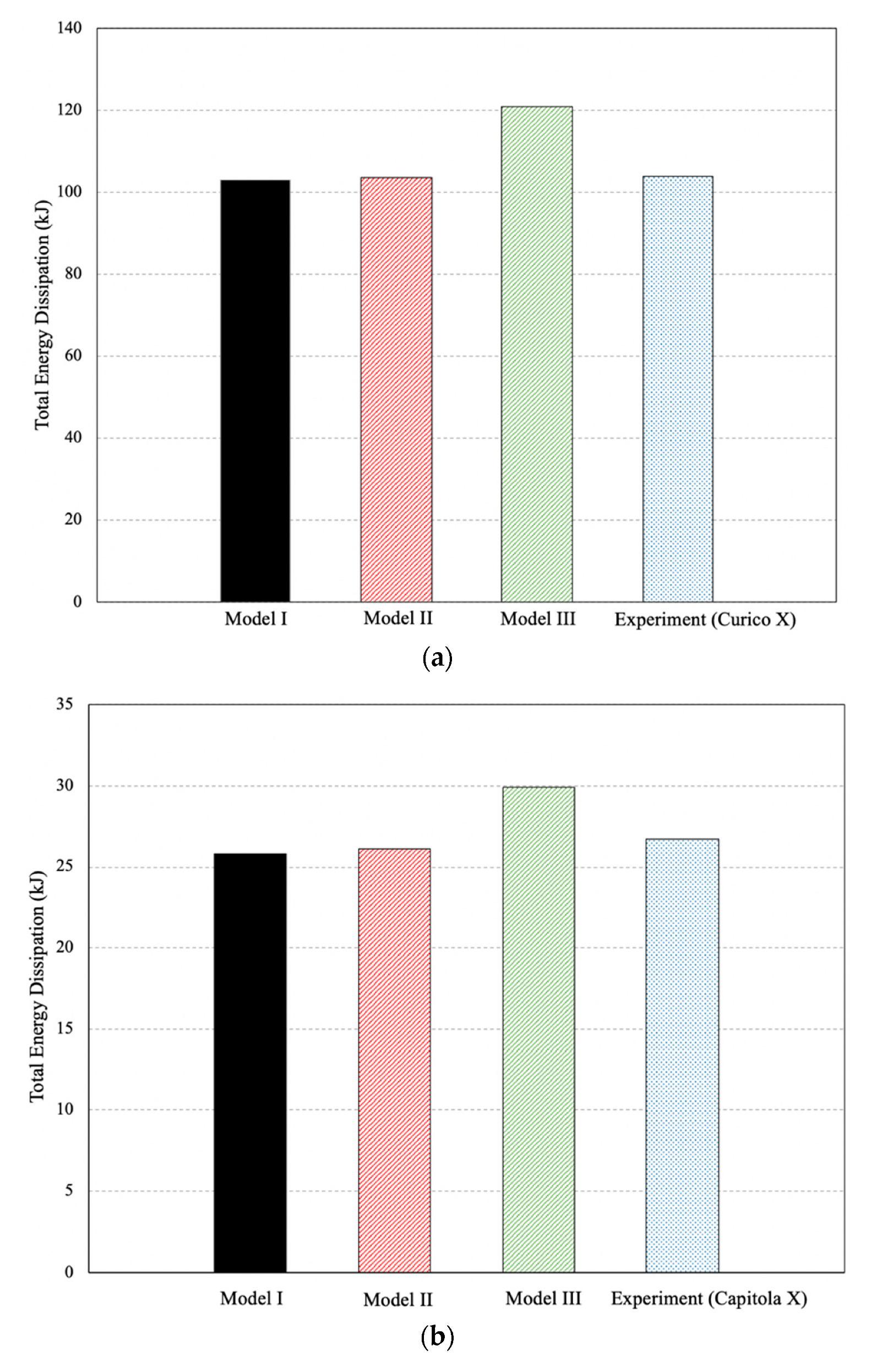
Figure 18 presents the total experimental dissipated energy contrasted to those obtained from the numerical models. The total energy dissipated was computed by summing the enclosed area from each cycle of the force-displacement hysteresis curve. Model III tends to overestimate the cumulative energy dissipated by the specimen by approximately 16% and 12% for the Curico X and the Capitola X records, respectively. This overestimation is primarily caused by the secondary moments (P-Δ effects) that the mass-rig transferred to the column. In contrast, Models I and II present a negligible overestimation in the total dissipated energy, with errors of 0.87% and 0.31% for the Curico X record, and 3% and 2% for the Capitola X record, respectively.
Since this study focused on implementing the proposed IMS to assess the seismic performance of large-scale bridge column models experimentally, it can be deduced from the results that test setups considering reduced-scale models could reproduce non-linear earthquake effects of real structural models. While extrapolating the behavior of the prototype model could be challenging when large-scale specimens are planned, the use of an external device on the specimen, such as the one proposed here, capable of accommodating large amounts of additional mass, can simulate the effects caused by earthquake inputs in real components, which is supported by the results.
6. Concluding Remarks
When large-scale models are evaluated using shake tables, large quantities of inertial masses must comply with proper representation requirements in terms of a fundamental period of the prototype structure and practical constraints imposed by the simulator capabilities. Two prominent experimental test setups for providing the necessary inertia during real-time dynamic tests were reviewed, focusing on cantilever column application. It was shown that a relatively simple and useful approach to add gravitational effects on the dynamic behavior of test models is to set the inertial mass directly on top of the specimen. However, safety issues and cost-effective set up considerations limit its utility especially when considering large test matrices. Although positioning the mass on an articulated supporting structure outside the shake table solves many of the shortcomings, secondary effects induced on the specimen are challenging to quantify.
A new inertial approach for performing dynamic testing using shake tables was developed and incorporated into evaluation of large-scale reinforced concrete bridge column specimens. Advantageous considerations included safety concerns for achieving near-collapse performance levels, limited out-of-plane displacements, decreased time for test preparation, and representative reproduction of P-Δ effects. To assess the effects of the proposed system on the force and stiffness of specimens, the equation of motion of the system was derived. Shake table tests of six substandard RC bridge column models were conducted validating the practicality and effectiveness of the proposed system. Furthermore, the proposed approach was compared numerically to two other popular systems. Numerical simulations showed that the proposed inertial mass system can reproduce seismic performance of cantilever columns as if the mass was mounted directly on the specimen’s top, which represents the ideal scenario for testing these types of structural component. Therefore, based on these results and the distinguished advantages, the proposed configuration can be effectively used as an inertial loading system for dynamic testing of reduced-scale models using shake tables.
Author Contributions
Conceptualization, P.D. and A.L.; methodology, A.L. and P.D.; validation, P.D. and A.L.; formal analysis, A.L.; investigation, A.L. and P.D.; writing—original draft preparation, A.L.; writing—review and editing, A.L. and P.D.; supervision, P.D.; funding acquisition, P.D. All authors have read and agreed to the published version of the manuscript.
Funding
This research was funded by the Oregon Department of Transportation (ODOT), grant number SPR 770 and The APC was funded by PUCV.
Institutional Review Board Statement
Not applicable.
Informed Consent Statement
Not applicable.
Data Availability Statement
The data presented in this study are available on request from the corresponding author. The data are not publicly available due to intellectual property.
Acknowledgments
The authors of this paper gratefully acknowledge funding support from the Oregon Department of Transportation (ODOT). The authors also thank the reviewers for their important comments. The first author also expresses his gratitude to the PUCV for financing the processing of this article.
Conflicts of Interest
The authors declare no conflict of interest.
References
- Pinho, R. Shaking Table Testing of RC Walls. ISET J. Earthq. Technol. 2000, 37, 119–142. [Google Scholar]
- Elwood, K.; Moehle, J.P. Shake Table Tests and Analytical Studies on the Gravity Load Collapse of Reinforced Concrete Frames; PEER Report 2003/01; University of Berkley: Berkeley, CA, USA, 2003. [Google Scholar]
- Deierlein, G.; Krawinkler, H.; Ma, X.; Eatherton, M.; Hajjar, J.; Takeuchi, T.; Kasai, K.; Midorikawa, M. Earthquake resilient steel braced frames with controlled rocking and energy dissipating fuses. Steel Constr. 2011, 4, 171–175. [Google Scholar] [CrossRef]
- Van de Lindt, J.W.; Pryor, S.E.; Pei, S. Shake table testing of a full-scale seven-story steel-wood apartment building. Eng. Struct. 2011, 33, 757–766. [Google Scholar] [CrossRef]
- Panagiotou, M.; Restrepo, J.I.; Conte, J.P. Shake-table test of a full-scale 7-story building slice. Phase I: Rectangular wall. J. Struct. Eng. 2011, 137, 691–704. [Google Scholar] [CrossRef]
- Schoettler, R.; Restrepo, J.; Guerrini, G.; Duck, D.; Carrea, F. A Full-Scale, Single-Column Bridge Bent Tested by Shake-Table Excitation; PEER Report 2015/02; University of Berkley: Berkeley, CA, USA, 2015. [Google Scholar]
- Carrillo, J.; Alcocer, S. Improved external device for a mass-carrying sliding system for shaking table testing. Earthq. Eng. Struct. Dyn. 2011, 40, 393–411. [Google Scholar] [CrossRef]
- Carrillo, J.; Gonzalez, G.; Llano, L. Evaluation of mass-rig systems for shaking table experiments. Dyna 2012, 79, 159–167. [Google Scholar]
- Lopez, A.; Dusicka, P.; Bazaez, R. Performance of seismically substandard bridge reinforced concrete columns subjected to subduction and crustal earthquakes. Eng. Struct. 2020, 207, 110216. [Google Scholar] [CrossRef]
- McKenna, F. OpenSees: A Framework for Earthquake Engineering Simulation. Comput. Sci. Eng. 2011, 13, 58–66. [Google Scholar] [CrossRef]
- Bairrao, R.; Vaz, C. Shaking table testing of civil engineering structures-The LNEC 3D simulator experience. In Proceedings of the 12th World Conference on Earthquake Engineering, Auckland, New Zealand, 30 January–4 February 2000; pp. 1–8. [Google Scholar]
- Mosalam, K.M.; Naito, C.J.; Khaykina, S. Bidirectional cyclic performance of reinforced concrete bridge column superstructure subassemblies. Earthq. Spectra 2002, 18, 663–687. [Google Scholar] [CrossRef]
- Sakai, J.; Jeong, H.; Mahin, S.A. Reinforced concrete bridge columns that re-center following earthquakes. In Proceedings of the 8th US National Conference on Earthquake Engineering, San Francisco, CA, USA, 18–22 April 2006; Volume 9, pp. 5270–5279. [Google Scholar]
- Ge, X.; Dietz, M.S.; Alexander, N.A.; Kashani, M.M. Nonlinear dynamic behaviour of severely corroded reinforced concrete columns: Shaking table study. Bull. Earthq. Eng. 2020, 18, 1417–1443. [Google Scholar] [CrossRef] [Green Version]
- Laplace, P.; Sanders, D.; Saiidi, M.S.; Douglas, B. Shake Table Testing of Flexure Dominated Reinforced Concrete Bridge Columns; Report CCEER99-13; Center for Earthquake Engineering Research, Department of Civil Engineering, University of Nevada: Reno, NV, USA, 1999. [Google Scholar]
- Chopra, A. Dynamic of Structures. Theory and Applications to Earthquake Engineering, 2nd ed.; Prentice-Hall: Englewood Cliffs, NJ, USA, 2001. [Google Scholar]
- Taucer, F.F.; Spacone, E.; Filippou, F.C. A Fiber Beam-Column Element for Seismic Response Analysis of Reinforced Concrete Structures; Report UCB/EERC-91/17; Earthquake Engineering Research Center, College of Engineering, University of California: Berkekey, CA, USA, 1991; Volume 138. [Google Scholar]
- Scott, M.H.; Fenves, G.L. Plastic hinge integration methods for force-based beam-column elements. J. Struct. Eng. 2006, 132, 244–252. [Google Scholar] [CrossRef]
- Berry, M.P.; Eberhard, M.O. Performance Modeling Strategies for Modern Reinforced Concrete Bridge Columns; PEER Report 2007/07; University of Berkley: Berkeley, CA, USA, 2008. [Google Scholar]
- Neuenhofer, A.; Filippou, F.C. Evaluation of nonlinear frame finite-element models. J. Struct. Eng. 1997, 123, 958–966. [Google Scholar] [CrossRef]
- Mander, J.B.; Priestley, M.J.N.; Park, R. Theoretical Stress-Strain Model for Confined Concrete. J. Struct. Eng. 1988, 114, 1804–1826. [Google Scholar] [CrossRef] [Green Version]
- Elwood, K.J.; Eberhard, M.O. Effective stiffness of reinforced concrete columns. ACI Struct. J. 2009, 106, 476–484. [Google Scholar]
- Ghannoum, W. Experimental and Analytical Dynamic Collapse Study of a Reinforced Concrete Frame with Light Transverse Reinforcement. Ph.D. Thesis, University of California, Berkeley, CA, USA, 2007. [Google Scholar]
- Mehary, S.; Dusicka, P.; Bazaez, R. Effect of Subduction Earthquake-Based Loading History on Substandard RC Square Columns. J. Bridg. Eng. 2018, 23, 04017146. [Google Scholar] [CrossRef]
Figure 1.
Research approach.

Figure 2.
Representation of an inertial mass without auxiliary-supporting structure.
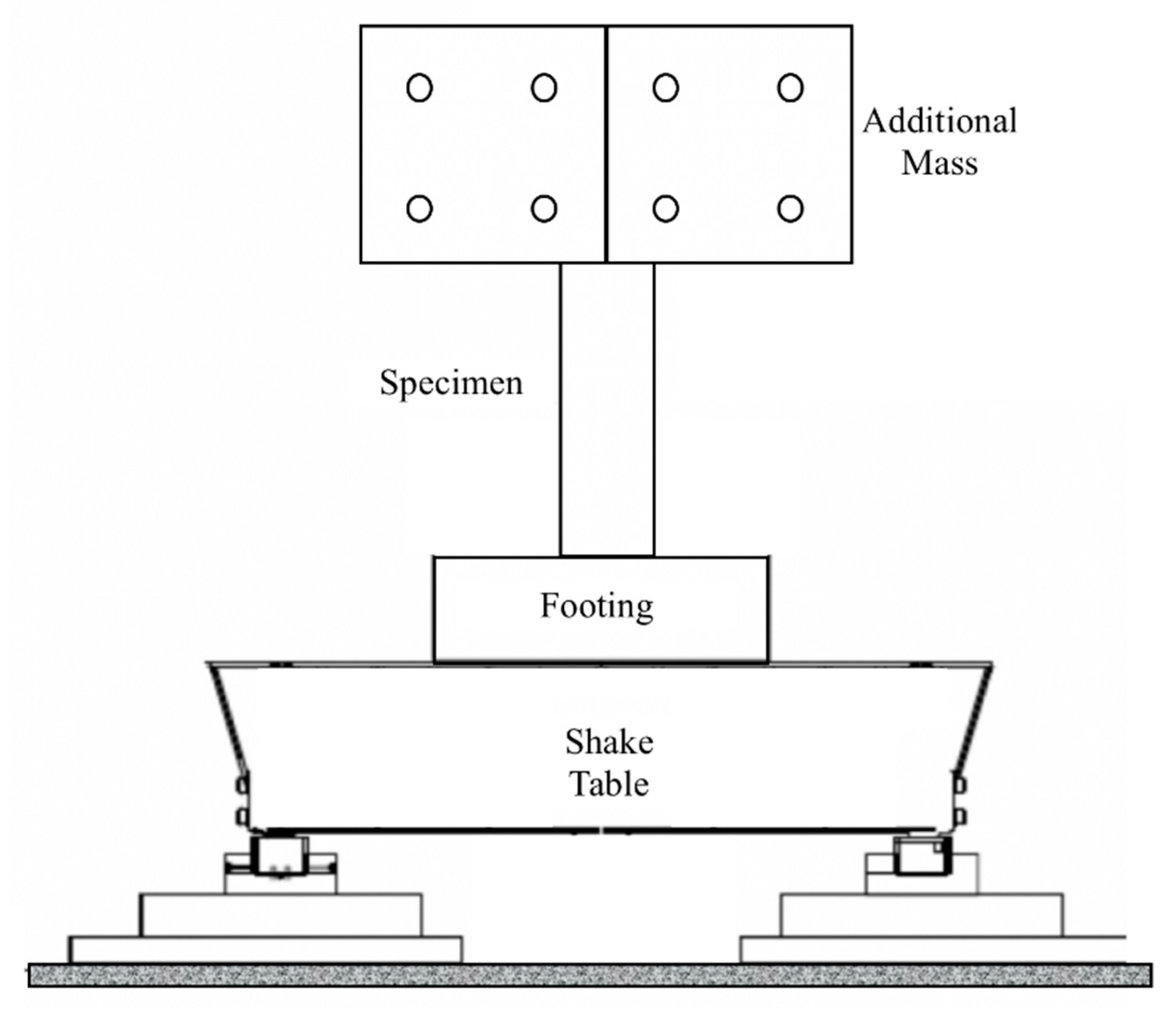
Figure 3.
Representation of an inertial mass with safety structure outside the shake table.

Figure 4.
Adapted representation of a rotational system for supporting additional inertial mass.
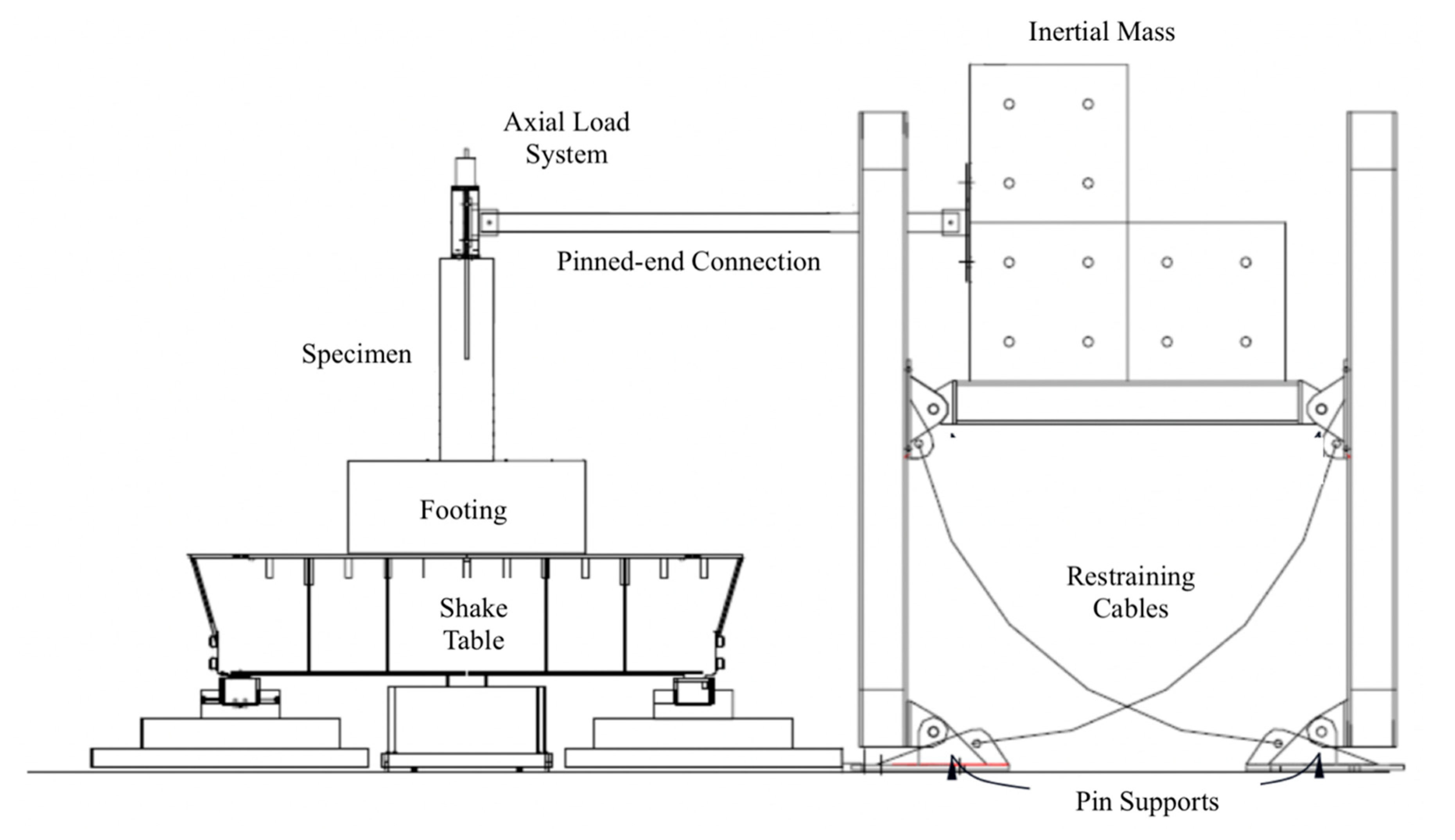
Figure 5.
Schematic of the inertial mass system (IMS) part of test setup: (a) 3D view; (b) South view.
Figure 5.
Schematic of the inertial mass system (IMS) part of test setup: (a) 3D view; (b) South view.
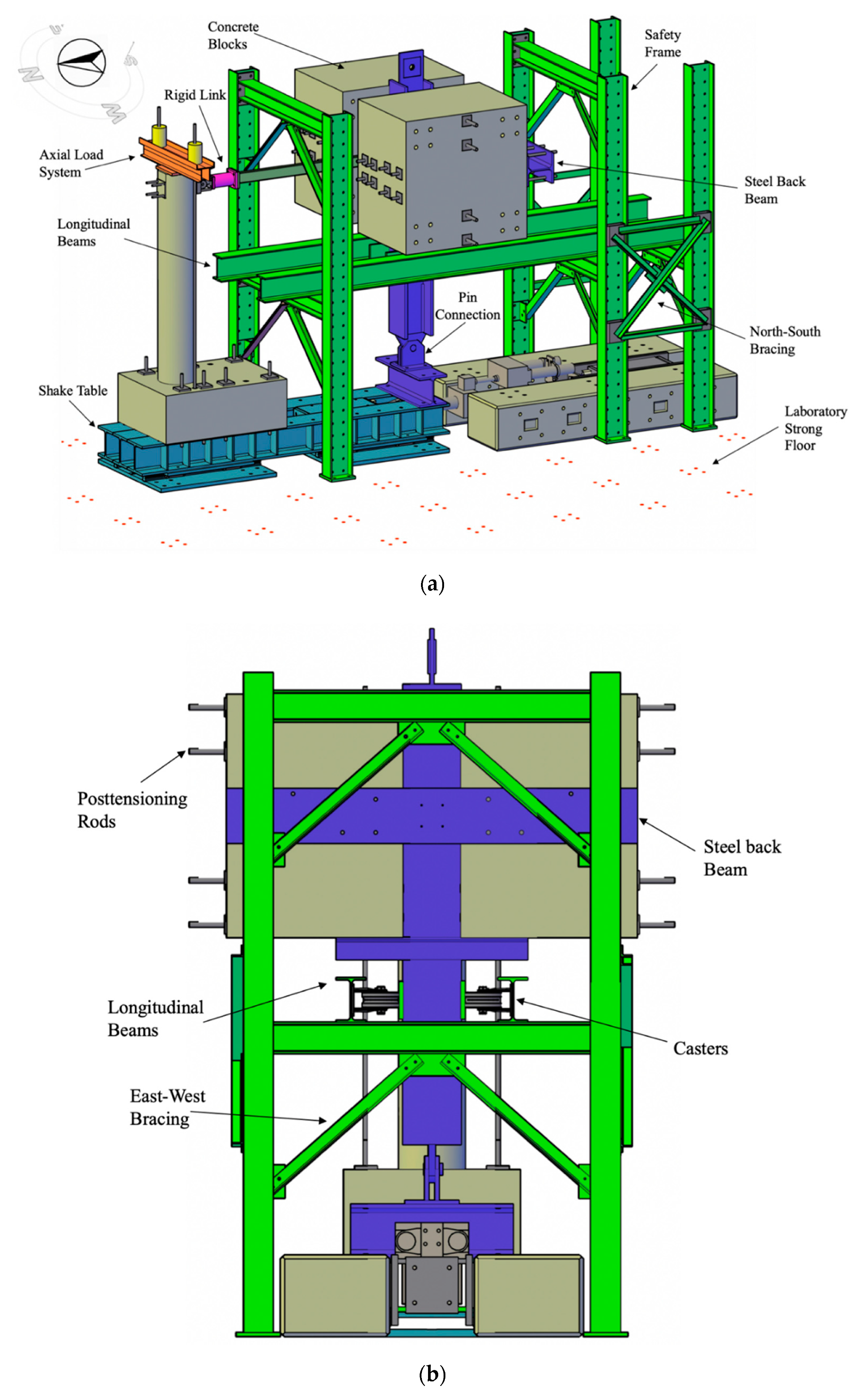
Figure 6.
IMS assembly process.

Figure 7.
IMS reaching the maximum displacement limit under specimen collapse.
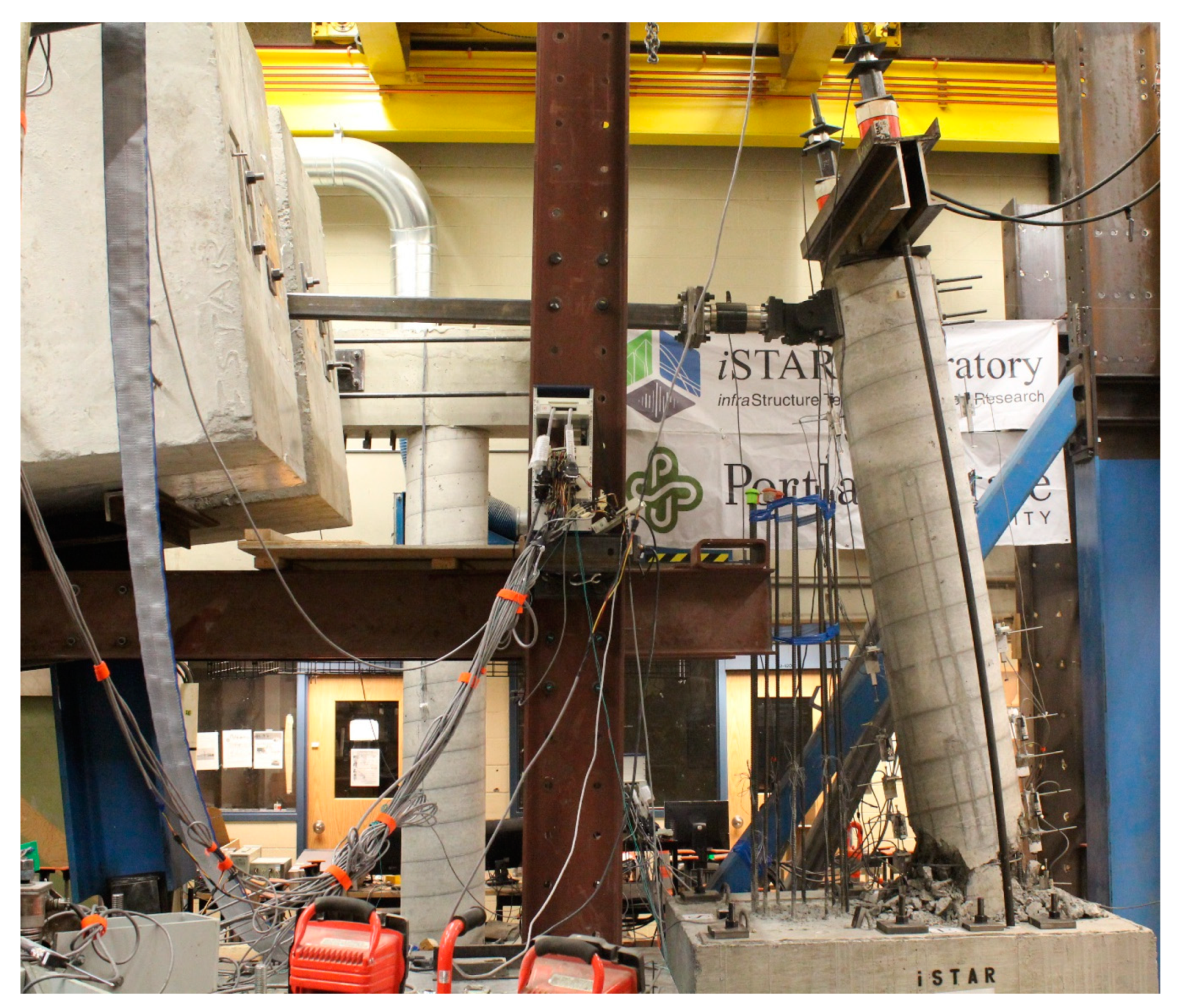
Figure 8.
IMS mass locations.

Figure 9.
P-Δ effect due to the axial load.
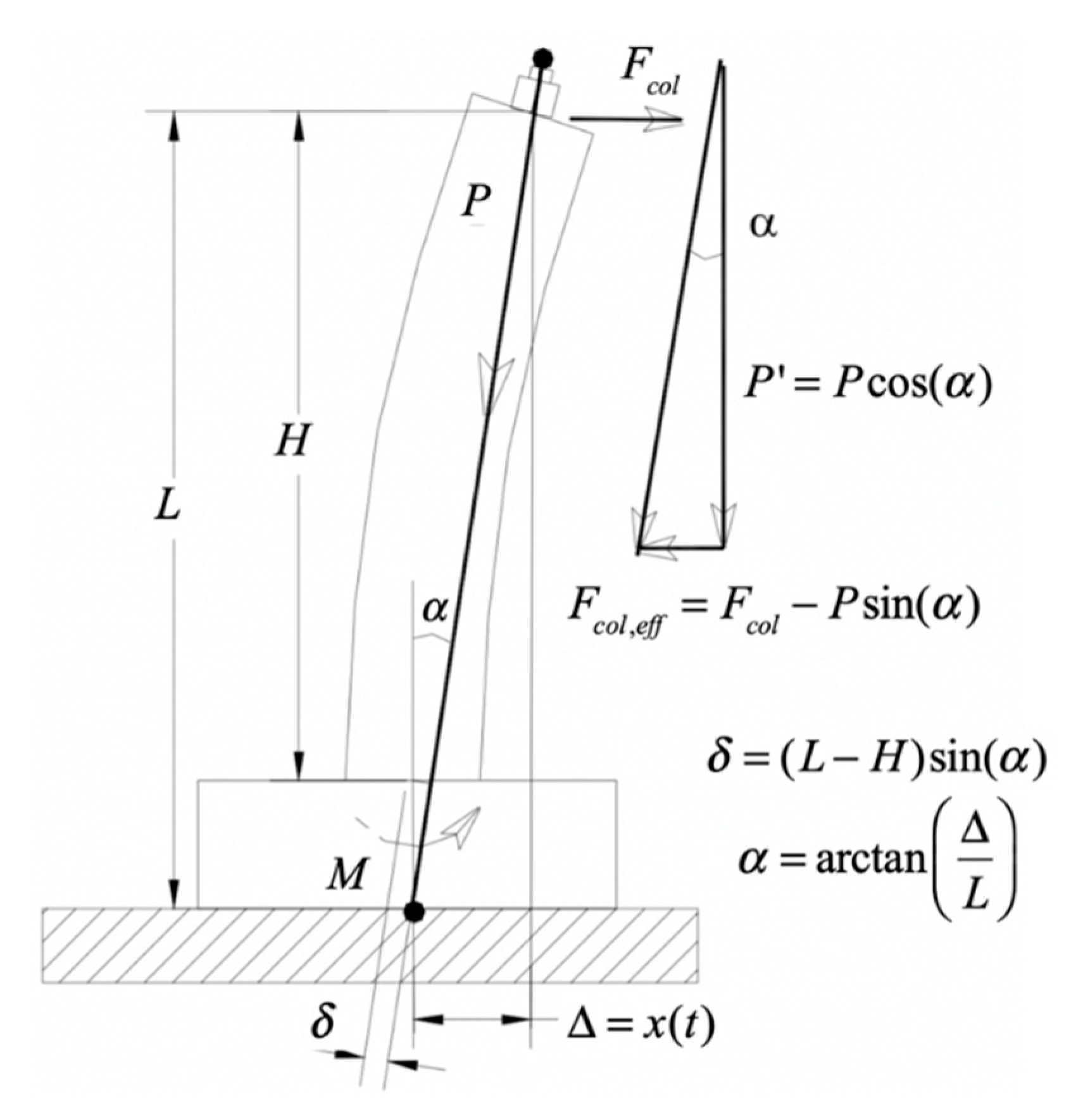
Figure 10.
Cross-section of the reinforced concrete (RC) column model.
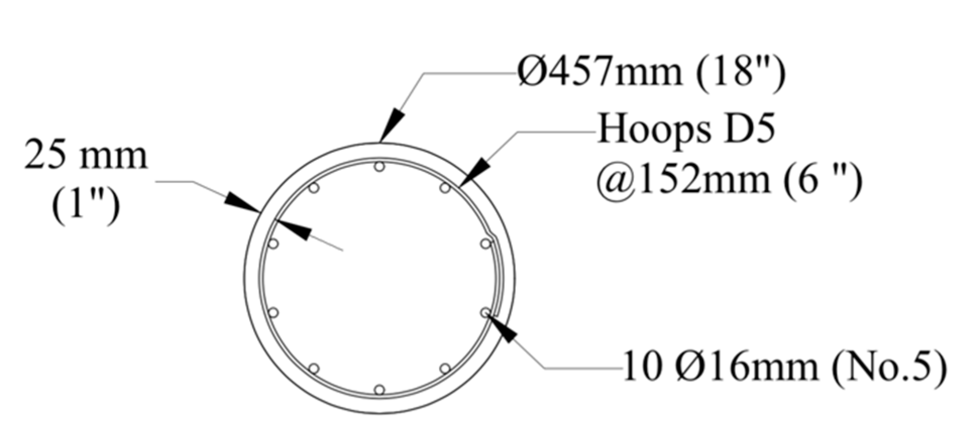
Figure 11.
Time histories for the Curico X (top) and Capitola X record (bottom): (a) Acceleration; (b) Displacement.
Figure 11.
Time histories for the Curico X (top) and Capitola X record (bottom): (a) Acceleration; (b) Displacement.

Figure 12.
Model I.
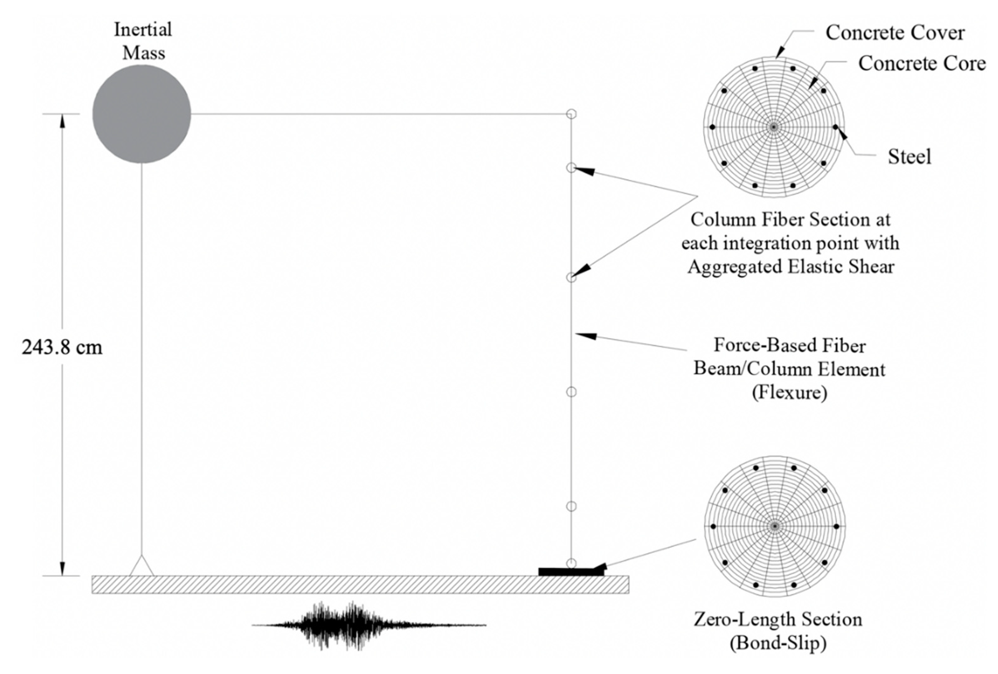
Figure 13.
Fiber stress-strain relations: (a) steel; (b) concrete.

Figure 14.
Model II.

Figure 15.
Model III.
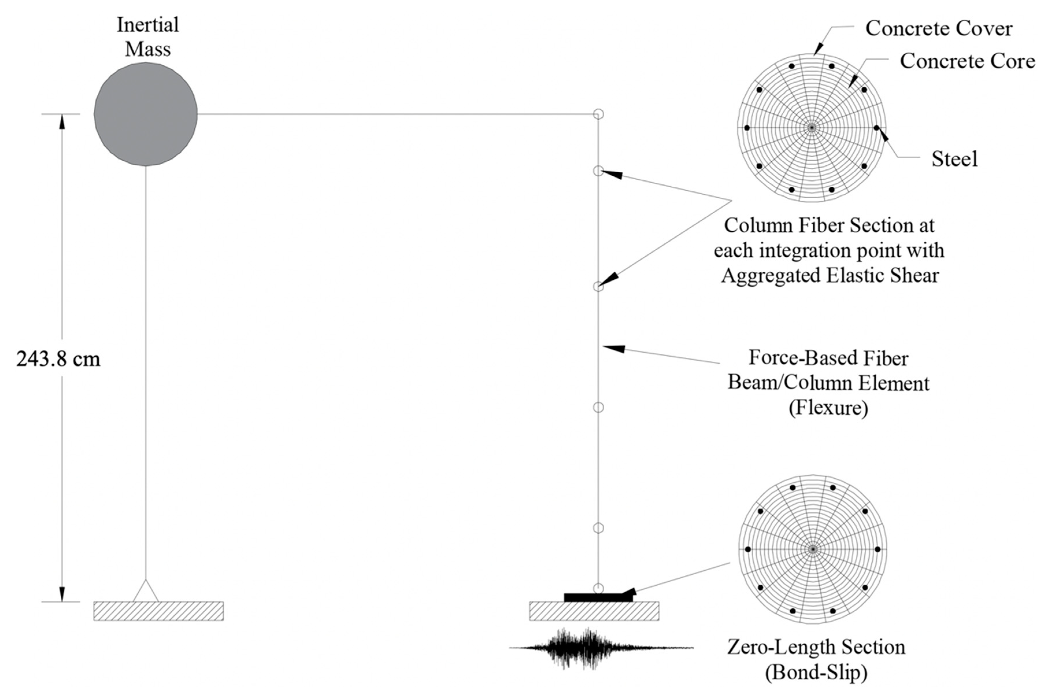
Figure 16.
Column displacement histories comparison: (a) Curico X record; (b) Capitola X record.
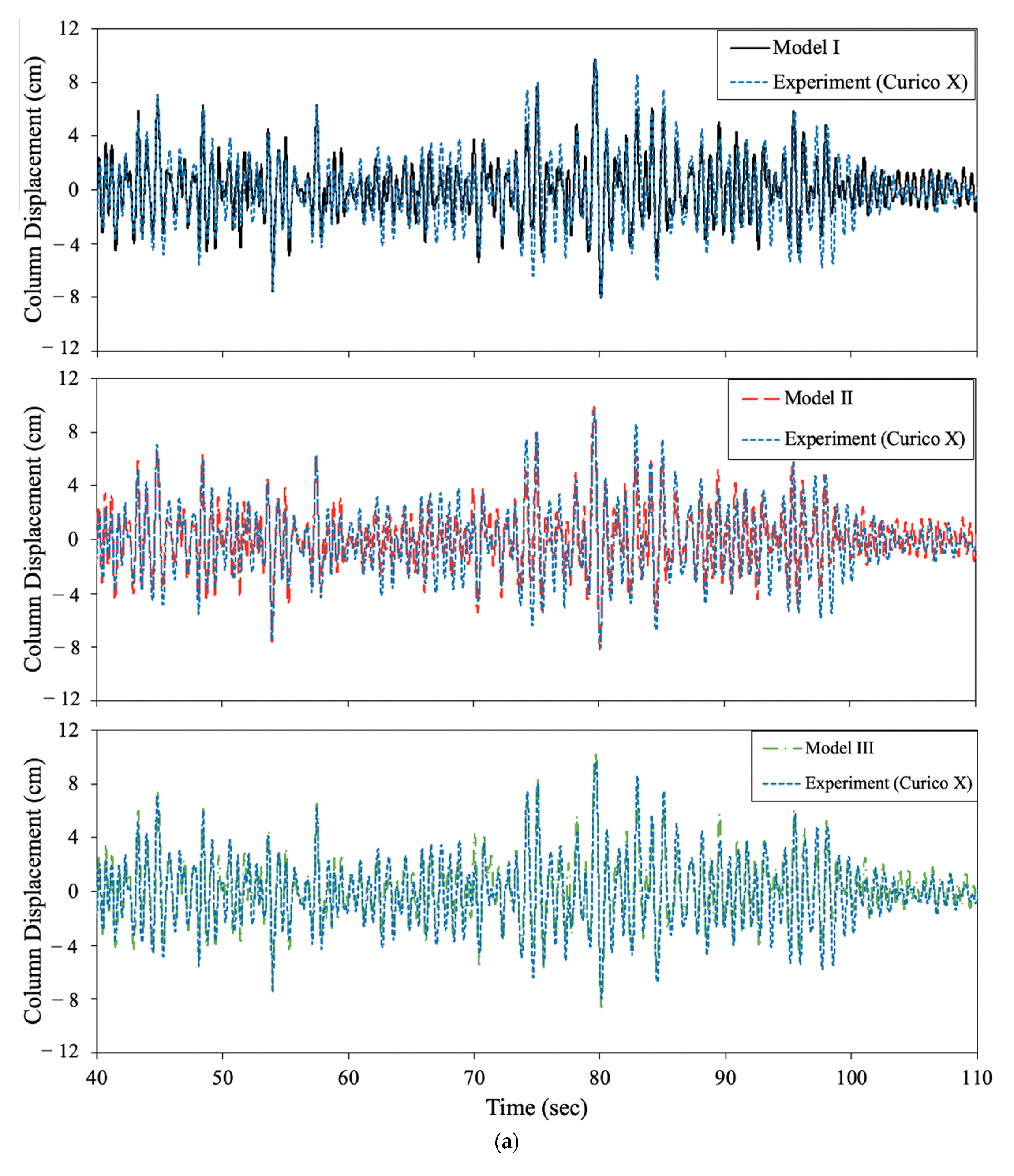
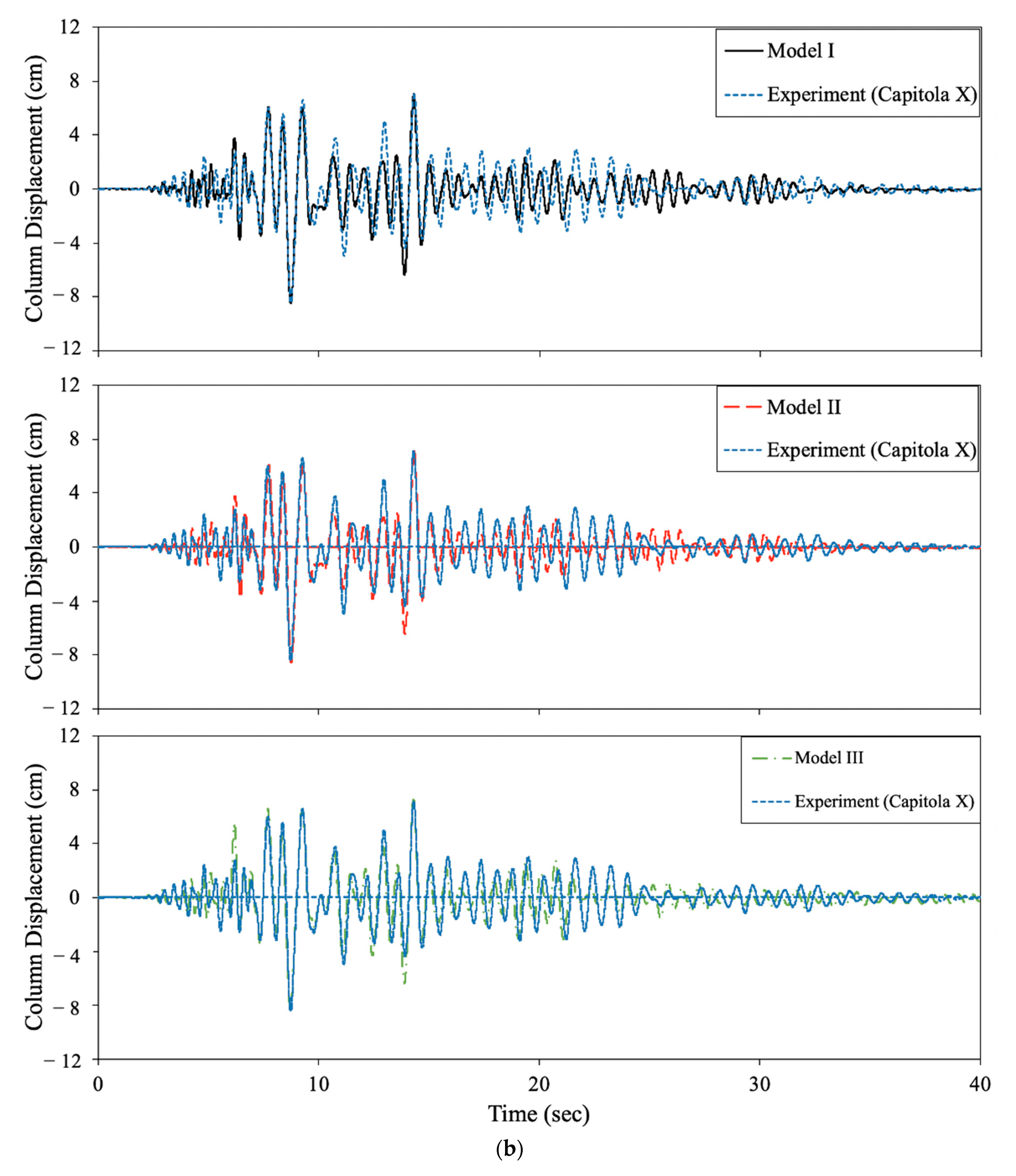
Figure 17.
Force-displacement hysteresis comparison: (a) Curico X record; (b) Capitola X record.

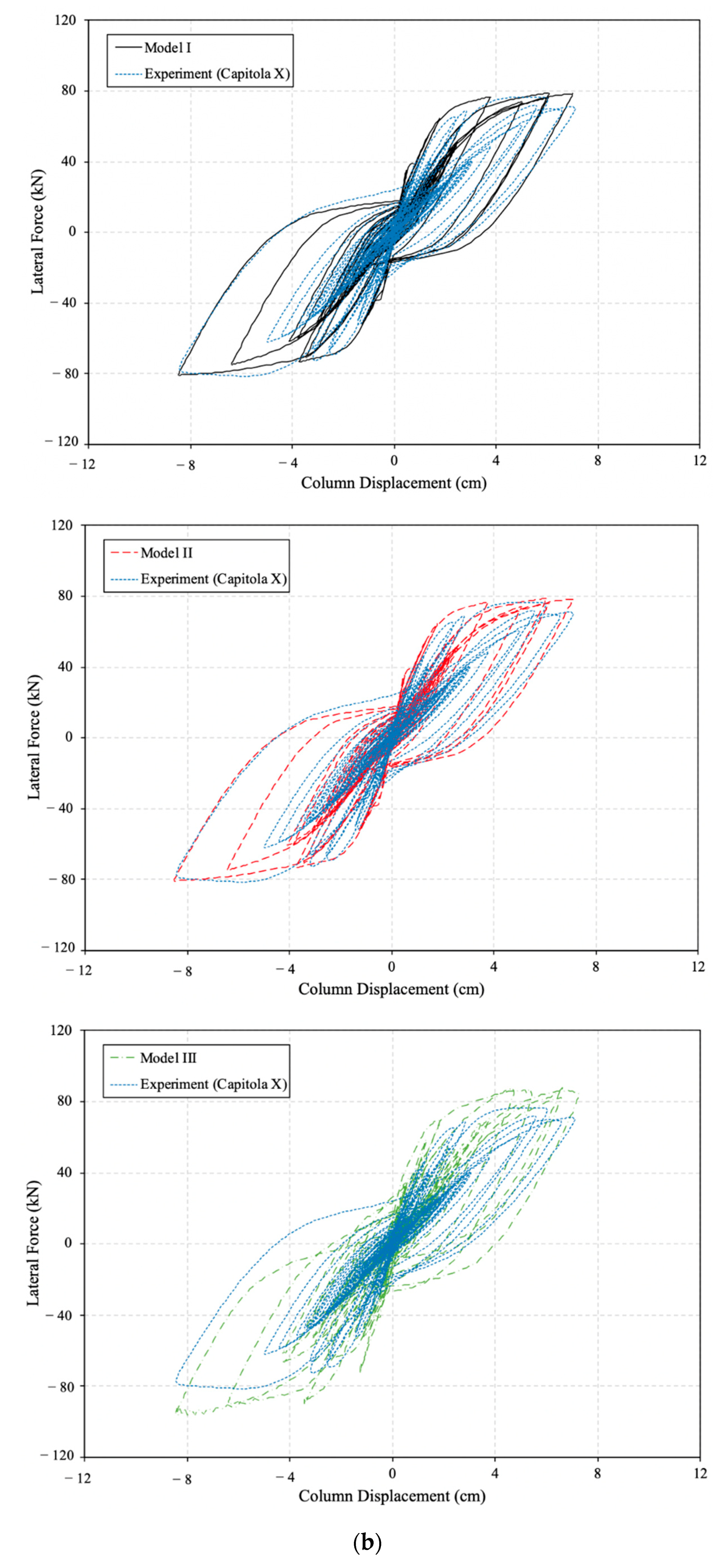
Figure 18.
Energy dissipation comparison: (a) Curico X record; (b) Capitola X record.

Table 1.
Masses and dynamic weights of the IMS.
| Component | Mass (kg) | Weight (kN) |
|---|---|---|
| m1 = concrete blocks, W-beam, portion of steel column mass | 20,636 | 202.4 |
| m2 = rigid link system | 136 | 1.3 |
| m3 = axial load system | 236 | 2.3 |
| m4 = distributed mass of specimen contributing to effective inertia | 1061 | 10.4 |
| ψ1 | 0.22 | |
Publisher’s Note: MDPI stays neutral with regard to jurisdictional claims in published maps and institutional affiliations. |
© 2021 by the authors. Licensee MDPI, Basel, Switzerland. This article is an open access article distributed under the terms and conditions of the Creative Commons Attribution (CC BY) license (http://creativecommons.org/licenses/by/4.0/).
Share and Cite
MDPI and ACS Style
Lopez, A.; Dusicka, P. Implementation of a Novel Inertial Mass System and Comparison to Existing Mass-Rig Systems for Shake Table Experiments. Appl. Sci. 2021, 11, 692. https://doi.org/10.3390/app11020692
AMA Style
Lopez A, Dusicka P. Implementation of a Novel Inertial Mass System and Comparison to Existing Mass-Rig Systems for Shake Table Experiments. Applied Sciences. 2021; 11(2):692. https://doi.org/10.3390/app11020692
Chicago/Turabian StyleLopez, Alvaro, and Peter Dusicka. 2021. "Implementation of a Novel Inertial Mass System and Comparison to Existing Mass-Rig Systems for Shake Table Experiments" Applied Sciences 11, no. 2: 692. https://doi.org/10.3390/app11020692
Note that from the first issue of 2016, this journal uses article numbers instead of page numbers. See further details here.