A Dual-Band Modified Franklin mm-Wave Antenna for 5G Wireless Applications
by
 , , , and
Arjun Surendran
1 ,
,
Aravind B
1, 
Tanweer Ali
1,* ,
,
Om Prakash Kumar
1 ,
,
Pradeep Kumar
2,* and
Jaume Anguera
3,4 
1
Department of Electronics and Communication, Manipal Institute of Technology, Manipal Academy of Higher Education, Manipal 576104, India
2
Discipline of Electrical, Electronic and Computer Engineering, University of KwaZulu-Natal, Durban 4041, South Africa
3
Fractus Antennas, 08174 Barcelona, Spain
4
Electronics and Telecommunication Department, Universitat Ramon LLull, 08022 Barcelona, Spain
*
Authors to whom correspondence should be addressed.
Appl. Sci. 2021, 11(2), 693; https://doi.org/10.3390/app11020693
Submission received: 13 December 2020
/
Revised: 4 January 2021
/
Accepted: 5 January 2021
/
Published: 12 January 2021
(This article belongs to the Special Issue New Trends in Telecommunications Engineering)
Abstract
:Franklin array antennas are considered as one of the most competitive candidates for millimeter-wave (mmW) 5G applications due to their compact size, simple geometry and high gain. This paper describes a microstrip Franklin antenna array for fifth generation (5G) wireless applications. The proposed modified Franklin array is based on a collinear array structure with the objective of achieving broad bandwidth, high directivity, and dual-band operation at 22.7 and 34.9 GHz. The designed antenna consists of a 3 × 3 array patch element as the radiating part and a 3 × 3 slotted ground plane operating at a multiband resonance in the mmW range. The dimensions of the patch antennas are designed based on λ/2 of the second resonant frequency. The designed antenna shows dual band operation with a total impedance bandwidth ranging from 21.5 to 24.3 GHz (fractional bandwidth of 12.2%) at the first band and from 33.9 to 36 GHz (fractional bandwidth of 6%) at the second band in simulation. In measurement, the impedance bandwidth ranges from 21.5 to 24.5 GHz (fractional bandwidth of 13%) at the first band and from 34.3 to 36.2 GHz (fractional bandwidth of 5.3%) at the second band, respectively. The performance of the antenna is analyzed by parametric analysis by modifying various parameters of the antenna. All the necessary simulations are carried out using HFSS v.14.0.
1. Introduction
The evolution of mobile standards from the first generation (1G) standard to the fifth generation (5G) standard, where we currently stand, and the future standards is considered as a revolution in the field of wireless communications. It all began with 1G, where the basic calling facility was introduced with no proper coverage and security for the network. 2G networks changed the whole concept with the introduction of a messaging facility or short message system as well as with digital voice calls and encryption of the calls. The second-generation network laid the foundation for all wireless communication networks. The introduction of 3G, or the packet-switched networks improved data rates, increased data transfer capability, as well as the introduction of video calls for applications such as video streaming and video conferencing revolutionized the mobile standards [1]. Fourth-generation (4G) networks are currently the most popular network standard in the present world. The transition from the previous standard to the present standard required various infrastructure changes to the antenna as well as the other equipment such that it can become 4G compatible. All the above standards face a common problem, which is the scarcity of bandwidth. The 5G standard or the internet of things era is the solution that overcomes this problem. 5G technology requires new infrastructure that has to be laid for the implementation. It is a mature technology that has proven to be of high data rate communication [2,3].
The wireless spectrum that exists presently is losing its free space, which has led to researchers exploring the unused millimeter-wave (mmW) spectrum for such applications [4]. Millimeter wave technology exploits the frequency spectrum from 30 to 300 GHz. The wavelength required for the operation of mmW varies from 10 to 1 mm. The advantages of using the above technology include high data rates, almost the same as those obtained in optical fibers, achieved at a lesser cost or free of cost [5,6]. The added merits to this technology are that at high frequencies, the traffic is less, and the communication would be more secure because these frequencies cannot be utilized by everyone. The drawbacks are that a completely modified infrastructure has to be laid out for obtaining these higher frequencies [7,8]. Proper substrate selection is needed with an appropriate value of dielectric constant, while the thickness of the substrate also plays an important role in the deployment of this technology.
mmW technology deals with frequencies in the range of GHz, so the conventional single-antenna structures might fall short of the requirements such as high gain, directive patterns, and bandwidth. So, the need of combining of antenna structures to form array structures is required. Among the different types of antenna array structures, one of the array types is the collinear array (CoA) antenna. A series of antenna elements that are fixed in such a manner that they are parallel and located along a common axis is termed a collinear antenna array. This antenna principle is further modified and applied to a new antenna termed Franklin antenna [9]. In a Franklin array antenna, in addition to the antenna patch elements that are placed in a collinear manner, two transmission lines are placed in between the patches as well as a phasing stub assembly. High gain is a feature of these antennas. The restriction of these classes of antennas is that they are mainly restricted to a single band of operation [9,10,11].
Several researchers showed interest in the collinear array principle of antennas in improving the various antenna parameters. A simple arrangement of collinear microstrip patch antenna is illustrated in [12,13], which was limited to a single band operation with a high gain. The narrowband, along with single-band operation, was the limitation of this antenna. Various modifications of the collinear array antenna were introduced, of which the Franklin antenna is an example. Researchers have worked on several modifications of this antenna to obtain improved antenna parameters. One such work is demonstrated in [14], where it is used for radar application. Here, the conventional Franklin antenna is modified for automotive short-range radar applications in which the phase-shifting sections are arranged in a simple straight-line configuration. It is again restricted to a single band operation with less bandwidth. Another variation of the Franklin antenna is presented in [15], which is used for wireless charging applications. The design is complex, as it consists of 32 elements arranged in a collinear array pattern. Since it is designed for wireless charging applications, the frequency of operation is low. A 14 element Franklin antenna was proposed in [16]. The advantage of this design was that a simplified feeding technique was introduced, which gave rise to a more longitudinally and transversely compact class of antennas. A circularly polarized Franklin antenna is demonstrated in [17], where it finds its application in radars. Here the 12 elements are arranged circularly to obtain a circular class of Franklin antenna. The design provides high inter port isolation and moderate impedance. All these antennas were limited to narrowband operation, and in [18], a modified Franklin antenna was introduced where the upper and lower cut off frequencies are designed based on the patch length and stub length. The six-element array antenna generated a wide bandwidth over a single resonant frequency. In [19], the Franklin antenna was developed on dielectric slab to operate at single band of operation. Here, the meander-based geometry is used to obtain high impedance phenomenon at the desired single band resonance. The designed antenna is powered by standard and surface waves along with a dielectric structure, in such a way that the energy is gradually radiated. Finally, in [20], the design that was used for the multi-band response was modified to obtain a single band operation. The design was modified in such a way that additional uniform slots were introduced in the ground plane. This enabled the antenna to resonate at a single frequency with a suitable bandwidth. Even though this antenna results in a large bandwidth as well as gain, the drawback was that it was limited to a single frequency of operation.
All of the collinear array antennas and Franklin antennas that were designed earlier faced certain drawbacks, such as the single/dual resonant frequency with narrowband operation, limited bandwidth, low directive pattern, and complex structure. Due to these issues, it may be difficult for them to be integrated with portable wireless devices for modern wireless communication systems. In this paper, the proposed antenna introduces the concept of a Franklin antenna that has been modified in such a way to obtain a wideband antenna resonating at two different frequencies i.e., 22.7 and 34.9 GHz. The proposed antenna is designed in four steps. In the first step, the Franklin radiator is designed by utilizing a 3 × 3 unit cell array structure with full ground plane. This structure resulted in four mmW bands with poor impedance matching at the first three bands. So, in order to overcome this problem, the ground plane is etched with a one-by-three array slot format in the second step. This modification also resulted in triple band operation but with poor impedance matching at the first two bands. In the third step, the slot configuration at the ground part is modified in the form of a two-by-three array, while keeping the radiator unchanged. This configuration resulted in dual band operation with S11 very close to −10 dB, at both bands. Finally, in the fourth step, in order to get the desired wide bandwidth and good impedance matching with dual band operation (i.e., at 22.7 and 34.9 GHz), the ground part is further etched with a slot configuration of a three-by-three array. A detailed parametric investigation is also carried out to fix the dimension of the proposed design. The main advantage of the antenna is that the aforementioned modifications are introduced into the radiating part and ground plane in such a manner that there is no additional increase in the area of the antenna, i.e., the antenna remains compact.
2. Antenna Design Approach
2.1. Proposed Antenna Configuartion and Dimension Layout
The final antenna or the proposed antenna with detailed optimized dimensions is shown in Figure 1. The antenna has a 3 × 3 array-like structure, which consists of 9 patch elements, of which six of these patch elements have a dimension of PL × PW. Three of them have a dimension of (PL + R) × PW. Each row of these patch elements also has folded dipole elements that connect the row-wise patch elements. The antenna feeding network is provided to the last row of the patch elements. The ground plane consists of nine slots that are etched in a 3 × 3 manner to provide the required response. The last cut in the first column of the array follows a slight misalignment to obtain the proper response with an appropriate gain required for proper operation. The detailed dimensions of the antenna are shown in Table 1. The antenna designed in this paper is based on the concept of [7,11,18,20].
The proposed modified Franklin array structure is based on a collinear array structure. A set of patches and stubs constitutes a collinear array structure. The modified Franklin array structure consists of 9 patch antennas arranged in a 3 × 3 configuration, and in between each row of these patches contains stubs that have been changed to symmetrically folded dipole like structures, as illustrated in Figure 1. These 9 patch antennas and folded dipole-like structures arranged in a 3 × 3 array manner are connected to a feeding network that has been modified into a folded dipole like structure and connected from the last row of patch antennas and folded dipole like structures.
The patch antennas are of dimensions PL × PW. The six patch antennas in the second and third row of the array follow these dimensions. The first row of patch antennas has an incremental length R added to it. The dimensions of the patch antennas are designed based on λ/2 of the second resonant frequency. Similarly, in an arrangement similar to the 3 × 3 arrangement of patch elements, modifications are made to the ground in a 3 × 3 manner to the original design such that the desirable dual-band operation of the antenna is achieved.
HFSS, or High-Frequency Structure Simulator software, is used in the modeling, simulation, and analysis, as well as for the numerical evaluation of the antenna design. The substrate used had a height (h) of 0.8 mm, and a metallic ground was used at the bottom.
2.2. Design Steps to Obtain the Proposed Antenna
In this section, the procedure to obtain the final antenna is described in detail. The proposed Franklin antenna array is designed in four steps. Initially, the first antenna is designed with a full ground plane at the bottom of the substrate and the top portion of the substrate consisting of the patch consisting of a 3 × 3 array of a unit cell. This antenna is termed as antenna M. The representation of the antenna structure is shown in Figure 2a,b. This antenna shows a quad band of operation at 24.4, 25.8, 26.6 and 32.7 GHz with very poor impedance matching at the first three bands.
So, to improve the impedance matching in the initial antenna M, in the next step, slots are introduced in the ground plane. This antenna is now termed antenna N. The representation of the antenna structure is shown in Figure 3a,b, wherein it can be seen that three cuts are made in the ground plane. Two cuts are of dimensions WG × LG, and one cut is of dimensions WC × LG. The last column’s squares are made with different sizes and are not of the same dimensions as the other squares, in order to make the antenna resonate at a particular frequency. This modification also leads to a triple band of operation at 22.5, 24.9 and 35.3 GHz, with very poor impedance matching at the last two bands.
To further improve the performance of the designed antenna N, in the next stage an additional three slots are etched to the ground part. This modified antenna is now termed antenna O. The representation of this antenna structure is shown in Figure 4a,b. The slots are now of a 2 × 3 array form. The new row of slots formed consists of two cuts of dimensions WG × LC and one cut of dimensions WC × LC. The last cut that lies close to the boundary of the ground is slightly misaligned to the cut made in the previous stage for obtaining a proper response. This modification allows the antenna to operate at dual-band i.e., at 22.6 and 35.05 GHz, with a lower reflection coefficient value at both the bands.
To further improve the impedance matching at the dual band, the final modifications are made to the ground part of antenna O by etching one more row of square slots, thereby resulting in 9 cuts in the ground plane. The introduction of these slots further affect the surface current behavior of the antenna, thereby improving the impedance matching of the antenna. This antenna is now termed as P (proposed antenna). The representation of the antenna structure is shown in Figure 5a,b. The cuts that were introduced in the ground plane are in the form of a 3 × 3 array structure. The last row of cuts formed consists of two cuts of dimensions WG × LC and one cut of dimensions WC × LC. The last cut that lies close to the ground’s boundary is slightly misaligned to the cut made in the first stage and aligned to the cut made in the previous stage for obtaining a proper frequency response for the required dual-band operation. Thus, one of the cuts in the final proposed antenna is misaligned to the other cuts of the same column. The reflection coefficient of the antenna’s various stages is illustrated in Figure 6. It can be observed that the antenna offers a dual-band operation at 22.7 and 34.9 GHz with excellent impedance matching at both the bands. Thus, it can be concluded that the slots are added to the ground plane for the antenna to radiate at the particular frequencies and improve the input impedance matching and S11.
3. Parametric Analysis
A parametric study analyzes the patch element’s impact, and the slots etched in the ground plane on the antenna. The design’s performance is mainly influenced by the incremental length (R), the patch element length (PL), the length and width of the slots in the ground plane LG, LC, WG, WC.
3.1. Effect of Length of Patch Element PL
The effect of the length of the patch element on the antenna is studied. The length of the element is increased to analyze its effect. The increase in the length causes a variation in the resonant frequency as well as the return loss of the antenna. The variation of the length of patch PL is shown in Figure 7.
3.2. Effect of Incremental Length R
The effect of the incremental length of the patch elements of the first row on the antenna is analyzed. The length is varied to analyze its effect. The variation in the length does not cause a significant variation in the resonant frequency, but a very significant variation in the antenna’s return loss is seen. The variation of the incremental length R is demonstrated in Figure 8.
3.3. Effect of the Width of the First Type of Ground Cut WG
The effect of the width of the first type of ground cut on the antenna is studied. The width is varied to study its impact. The variation in the width causes a significant variation in both the resonant frequency, but a very substantial variation in the antenna’s return loss is observed at the first resonant frequency. At the second variation, not much change is observed in terms of return loss. The variation of the width of the first type of ground cut WG is given in Figure 9.
3.4. Effect of the Width of the Second Type of Ground Cut WC
The effect of the width of the second type of ground cut on the antenna is analyzed. The width is varied to observe its impact. The variation in the width causes a significant variation in both the return loss and frequency at the first resonant frequency. In contrast, at the second frequency, the return loss and frequency changes are small. The variation of the width of the second type of ground cut WC is shown in Figure 10.
3.5. Effect of Length of First Type Ground Cut LG
The effect of the width of the first type of ground cut on the antenna is studied. The width is varied to study its impact. The increase in the length results in variation in return loss at both frequencies, whereas the resonant frequency shifts at the first resonant value. The decrease in the length does not have a significant effect on the first resonant frequency. Still, at the second resonant frequency, both the frequency and return loss values are significantly changed. The variation of the length of the first type of ground cut LG is given in Figure 11.
3.6. Effect of Length of Second Type Ground Cut LC
The effect of the width of the second type of ground cut on the antenna is analyzed. The length is varied to observe its impact. The variation in the length does not significantly affect the frequency, but it results in a considerable variation in the return loss values at both resonant frequencies. The variation of the length of the second type of ground cut LC is given in Figure 12.
4. Results and Discussion
In the proposed design, the primary array antenna consists of a modified Franklin array structure printed on a substrate, which is of the material Rogers RT/duroid 6010, having a relative permittivity of 10.2 and a loss tangent of 0.0023. The simulation and measurement results for the S11 parameter vs. frequency of the antenna is depicted in Figure 13. The S11 result of the proposed antenna is measured using Anritsu 37269 A Vector Network Analyzer. It can be seen from the figure that the resonant frequency occurs for two values of operating frequency; 22.7 and 34.9 GHz in simulation, and at 22.8 and 35.3 GHz in measurement. In the simulation, for the first resonant frequency (i.e., 22.7 GHz), a bandwidth (for S11 < −10 dB criteria) of 2.8 GHz (21.5–24.3 GHz) and fractional bandwidth of 12.25% with maximum S11 of −30 dB is observed, and for the second resonant frequency (i.e., 34.9 GHz), a bandwidth of 2.1 GHz (33.9–36 GHz) and fractional bandwidth of 6% with maximum S11 of −23 dB is obtained. During measurement, for the first resonant frequency (i.e., 22.8 GHz), a bandwidth of 3 GHz (21.5–24.5 GHz) and fractional bandwidth of 13% with maximum S11 of −32 dB is observed, and for the second resonant frequency (i.e., 35.3 GHz), a bandwidth of 1.9 GHz (34.3–36.2 GHz) and fractional bandwidth of 5.3% with maximum S11 of −22 dB is obtained. Figure 13 clearly shows that the proposed structure achieves good impedance matching at both bands and the simulated and measured results are in close agreement.
The surface current distribution patterns for the proposed antenna are analyzed in Figure 14 for both resonant frequencies. At 22.7 GHz, the maximum currents can be observed at the second and third arm from the left, while the corner of the ground creates more significant discontinuity to the flow of current at this band, as demonstrated in Figure 14a. At 34.9 GHz, the current leakage is more from the antenna’s first and third arm from the left. Simultaneously, the slots in the ground allow more discontinuity in the current flow, thereby increasing the total current length path covering this particular band, as demonstrated in Figure 14b.
The 3D total gain pattern for the proposed antenna at both the resonant frequencies is shown in Figure 15. It is observed that the desired configuration of the antenna produces a maximum gain of 7.8 dB for 22.7 GHz and a gain of 9.7dB for 34.9 GHz. The gains are reasonably good as the bandwidth obtained at this band is relatively wide.
The variation of gain with frequency for the bandwidth of operation for the two resonant frequencies is analyzed, as shown in Figure 16. At the first band, i.e., 22.7 GHz, the gain is nonlinear and may be due to the dimension tuning of slots at ground plane to obtain the desired band. However, at the second band, i.e., 34.9 GHz, the gain varies linearly over the entire resonant bandwidth. The variation of radiation efficiency over the entire operating bandwidth for the two operating bands (i.e., 21.5–24.3 GHz, and 33.9–36 GHz) is also depicted in Figure 16c,d, respectively. It can be noticed that the antenna has radiation efficiency greater than 90%, at both the operating bandwidth, thus ensuring effective radiated power.
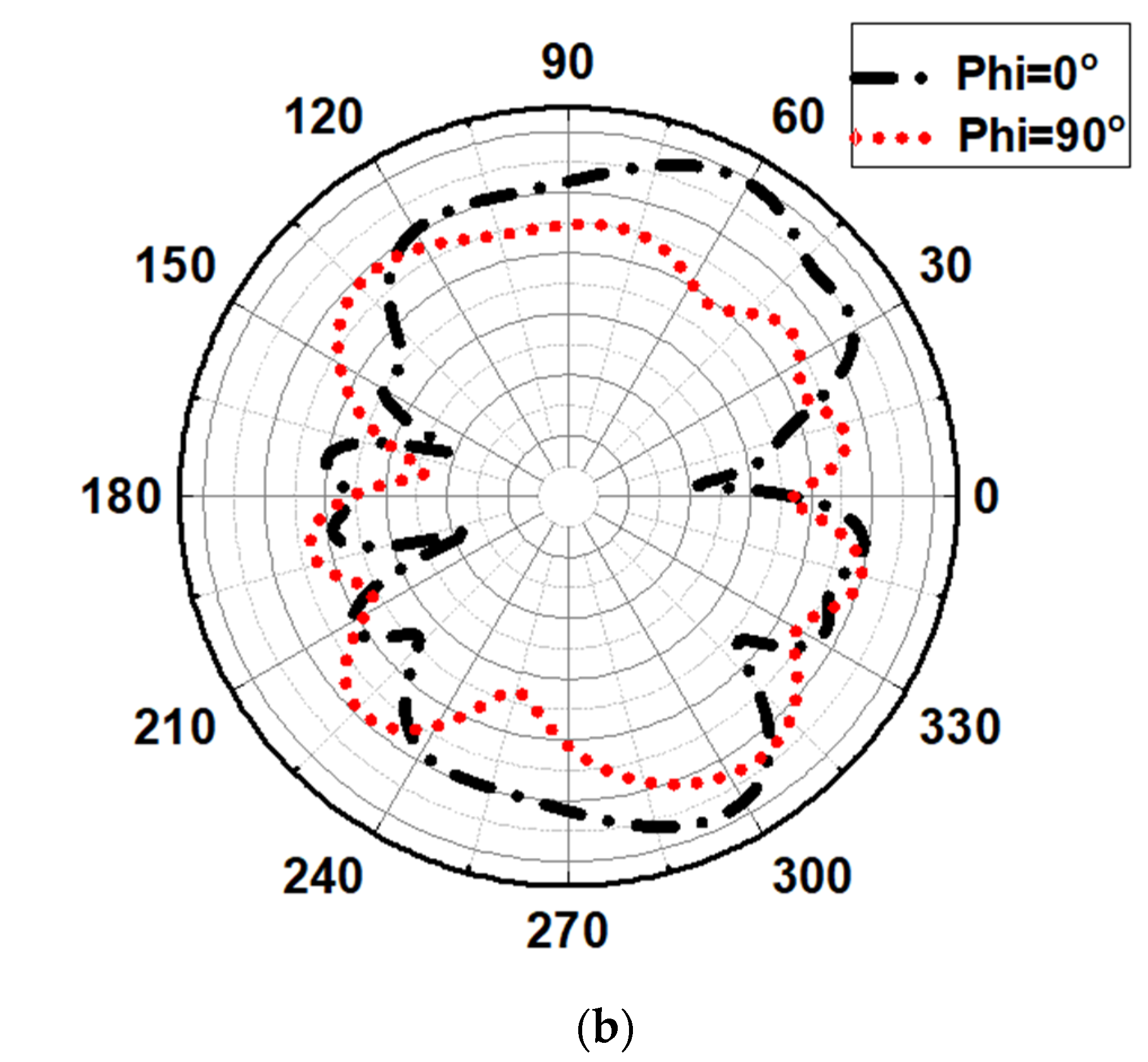
The radiation pattern for the proposed antenna for and is shown in Figure 17. It can be noted that the obtained pattern is directional and stable for both of the dual frequencies.
A comparison between the features of the proposed antenna with similar antennas is illustrated in Table 2. From the table, it can be found that the proposed structure has the advantage of compact size, multiband operation, directive radiation pattern, and a simple and planar structure over its counterparts.
5. Conclusions
A modified Franklin antenna array with a slotted ground structure to be utilized for mmW frequency is proposed. The nine patch antennas and folded dipole-like structures arranged in a three-by-three array manner are connected to a feeding network modified into a folded dipole like structure to provide good impedance matching to the overall antenna design. To achieve the optimum dimensions and suitable results, parametric analysis was carried out by modifying the antenna’s various parameters. The antenna offers dual-band resonance characteristics at 22.7 and 34.9 GHz with a total impedance bandwidth of about 2.8 and 2.1 GHz in simulation. For measurement, it shows dual-band operation at 22.8 and 35.3 GHz with impedance bandwidth of about 3 and 1.9 GHz, respectively, thus showing a good correlation between the simulated and measured results. The concept of the antenna array is deployed to enhance the gain of the antenna at a higher frequency of operation and nullify the side lobes. It also provides better impedance matching, as well as providing diversity reception. The antenna offers good gain, impedance matching, compact size, and stable radiation pattern, and thus acts as a very competitive candidate for 5G applications.
Author Contributions
All authors contributed equally for this work. All authors have read and agreed to the published version of the manuscript.
Funding
This research received no external funding.
Institutional Review Board Statement
Not applicable.
Informed Consent Statement
Not applicable.
Data Availability Statement
Not applicable.
Conflicts of Interest
The authors declare no conflict of interest.
References
- Goldsmith, A. Wireless Communications; Cambridge University Press: New York, NY, USA, 2005. [Google Scholar]
- Balanis, C.A. Antenna Theory: Analysis and Design; John Wiley & Sons: New York, NY, USA, 2016. [Google Scholar]
- Huang, K.-C.; Zhao, C. Millimetre Wave Communication Systems; Wiley: Hoboken, NJ, USA, 2011. [Google Scholar]
- Ali, T.; Aw, M.S.; Biradar, R.C. A Compact Bandwidth Enhanced Antenna Loaded with SRR For WLAN/WiMAX/Satellite Applications. Adv. Electromagn. 2018, 7, 78–84. [Google Scholar] [CrossRef]
- Ali, T.; Subhash, B.K.; Pathan, S.; Biradar, R.C. A compact decagonal-shaped UWB monopole planar antenna with truncated ground plane. Microw. Opt. Technol. Lett. 2018, 60, 2937–2944. [Google Scholar] [CrossRef]
- Ndip, I.; Le, T.H.; Schwanitz, O.; Lang, K.-D. A comparative analysis of 5G mmWave antenna arrays on different substrate technolgies. In Proceedings of the 2018 22nd International Microwave and Radar Conference (MIKON), Poznan, Poland, 14–17 May 2018; pp. 222–225. [Google Scholar]
- Jilani, S.F.; Alomainy, A. A multi-band millimeter-wave 2-D array based on enhanced Franklin antenna for 5G wireless systems. IEEE Antennas Wirel. Propag. Lett. 2017, 16, 2983–2986. [Google Scholar] [CrossRef]
- Pi, Z.; Khan, F. An introduction to millimeter-wave mobile broadband systems. IEEE Commun. Mag. 2011, 49, 101–107. [Google Scholar] [CrossRef]
- Solbach, K. Microstrip-Franklin Antenna. IRE Trans. Antennas Propag. 1982, 30, 773–775. [Google Scholar] [CrossRef]
- Alrifai, A.A. Improving the Frequency Range of Franklin’s Antenna. Int. J. Commun. Antenna Propag. (IRECAP) 2017, 7, 410. [Google Scholar] [CrossRef]
- Maharjan, J.; Kim, S.-W.; Choi, D.-Y. Franklin Array MIMO Antenna for 5G Applications. In Proceedings of the 2019 34th International Technical Conference on Circuits/Systems, Computers and Communications (ITC-CSCC), JeJu, Korea, 23–26 June 2019; pp. 1–4. [Google Scholar]
- Polivka, M.; Holub, A.; Mazanek, M. Collinear microstrip patch antenna. Radioengineering-prague 2005, 14, 40. [Google Scholar]
- Holub, A.; Polivka, M. Collinear microstrip patch antenna. In Passive Microwave Component and Antennas; InTech: Rijeka, Croatia, 2010; pp. 513–530. [Google Scholar]
- Kuo, C.H.; Lin, C.C.; Sun, J.S. Modified microstrip Franklin array antenna for automotive short-range radar application in blind spot information system. IEEE Antennas Wirel. Propag. Lett. 2017, 16, 1731–1734. [Google Scholar] [CrossRef]
- Chang, S.-H.; Liao, W.-J.; Peng, K.-W.; Hsieh, C.-Y. A Franklin Array Antenna for Wireless Charging Applications. PIERS Online 2010, 6, 340–344. [Google Scholar] [CrossRef] [Green Version]
- Wang, P.P.; Antoniades, M.A.; Eleftheriades, G.V. An Investigation of Printed Franklin Antennas at X-Band Using Artificial (Metamaterial) Phase-Shifting Lines. IEEE Trans. Antennas Propag. 2008, 56, 3118–3128. [Google Scholar] [CrossRef]
- Chaudhuri, S.; Kshetrimayum, R.S.; Sonkar, R.K. High Inter-port Isolation Dual Circularly Polarized Modified Franklin Microstrip Antenna. In Proceedings of the 2019 13th European Conference on Antennas and Propagation (EuCAP), Krakow, Poland, 31 March–5 April 2019; pp. 1–4. [Google Scholar]
- Jilani, S.F.; Alomainy, A. Millimeter-wave conformal antenna array for 5G wireless applications. In Proceedings of the 2017 IEEE International Symposium on Antennas and Propagation & USNC/URSI National Radio Science Meeting, San Diego, CA, USA, 9–14 July 2017; pp. 1439–1440. [Google Scholar]
- Boas, E.C.; Alves, A.A.C.; Ribeiro, J.A.J.; Cerqueira, S., Jr. A Novel Dielectric Slab Antenna Based on Microstrip-Franklin Excitation for mm-Waves. Journal of Microwaves. Optoelectron. Electromagn. Appl. 2020, 19, 203–213. [Google Scholar] [CrossRef]
- Vanaja, C.; Pavithra, N.; Sravya, N.; Manoj, M.; Dhanade, Y.B. Enhanced Franklin Antenna for the Future 5G Communication Applications. IJITEE 2019, 8, 1–5. [Google Scholar]
Figure 1.
Final antenna (a) top view and (b) bottom view.

Figure 2.
(a). Top view of the antenna (M) showing the patch array structure of the antenna, (b) bottom view of the antenna showing the full ground plane.
Figure 2.
(a). Top view of the antenna (M) showing the patch array structure of the antenna, (b) bottom view of the antenna showing the full ground plane.

Figure 3.
(a). Top view of the antenna (N) showing the patch array structure of the antenna, (b) bottom view of the antenna showing the ground plane with the first set of three cuts.
Figure 3.
(a). Top view of the antenna (N) showing the patch array structure of the antenna, (b) bottom view of the antenna showing the ground plane with the first set of three cuts.
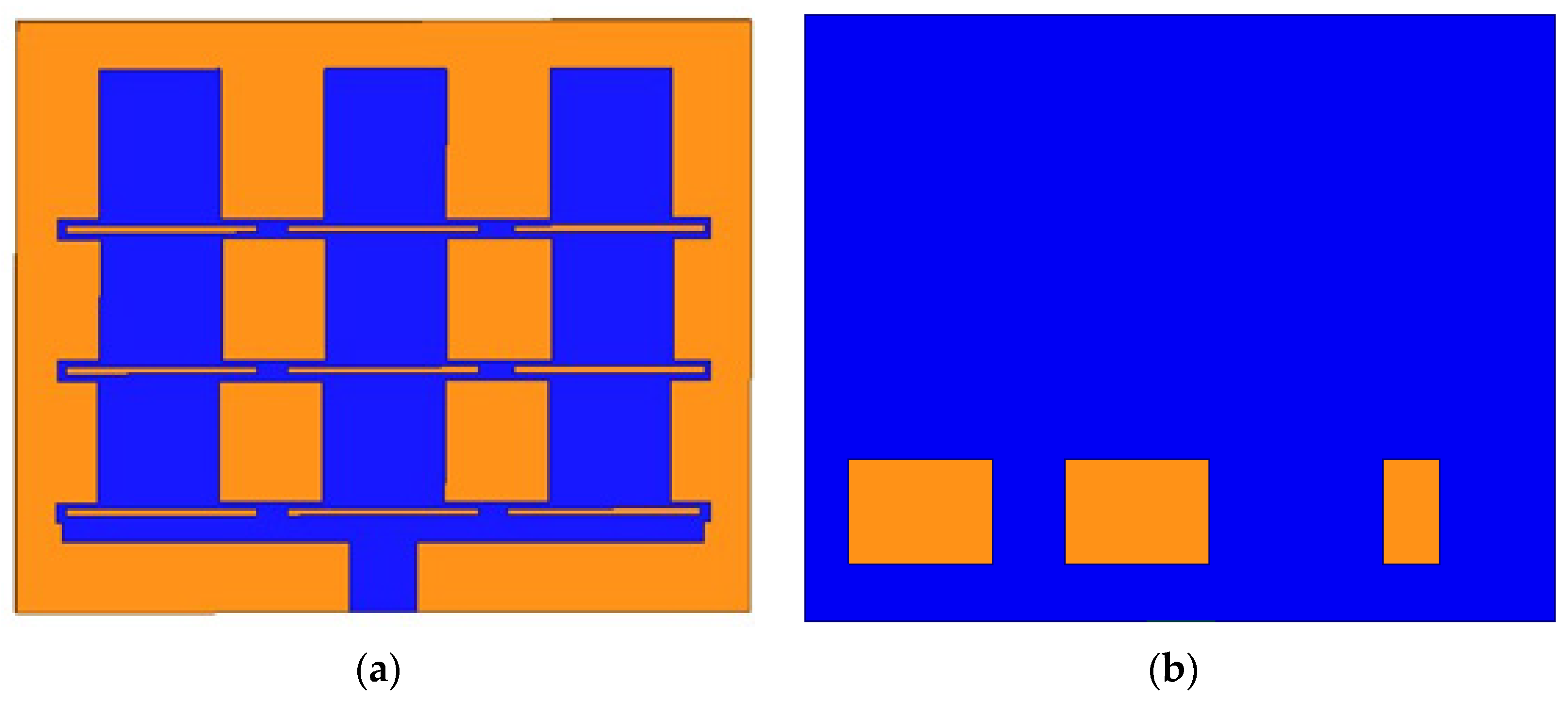
Figure 4.
(a) Top view of the antenna (O) showing the patch array structure of the antenna, (b) bottom view of the antenna showing the ground plane with the second set of three cuts.
Figure 4.
(a) Top view of the antenna (O) showing the patch array structure of the antenna, (b) bottom view of the antenna showing the ground plane with the second set of three cuts.

Figure 5.
(a). The top view of the antenna showing the antenna’s patch array structure, (b) the bottom view of the antenna showing the ground plane with the third set of three cuts.
Figure 5.
(a). The top view of the antenna showing the antenna’s patch array structure, (b) the bottom view of the antenna showing the ground plane with the third set of three cuts.
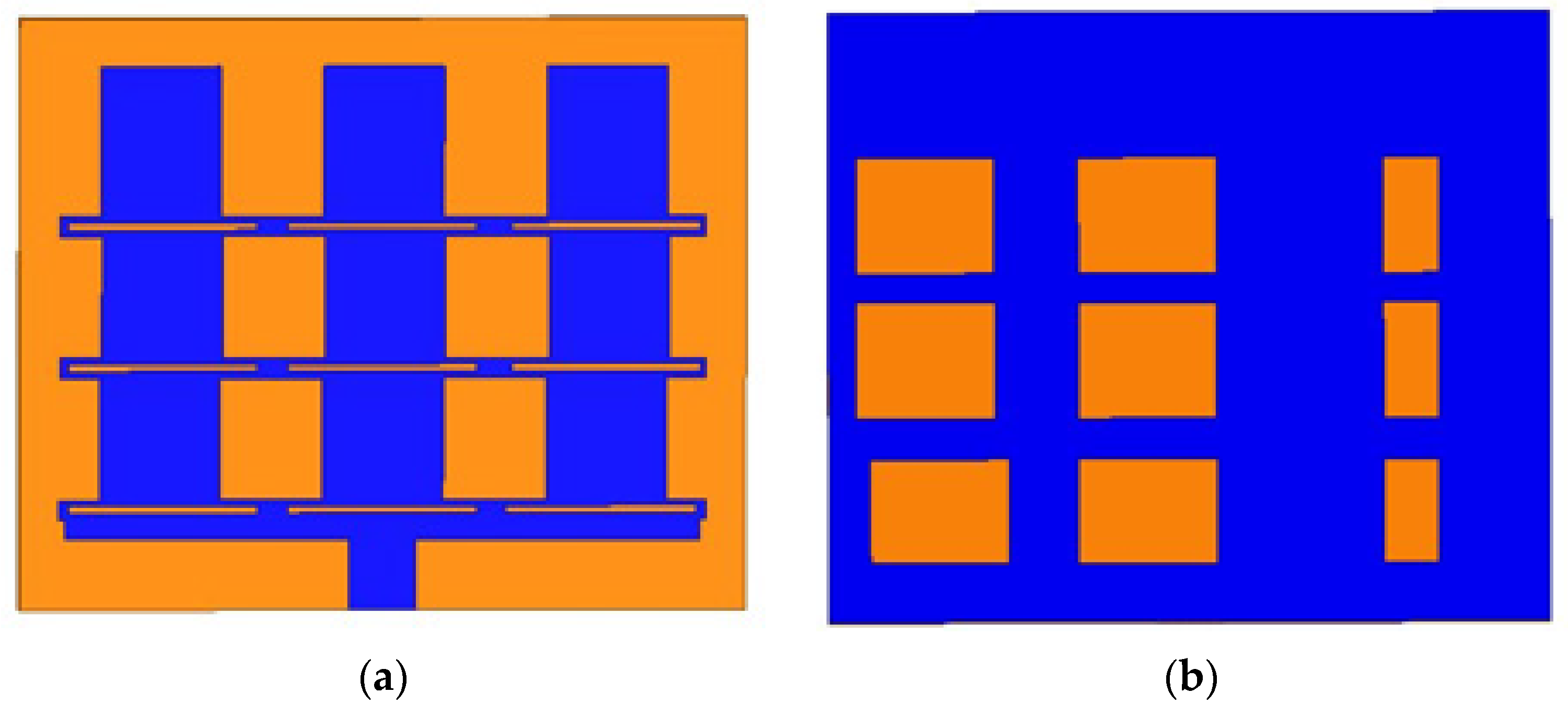
Figure 6.
Variation in reflection coefficient with frequency for different antenna configurations.

Figure 7.
Analysis of variation in the length of patch element PL.
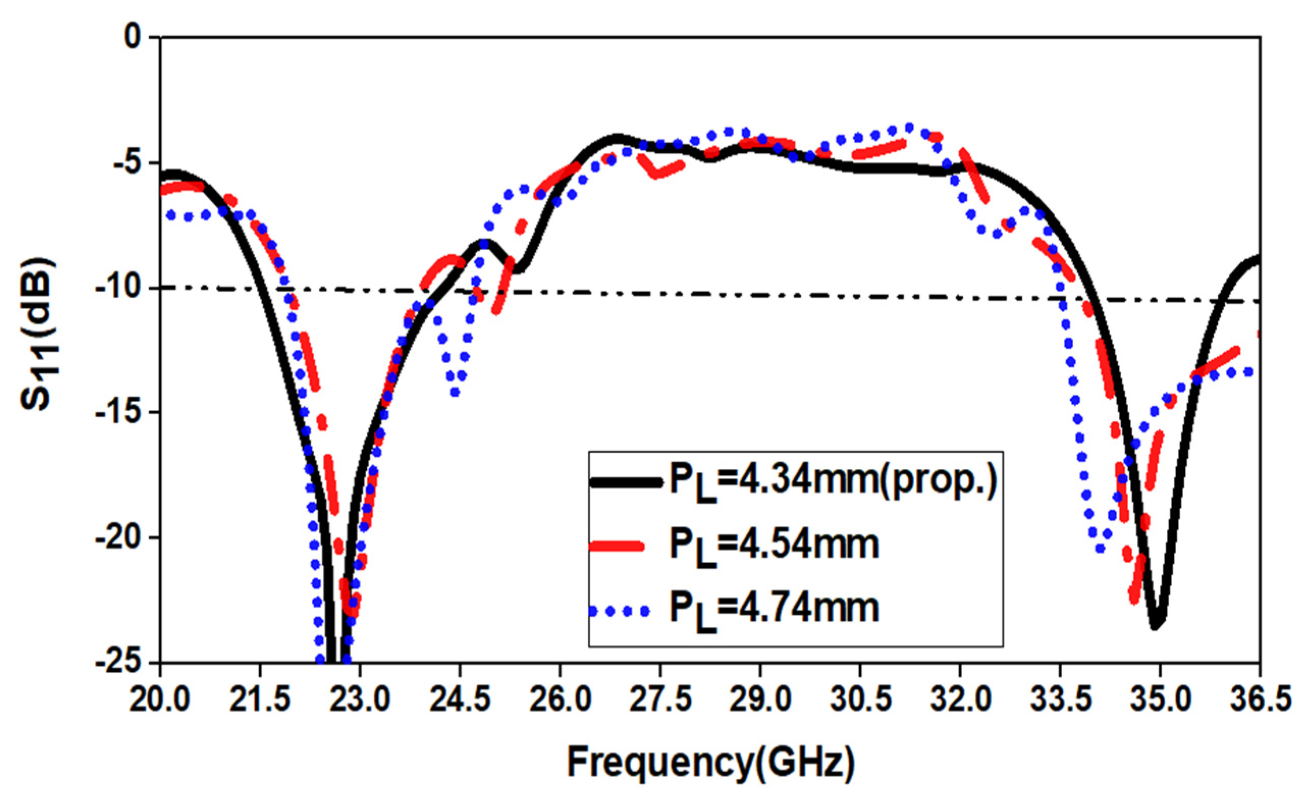
Figure 8.
Analysis of variation in the incremental length R.
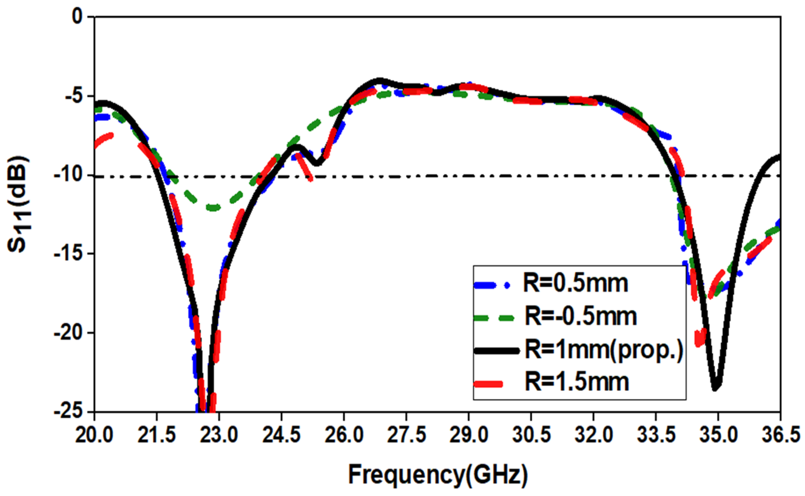
Figure 9.
Analysis of variation in the width of first type ground cut WG.
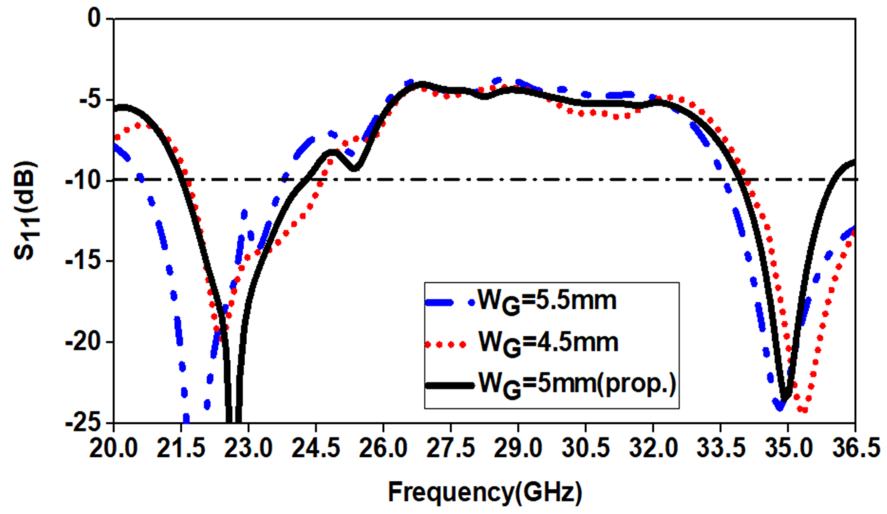
Figure 10.
Analysis of variation in the width of second type ground cut WC.
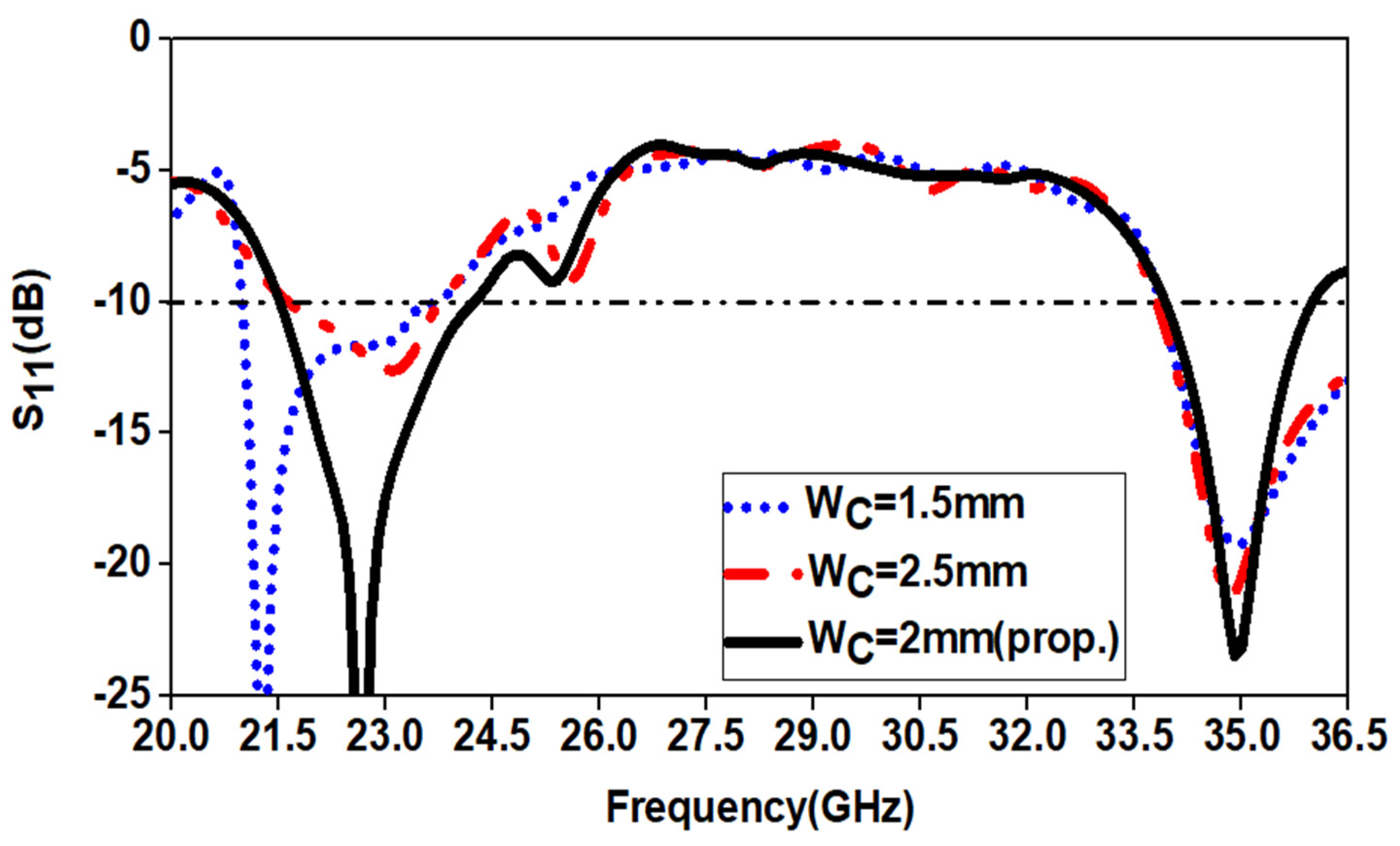
Figure 11.
Analysis of variation in the length of first type ground cut LG.
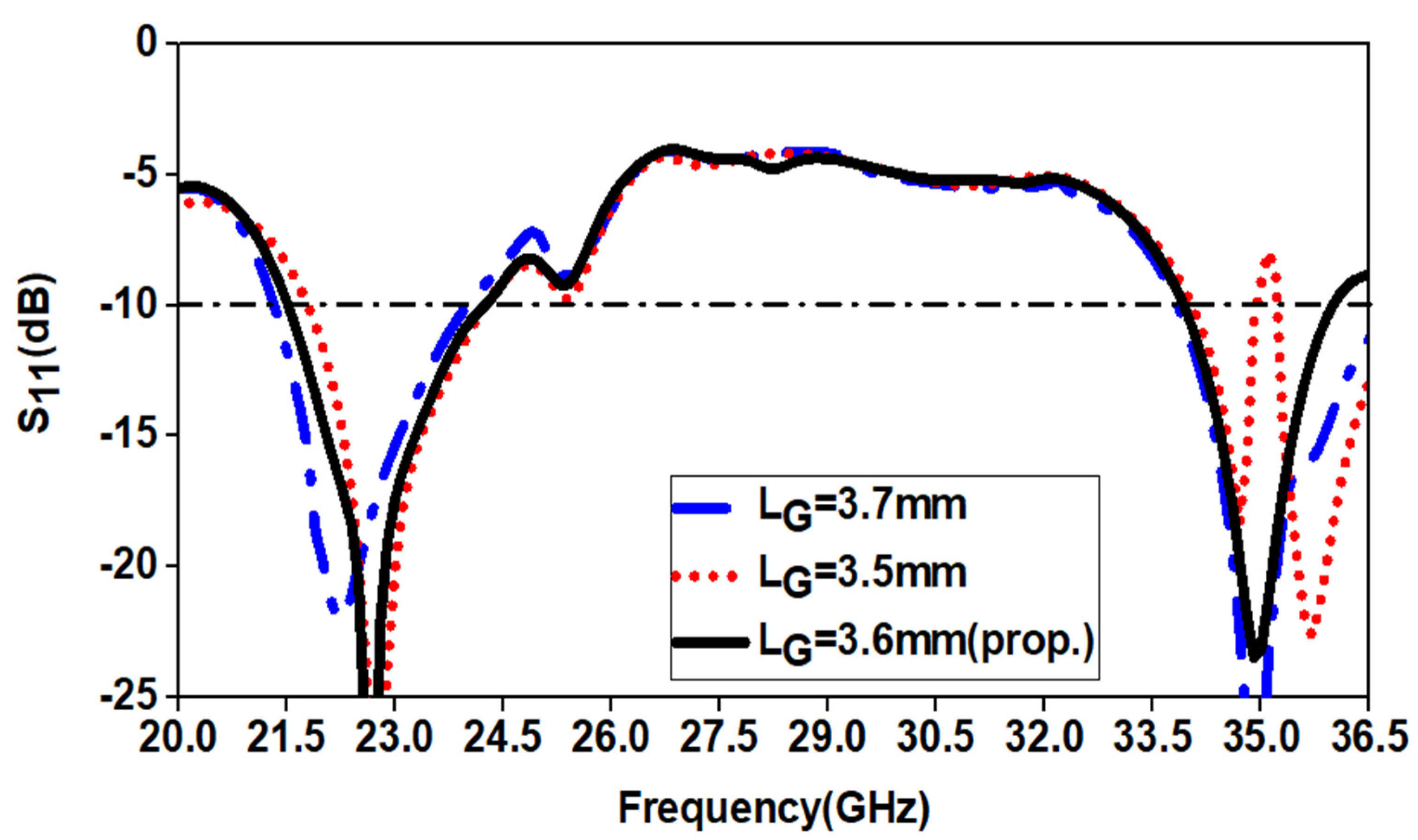
Figure 12.
Analysis of variation in the length of second type ground cut LC.

Figure 13.
Reflection coefficient vs. frequency of the proposed antenna.
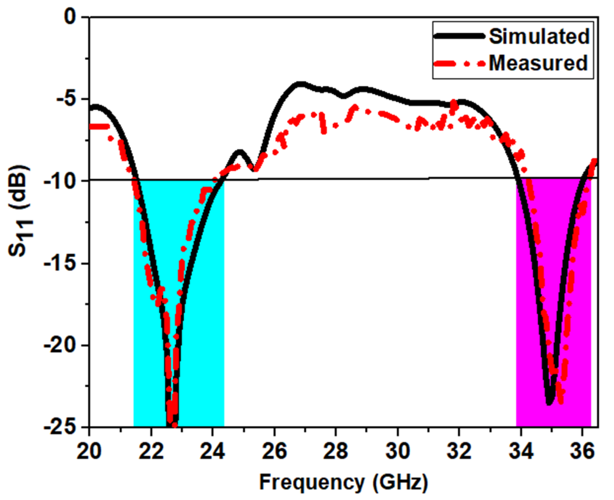
Figure 14.
Surface current distribution plots for frequencies (a) 22.7 and (b) 34.9 GHz.
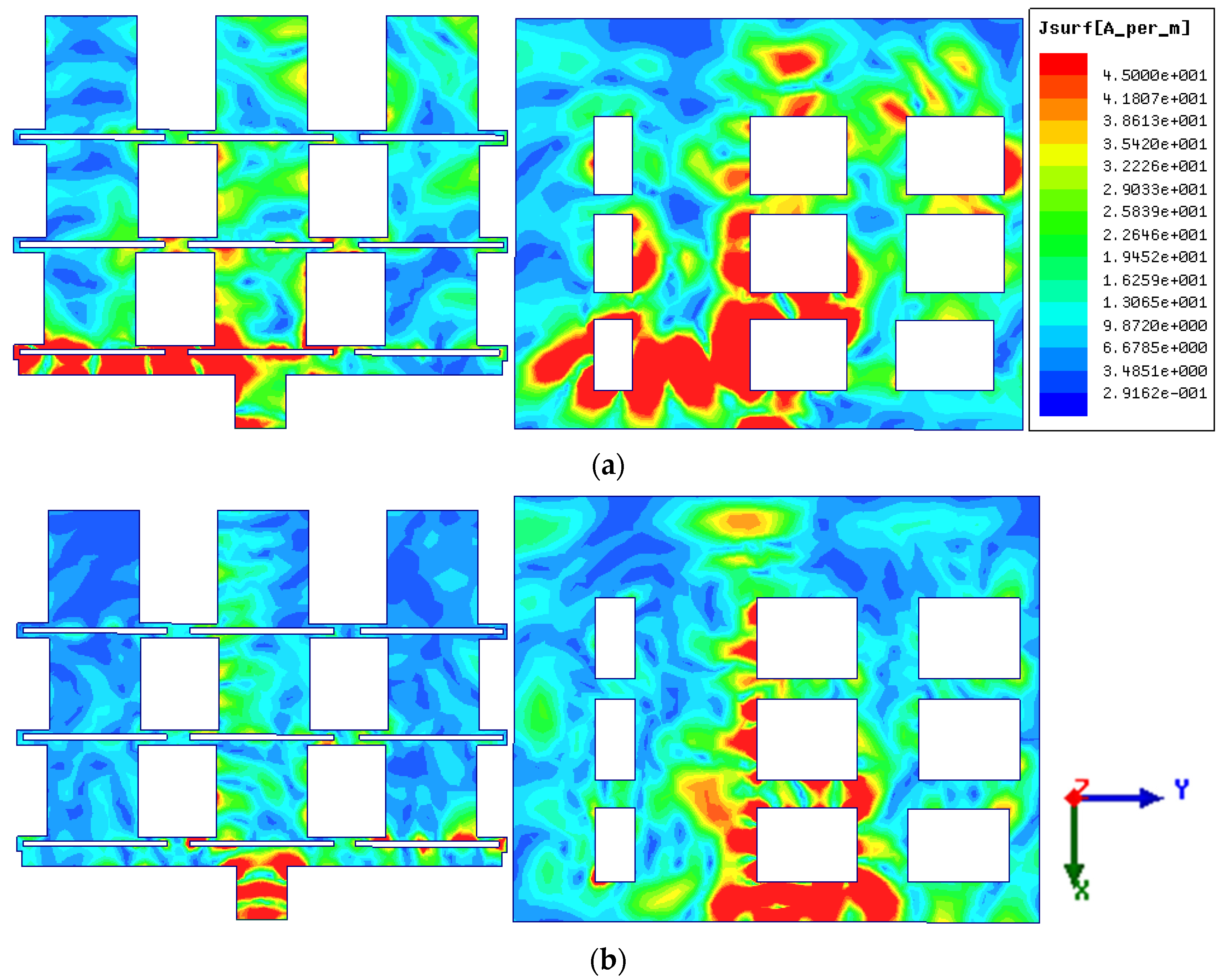
Figure 15.
Three-dimensional gain plot for frequencies (a) 22.7 GHz (b) 34.9 GHz.

Figure 16.
Variation of gain vs. frequency for the bandwidth of operation for a resonant frequency of (a) 22.7 and (b) 34.9 GHz, and variation of radiation efficiency vs. frequency for the bandwidth of operation for a resonant frequency of (c) 22.7 and (d) 34.9 GHz.
Figure 16.
Variation of gain vs. frequency for the bandwidth of operation for a resonant frequency of (a) 22.7 and (b) 34.9 GHz, and variation of radiation efficiency vs. frequency for the bandwidth of operation for a resonant frequency of (c) 22.7 and (d) 34.9 GHz.

Figure 17.
The radiation pattern for the proposed antenna at frequencies of (a) 22.7 and (b) 34.9 GHz.
Figure 17.
The radiation pattern for the proposed antenna at frequencies of (a) 22.7 and (b) 34.9 GHz.


Table 1.
Optimized dimensions of the final proposed antenna.
| Symbol | Parameters | (mm) |
|---|---|---|
| PL | Patch element length | 4.34 |
| PW | Patch element width | 4.3 |
| R | Patch element length extension for the first row | 1.0 |
| J | Spacing between the centers of patch elements in a row | 8.01 |
| FL | Folded dipole length | 1.4 |
| FW | Folded dipole width | 0.7 |
| SW | Matching stub width | 10.15 |
| SL | Matching stub length | 1.4 |
| fL | Feed length | 3.2 |
| fW | Feed width | 2.4 |
| Fg | The gap of the folded dipole | 0.26 |
| L | Length of substrate material | 21.0 |
| W | Width of substrate material | 26.0 |
| WG | Width of first type ground cut | 5.0 |
| WC | Width of second type ground cut | 2.0 |
| LG | Length of first type ground cut | 3.6 |
| LC | Length of second type ground cut | 4.0 |
Table 2.
Comparison of various antenna performance indicators.
| Ref. | Antenna Type | No of Elements | Resonating Frequency (GHz) | Bandwidth (%) | Gain (dBi) | Size (mm2) | Advantage |
|---|---|---|---|---|---|---|---|
| [12] | Collinear Microstrip Patch Antenna | 3 | 0.869 | 2.80 | 12.4 | It has a directional pattern. | |
| [13] | Collinear Microstrip Patch Antenna | 3 | 2.4 | 7.10 | 15.8 | Simple structure without the need for any feeding network. | |
| [14] | Modified Microstrip Franklin Array Antenna | 1, 3, and 5 | 24 | 1.04 | 6, 8, and 11 | High absolute gain, good directivity, and large-range coverage. | |
| [15] | Franklin Array Antenna | 32 | 2.4 | 8.33 | 12 | High gain, enlarged antenna aperture, increase in available power. | |
| [17] | Circularly Polarized Franklin Microstrip Antenna | 12 | 6.9 | 5.76 | 3.1 | More than 64% of the −10 dB impedance bandwidth is usable in CP mode, low axial ratio, high inter-port isolation, and squinted beams. | |
| [18] | Conformal Antenna array | 6 | 29 | 19.78 | 8.3 | Compact, flexible, and wideband antenna array | |
| [19] | Dielectric Slab Antenna based on microstrip-Franklin Excitation | 1 | 30 | 7.6 | 6.6 | Simple planar geometry. | |
| [20] | Enhanced Franklin antenna with defected ground structure | 9 | 25.2 | 22.22 | 10.1 | Directive radiation pattern and cost effective | |
| Proposed Antenna | 9 | 22.7 and 34.9 | 12.2 and 6 | 7.8 and 9.73 | Compact size, multiband operation, directive radiation pattern, simple and planar structure. |
Publisher’s Note: MDPI stays neutral with regard to jurisdictional claims in published maps and institutional affiliations. |
© 2021 by the authors. Licensee MDPI, Basel, Switzerland. This article is an open access article distributed under the terms and conditions of the Creative Commons Attribution (CC BY) license (http://creativecommons.org/licenses/by/4.0/).
Share and Cite
MDPI and ACS Style
Surendran, A.; B, A.; Ali, T.; Kumar, O.P.; Kumar, P.; Anguera, J. A Dual-Band Modified Franklin mm-Wave Antenna for 5G Wireless Applications. Appl. Sci. 2021, 11, 693. https://doi.org/10.3390/app11020693
AMA Style
Surendran A, B A, Ali T, Kumar OP, Kumar P, Anguera J. A Dual-Band Modified Franklin mm-Wave Antenna for 5G Wireless Applications. Applied Sciences. 2021; 11(2):693. https://doi.org/10.3390/app11020693
Chicago/Turabian StyleSurendran, Arjun, Aravind B, Tanweer Ali, Om Prakash Kumar, Pradeep Kumar, and Jaume Anguera. 2021. "A Dual-Band Modified Franklin mm-Wave Antenna for 5G Wireless Applications" Applied Sciences 11, no. 2: 693. https://doi.org/10.3390/app11020693
Note that from the first issue of 2016, this journal uses article numbers instead of page numbers. See further details here.