
A Dual-Mass Resonant MEMS Gyroscope Design with Electrostatic Tuning for Frequency Mismatch Compensation


1
Department of Mechanical and Aerospace Engineering, Politecnico di Torino, Corso duca degli Abruzzi 24, 10129 Torino, Italy
2
Department of Mechatronics Engineering, National University of Sciences and Technology, Islamabad 44000, Pakistan
3
National Centre of Robotics and Automation (NCRA), Islamabad 44000, Pakistan
*
Author to whom correspondence should be addressed.
Appl. Sci. 2021, 11(3), 1129; https://doi.org/10.3390/app11031129
Submission received: 5 January 2021
/
Revised: 19 January 2021
/
Accepted: 22 January 2021
/
Published: 26 January 2021
(This article belongs to the Special Issue Novel Technology and Applications of Micro/Nano Devices and System)
Abstract
:The micro-electro-mechanical systems (MEMS)-based sensor technologies are considered to be the enabling factor for the future development of smart sensing applications, mainly due to their small size, low power consumption and relatively low cost. This paper presents a new structurally and thermally stable design of a resonant mode-matched electrostatic -axis MEMS gyroscope considering the foundry constraints of relatively low cost and commercially available silicon-on-insulator multi-user MEMS processes (SOIMUMPs) microfabrication process. The novelty of the proposed MEMS gyroscope design lies in the implementation of two separate masses for the drive and sense axis using a unique mechanical spring configuration that allows minimizing the cross-axis coupling between the drive and sense modes. For frequency mismatch compensation between the drive and sense modes due to foundry process uncertainties and gyroscope operating temperature variations, a comb-drive-based electrostatic tuning is implemented in the proposed design. The performance of the MEMS gyroscope design is verified through a detailed coupled-field electric-structural-thermal finite element method (FEM)-based analysis.
1. Introduction
With the constant evolution of micromachining technology, the vibratory micro-electro-mechanical systems (MEMS) gyroscopes have emerged as an innovative solution for the measurement of angular velocity in inertial sensing applications due to their light weight, small size, less power consumption and ease of integration with electronics. The operation of a -axis MEMS gyroscope involves oscillation of a proof mass in a given axis and generation of Coriolis force orthogonal to the axis of oscillation and angular rotation. These Coriolis vibratory-rate MEMS gyroscopes have shown significant potential in the past decade for fulfilling the needs of many applications such as guidance systems, industrial robotics, tactical-grade navigation systems and in the automotive industry [1,2,3]. The performance of vibratory MEMS gyroscopes is, however, still behind the conventional bulky gyroscopes due to their mechanical instability, microfabrication process uncertainties and robustness against the operating environmental variations. Thus, improvement of the mechanical design of MEMS gyroscopes to achieve better performance is an area of interest for MEMS designers [4,5].
The MEMS gyroscopes are generally designed to operate in resonance with the match of drive- and sense-mode resonant frequency values. This allows achieving high mechanical sensitivity and minimizing the long-term drift in performance, i.e., bias instability [6]. However, matching the drive- and sense-mode resonant frequency in a MEMS gyroscope becomes challenging in the presence of microfabrication process tolerances and high-temperature operating conditions. To minimize the effect of external factors on the performance of MEMS gyroscopes, complex multi-degree of freedom (multi-DoF) mechanical structures, based on nonresonant operation, have been reported in the literature [7,8,9]. In addition to the structural complexity, the issue of low mechanical sensitivity is inherent to nonresonant MEMS gyroscope designs. Another method of reducing the frequency difference between the drive- and sense-mode resonant frequency values in MEMS gyroscopes is to implement the additional feedback control electronics for the error compensation, which leads to the addition of electrical noise and operational complexity [10,11,12].
As discussed earlier, resonant MEMS gyroscopes usually operate in a closed loop in order to maintain the performance characteristics over a wide range of environmental conditions. There are multiple errors that have to be mitigated in order to obtain optimal performance, and for this reason some design choices have to be made that can help reduce the errors and avoid overly complex feedback electronics. A major error source is the mismatch in the frequencies of drive and sense modes. This can cause the performance of the gyroscope to reduce drastically since even a slight mismatch can reduce the amplitude response of a mode matched gyroscope significantly. To mitigate this error, frequency tuning is required, and for this purpose a phenomenon called electrostatic spring softening is used to change the stiffness of the structure electronically and therefore change the frequency. This method allows the designer to reduce the mismatch and to get the optimal performance of the MEMS gyroscope [13,14]. The number of proof masses in resonant MEMS gyroscopes can affect the common mode errors and therefore the performance of the gyroscope. The designs utilizing multiple proof masses operate in the antiphase mode, which assures minimization of the net reaction forces and moments on the anchors and thus mitigates the energy loss through the substrate [15]. This design approach results in a larger overall size but better performance. Another approach is to use a single proof mass, which leads to a smaller device footprint but with worse performance. Consequently, tradeoffs have to be made between better performance and keeping the size of the device to a minimum [16,17,18].
In this paper, a new mechanically stable design of an electrostatically actuated -axis resonant MEMS gyroscope is presented that utilizes two separate masses for the drive and sense axis. The two separate-masses-based configuration allows minimizing the cross-axis coupling and achieves high thermal stability. The proposed MEMS gyroscope sensor is designed to be used in industrial automation based IoTs and has the main advantage of improving the reliability of the measurement with respect to environmental and constructive imperfections. Moreover, the design is developed and optimized considering the microfabrication process limitations of the commercially available low-cost silicon-on-insulator multi-user MEMS processes (SOIMUMPs) microfabrication process. The working of the proposed design is verified through coupled field electro-mechanical-thermal finite element method (FEM) simulations with the demonstration of the electrostatic tuning effectiveness for the mode-matching between the drive and sense modes of the MEMS gyroscope.
2. Mechanical Design and Working Principle
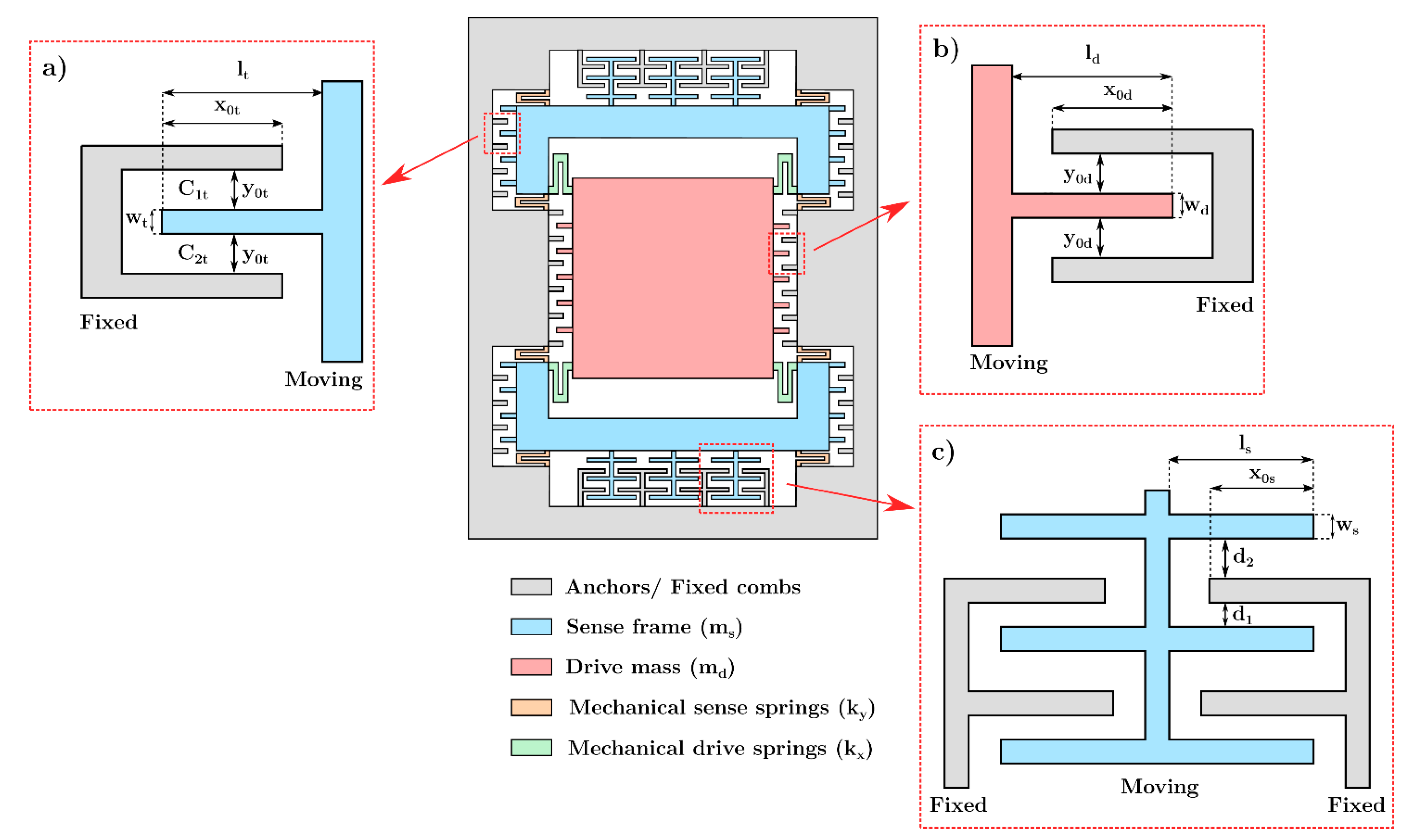
Figure 1 shows the schematic diagram of the proposed dual-mass MEMS gyroscope design. The design consists of two separate masses for the drive and sense axis, which are fully decoupled. The drive mass is nested inside the sense frame through four folded beams (), which allow motion of the mass in the drive axis but limit its displacement in the sense axis. Another set of eight folded spring beams () connects the sense frame to the anchors and allows its displacement in the sense direction only. An oscillatory motion along the drive direction (-axis) is achieved through a set of interdigitated combs-based electrostatic actuators attached to the drive mass .
When the gyroscope is subjected to an external angular velocity in the -axis, a Coriolis force is developed that leads to consequent displacement of the sense mass in the sense direction (-axis), which is orthogonal to both the drive direction and angular rotation axis. The mechanical suspension beams attached to the drive mass do not allow its oscillation in the -axis. However, since the drive mass is nested inside the sense frame, both the drive and sense frame move in the -axis as a result of developed Coriolis force. The displacement of the sense mass is measured by using sensing parallel plates, which act as a capacitive transducer. The parallel sensing plates are designed in a gap–antigap-based differential layout and are attached to the sense frame such that their relative motion along the drive direction is restricted, thus minimizing the cross-axis coupling in the proposed MEMS gyroscope design. Finally, to control the resonant frequency difference between the two modes, due to foundry process tolerances or thermal variations, electrostatic tuning combs based on the electrical spring softening concept are attached to the sense frame. Table 1 shows the design parameters and their corresponding values for the proposed MEMS gyroscope. One of the main design constraints attributed to the SOIMUMPs microfabrication process is that the mechanical anchors or fixed parts of the MEMS device must be designed at the periphery since this process does not allow anchor regions in the center owing to the limitations of the etching step of the microfabrication process [19]. Accordingly, all the fixed parts are moved on the periphery. In addition to respecting the limits imposed by the microfabrication process, the design process has required ensuring the matching of the drive- and sense-mode resonant frequency values. Moreover, it is necessary to consider that electrostatic tuning will be implemented to compensate for the frequency mismatch. This means that the sense frequency value must be slightly greater than the drive one.
3. Mathematical Model of the Proposed MEMS Gyroscope
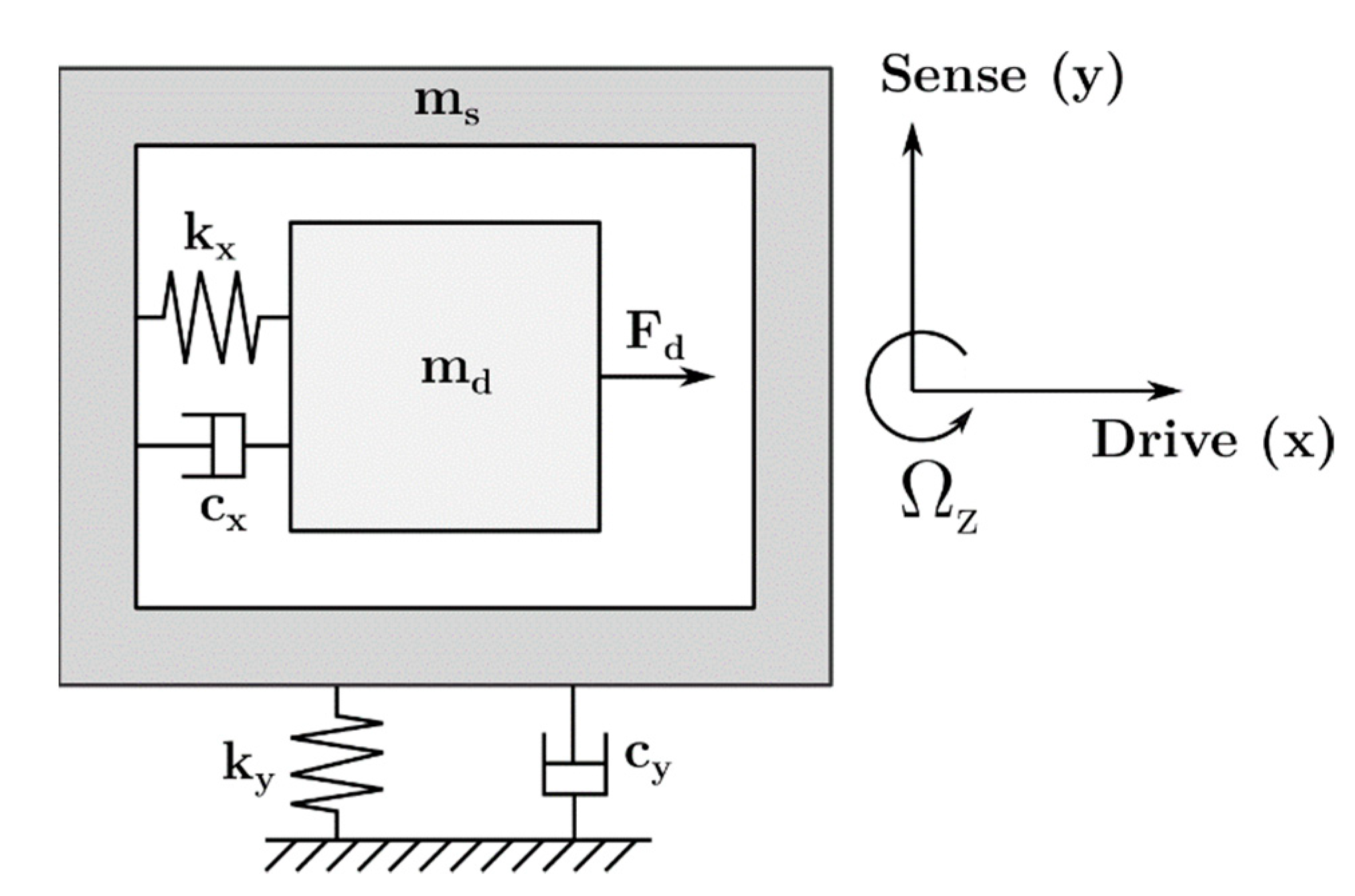
The lumped-parameter model of the MEMS gyroscope design is shown in Figure 2. The drive mass is nested inside the sense frame through the mechanical spring and is free to oscillate along the drive direction, while the sense frame is anchored to the substrate by means of the mechanical spring and is constrained to oscillate only in the sense direction. The air viscous damping between the comb-drive-based actuators attached to the drive mass , tuning combs and sensing parallel plates attached to sense frame are represented by and , respectively. When an angular velocity is applied along the -axis, the equations of motion for the MEMS gyroscope design can be written as:
where is the electrostatic actuation force applied to the mass and is the Coriolis force acting on the one degree-of-freedom oscillator in the sense direction.
3.1. Stiffness Calculation for the Mechanical Beams
Mechanical spring beams in the design are modeled as fixed-guided beams that are connected in parallel. The overall stiffness in the drive axis is due to four folded microbeams that are compliant in the -axis and connect the drive mass to the sense frame. The drive direction stiffness can be calculated as:
where is the Young’s modulus, is the thickness of the microbeams, and and are the width and length of the folded microbeams, respectively. In the sense direction, the mechanical suspension consists of eight folded microbeams that connect the sense mass to the anchors. The sense direction mechanical stiffness can be calculated as:
where and are the width and length of the folded microbeams, respectively, in the sense axis.
3.2. Electrostatic Tuning for Mode-Matching
The configuration scheme of electrostatic tuning combs implemented in the MEMS gyroscope design to achieve the resonant frequency match between the drive and sense axis is shown in Figure 1. The interdigitated combs are varying-gap structures with an equal air gap and attached to both sides of the sense frame. Since the movable combs can move only in the sense direction, the comb-drive-based tuning structures only affect the sense-mode dynamics. Considering a single tuning-comb structure, the sense frame displacement in the positive -direction leads to an increase in the upper capacitance and a decrease in the bottom capacitance created between fixed and moving comb fingers. This capacitance variation can be expressed as:
where is the free space permittivity, is the overlap area and is the nominal gap between the fingers. When a DC tuning tension is given to the anchored comb, the moving comb finger is subjected to two electrostatic forces, namely and and expressed as nonlinear functions of the -displacement:
Considering moving fingers, the comb-drive-based electrostatic tuning structures can be modeled as a series of capacitors. Accordingly, the total electrostatic tuning force can be obtained as:
The electrostatic spring constant due to the force nonlinearity can be calculated by taking the derivative of the total electrostatic force with respect to the -axis displacement:
Considering , Equation (8) can be simplified as follows:
The electrostatic tuning force acts only in the -direction and does not cause a shift in the drive resonant frequency , while the sense resonant frequency always decreases with increasing DC tension across the tuning electrodes, according to the following expression:
According to Equation (10), the sense resonant frequency can be tuned by adjusting the tuning voltage applied to tuning electrodes in order to achieve the mode-matching condition, i.e., = at a certain voltage.
3.3. Air Damping Model for MEMS Gyroscope
In resonant MEMS gyroscopes, the accurate estimation of the viscous air damping is crucial since it affects the overall quality factor and hence sensitivity. In the proposed gyroscope design, both the slide and squeeze film air-damping factors result in the energy dissipation.
In the drive axis, the slide film air damping is the sole energy-loss mechanism since the comb-drive fingers slide parallel to each other with an application of actuation voltage in the -direction. The movement of the sense frame and drive mass in the y-axis results in the squeeze film air damping [20]. With the displacement of the sense mass in the y-axis, the air between the oscillating and stationary parallel plates is compressed. The same damping effect occurs in the interdigitated drive and tuning comb fingers. The damping coefficients in the x-axis and y-axis, for the gyroscope design, due to slide and squeeze film damping can be obtained as:
where , , , is the effective viscosity of air, , and are respectively the total number of comb-drive fingers attached to the drive mass, electrostatic tuning-comb fingers and sensing parallel plates both attached to the sense frame, , and are the corresponding overlap lengths, and are the gap between the comb-drive fingers and tuning-comb fingers, respectively, while and are the smaller and larger gap sizes of the sensing parallel plates, respectively. The effective air viscosity at given temperature and pressure in the case of slide film damping can be expressed as [21]:
while the effective air viscosity in squeeze film damping is given as [22]:
where is the Knudsen number and is the air viscosity at room conditions. The Knudsen number is an estimate of the gas rarefaction effect and it can be defined as;
where λ is the mean free air path at a fixed temperature and is the air gap thickness in the drive combs, tuning combs and sensing parallel plates, respectively equal to , and . The λ value can be estimated as [23]:
where is the mass of air, and are the air pressure and temperature, respectively, and is the Boltzmann constant.
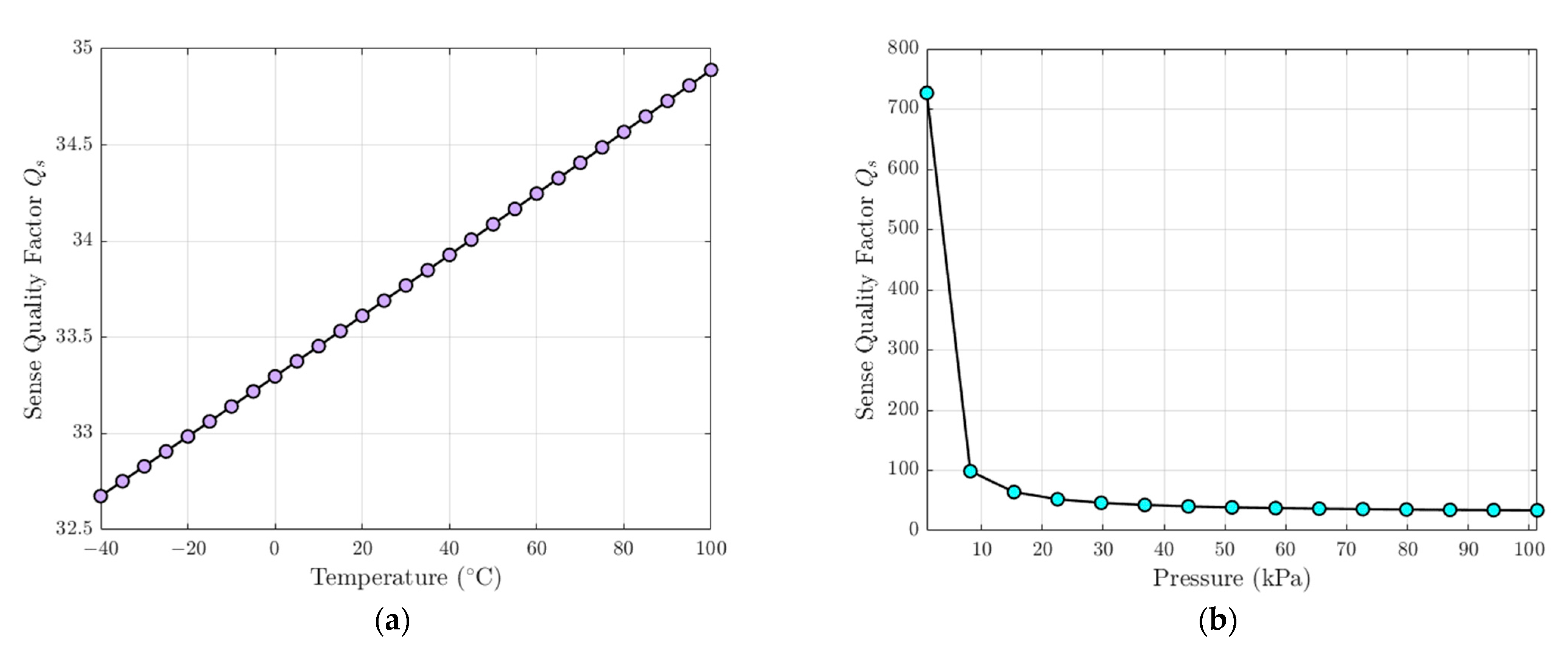
Figure 3 shows the effect of temperature and pressure variations on the sense Quality Factor value for the proposed MEMS gyroscope, equal to . The variation of the sense Quality Factor can be considered as negligible when the ambient pressure is fixed at 101 kPa and the operating temperature increases in the range of −40 °C to 100 °C (Figure 3a), while for a fixed temperature at 25 °C the sense Quality Factor drastically decreases as the operating pressure increases (Figure 3b).
4. Multiphysics FEM Model of the Proposed MEMS Gyroscope
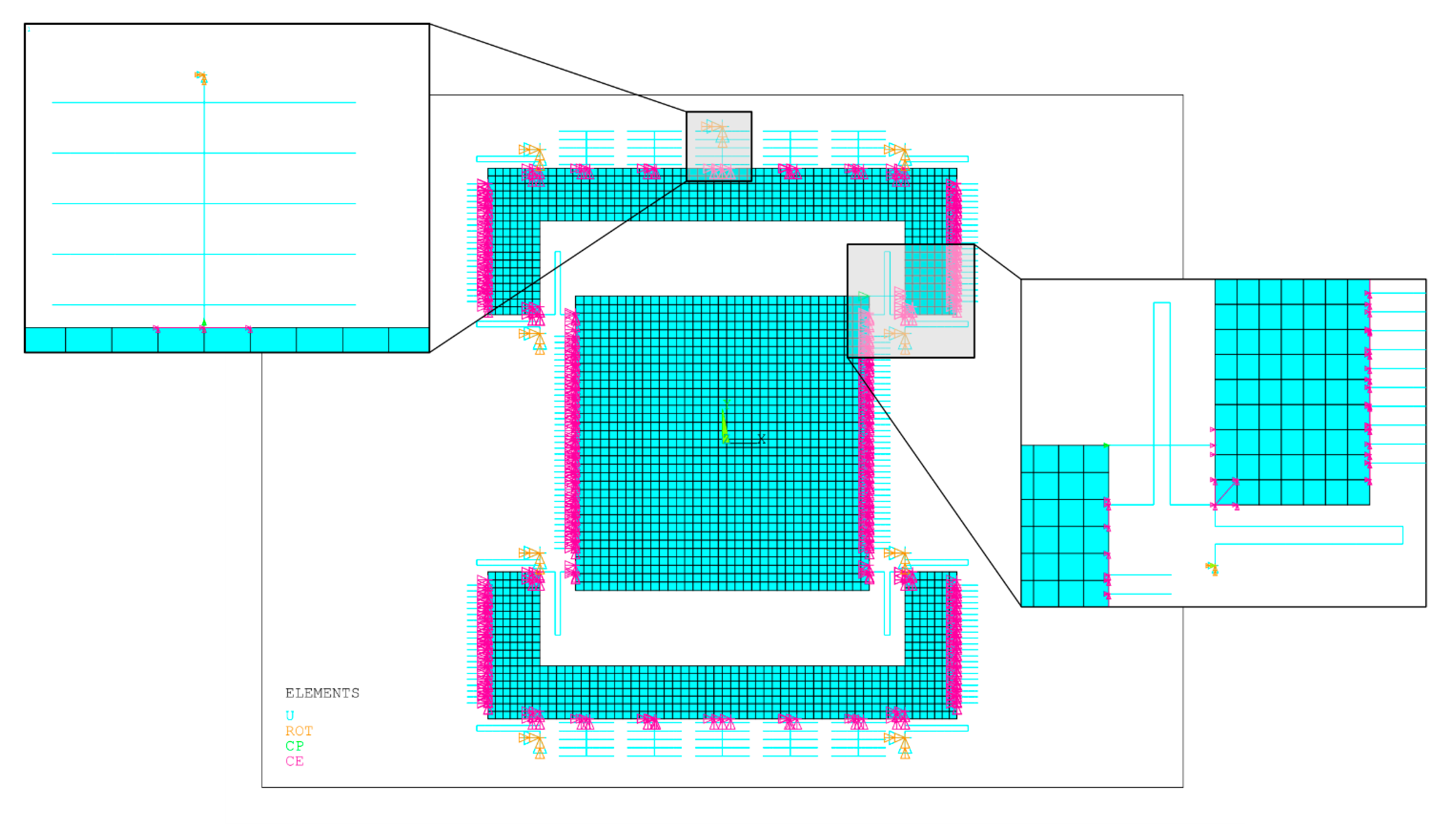
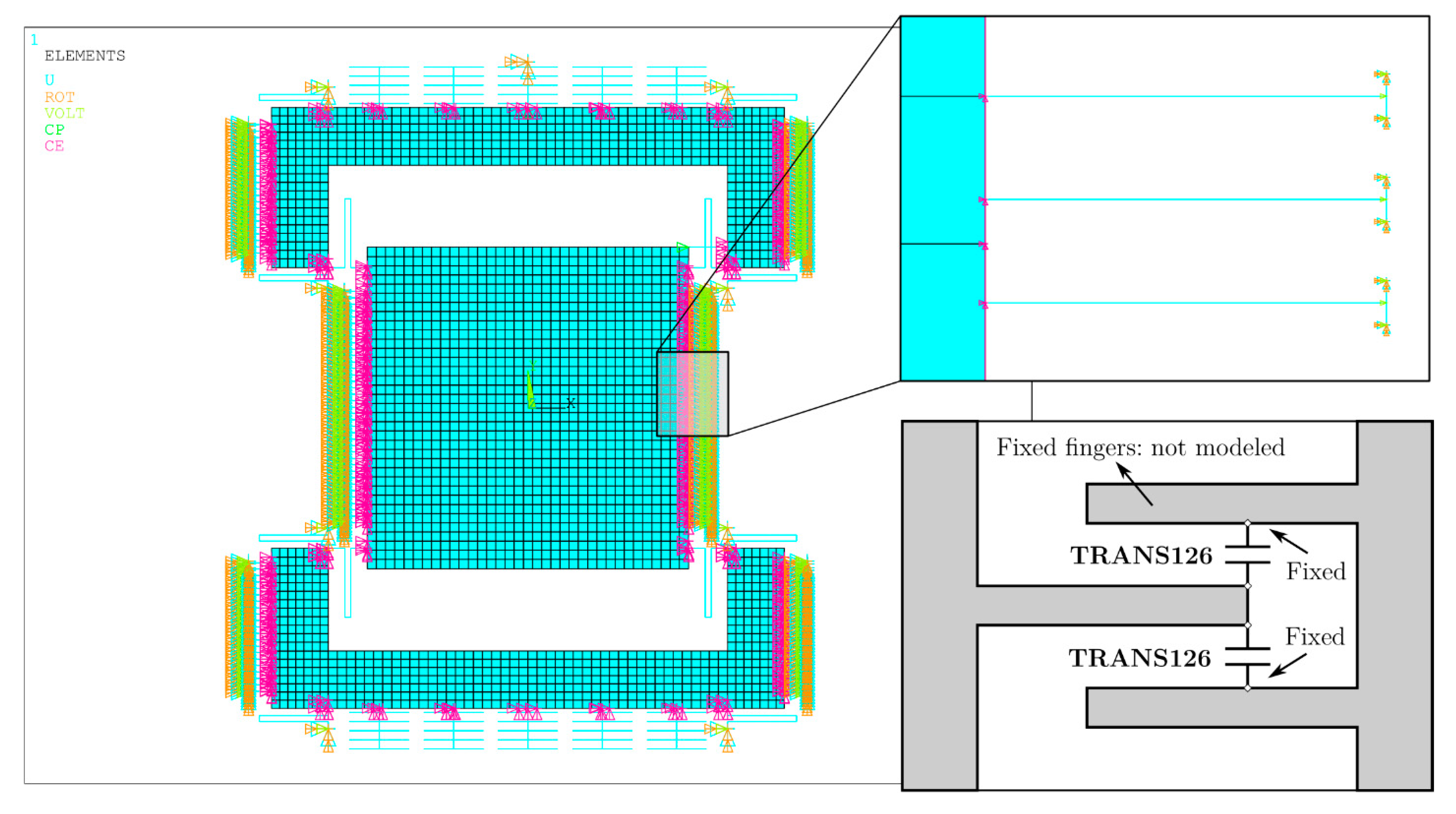
The performance of the proposed MEMS gyroscope design is verified through FEM based simulations in ANSYSTM. Figure 4 shows the meshed model of the MEMS gyroscope design. The adopted mesh has been designed to optimize as much as possible the required computational resources. The structure is meshed using 2D SHELL181 elements for the drive mass and sense frame, while BEAM188 elements are adopted to model the suspension systems, the comb-drive fingers, the tuning-comb fingers and the sense parallel plates. Since the rotational stiffness around the -axis (ROTZ stiffness) of SHELL181 elements is an artificial value, it is inconsistent to connect only one node of a BEAM188 element to a SHELL181 element such that a rotational degree of freedom (DOF) of the beam element corresponds to the rotational around the z-axis (ROTZ) of the shell element. Accordingly, constraints equations are used to couple the rotational degree of freedom around the -axis (ROTZ-DOF) of the single nodes shared by the BEAM188 and SHELL181 elements with the in-plane translations DOFs, namely UX and UY, of adjacent shell element nodes. Fixed supports are added at the end of sense spring beams connected to the external anchors.
Air viscous damping effects in the drive and sense direction are included in the FEM model based on the analytical estimation of damping coefficients and . These coefficients are specified directly as input and the corresponding values as real constants of the special element type having viscous damping characteristics, i.e., COMBIN14 element. Relying on the lumped mass-spring damper model representation shown in Figure 2, at least two COMBIN14 elements should be used: an element oriented according to the -axis and connecting the drive mass and sense frame is used for model damping in the drive direction, while sense damping is represented by an element oriented according to the -axis and connecting the sense frame with the external anchors. In order to obtain a reliable modeling of damping effects, COMBIN14 and SHELL181 elements are bound together by coupling the corresponding DOFs of the two contact nodes using CP command in ANSYSTM.
The comb drives and tuning combs are modeled as a series of capacitors, as each couple of moving fingers forms a pair of parallel plates. The one-dimensional transducer (1-D) TRANS126 elements are used to model the capacitance of comb-drive-based actuators and tuning-comb fingers [24]. As shown in Figure 5, two elements are connected at the end of each moving finger, while the mechanical degrees of freedom of nodes connected to the stationary fingers are fixed. An electromechanical coupling is thus achieved between the distributed mechanical and lumped electrical domains. The TRANS126 element has two DOFs at each node, i.e., the translation in the nodal , or -direction and an electric potential. This allows modeling the capacitive response of a mechanical microstructure to a movement in a fixed direction. Since the fringing field along the lateral edges of the comb drive and tuning-comb fingers is neglected, indefinite capacitor theory is adopted. The capacity characteristics of the elements connected to the comb-drive fingers is a function of the -displacement and it is set as a real constant, by imposing the coefficients obtained using the following equation:
where the sign + or − respectively depends on whether the capacity increases or decreases according to the displacement in the -direction. Similarly, the capacity characteristics of the elements attached to the tuning-comb fingers is a nonlinear function of the gap distance between their corresponding nodes, which depends on the -displacement and is also set as real constant, by using the value of the coefficient obtained with the following equation:
The actuation and tuning voltage are applied to the nodes connected to the fixed actuation and tuning combs, respectively, and the electrostatic potential is set to zero for nodes attached to the moving fingers.
5. FEM Simulations
5.1. Static Analysis
A FEM-based static analysis is carried out in ANSYS APDL module to estimate the stiffness of the overall MEMS gyroscope structure, and a comparison between the analytical and FEM-based mechanical stiffness values in the drive and sense direction is performed. Table 2 shows that the FEM-based mechanical stiffness values both in the and -directions are slightly lower compared to the analytical ones due to the compliance of the drive mass, sense frame and microbeams in a direction different from the one considered, assumed as negligible in the analytical model.
5.2. Modal Analysis
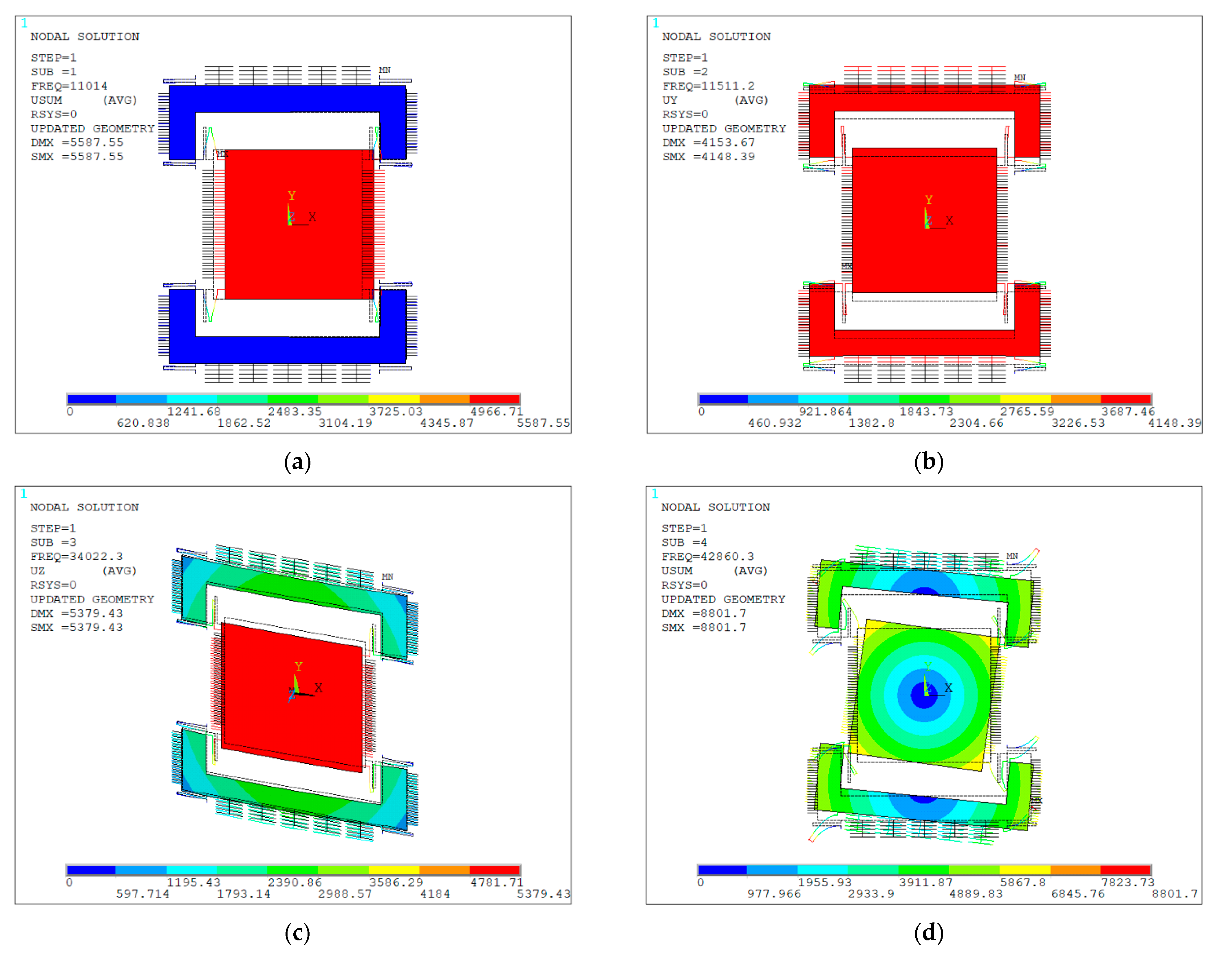
With the objective of determining the drive- and sense-mode resonant frequencies and eigen mode shapes for the proposed gyroscope design, a FEM-based modal analysis is performed in ANSYS APDL module. The effect of electrostatic tuning on the MEMS gyroscope dynamic behavior is investigated by performing two different simulations: The first one is performed without applying any bias tension on tuning electrodes, while the second one is performed by applying an increasing bias tension until compensating the frequency difference between the two modes. Figure 6 shows the first four mode shapes of the MEMS gyroscope obtained without considering the electrostatic tuning effect. The first mode of the structure (Figure 6a) is related to drive mode, in which only the drive mass is moving along the -direction and the spring beams, which connect it to the sense frame, are bending in the same direction. This mode implies a purely in-plane deformation of the structure. Similarly, the second mode is described by an in-plane motion and is related to the sense mode (Figure 6b). When the device is subjected to an external angular velocity in the -direction, the sense frame moves together with the drive mass in the -direction due to the Coriolis force. The third out-of-plane (Figure 6c) and fourth in-plane (Figure 6d) modes are associated with the tilting of the mass and do not affect the operation of the gyroscope. The slight difference between the resonant frequency values related to the two modes is necessary to apply the electrostatic tuning for the compensation of the frequency mismatch due to foundry process uncertainties and environmental device operating variations. Table 3 shows the comparison of modal analysis results obtained through the analytical model and FEM analysis, and show a close agreement, which demonstrates the accuracy of the developed analytical model for the proposed gyroscope design.
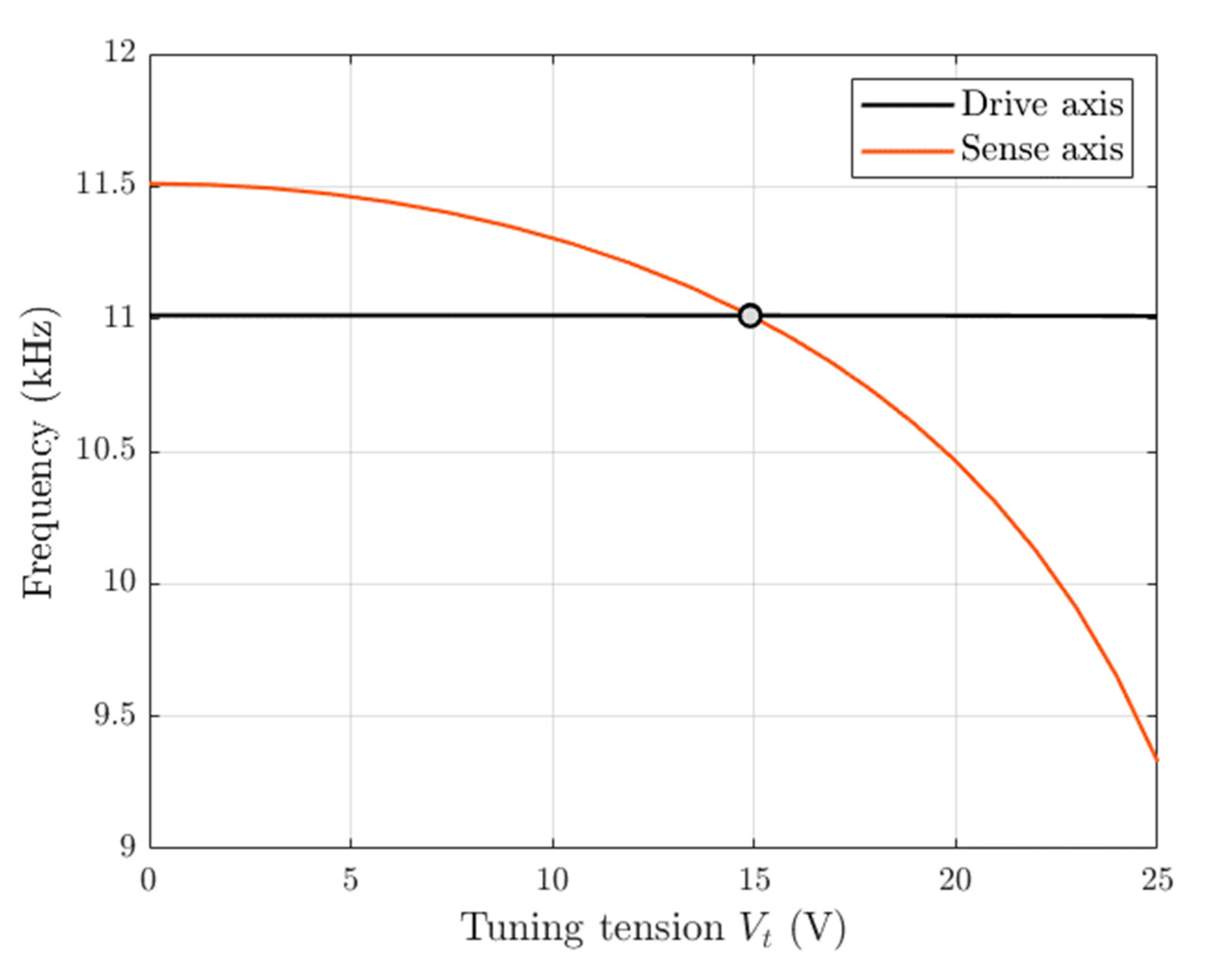
The electrostatic tuning application is considered performing a FEM-based modal analysis in ANSYS by applying an increasing tuning DC voltage on the tuning-comb structures. In this case, the followed first step is to proceed with a static analysis of the MEMS gyroscope with a DC voltage applied to the TRANS126 elements attached to moving tuning-comb fingers, and then perform a pre-stressed modal analysis on the MEMS gyroscope structure. The included pre-stress captures the effects of the applied voltage on the system frequency characteristic [25,26]. The program outputs are mechanical displacements and eigen frequencies with incorporated electrostatic effects. Figure 7 shows the frequency tuning characteristic of the drive and sense resonant modes of the proposed MEMS gyroscope structure as a function of the tuning voltage applied on the tuning electrodes. As expected, by increasing the DC tuning voltage applied to the fixed electrodes, the drive-mode resonant frequency remains constant at 11014 Hz, while the sense-mode resonance frequency is adjusted due to DC voltage-based tuning of the electrostatic spring constant. The resonant mode frequencies are perfectly matched at the DC tension of 14.903 V.
.
5.3. Dynamic Analysis
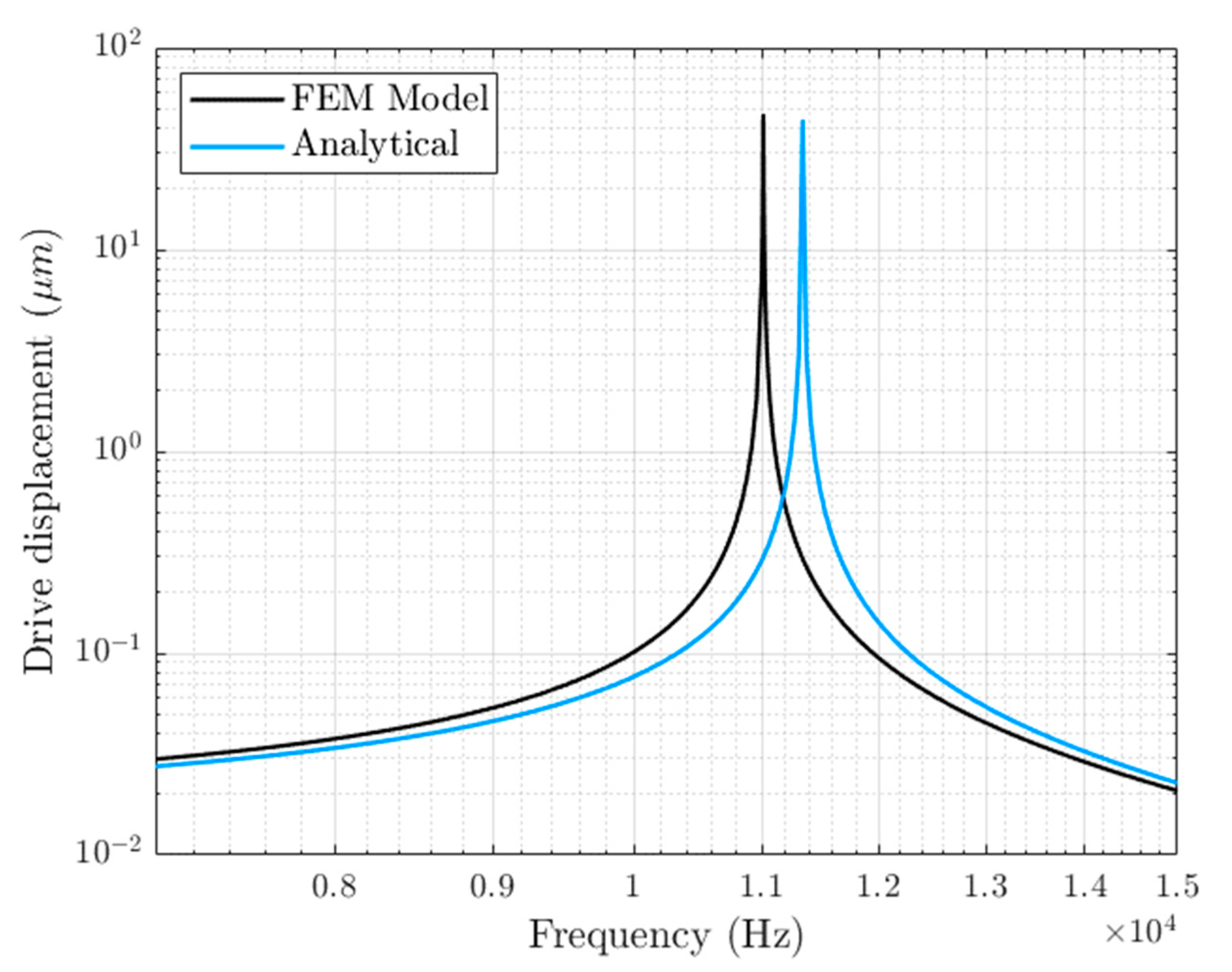
To study the dynamic frequency response of the MEMS gyroscope structure, a FEM-based harmonic analysis is performed in ANYS APDL module. The drive mass is excited by applying a DC voltage, superimposed on a small-signal AC voltage, to the comb-drive-based actuators, while an electrostatic DC tuning voltage is applied to tuning electrodes for the compensation of the frequency difference between the two modes. For frequency behavior simulation, a pre-stressed static analysis with actuation and electrostatic tuning DC voltage followed by a pre-stressed full harmonic analysis with an AC excitation is carried out. When the device is subjected to an angular velocity in the -axis, the sense-mode frequency response can be obtained activating the Coriolis effect in ANSYS. Figure 8 shows a comparison between the FEM-based and analytical frequency-based displacement amplitude of the gyroscope structure in the drive axis, obtained with a drive comb voltage of 50 V DC and 5 V AC. The results show that the FEM-based frequency response is slightly shifted in frequency compared with the one obtained analytically. At the corresponding drive resonant frequency , the FEM-based and analytical frequency response amplitude are 46.93 μm and 44.03 µm, respectively.
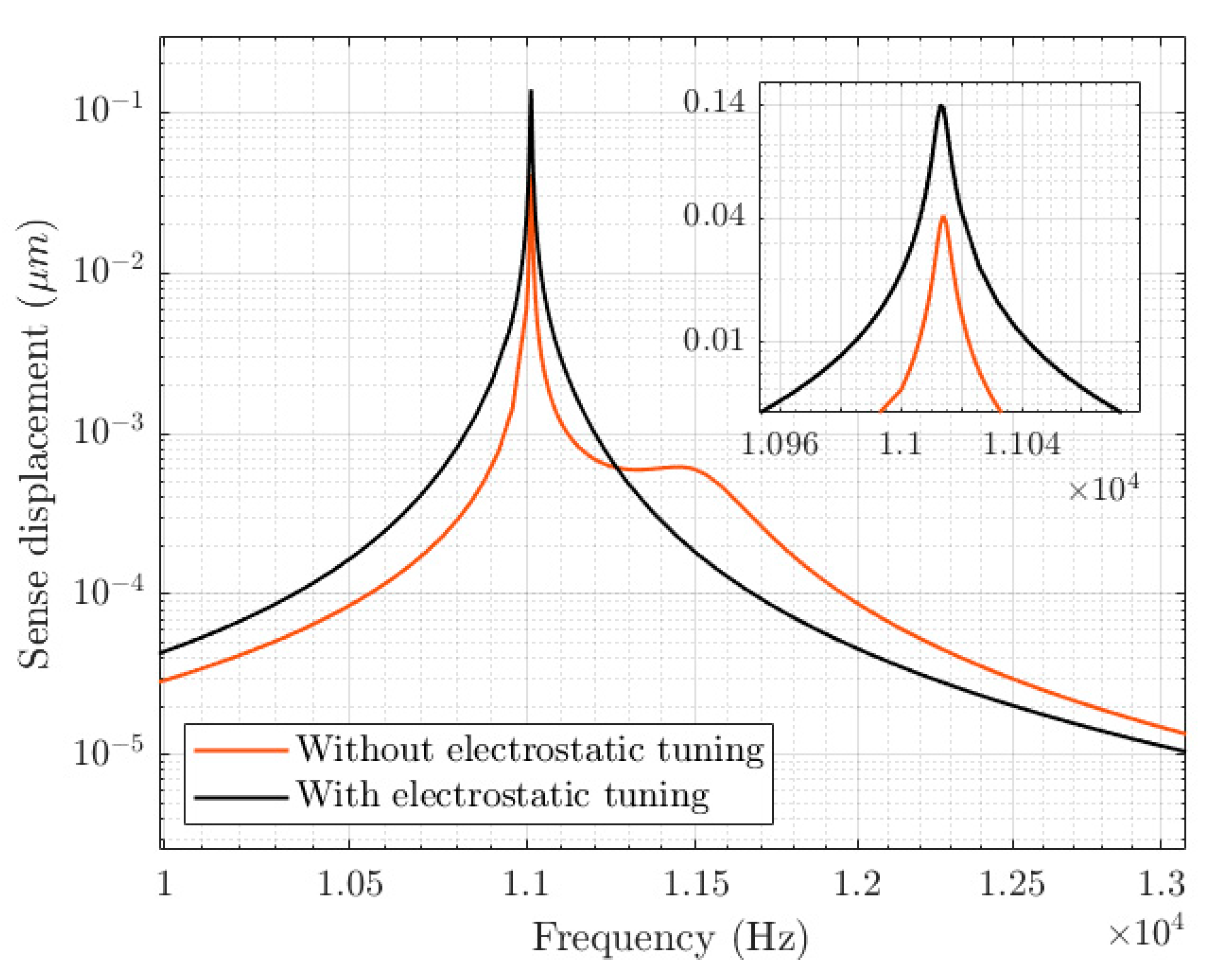
Figure 9 shows a comparison between the FEM-based frequency response amplitudes in the sense direction, obtained without and with the electrostatic tuning-voltage application and considering an angular velocity of .
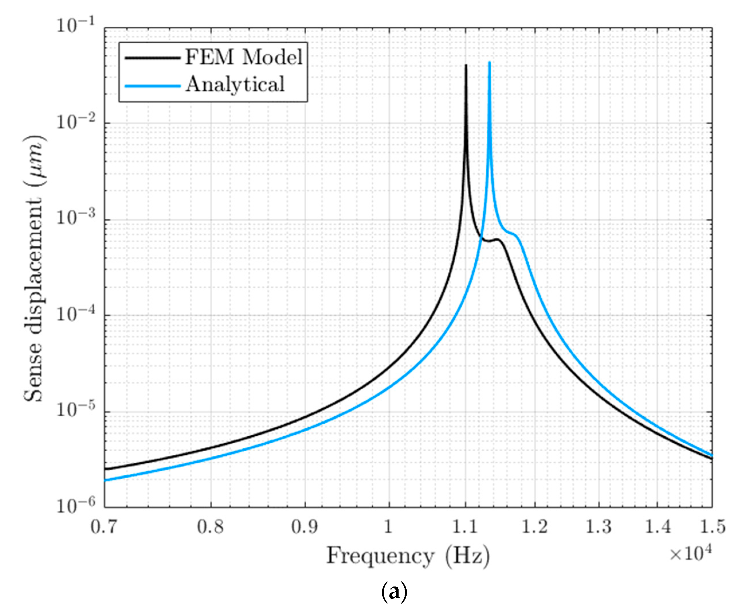
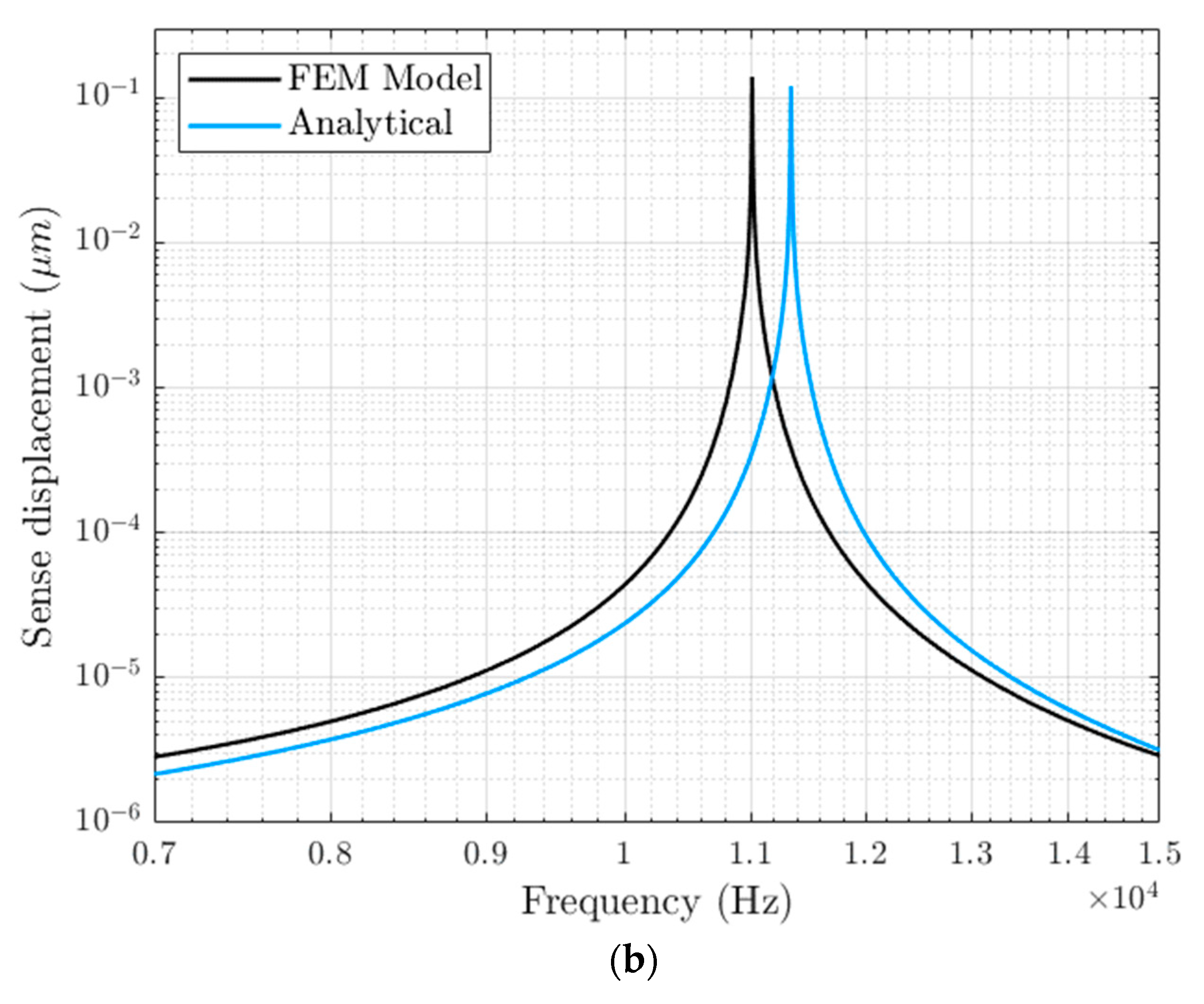
When no tuning tension is applied to tuning electrodes, the sense response has two distinct peaks due to the frequency mismatch between the modes, which results in a maximum oscillation amplitude of 0.0411 µm. When the tuning tension V guaranteeing the perfect match between resonant frequencies is applied, the sense response has only one peak with the maximum oscillation magnitude of 0.13930 µm. By considering a linear relation between the input angular velocity and the displacement in the sense direction, the mechanical sensitivity for the proposed MEMS gyroscope increases from 1.370 to 4.643 µm/deg/s, meaning that the tuning application allows an increase in the mechanical sensitivity by 238.9%. Figure 10 shows a comparison between FEM-based and analytical frequency response magnitude of the MEMS gyroscope structure in the sense direction obtained without (Figure 10a) and with (Figure 10b) the electrostatic tuning-voltage application. In both cases, the FEM-based and analytical frequency response amplitude are slightly shifted in frequency. The analytical drive and sense frame displacement in the sense direction corresponding to the rotation-induced Coriolis force is 0.0440 µm and the mechanical sensitivity is 1.467 µm/deg/s without the electrostatic tuning application, while in the case of a perfect match between modes the sense oscillation amplitude and mechanical sensitivity become 0.1205 µm and 4.017 µm/deg/s, respectively.
5.4. FEM Analysis of Temperature Variations on Structural Stability
The performance of the proposed MEMS gyroscope can be affected by operating-temperature variations because they can cause resonant frequency shift [25] of drive and sense modes, which may result in a drastic decrease in the output signal gain.
The Young’s modulus of the silicon structural material, which was used to design the proposed MEMS gyroscope, changes with temperature and this results in changes in the resonant frequency values. The analytical expression for the effect of operating temperature on Young’s modulus value of the silicon material is given as [27]:
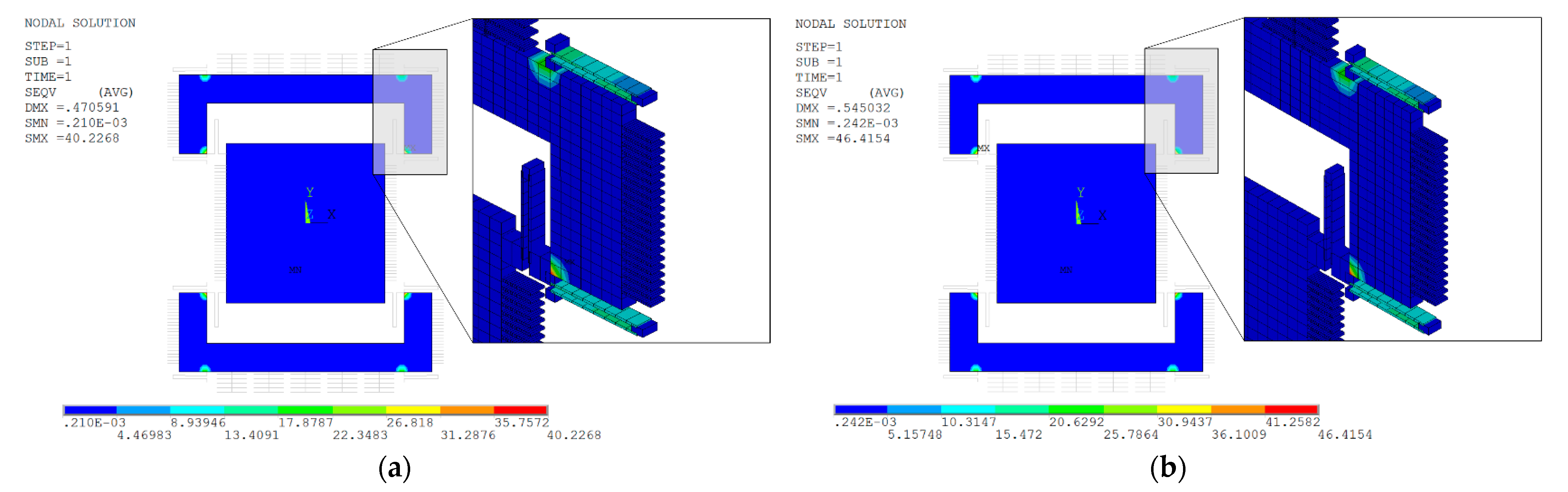
where is the Young’s modulus at reference temperature, is the temperature, and and are the constants that are calculated as 15.8 MPa and 317 K, respectively. The silicon Young’s modulus value varies from 169.03 to 168.93 GPa only in the MEMS gyroscope operational temperature values between −40 °C to 100 °C. Accordingly, the effect of temperature variation on Young’s modulus and, thus, on stiffness variation is in practice negligible over the desired operating temperature range. However, the device operating temperature from −40 °C to 100 °C may lead to thermal deformations, which are expansions and contractions in the microstructure. For the MEMS gyroscope design, these thermal deformations may eventually lead to a change in the air gap and structural planarity of the comb-drive actuators, electrostatic tuning combs and parallel plate-based capacitive sensors. In addition, temperature variations may result in thermal stresses. A FEM-based thermal analysis is performed in the ANSYS APDL module to analyze the resonant frequency changes due to thermal deformations and thermally induced stresses. First, a uniform temperature, varying in the range −40 °C to 100 °C, is assigned to all the structural nodes in the FEM model. A static analysis is then performed with pre-stress effects [26] turned on and considering the ambient temperature = 25 °C as a reference temperature. Figure 11a,b shows the thermally induced localized stresses resulting from the FEM-based static analysis, at −40 °C and 100 °C, respectively. In the region where the sensing spring beams are connected to the structure, there is a large concentration of thermal stress, while nearly no thermal stress is induced in the regions of driving spring beams and in the rest of the structure.
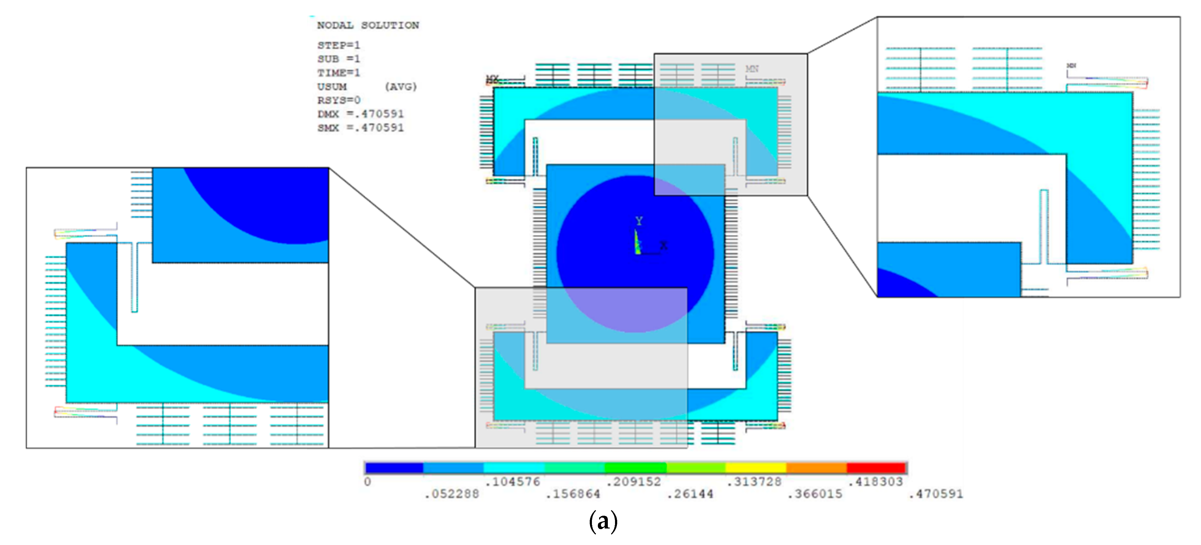
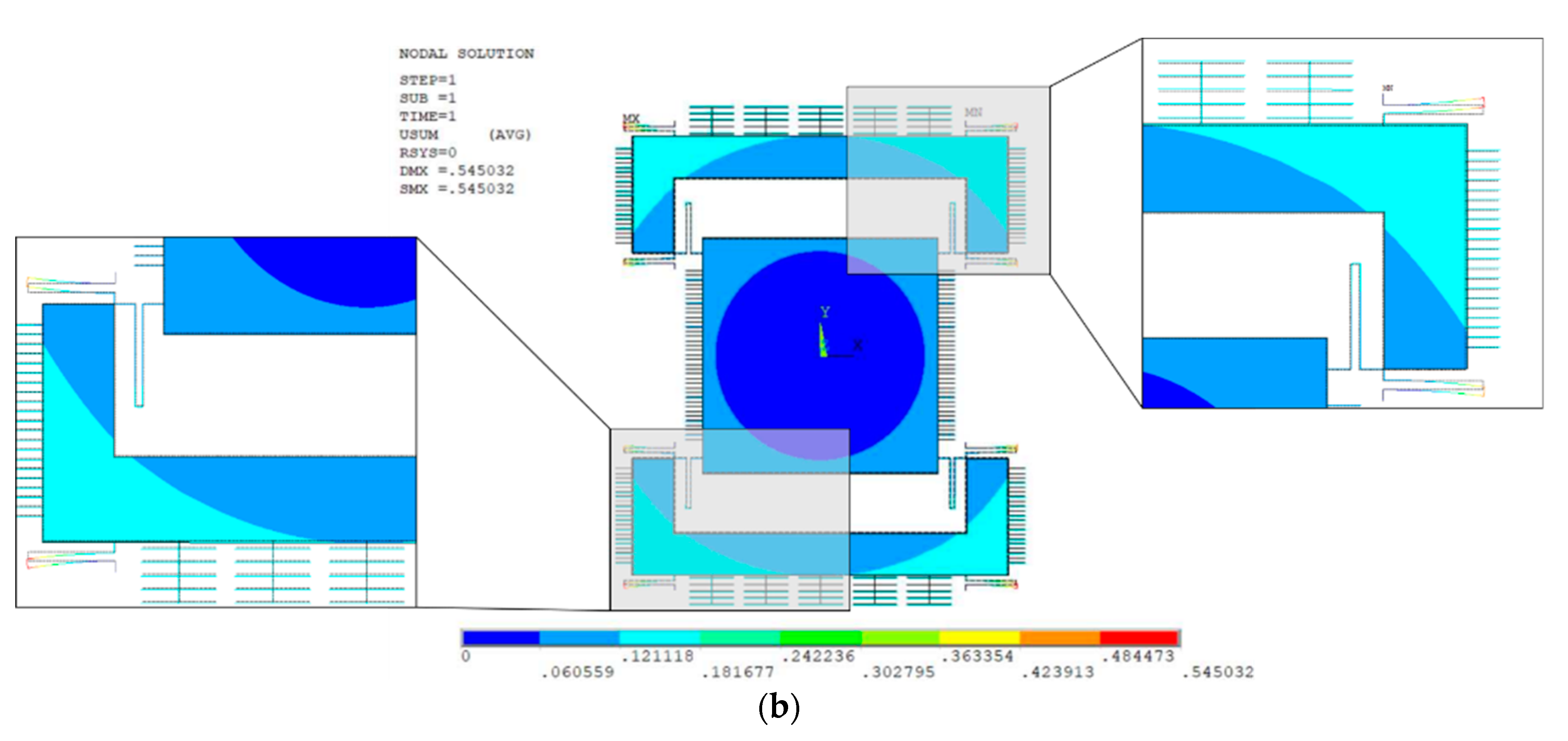
Figure 12a,b shows structural thermal deformation results at −40 °C and 100 °C, respectively. The thermal deformation at −40 °C results in a structural contraction with a maximum value of 0.47 µm in the sensing microbeams, while at 100 °C the gyroscope structure expands with a maximum expansion 0.545 µm in the sensing microbeams. These results show that although the mechanical thermal deformation in the sensing microbeams is high, the mechanical deformation in the drive and sense frame and in the driving microbeams is negligible, with a maximum value of only 0.104 µm at −40 °C and 0.121 µm at 100 °C.
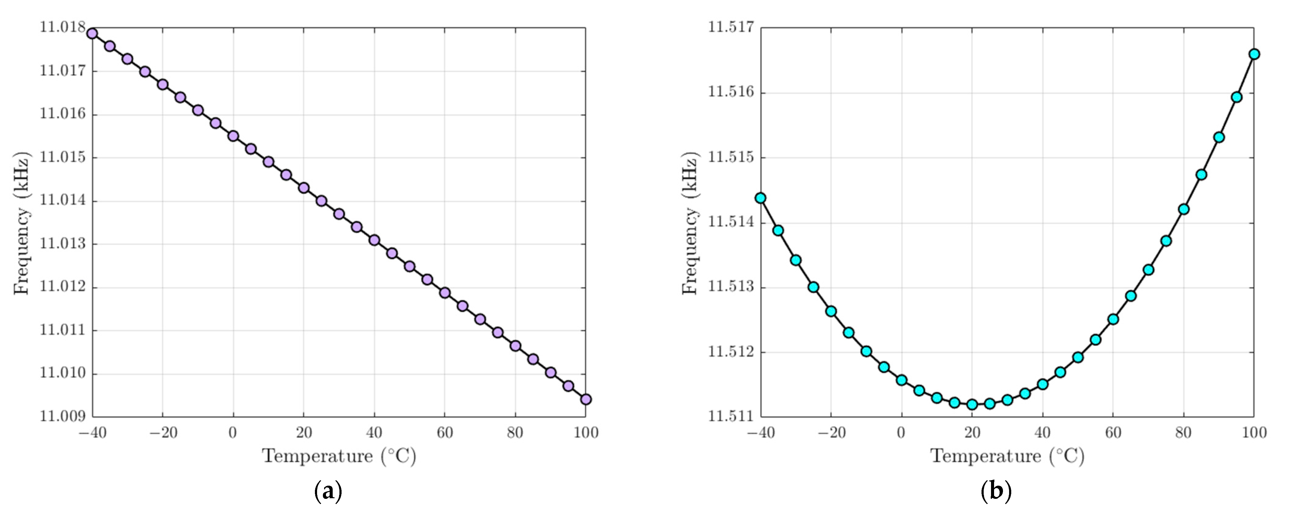
The static analysis is followed by a modal analysis. Prior to performing the modal analysis, in the FEM model the nodal coordinates are updated with the deflections from the previous static analysis and hence the pre-stress effects with the stresses stored from the static analysis are applied to the modal analysis. Figure 13 shows the FEM-based pre-stressed modal analysis results. The results show that the drive- and sense-mode resonant frequency values do not change in the same way as gyroscope operational temperature values between −40 °C and 100 °C, i.e., the drive-mode frequency (Figure 13a) always descends while the temperature increases, while the sense-mode frequency (Figure 13b) changes with a parabolic trend due to temperature operating variations. This is mainly due to the different thermal effects on drive and sense spring beams. The thermal analysis has shown that the sensing spring beams are subjected to a stress gradient while the stress is nearly negligible in the drive spring beams and in the rest of the structure. In addition, sensing spring beams are subjected to the highest thermal deformation.
5.5. FEM Analysis of Fabrication Process Tolerances on Structural Stability
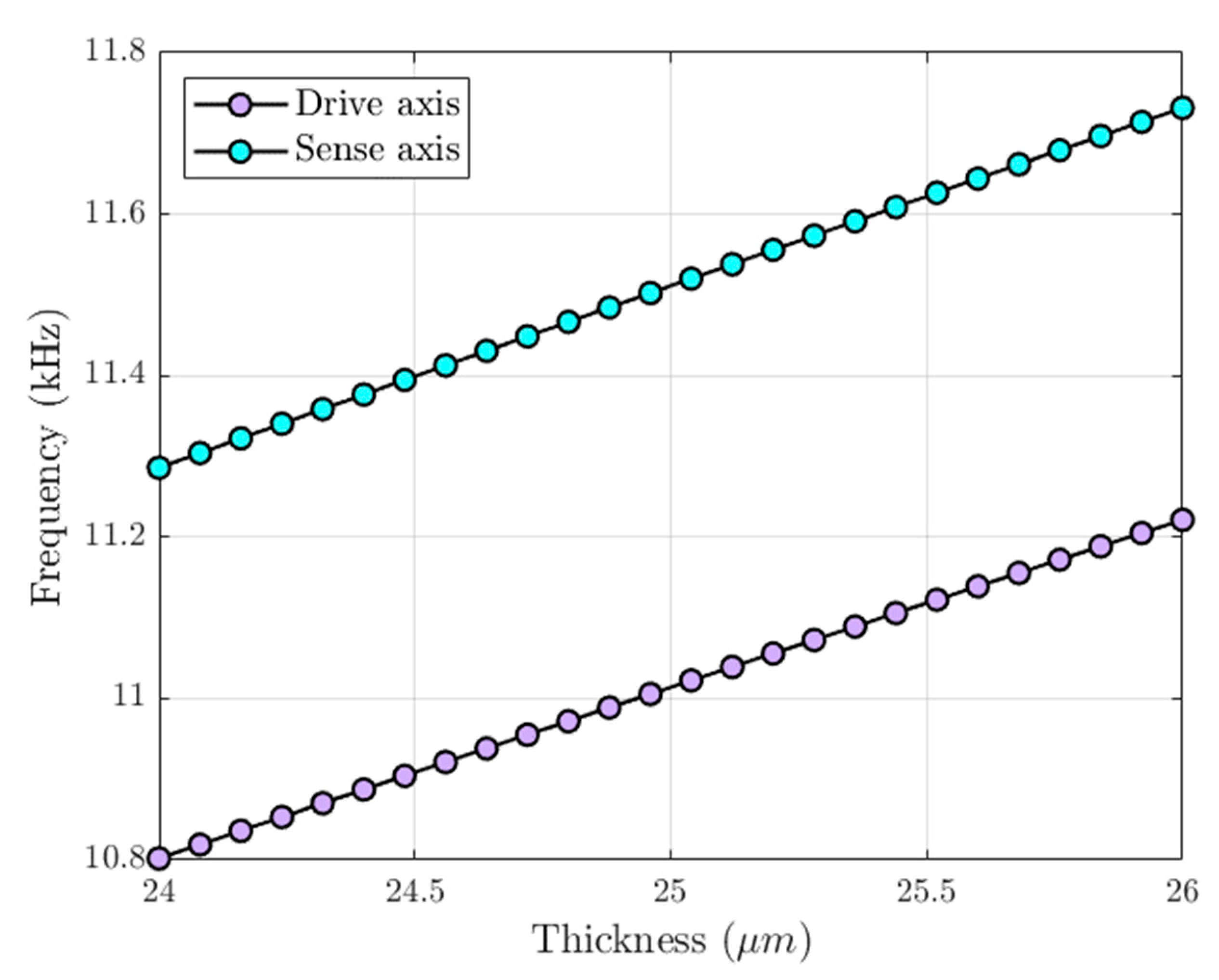
In addition to temperature variations, the microfabrication process tolerances can induce a frequency mismatch between drive and sense modes, which contributes to the decrease of the proposed MEMS gyroscope mechanical sensitivity. The SOIMUMPs is a relatively mature microfabrication process with tolerances of ±1 µm for the device thickness layer. A FEM-based modal analysis is performed in ANSYS APDL module considering a change in structural layer thickness with 25 µm ± 1 µm, i.e., the thickness of the mechanical spring varies between 24 µm and 26 µm. Figure 14 shows that the variation of the drive and sense resonant frequency values due to the thickness tolerances is nearly equal to 1.92% from the nominal values. The sense frequency remains higher than the drive one due to the initial mismatch with which the proposed MEMS gyroscope structure has been designed and, thus, the electrostatic tuning can be performed for the frequency compensation.
5.6. Compensation of Thermally Induced Frequency Mismatch through Electrostatic Tuning
The mismatch between the drive- and sense-mode frequency can cause the performance of the MEMS gyroscope to reduce drastically since even a slight mismatch can reduce the amplitude response of the resonant gyroscope significantly. As previously demonstrated in this paper, this error can be mitigated through the electrostatic frequency tuning, which allows tuning the sense-mode frequency to match the drive-mode one, guaranteeing the maximum possible mechanical sensitivity. Because thermal deformations induce air-gap variation between tuning-comb fingers that clearly influences the electrostatic tuning force generated by each fingers pair, a FEM-based modal analysis is performed in ANSYS APDL module to determine the exact value of tuning tension to compensate the mismatch between drive and sense modes for the desired operating temperature range. The exact tuning-voltage value is determined by applying the iterative approach of bisection method. At each iteration, the tuning voltage applied to the fixed electrodes is gradually increased and the drive- and sense-mode resonant frequencies are computed. If the driving frequency value is lower than the sensing one, it is concluded that the applied voltage is below the necessary voltage value to compensate the frequency mismatch. On the other hand, if the driving frequency is higher than the sensing one, it is concluded that the applied voltage is higher than the necessary voltage value. The interval between these two limits is continuously decreased until the voltage interval is smaller than a predetermined accuracy. Figure 15 provides the tuning voltage compensating the difference between the drive- and sense-mode resonant frequency in the gyroscope operational temperature values between −40 °C and 100 °C. As expected, the temperature increase with respect to the room temperature leads to an increase in the frequency mismatch and, thus, in the necessary tuning-voltage value .
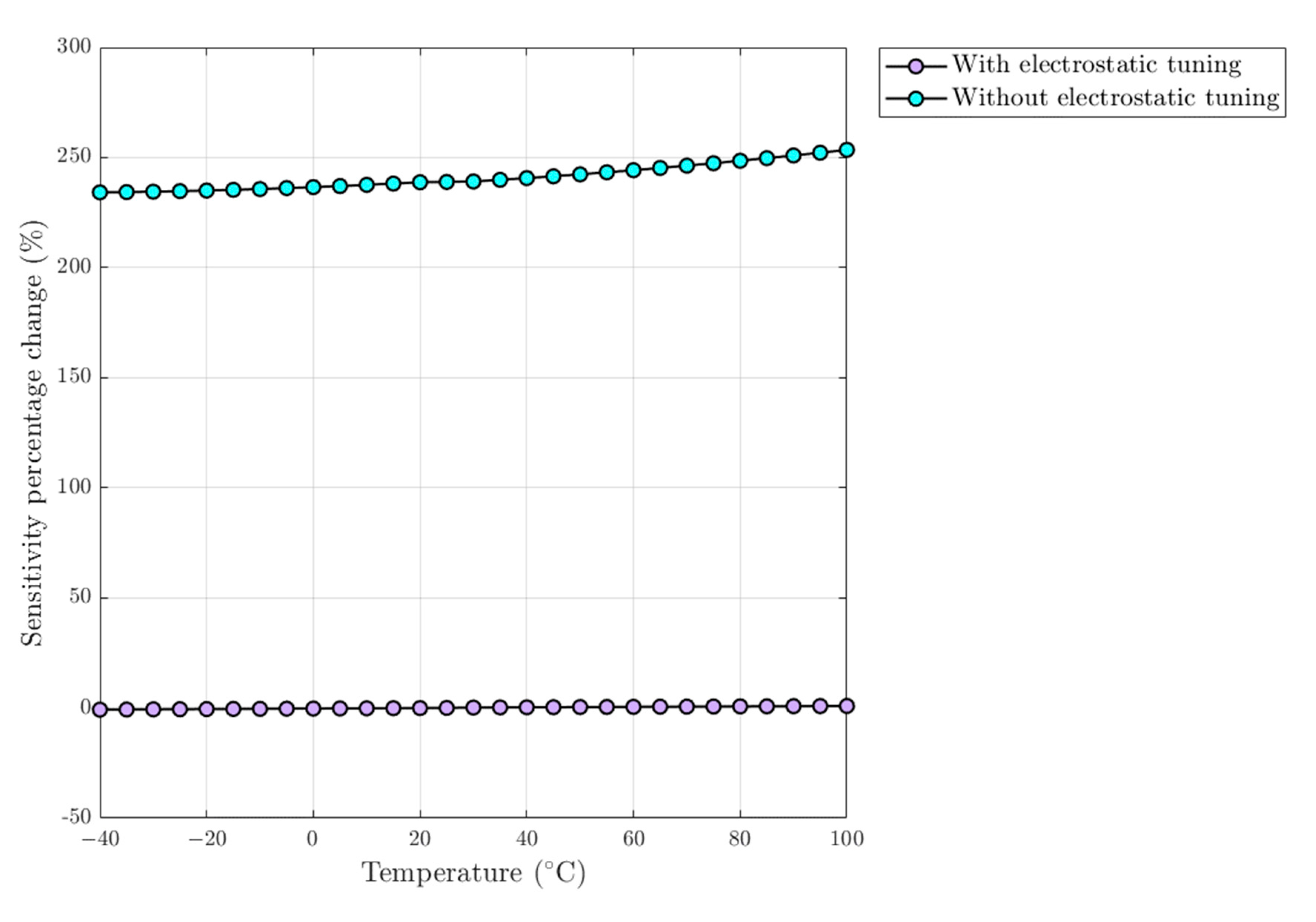
A mechanical sensitivity analysis is performed to investigate the effect of electrostatic tuning on the proposed MEMS gyroscope performances in the gyroscope operational temperature values between −40 °C and 100 °C. A FEM-based full harmonic analysis is performed neglecting the effect of temperature variation on the viscous damping coefficients. This means that mechanical sensitivity is only influenced by the frequency mismatch between the modes. Two different harmonic analyses are performed: the first with no tuning voltage applied on the tuning electrodes, and the second with the tuning voltage , which compensates the frequency mismatch between the modes. The procedure is first to assign a uniform temperature varying in the range of −40 °C to 100 °C to all structural nodes in the FEM model. The tuning voltage and the DC actuation voltage are respectively applied to TRANS126 element nodes connected to the tuning and drive combs’ moving fingers. A static analysis is performed with the pre-stress effects turned on and considering the ambient temperature of 25 °C. A full harmonic analysis is then carried out by applying an angular velocity = 300 °/s in the -axis and the AC actuation voltage with pre-stress effects due to applied DC voltages and temperature variations. Figure 16 shows the sensitivity percentage change computed with respect to the reference temperature. The results show that the compensation of frequency mismatch allows increasing the mechanical sensitivity and achieves high performance over the entire operating temperature range.
6. Conclusions
In this paper, a new structurally and thermally stable design of resonant mode-matched electrostatic -axis MEMS gyroscope that utilizes two separate masses for the drive and sense axis has been presented. The device, with an overall size of 1557 1816 , is designed following the foundry process limitations of relatively low cost and commercially available Silicon-on-Insulator (SOI)-based SOIMUMPs microfabrication process. The performance of the MEMS gyroscope design has been verified through detailed coupled-field electric-structural-thermal FEM-based analysis. The results have shown operating temperature variations and microfabrication process tolerances may cause a frequency mismatch between modes, which can cause the performance of the proposed MEMS gyroscope to reduce drastically since even a slight mismatch can reduce the amplitude response of the resonant gyroscope significantly. For the compensation of the frequency mismatch between modes, comb-drive-based electrostatic tuning has been implemented in the proposed design, which allows tuning the sense-mode frequency to approximate the drive-mode one, guaranteeing the maximum possible mechanical sensitivity. For a linear relation between the input angular velocity and the displacement in the sense direction and between the input angular velocity and the net capacitance change, in the case of a perfect match between drive and sense resonant frequency values, the mechanical sensitivity and the capacitance sensitivity values are 4.6433 µm/deg/s and 0.0560 fF/deg/s, respectively. The compensation of the initial frequency mismatch of 497 Hz due to the electrostatic tuning-voltage application of 14.903 V has resulted in an increase in the mechanical sensitivity of 238.9%.
Author Contributions
Conceptualization, A.S.; methodology, F.P., M.M.S.; software, F.P.; validation, A.S., M.M.S.; resources, A.S.; writing—original draft preparation, F.P., M.M.S., A.S.; supervision, A.S.; All authors have read and agreed to the published version of the manuscript.
Funding
This research received no external funding.
Institutional Review Board Statement
Not applicable.
Informed Consent Statement
Not applicable.
Conflicts of Interest
The authors declare no conflict of interest.
References
- Passaro, V.M.N.; Cuccovillo, A.; Vaiani, L.; De Carlo, M.; Campanella, C.E. Gyroscope Technology and Applications: A Review in the Industrial Perspective. Sensors 2017, 17, 2284. [Google Scholar] [CrossRef] [Green Version]
- Tian, L.; Niu, Y.; Cai, X.; Yang, Y. A cosine-fitting self-alignment method of MEMS-based inertial navigation system consisting of a skew FOG. IEEE Sens. J. 2020, 20, 1350–11356. [Google Scholar] [CrossRef]
- Botero-Valencia, J.; Marquez-Viloria, D.; Castano-Londono, L.; Morantes-Guzmán, L. A low-cost platform based on a robotic arm for parameters estimation of Inertial Measurement Units. Measurement 2017, 110, 257–262. [Google Scholar] [CrossRef]
- Xiao, D.; Zhou, X.; Li, Q.; Hou, Z.; Xi, X.; Wu, Y.; Wu, X. Design of a disk resonator gyroscope with high mechanical sensitivity by optimizing the ring thickness distribution. J. Microelectromech. Syst. 2016, 25, 606–616. [Google Scholar] [CrossRef]
- Hiller, T.; Pentek, Z.; Liewald, J.; Buhmann, A.; Roth, H. Origins and mechanisms of bias instability noise in a three-axis mode-matched MEMS gyroscope. J. Microelectromech. Syst. 2019, 28, 586–596. [Google Scholar] [CrossRef]
- Sharma, A.; Zaman, F.; Ayazi, F. A Sub-0.2°/hr Bias Drift Micromechanical Silicon Gyroscope with Automatic CMOS Mode-Matching. IEEE J. Solid-State Circ. 2009, 44, 1593–1608. [Google Scholar] [CrossRef]
- Trusov, A.A.; Schofield, A.R.; Shkel, A.M. Performance characterization of a new temperature-robust gain-bandwidth improved MEMS gyroscope operated in air. Sens. Actuators A Phys. 2009, 155, 16–22. [Google Scholar] [CrossRef]
- Verma, P.; Khan, K.Z.; Khonina, S.N.; Kazanskiy, N.L.; Gopal, R. Ultraviolet-LIGA-based fabrication and characterization of a nonresonant drive-mode vibratory gyro/accelerometer. J. Micro-NanoLith. MEM 2016, 15, 035001. [Google Scholar] [CrossRef]
- Saqib, M.; Mubasher Saleem, M.; Mazhar, N.; Awan, S.U.; Shahbaz Khan, U. Design and analysis of a high-gain and robust multi-DOF electro-thermally actuated MEMS gyroscope. Micromachines 2018, 9, 577. [Google Scholar] [CrossRef] [Green Version]
- Ding, X.; Jia, J.; Gao, Y.; Li, H. Mechanical and electrical noise in sense channel of MEMS vibratory gyroscopes. Sensors 2017, 17, 2306. [Google Scholar] [CrossRef] [PubMed] [Green Version]
- Balachandran, G.K.; Petkov, V.P.; Mayer, T.; Balslink, T. A 3-axis gyroscope for electronic stability control with continuous self-test. IEEE J. Solid-State Circ. 2015, 51, 177–186. [Google Scholar]
- Jia, J.; Ding, X.; Gao, Y.; Li, H. Automatic Frequency tuning technology for dual-mass MEMS gyroscope based on a quadrature modulation signal. Micromachines 2018, 9, 511. [Google Scholar] [CrossRef] [Green Version]
- Xu, L.; Li, H.; Ni, Y.; Liu, J.; Huang, L. Frequency tuning of work modes in z-axis dual-mass silicon microgyroscope. J. Sens. 2014, 2014, 891735. [Google Scholar] [CrossRef]
- Sharma, M.; Sarraf, E.H.; Cretu, E. A novel dynamic pull-in MEMS gyroscope. Procedia Eng. 2011, 25, 55–58. [Google Scholar] [CrossRef]
- Alper, S.E.; Azgin, K.; Akin, T. A high-performance silicon-on-insulator MEMS gyroscope operating at atmospheric pressure. Sens. Actuators A Phys. 2007, 135, 34–42. [Google Scholar] [CrossRef] [Green Version]
- Giner, J.; Maeda, D.; Ono, K.; Shkel, A.M.; Sekiguchi, T. MEMS gyroscope with concentrated springs suspensions demonstrating single digit frequency split and temperature robustness. J. Microelectromech. Syst. 2018, 28, 25–35. [Google Scholar] [CrossRef]
- Giannini, D.; Bonaccorsi, G.; Braghin, F. Size optimization of MEMS gyroscopes using substructuring. Eur. J. Mech. A Solids 2020, 84, 104045. [Google Scholar] [CrossRef]
- Iqbal, F.; Din, H.; Lee, B. Single Drive Multi-Axis Gyroscope with High Dynamic Range, High Linearity and Wide Bandwidth. Micromachines 2019, 10, 410. [Google Scholar] [CrossRef] [Green Version]
- Cowen, A.; Hames, G.; Monk, D.; Wilcenski, S.; Hardy, B. SOIMUMPs Design Handbook (Revision 8.0.). Available online: http://www.memscap.com (accessed on 30 November 2020).
- Somà, A.; De Pasquale, G. Numerical and experimental comparison of MEMS suspended plates dynamic behaviour under squeeze film damping effect. Analog Integr. Circuits Signal Process. 2008, 57, 213–224. [Google Scholar] [CrossRef]
- Veijola, T.; Turowski, M. Compact damping models for laterally moving microsctructures with gas-rarefaction effects. J. Microelectromech. Syst. 2001, 10, 263–273. [Google Scholar] [CrossRef]
- De Pasquale, G.; Veijola, T.; Somà, A. Modelling and validation of air damping in perforated gold and silicon MEMS plates. J. Micromech. Microeng. 2010, 20, 015010. [Google Scholar] [CrossRef]
- Mol, L.; Rocha, L.A.; Cretu, E.; Wolffenbuttel, R.F. Squeezed film damping measurements on a parallel-plate MEMS in the free molecule regime. J. Micromech. Microeng. 2009, 19, 074021. [Google Scholar] [CrossRef]
- Somà, A.; Saleem, M.M. Modeling and experimental verification of thermally induced residual stress in RF-MEMS. J. Micromech. Microeng. 2015, 25, 055007. [Google Scholar] [CrossRef]
- Ballestra, A.; Somà, A.; Pavanello, R. Experimental-Numerical Comparison of the Cantilever MEMS Frequency Shift in presence of a Residual Stress Gradient. Sensors 2008, 8, 767–783. [Google Scholar] [CrossRef] [PubMed] [Green Version]
- Somà, A.; De Pasquale, G.; Brusa, E.; Ballestra, A. Effect of residual stress on the mechanical behavior of microswitches at Pull-In. Strain 2010, 46, 358–373. [Google Scholar] [CrossRef]
- Bukhari, S.A.R.; Saleem, M.M.; Khan, U.S.; Hamza, A.; Iqbal, J.; Shakoor, R.I. Microfabrication Process-Driven Design, FEM Analysis and System Modeling of 3-DoF Drive Mode and 2-DoF Sense Mode Thermally Stable Non-Resonant MEMS Gyroscope. Micromachines 2020, 11, 862. [Google Scholar] [CrossRef] [PubMed]
Figure 1.
Schematic diagram of the proposed dual mass resonant micro-electro-mechanical systems (MEMS) gyroscope design with single proof mass and a decoupled sense mass: (a) Tuning-comb, (b) Comb-drive and (c) Sensing plate pairs.
Figure 1.
Schematic diagram of the proposed dual mass resonant micro-electro-mechanical systems (MEMS) gyroscope design with single proof mass and a decoupled sense mass: (a) Tuning-comb, (b) Comb-drive and (c) Sensing plate pairs.

Figure 2.
Lumped-parameter model for the dual mass MEMS gyroscope design.

Figure 3.
Sense Quality Factor variation: (a) effect of change in temperature in the range of −40 °C to 100 °C and ambient pressure of 101 kPa (b) effect of change in pressure the range of 1 kPa to 101 kPa and ambient temperature of 25 °C.
Figure 3.
Sense Quality Factor variation: (a) effect of change in temperature in the range of −40 °C to 100 °C and ambient pressure of 101 kPa (b) effect of change in pressure the range of 1 kPa to 101 kPa and ambient temperature of 25 °C.

Figure 4.
Meshed finite element method (FEM) model of the proposed MEMS gyroscope design.

Figure 5.
Setup of TRANS126 elements for the FEM-based electrostatic analysis of the proposed MEMS gyroscope.
Figure 5.
Setup of TRANS126 elements for the FEM-based electrostatic analysis of the proposed MEMS gyroscope.

Figure 6.
Eigen frequencies and the mode shapes for the proposed dual mass MEMS gyroscope (a) 1st mode (11,014 Hz) (b) 2nd mode (11,511 Hz) and (c) 3rd mode (34,022 Hz) and (d) 4th mode (42,860 Hz).
Figure 6.
Eigen frequencies and the mode shapes for the proposed dual mass MEMS gyroscope (a) 1st mode (11,014 Hz) (b) 2nd mode (11,511 Hz) and (c) 3rd mode (34,022 Hz) and (d) 4th mode (42,860 Hz).

Figure 7.
FEM-based resonant frequency tuning of the drive and sense resonant modes of MEMS gyroscope with applied tuning tension .
Figure 7.
FEM-based resonant frequency tuning of the drive and sense resonant modes of MEMS gyroscope with applied tuning tension .

Figure 8.
Comparison between the FEM-based and analytical frequency response amplitudes in the drive direction for the proposed dual mass MEMS gyroscope (logarithmic scale), obtained with 50 V DC and 5 V AC actuation voltage.
Figure 8.
Comparison between the FEM-based and analytical frequency response amplitudes in the drive direction for the proposed dual mass MEMS gyroscope (logarithmic scale), obtained with 50 V DC and 5 V AC actuation voltage.

Figure 9.
Comparison between the FEM-based frequency response amplitudes in the sense direction for the proposed dual mass MEMS gyroscope (logarithmic scale) obtained with a tuning voltage and V, with 50 V DC and 5 V AC actuation voltage and .
Figure 9.
Comparison between the FEM-based frequency response amplitudes in the sense direction for the proposed dual mass MEMS gyroscope (logarithmic scale) obtained with a tuning voltage and V, with 50 V DC and 5 V AC actuation voltage and .

Figure 10.
Comparison between the FEM-based and analytical frequency response amplitude in the sense direction for the proposed dual mass MEMS gyroscope (logarithmic scale), obtained with 50 V DC and 5 V AC actuation voltage and , (a) without electrostatic tuning, (b) with electrostatic tuning.
Figure 10.
Comparison between the FEM-based and analytical frequency response amplitude in the sense direction for the proposed dual mass MEMS gyroscope (logarithmic scale), obtained with 50 V DC and 5 V AC actuation voltage and , (a) without electrostatic tuning, (b) with electrostatic tuning.


Figure 11.
Thermally induced Von Mises stress in the proposed dual mass MEMS gyroscope (a) at −40 °C, (b) at 100 °C, with reference temperature of 25 °C.
Figure 11.
Thermally induced Von Mises stress in the proposed dual mass MEMS gyroscope (a) at −40 °C, (b) at 100 °C, with reference temperature of 25 °C.

Figure 12.
Structural thermal deformation in the proposed dual mass MEMS gyroscope (a) at −40 °C, (b) at 100 °C, with reference temperature of 25 °C.
Figure 12.
Structural thermal deformation in the proposed dual mass MEMS gyroscope (a) at −40 °C, (b) at 100 °C, with reference temperature of 25 °C.


Figure 13.
Resonant frequency variations in the gyroscope operational temperature values between −40 °C and 100 °C (a) Drive mode, (b) Sense mode, with reference temperature of 25 °C.
Figure 13.
Resonant frequency variations in the gyroscope operational temperature values between −40 °C and 100 °C (a) Drive mode, (b) Sense mode, with reference temperature of 25 °C.

Figure 14.
Drive and sense resonant frequency variations due microfabrication process tolerances.

Figure 15.
Tuning voltage compensating the mismatch between drive and sense modes for a temperature variation in the gyroscope operational temperature values between −40 °C and 100 °C, with a reference temperature = 25 °C.
Figure 15.
Tuning voltage compensating the mismatch between drive and sense modes for a temperature variation in the gyroscope operational temperature values between −40 °C and 100 °C, with a reference temperature = 25 °C.

Figure 16.
Mechanical sensitivity percentage change of the proposed dual mass MEMS gyroscope in the gyroscope operational temperature values between −40 °C and 100 °C, with and without the electrostatic tuning application.
Figure 16.
Mechanical sensitivity percentage change of the proposed dual mass MEMS gyroscope in the gyroscope operational temperature values between −40 °C and 100 °C, with and without the electrostatic tuning application.


Table 1.
Design parameters and their values for the proposed dual mass resonant MEMS gyroscope.
| Parameters | Value | Unit |
|---|---|---|
| Device size | ||
| Structural layer thickness | 25 | |
| Mass value of the drive mass ) | kg | |
| Mass value of the sense frame | kg | |
| Sensing plates length | 65 | |
| Sensing plates width | 4 | |
| Number of sensing plates pairs | 100 | - |
| Moving and fixed sensing plates overlap length | 55 | |
| Smaller sense gap size | 3 | |
| Larger sense gap size | 9 | |
| Drive comb pairs | 74 | - |
| Drive combs width | 4 | |
| Drive combs length | 50 | |
| Moving and fixed drive combs fingers overlap length | 40 | |
| Gap between drive combs | 3 | |
| Drive tuning comb pairs | 84 | - |
| Width of tuning combs | 4 | |
| Length of tuning combs | 50 | |
| Overlap length between the moving and fixed tuning combs fingers | 40 | |
| Gap between tuning combs | 3 |
Table 2.
Comparison between the analytical and FEM-based mechanical stiffness values.
| Mechanical Stiffness | Analytical Model (N/m) | FEM Model (N/m) |
|---|---|---|
| Drive mode () | 160.2 | 153.2 |
| Sense mode () | 320.5 | 298.6 |
Table 3.
Comparison of natural frequency values for the drive and sense modes obtained through analytical model and FEM model.
Table 3.
Comparison of natural frequency values for the drive and sense modes obtained through analytical model and FEM model.
| Mode Shape | Analytical Model (Hz) | FEM Model (Hz) | Error (%) |
|---|---|---|---|
| Drive axis | 11,348 | 11,014 | −2.94 |
| Sense axis | 11,757 | 11,511 | −2.09 |
Publisher’s Note: MDPI stays neutral with regard to jurisdictional claims in published maps and institutional affiliations. |
© 2021 by the authors. Licensee MDPI, Basel, Switzerland. This article is an open access article distributed under the terms and conditions of the Creative Commons Attribution (CC BY) license (http://creativecommons.org/licenses/by/4.0/).
Share and Cite
MDPI and ACS Style
Pistorio, F.; Saleem, M.M.; Somà, A. A Dual-Mass Resonant MEMS Gyroscope Design with Electrostatic Tuning for Frequency Mismatch Compensation. Appl. Sci. 2021, 11, 1129. https://doi.org/10.3390/app11031129
AMA Style
Pistorio F, Saleem MM, Somà A. A Dual-Mass Resonant MEMS Gyroscope Design with Electrostatic Tuning for Frequency Mismatch Compensation. Applied Sciences. 2021; 11(3):1129. https://doi.org/10.3390/app11031129
Chicago/Turabian StylePistorio, Francesca, Muhammad Mubasher Saleem, and Aurelio Somà. 2021. "A Dual-Mass Resonant MEMS Gyroscope Design with Electrostatic Tuning for Frequency Mismatch Compensation" Applied Sciences 11, no. 3: 1129. https://doi.org/10.3390/app11031129
Note that from the first issue of 2016, this journal uses article numbers instead of page numbers. See further details here.