
Bond Characteristics of a Deformed Steel Bar Embedded in Donut-Type Voided Slab

1
Division of Architectural Engineering, Daejin University, 1007, Hoguk-ro, Pocheon-si 11159, Korea
2
Department Fire and Disaster Prevention Engineering, Kyungnam University, Changwon 51767, Korea
*
Author to whom correspondence should be addressed.
Appl. Sci. 2022, 12(11), 5666; https://doi.org/10.3390/app12115666
Submission received: 2 May 2022
/
Revised: 24 May 2022
/
Accepted: 25 May 2022
/
Published: 2 June 2022
(This article belongs to the Section Civil Engineering)
Abstract
:In reinforced concrete (RC) structures, bond behavior between concrete and deformed steel bar (rebar) has a great effect on the structural behavior of members including voided slabs. According to previous research, bond behavior of a rebar in voided slabs is different from that in general RC slabs by the concrete inner cover formed between rebar and void. However, the bond characteristics of rebar in voided slabs have not been clearly verified yet. This study investigated the bond characteristics of rebar in the donut-type voided slab. Like other voided slabs, the donut-type void-shaper make concrete inner cover formed between rebar and void, and some part of the donut-type voided slab has smaller inner cover thickness than 2.5 db. Furthermore, inner cover thickness changes along the longitudinal rebar due to the shape of void. These were expected to affect the bond behavior of rebar in the donut-type voided slab. In this study, pull-out tests were performed to find out the effect of bond condition by the region due to voids. To this end, the donut-type voided slab was divided into three regions according to the shape of void, such as ‘Insufficient region’, ‘Transition region’, and ‘Sufficient region’. Main variables were inner cover thickness, embedded length, and bond location, which is affected by void shape. Bond characteristics of rebar in the donut-type voided slab were evaluated through comparison of bond stress–slip relationship, maximum bond strength, and bond stress distribution of each region. Test results showed that the average bond stress was found to be 25~50% lower than that of the general RC slab in the region of the inner cover thickness of 2.5 db, which was not satisfied due to void, and the bond stress–slip relationship and the bond stress distribution of the donut-type voided slab was also different from that of the general RC slab according to the type of bond region and inner cover thickness. In addition, the calculation method of bond strength of rebar in donut-type voided slab was proposed, which indicated that the error range between the estimated value and the experimental value was within 5%.
1. Introduction
1.1. Research Scope and Objectives
This study focused on the bond characteristics of a deformed steel bar (rebar) in the donut-type voided slab. The structural performance of reinforced concrete (RC) members including voided slabs mainly depends on a sufficient bond between the rebar and the surrounding concrete [1]. Like other voided slabs [2,3,4,5,6], the donut-type void-shaper (as shown in Figure 1) makes concrete inner cover formed between rebar and void, and some part of the donut-type voided slab has smaller inner cover thickness less than 2.5 times the diameter of the bar (). Furthermore, inner cover thickness changes along the longitudinal rebar due to the shape of void. These were expected to affect the bond behavior of rebar in the donut-type voided slab. Therefore, this study presented an experimental investigation to assess the effect of void on the bond characteristics of rebar in the donut-type voided slab. Moreover, the calculation method of bond strength of rebar in donut-type voided slab was suggested based on the test results. In this study, the slab with donut-type voids was divided into three bond regions (sufficient, transition, and insufficient regions) to identify the bond characteristics of the donut-type voided slab in each region, as indicated in Figure 2. Furthermore, to examine the influence of the inner cover between the void-shaper and the rebar in the slab on the bond performance of the deformed steel bar, an experimental study was conducted in which the inner cover thickness of the rebar was established as the variable.
1.2. Research Background
A voided slab is a slab with voids created by inserting void-shapers between the top and bottom layers of rebar in flat plate slabs [2]. By replacing the concrete inside the slab, which has a small influence on the flexural performance, with a void-shaper, the voided slab can maintain flexural strength and sound insulation as well as general RC slabs of the same thickness while reducing the weight by approximately 30%, thus being regarded as an effective structural system [2,3,4]. By applying the advantages of voided slabs, several voided slabs with various void shapes and details were developed, and many studies have been conducted to verify its structural performance in terms of the flexure, shear, and punching shear [3,4,5,6]. The donut-type voided slab is one of the developed voided slabs; Chung et al. [7] proposed a donut-type void as the optimum shape for a void-shaper by conducting analytical studies in which various shapes of void were used as variables, and they also evaluated the structural performance of the voided slab in terms of the flexure, shear, and punching shear through empirical and analytical studies [8,9,10,11].
Meanwhile, the bonding performance between the rebar and the concrete is a crucial factor in the deflection, crack, and tension stiffening effect of the slab [12,13]. According to Zuo et al. [14], bond behaviors between concrete and rebars are influenced by the diameter of the deformed steel bar, rib shape, rib spacing, the degree of the surface roughness, the cover thickness of the concrete and tensile strength of deformed steel bars. According to Abrishami et al. [15], bond failure mechanism between the concrete and the rebar is divided into pull-out failure and splitting failure, and bond strength of tensile rebar is greatly reduced when a splitting failure occurs. In addition, the splitting failure should be considered when the ratio of the rebar diameter to the minimum cover thickness is less than 2.5.
The donut-type void-shaper, which is mainly examined in this study, has an externally convex curved surface on the parts corresponding to corners and vertices of a rectangle and an inner hole connected through the center of the upper and bottom parts, as shown in Figure 1. As the void-shaper is placed in the web of the donut-type voided slab, a concrete cover is formed between the void-shaper and the rebar. Moreover, as the various cross-sections are generated depending on shapes of the void-shaper, the cover thickness between the void-shaper and the rebar varies along the longitudinal direction of the rebar as shown in Figure 2. The donut-type voided slab ensures a sufficient cover thickness in that the distance from the center of the rebar to the bottom surface of slab is more than 2.5 . However, as the inner cover thickness varies along the longitudinal direction of the rebar, a sufficient cover thickness of 2.5 is not satisfied in some part of the donut-type voided slab. Therefore, the rebar bond conditions of the donut-type voided slab are divided into three regions (sufficient, transition, and insufficient regions) as shown in Figure 2.
In the case of voided slabs, Avak [16] argued that the amount of the concrete surrounding the bottom tension rebar in a voided slab can decrease because of the void, subsequently reducing the bond strength of the rebar. The experimental results indicated that the maximum bond strength of the voided slab using round plastic balls as void-shapers decreased by 45% compared to that of a general RC slab. According to Kim et al. [17], the bond stress–slip relationship and the bond stress distribution of a steel wire in the deck type voided slab are different from that in general RC slabs by the concrete inner cover thickness, and the bond stress-strain model for one module of the deck type voided slab was proposed. However, the bond characteristics of rebar in voided slabs have not been clearly verified yet. Furthermore, the donut-type voided slab whose void-shaper has a different shape and is not in contact with the rebar has different bond conditions from those of the conventional voided slabs using round plastic balls as void-shapers and the deck-type voided slab. Therefore, further studies on the bond behavior of the donut-type voided slab are required to establish the bond characteristics of rebar in the donut-type voided slabs.
2. Bond Experiment
2.1. Experimental Variables
To identify the bond characteristics of the donut-type voided slab, a total of 13 specimens were produced by establishing the embedded length of the rebar, location of the bond region, and inner cover thickness as experimental variables in this study. The variable of the embedded length of the rebar is used to find the bond stress–slip characteristics and the bond stress distribution by region. To confirm the bond stress–slip characteristics by region, short bond specimens with the embedded lengths of less than 5 db were designed into three types depending on the void shape and location by region according to the longitudinal direction of the deformed steel bar, as shown in Figure 3a–c. Long bond specimens with the embedded length of 270 mm, which included all three regions of the donut-type void-shaper, were also designed to calculate the bond stress distribution of the rebar and verify the bond stress according to the longitudinal direction (refer to Figure 3d). Regarding the variable of the inner cover thickness, bond characteristics were confirmed by considering a total of three inner cover thicknesses including the clear inner-cover thickness of the proposed donut-type voided slab of 10 mm, that of 26 mm which satisfies the sufficient cover thickness condition (2.5 ), and that of 0 mm in which the rebar is in contact with the void-shaper. The details of test specimens are demonstrated in Table 1.
2.2. Material Experiment
The specified design strength of the concrete used in this experiment is 30 MPa, and the mixing ratio of concrete is described in Table 2. The concrete and deformed steel bars used in this test were evaluated by material test. A total of 12 cylinders with diameter of 100 mm and height of 200 mm were produced and cured under the same conditions provided for the specimens. A concrete strength test was performed just before the pull-out test, and the average strength of the 12 cylinders was found to be 29.5 MPa, which was almost similar to the specified design strength of 30 MPa. In terms of the deformed steel bar used in the bond experiment, D13 deformed bar of SD500 was used to measure the bond failure of the specimen. The strength evaluation of D13 deformed bar was performed by producing a specimen for the deformed bar tension test, and the test results are demonstrated in Table 3.
2.3. Production of Specimens
The specimen was produced according to KS F 2441 [18], and the specimen was produced based on the bottom rebar, which was the main tension reinforcement bar in the donut-type voided slab. With regard to the void-shaper used to produce the specimen, the previously produced donut-type void-shaper was divided in half to produce the void side in the slab. The details of the specimen are described in Figure 3. Strain gauges were attached on the long bond specimen by region to verify the bond strain distribution in the entire region in which the void-shaper was installed as shown in Figure 3d. To minimize the influence of the bond surface, the strain gauge was attached on the side rib of the deformed steel bar. Moreover, to decrease the influence of the compressive force of the bearing surface that can be generated in the pull-out test, the non-bond region, which was 5 from the loaded end, was formed using PVC pipe. Formwork of specimens was separated three days after the concrete placement, and the specimens were cured for 28 days before the experiment.
2.4. Experimental Method
In the experiment, as shown in Figure 4, the hardware for loading were produced, and the deformed steel bar was locked with a double-helix coupler while pull-out of the deformed steel bar was performed using a 500 kN screw jack. To reduce the compressive force that occurred between the specimen and bearing plate in the pull-out experiment, the hole of 2.5 was created in the bearing plate adjacent to the deformed steel bar. A rubber pad was also installed between the specimen and bearing plate to decrease the frictional force. To identify the clear slip between the deformed steel bar and concrete, the relative displacement between the protruding deformed steel bar at the free end and the concrete surface of the free end was measured. Moreover, the minimum slip of the deformed steel bar was found to reach 2.5 mm by installing 2 linear variable differential transducers (LVDTs) on the loaded end, and eccentricity during the experiment was measured. In addition, to ensure the accuracy of the experiment, experimental values were calibrated by installing a total of 6 LVDTs on the screw jack and hardware and measuring their displacement during the experiment as shown in Figure 5. The displacement control was performed at a loading rate of 0.6 mm/min according to KS F 2441 [18], and loads were applied until bond failure occurred, and the residual bond stress was confirmed in the specimen.
3. Experimental Results and Analysis
3.1. The Bond Stress–Slip Relationship of the Donut-Type Voided Slab
Table 4 and Table 5 and Figure 6, indicating the changes of the bond stress–slip relationship by inner cover thickness according to bond regions is depicted. The bond stress of the entire specimens increased by the initial chemical adhesive strength until slip occurred, and when slip occurred, the typical bond behavior in which the bond stress gradually increased due to interlocking between the rib of deformed steel bar and concrete was observed. However, the residual bond stress and failure behavior after the maximum bond stress varied according to the inner cover thickness and bond regions. As shown in Figure 6c, the GB-50-26 series specimen, which ensured sufficient inner cover thickness (2.5 ), showed similar maximum bond stress regardless of the location of bond regions. Moreover, after the maximum bond stress, the typical pull-out failure behavior in which the residual bond stress, which was maintained through the friction between the deformed steel bar and concrete, gradually decreased to 40–60% of the maximum bond stress that was observed. These results indicate that when the inner cover thickness of rebar was sufficient in the donut-type voided slab, the bond stress–slip relationship are same regardless of the bond regions. In other words, when the donut-type voided slab has sufficient inner cover thickness more than 2.5 , the bond characteristics of the rebar can be constant over the entire regions as in general RC slabs.
On the other hand, the results of the specimens of GB-50-10 and GB-50-0 series, which has insufficient inner cover thickness less than 2.5 , showed different tendency from that of the specimens of GB-50-26 series as shown in Figure 6a,b. The bond stress–slip relationship of theses specimens varied according to the bond regions and the inner cover thickness: the maximum bond strength was found to be high in the order of A-type, C-type, and B-type specimen when compared by the bond regions; and the maximum bond strength increased as the inner cover thickness increased. Figure 6a,b indicate the experimental results for the GB-50-10 and GB-50-0 series specimen whose clear inner cover thickness was 10 mm and 0 mm, respectively. The experimental results showed that the B-type specimens (GB-50-10-B and GB-50-0-B), which had a constant clear inner cover thickness at 10 mm and 0 mm, showed the lowest maximum bond strength of 10.95 MPa and 6.12 MPa, respectively. Regarding A-type and C-type specimens whose directions of thickness changes were symmetrical in the transition region in which the inner cover thickness changed, the maximum bond strength of the C-type specimen, which had the thin inner cover on the loaded end, is lower than that of the A-type specimen. The difference of A-type and C-type specimens was greater in the case of the GB-50-0 series specimen whose minimum inner cover thickness was lower. In the case of GB-50-10 series specimen whose clear inner cover thickness was 10 mm, the maximum bond strength of the C-type specimen, which had the thin inner cover on the loaded end, reduced by 15% compared to that of the A-type specimen as shown in Figure 6b. Meanwhile, in the case of GB-50-0 series specimen whose clear inner cover thickness was 0 mm, although the C-type specimen had same inner cover conditions of the concrete surrounding the rebar as those of the A-type specimen, the maximum bond strength of the former decreased by 50% according to the directions of inner-cover thickness change as shown in Figure 6a. These results determined that the C-type specimens with insufficient inner cover thickness had thin inner cover thickness at the loaded end where high bond stress occurs, and the farther it is from the loaded end, the more the inner cover thickness increased. Meanwhile, the A-type specimens with insufficient inner cover thickness similar to C-type specimens had thick inner cover thickness at the loaded end where high bond stress occurs, and the farther it is from the loaded end, the less the inner cover thickness decreased. In fact, in the case of C-type specimens with insufficient inner cover thickness, as the longitudinal crack occurred along the location of the rebar after the maximum bond stress, the splitting failure in which the residual bond stress rapidly decreased was generated.
3.2. Crack Pattern of the Donut-Type Voided Slab
Figure 7 shows the crack pattern of specimens according to the bond regions and inner cover thickness. As shown in Figure 7c, the GB-50-26 series specimen, which ensured sufficient inner cover thickness (2.5 ), did not show any crack regardless of the location of bond regions. However, the GB-50-10 and GB-50-0 series, whose clear inner cover thickness was insufficient (lower than 26 mm), showed a splitting crack that occurred along the rebar direction in the B-type and C-type specimens. Interestingly, A-type specimens of the GB-50-10 and GB-50-0 series did not show splitting cracks; nevertheless, it had insufficient inner cover thickness like C-type specimen. The difference between A-type and C-type specimens resulted from the direction of force at the rib of deformed steel bar. As shown in Figure 8, the bond force between the rib of deformed steel bar and concrete formed an angle of 45°. The A-type specimen had efficient concrete shape in order to resist 45° bond force, but the C-type specimen had inefficient concrete shape in order to resist 45° bond force. Moreover, the C-type specimens had thinnest inner cover thickness at the loaded end where high bond stress occurs. Thus, as shown in Figure 9, a splitting crack was generated at the transition region of the free end, and the concrete became spall due to the vertical component force that occurred at the rib of the deformed steel bar. These results indicate that when the inner cover thickness was insufficient, the bond stress–slip relationship varied according to the bond regions. Thus, the bond strength of the donut-type voided slab should be calculated by region considering the bond characteristics according to the inner cover thickness.
3.3. The Bond Stress Distribution of the Donut-Type Voided Slab
In terms of the bond stress distribution, the following Equations (1) and (2) were derived from the strain difference between two adjacent measurement points by strain gauges placed at a certain interval in the axial direction of the deformed steel bar. After the elastic region of the deformed steel bar (> 0.0028), the bond stress was calculated using the results of the deformed steel bar tension test () and Equation (2).
- : Elastic modulus of the deformed steel bar (MPa);
- : Diameter of the deformed steel bar (mm);
- : The deformed steel bar strength at the non-elastic region (kN);
- : The difference of the deformed steel bar strain between measurement points;
- : Distance between measurements points (mm).
Azizinamini [19] argued that when the embedded length of the rebar was long, the bond stress distribution varied according to the embedded length. He also insisted that the bond stress was generated mainly near the loaded end in the initial load step, and that the concrete gradually distributed the stress in the longitudinal direction of the deformed steel bar since the bond stress moved inwards as the load increased. However, bond conditions of the donut-type voided slab vary in the longitudinal direction of the rebar, as found in the experimental results of the short bond specimen, the bond stress–slip relationship changes. As such, to evaluate the bond strength by regions, the bond stress distribution by load step was investigated by using the entire-type specimen, which considered all the shapes of the void shaper. According to the deformed steel bar strain of the entire-type specimen by load step shown in Figure 10, the closer it was to the free end of the specimen, the more the deformed steel bar strain decreased because the concrete partially bore the tensile force of deformed steel bar through the bond strength between the deformed steel bar and concrete. As indicated in the cases of the S-270-S-E and GB-270-26-E, under the condition of an inner cover thickness of 2.5 , the deformed steel bar strain increased linearly as the load increased. On the contrary, regarding the deformed steel bar strain of the specimens of GB-270-0-E and GB-270-10-E whose inner cover thickness was not satisfied as 2.5 , the strain at the C and D points was found to be higher than that of S-270-S-E as loads increased, unlike the results shown in Figure 10c. It seems that the amount of tensile force on the deformed steel bar borne by the concrete decreased due to the low inner cover thickness between points B and D, thus leading to the increased slip of the deformed steel bar. Subsequently, the bond stress of the deformed steel bar that was to be borne by the concrete in the B–D region was transferred to the concrete in the D–E region, which was a transition region.
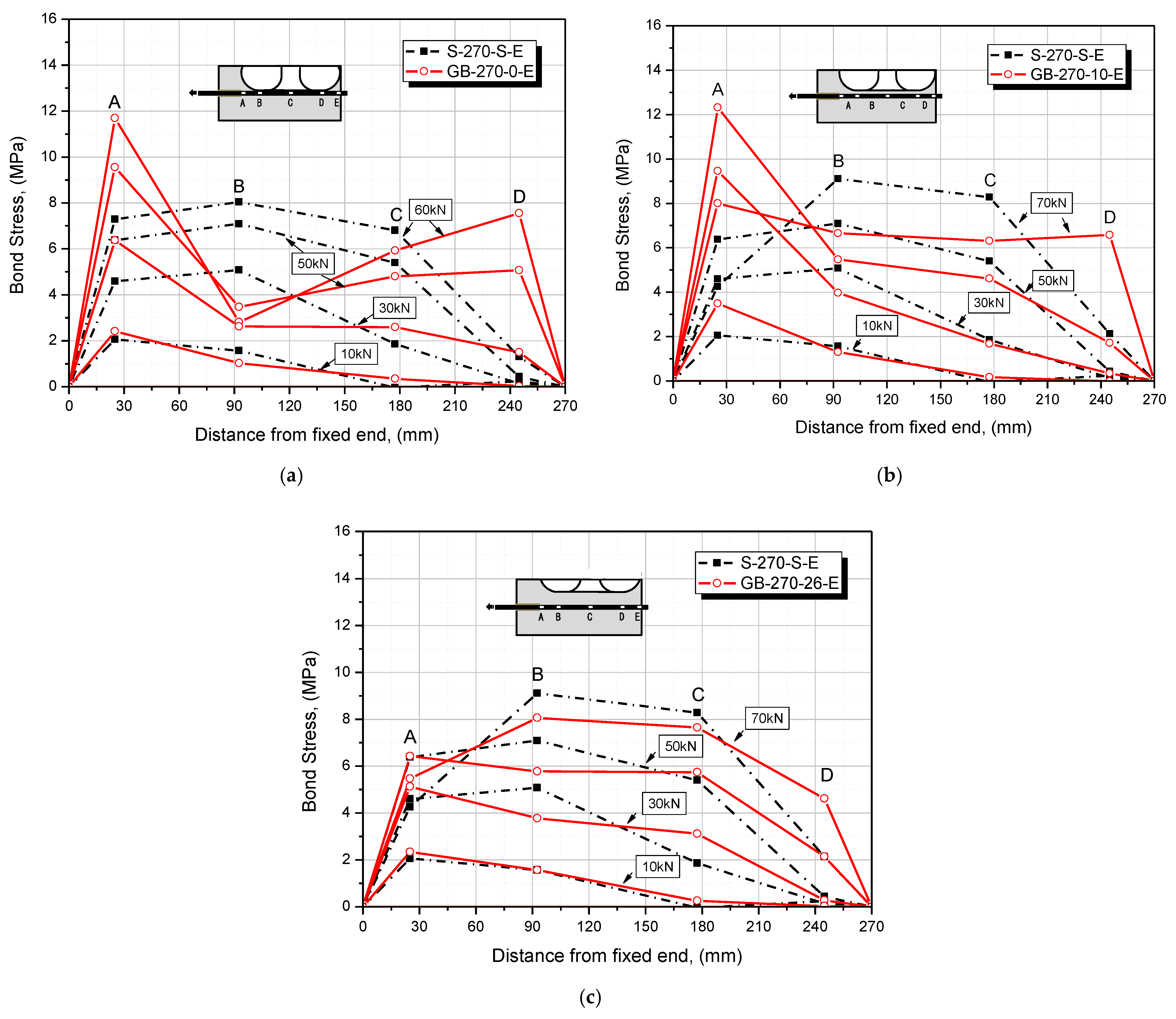
These behaviors can be confirmed more clearly through the bond stress distribution by load step shown in Figure 11. In the case of the GB-270-26-E specimen, whose inner cover thickness of 2.5 was satisfied, the bond stress distribution according to the load increase was quite similar to that of the S-270-S-E specimen. Furthermore, as shown in the study by Azizinamini [19], the maximum bond stress point was generated mainly near the loaded end in the initial load step, and the concrete was found to have distributed the stress in the longitudinal direction of the deformed steel bar gradually as the load increased. However, in the case of the specimens of GB-270-0-E and GB-270-10-E in which the minimum inner cover thickness of 2.5 was not satisfied, the bond stress was also generated mainly near the loaded end in the initial load step, whereas when the load increased, the bond stress decreased in the B–C region of minimum inner cover thickness. It was also found that the contribution rate of the D region in terms of the bond stress rapidly increased as the bond stress decreased in the B–C region. The results confirmed that the donut-type voided slab showed different average bond stresses by region according to the inner cover thickness. It was also verified that, when the inner cover thickness of 2.5 was not satisfied, the bond stress distribution was different from that of the general RC slab. Therefore, the results indicate that the bond strength of the voided slab should be calculated by region.
4. Calculation of the Bond Strength of the Donut-Type Voided Slab
4.1. The Average Bond Strength of the Conventional Methods
Zsutty [20] proposed the the equation for calculating the average bond stress of the deformed steel bar as shown Equation (3). In this equation, the minimum thicknesses of the cover surrounding the deformed steel bar and embedded length and diameter of deformed steel bar were considered in order to estimate the average bond stress of the deformed steel bar ().
- : The compressive strength of concrete (MPa);
- : Diameter of the deformed steel bar (mm);
- : The embedded length of a deformed steel bar (mm);
- : The minimum thicknesses of the cover surrounding the deformed steel bar [mm].
Zuo and Darwin [21] proposed the equation for calculating the ultimate bond force of the deformed steel bar as shown Equation (4). It is insisted that the maximum and minimum thicknesses of the cover surrounding the deformed steel bar were considered in order to estimate the ultimate bond force of the deformed steel bar ().
- : The compressive strength of concrete (MPa);
- : Diameter of the deformed steel bar (mm);
- : Cross sectional area of the deformed steel bar (mm2);
- : The embedded length of a deformed steel bar (mm);
- : The minimum thicknesses of the cover surrounding the deformed steel bar [mm];
- : The maximum thicknesses of the cover surrounding the deformed steel bar [mm].
In the CEB-FIP MC2010 [22], the equation for calculating the average bond strength of the deformed steel bar is not directly proposed, while the equation for calculating the development length () of the deformed steel bar is shown in Equation (5), which is derived based on Equation (6), which is the equation for calculating the tensile stress of the deformed steel bar () according to the bond length.
- : The compressive strength of concrete (MPa);
- : The yield strength of the deformed steel bar (MPa);
- : The average bond stress of the deformed steel bar (MPa);
- : Diameter of the deformed steel bar (mm);
- : Cross sectional area of the deformed steel bar (mm2);
- : The embedded length of a deformed steel bar (mm);
- : Transverse reinforcement index;
- : The minimum thicknesses of the cover surrounding the deformed steel bar (mm);
- : The maximum thicknesses of the cover surrounding the deformed steel bar (mm).
In these equations, the maximum and minimum thicknesses of the cover surrounding the deformed steel bar were considered in order to estimate the bond stress of the deformed steel bar. However, even in these equations for estimating the average bond strength of the deformed steel bar, the bond characteristics of the donut-type voided slab by region, for which minimum inner cover thickness varied according to the longitudinal direction of the deformed steel bar, were not reflected. Thus, as shown in Table 6, the bond strength of the donut-type voided slab was found to be underestimated when the average bond stress was calculated using Equations (3)–(6).
4.2. The Method of Calculating the Bond Strength of the Donut-Type Voided Slab
As the bond strength of the donut-type voided slab of each region (A, B, and C) was found to be different in the experimental results. The equation for calculating the bond strength considering the contribution to the bond strength by region, which was derived from the experimental results, was proposed to consider the bond characteristics by region, as shown in Equation (7). This equation is used to estimate the bond strength of the donut-type voided slab according to the entire embedded length by calculating the average bond stress by region based on the bond stress–slip relationship by region, which is derived through the short bond experiment.
- : Average bond stress of each region;
- : Embedded length of each region;
- : Total embedded length of re-bar.
The average bond stress of each region, , was obtained through the Rilem standard [23] method and the KS calculation method of the average bond stress [18]. The Rilem standard method calculates the average bond stress by calculating the average bond stress of each slip (0.01, 0.10, and 1.0 mm) in the bond stress–slip curve as shown in Equation (8). Similarly, in terms of the KS F 2441 method of calculating the average bond stress, it was also stated that the nominal average bond stress can be calculated by dividing the slipping distance at the loaded end into five equal intervals. At this time, the slipping distance at the loaded end is limited to be less than 0.25 mm. Thus, the average bond stress of each region was calculated using Equations (8) and (9) in this study, and the average bond strength of the donut-type voided slab specimen derived through the calculation is shown in Table 6.
- : the bond stress of each slip in the bond stress–slip curve;
- : the bond stress of each slip in the bond stress–slip curve.
As indicated in Table 6, the conventionally proposed equation for bond strength underestimated the bond strength of the donut-type voided slab by over 25% when the inner cover thickness was not 2.5 . However, when Equation (7), which was proposed considering the bond characteristics of each region, was applied, the estimated bond strength of the donut-type voided slab was highly accurate within the error range of 5%. In terms of the GB-270-26-E specimen, the value estimated through the proposed equation was found to be 20% higher than the experimental value. That is because the experiment was ended before the bond failure of the GB-270-26-E specimen due to the rupture of the deformed steel bar.
5. Conclusions
In this study, bond experiments were performed to evaluate the bond characteristics of the deformed steel bar in the donut-type voided slab. Based on the results, the equation for calculating the bond strength considering bond characteristics of each region according to the void shapes and inner cover thickness in the donut-type voided slab was also proposed. The findings of this study are as follows.
- (1)
- The bond stress–slip relationship of the donut-type voided slab was affected by the bond region according to the void shapes and inner cover thickness. Particularly, when the minimum inner cover thickness of 2.5 was not satisfied, the difference of the maximum bond strength by bond region was large, and the failure behavior varied.
- (2)
- The bond stress distribution of the donut-type voided slab was also different from that of the general RC slab according to the inner cover thickness. When the inner cover thickness of 2.5 was not satisfied due to the void, the average bond stress was found to be 25~50% lower than that of the general RC slab in the region of the minimum inner cover, and the bond stress was generated mainly at transition region in which sufficient inner cover thickness was ensured.
- (3)
- In the conventional method, which calculates the bond strength using the minimum cover thickness only, bond characteristics of the donut-type voided slab in regions where bond conditions varied along the longitudinal direction of the rebar were not reflected. Thus, it was found that the conventional method underestimated the bond strength of the donut-type voided slab.
- (4)
- In this study, the method of calculating the bond strength considering the bond characteristics of each region was proposed. The analytic results indicated that the error range between the estimated value and the experimental value was within 5%, thus confirming that the estimated bond strength of the donut-type voided slab was highly accurate.
Author Contributions
Original draft preparation and editing, J.-H.C. and H.-K.C.; Planning test program, H.-S.J. and H.-K.C.; performing tests and investigation, H.-S.J.; analyzing the results and reviewing the article, H.-K.C. and J.-H.C.; supervision and review writing, H.-K.C. All authors have read and agreed to the published version of the manuscript.
Funding
This work is supported by the Korea Agency for Infrastructure Technology Advancement (KAIA) grant founded by the Ministry of LAND, Infrastructure and Transport (22CTAP-C164325-02).
Institutional Review Board Statement
Not applicable.
Informed Consent Statement
Not applicable.
Data Availability Statement
Data is contained within the article.
Conflicts of Interest
The authors declare no conflict of interest.
References
- ACI Committee 408-03. Bond and Development of Straight Reinforcing Bars in Tension (ACI 408R-03); American Concrete Institute: Farmington Hills, MI, USA, 2003. [Google Scholar]
- BubbleDeck Technology. BubbleDeck Voided Flat Slab Solutions—Technical Manual & Documents; BubbleDeck UK: Jersey, UK, 2008. [Google Scholar]
- Dwivedi, A.K.; Raj, R.; Mishra, P.P.; Kadhane, M.; Mohabey, B. Voided Slab Design: Review Paper. Int. J. Res. Sci. Innov. 2016, 4, 220–226. [Google Scholar]
- Valivonis, J.; Jonaitis, B.; Zavalis, R.; Skuturna, T.; Šneideris, A. Flexural capacity and stiffness of monolithic biaxial hollow slabs. J. Civ. Eng. Mag. 2014, 20, 693–701. [Google Scholar] [CrossRef] [Green Version]
- Sagadevan, R.; Rao, B.N. Experimental and analytical investigation of punching shear capacity of biaxial voided slabs. Structures 2019, 20, 340–352. [Google Scholar] [CrossRef]
- Lee, Y.E.; Ryu, J.H.; Ju, Y.K.; Kim, S.D.; Kim, J.K. Experimental evaluation on punching shear of two-way void slab-to-column connection with TVS lightweight ball. J. Archit. Inst. Korea 2011, 27, 3–10. [Google Scholar]
- Chung, J.H.; Choi, H.K.; Lee, S.C.; Choi, C.S. An Analytical Study on the Optimal Hollow Spheres in a Biaxial Hollow Slab. J. Archit. Inst. Korea 2011, 27, 3–10. [Google Scholar]
- Kim, B.H.; Chung, J.H.; Choi, H.K.; Lee, S.C.; Choi, C.S. Flexural Capacities of One-way hollow slab with Donut type Hollow Sphere. Key Eng. Mater. 2011, 452–453, 773–776. [Google Scholar] [CrossRef]
- Chung, J.H.; Choi, H.K.; Lee, S.C.; Choi, C.S. One-way Shear Strength of Circular Voided Reinforced Concrete Floor Slabs. Proc. Inst. Civ. Eng. Struct. Build. 2015, 168, 336–350. [Google Scholar] [CrossRef]
- Chung, J.H.; Bae, B.I.; Choi, C.S.; Jung, H.S.; Choi, C.S. Evaluation of punching shear strength of voided slabs considering the effect of the ratio b0/d. Eng. Struct. 2018, 164, 78–81. [Google Scholar] [CrossRef]
- Chung, J.H.; Bae, B.I.; Choi, C.S.; Jung, H.S.; Choi, C.S. Two-Way Flexural Behavior of Donut-Type Voided Slabs. Int. J. Concr. Struct. Mater. 2018, 12, 339–351. [Google Scholar] [CrossRef]
- Lee, S.B.; Kang, S.Y.; Kim, S.S.; Lee, J.S. Experimental Evaluation of Effective Flexural Ridigity in Reinforced Concrete Beams Considering Tension Stiffening Effect. J. Korea Concr. Inst. 2005, 17, 1033–1042. [Google Scholar] [CrossRef]
- Kim, W.; Lee, K.Y. Crack Spacing in RC Tension Members Considering Cover Thickness and Concrete Compressive Strength. J. Korea Soc. Civ. Eng. 2018, 38, 193–202. [Google Scholar] [CrossRef]
- Zuo, J.; Darwin, D. Bond Strength of High Relative Rib Area Reinforcing Bars; SM Report 46; University of Kansas Center for Research: Lawrence, KS, USA, 1998. [Google Scholar]
- Abrishami, H.H.; Mitchell, D. Influence of Splitting Cracks on Tension Stiffening. ACI Struct. J. 1996, 93, 703–710. [Google Scholar]
- Avak, R. Topic: BubbleDeck-A New Type of Hollow-Body Ceiling; Report No. 9919586; Institute of Concrete: Lyngby, Denmark, 2001; pp. 6–9. [Google Scholar]
- Kim, H.H.; Choi, C.S. Bond Stress-Strain Predict Model with Inner Cover Thickness of Steel Wire Used in Void Deck Plate. J. Archit. Inst. Korea 2018, 34, 41–51. [Google Scholar]
- KS F 2441; Standard Test Method for Comparing Concrete on the Basis of the Bond Developed with Reinforcing Steel. Korean Agency for Technology and Standards: Eumseong-gun, Korea, 2010; pp. 1–7.
- Azizinamini, A.; Stark, M.; Roller, J.J.; Ghosh, S.K. Bond Performance of Reinforcing Bars Embedded in High-Strength Concrete. ACI Struct. J. 1993, 90, 554–561. [Google Scholar]
- Zsutty, T. Empirical Study of Bar Development Behavior. J. Struct. Eng. 1985, 111, 205–219. [Google Scholar] [CrossRef]
- Zuo, J.; Darwin, D. Splice Strength of Conventional and High Relative Rib Area Bars in Normal and High-Strength Concrete. ACI Struct. J. 2000, 97, 630–641. [Google Scholar]
- CEB-FIP. CEB-FIP Model Code 2010 First complete draft, Volume 1; fib Bulletin No. 55; CEB-FIP: Lausanne, Switzerland, 2010; pp. 239–246. [Google Scholar]
- Rilem-Fip-Ceb. Bond test for reinforcing steel: 1-Beam test (7-II-28 D). 2-Pullout test (7-II-128): Tentative recommendations. Mater. Struct. 1973, 6, 96–105. [Google Scholar]
Figure 1.
Donut-type void-shaper.

Figure 2.
Regions of the donut-type voided slab. Note—I: Insufficient region, T: Transition region, S: Sufficient region.
Figure 2.
Regions of the donut-type voided slab. Note—I: Insufficient region, T: Transition region, S: Sufficient region.
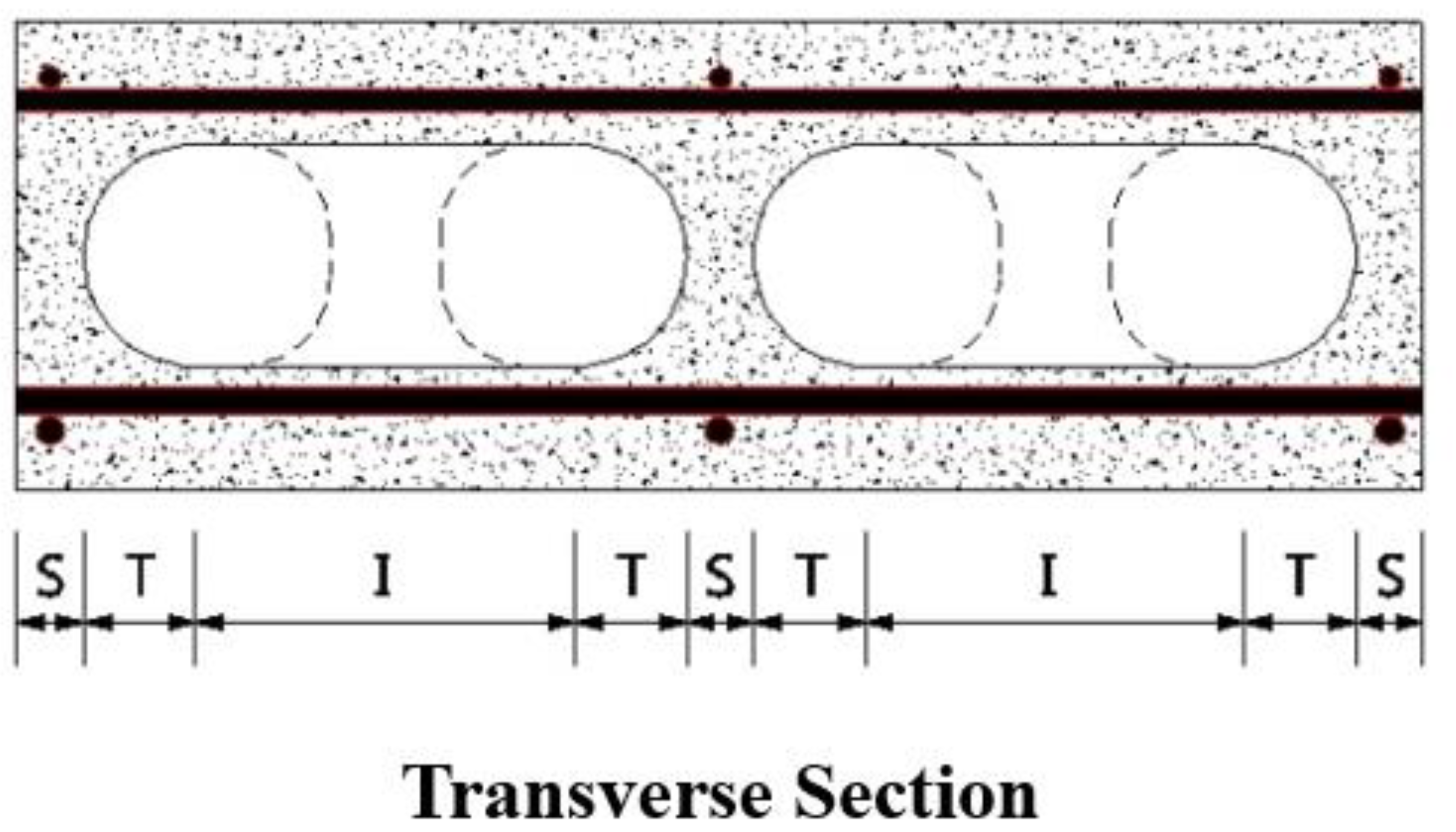
Figure 3.
Specimen details (unit; mm). (a) A-type; (b) B-Type; (c) C-Type; (d) Entire type.
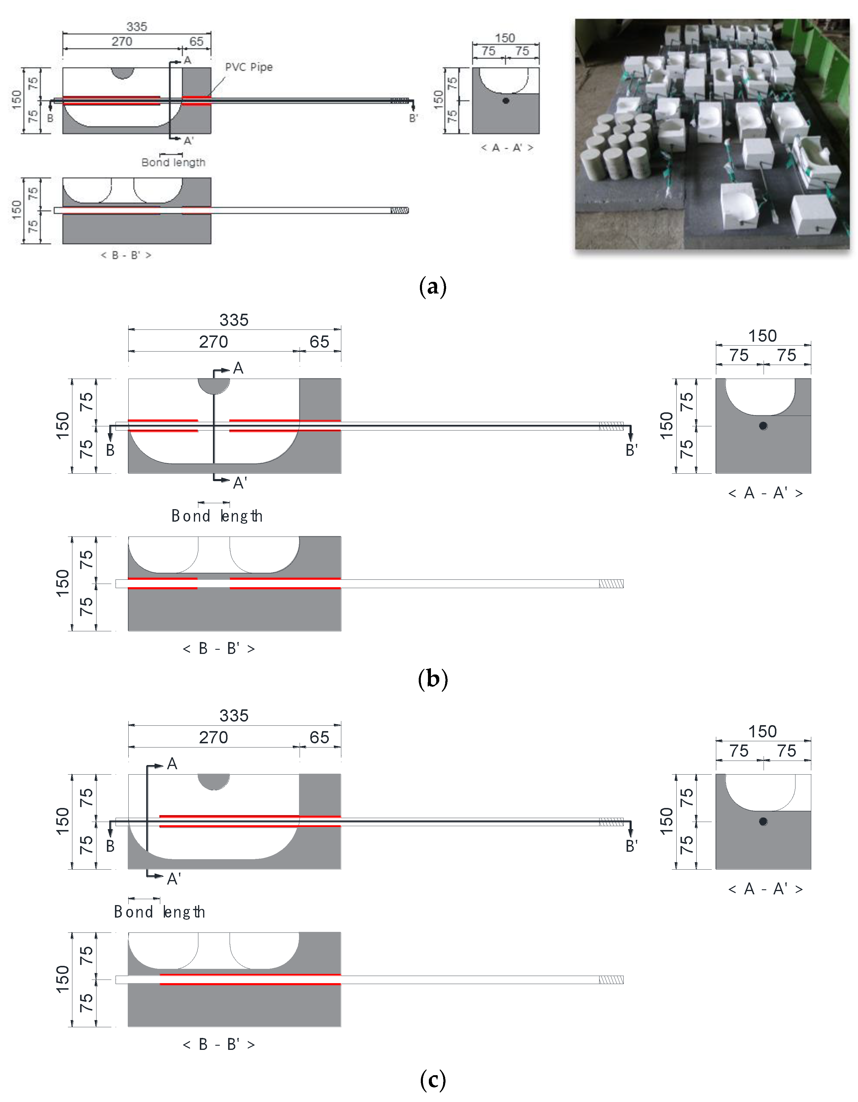
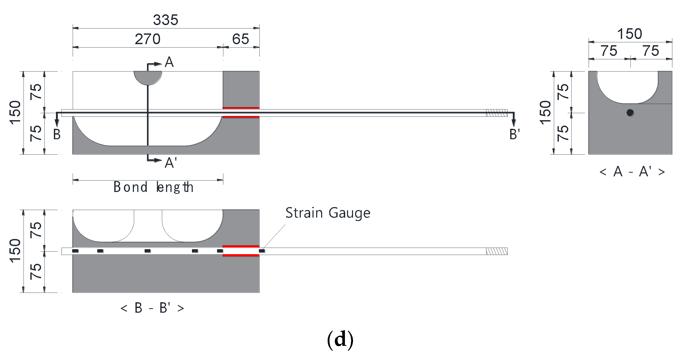
Figure 4.
Test setup.

Figure 5.
LVDT locations.
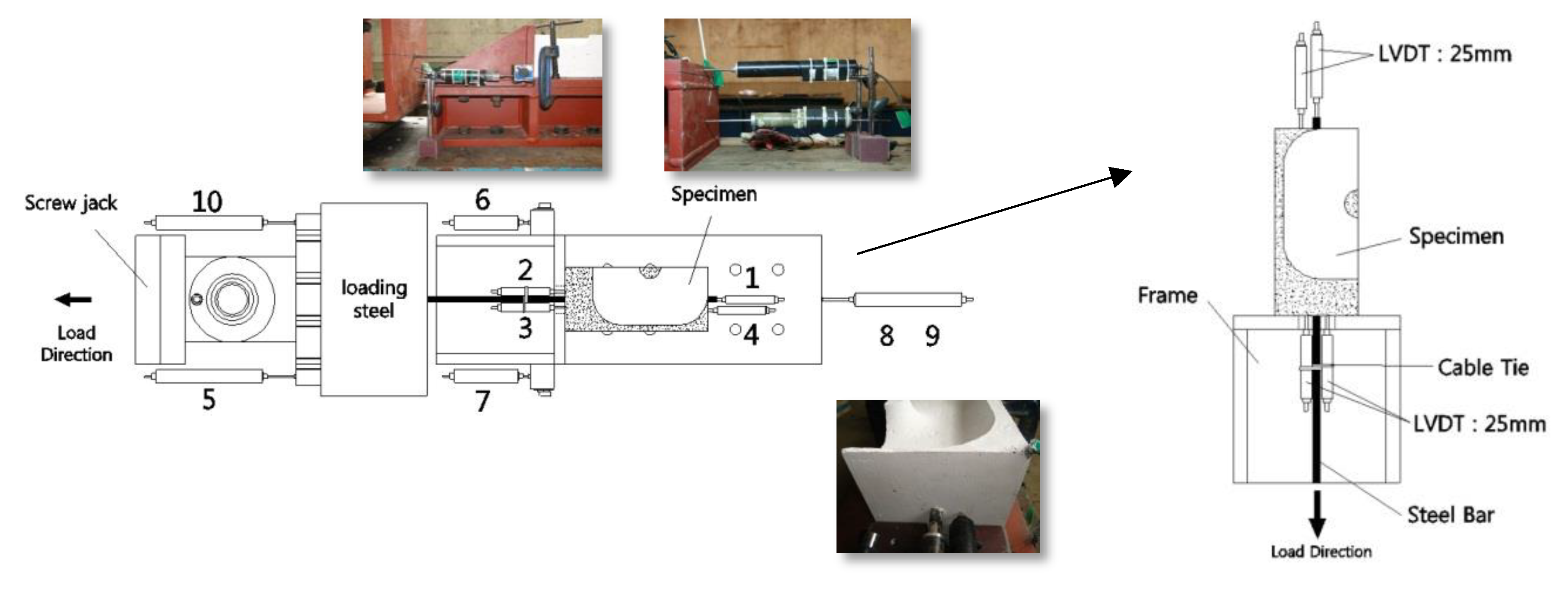
Figure 6.
Bond stress–slip curve. (a) Inner cover thickness: 0 mm; (b) Inner cover thickness: 10 mm; (c) Inner cover thickness: 26 mm.
Figure 6.
Bond stress–slip curve. (a) Inner cover thickness: 0 mm; (b) Inner cover thickness: 10 mm; (c) Inner cover thickness: 26 mm.
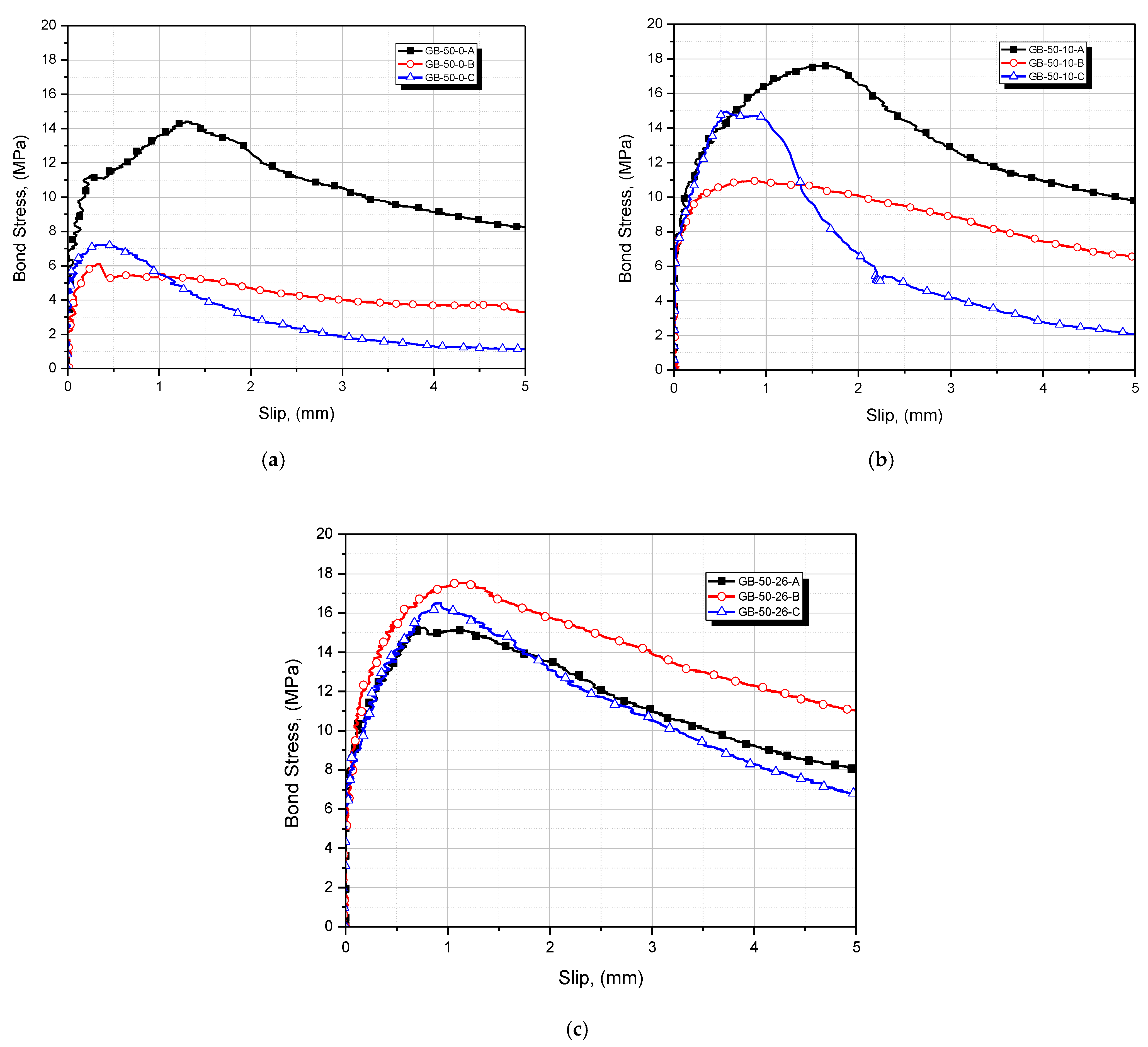
Figure 7.
Crack patterns. (a) Inner cover thickness: 0 mm; (b) Inner cover thickness: 10 mm; (c) Inner cover thickness: 26 mm.
Figure 7.
Crack patterns. (a) Inner cover thickness: 0 mm; (b) Inner cover thickness: 10 mm; (c) Inner cover thickness: 26 mm.
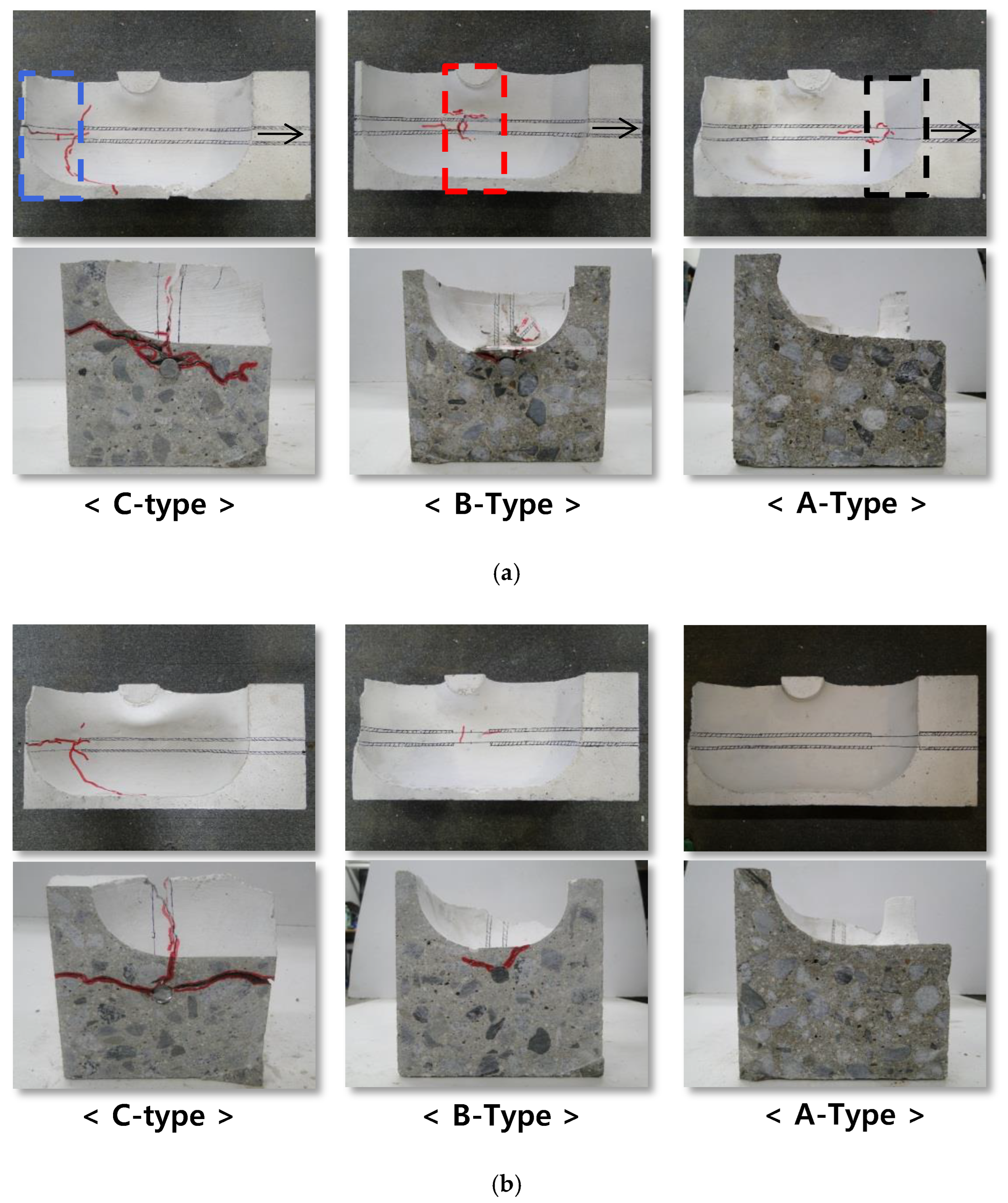
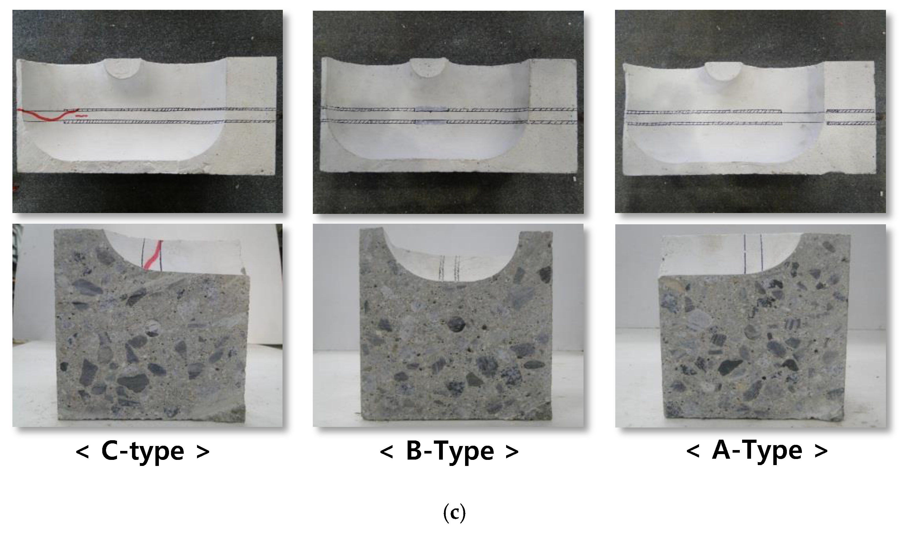
Figure 8.
The bond force by wedging action of deformed steel bar. (a) A-type specimen; (b) C-type specimen.
Figure 8.
The bond force by wedging action of deformed steel bar. (a) A-type specimen; (b) C-type specimen.
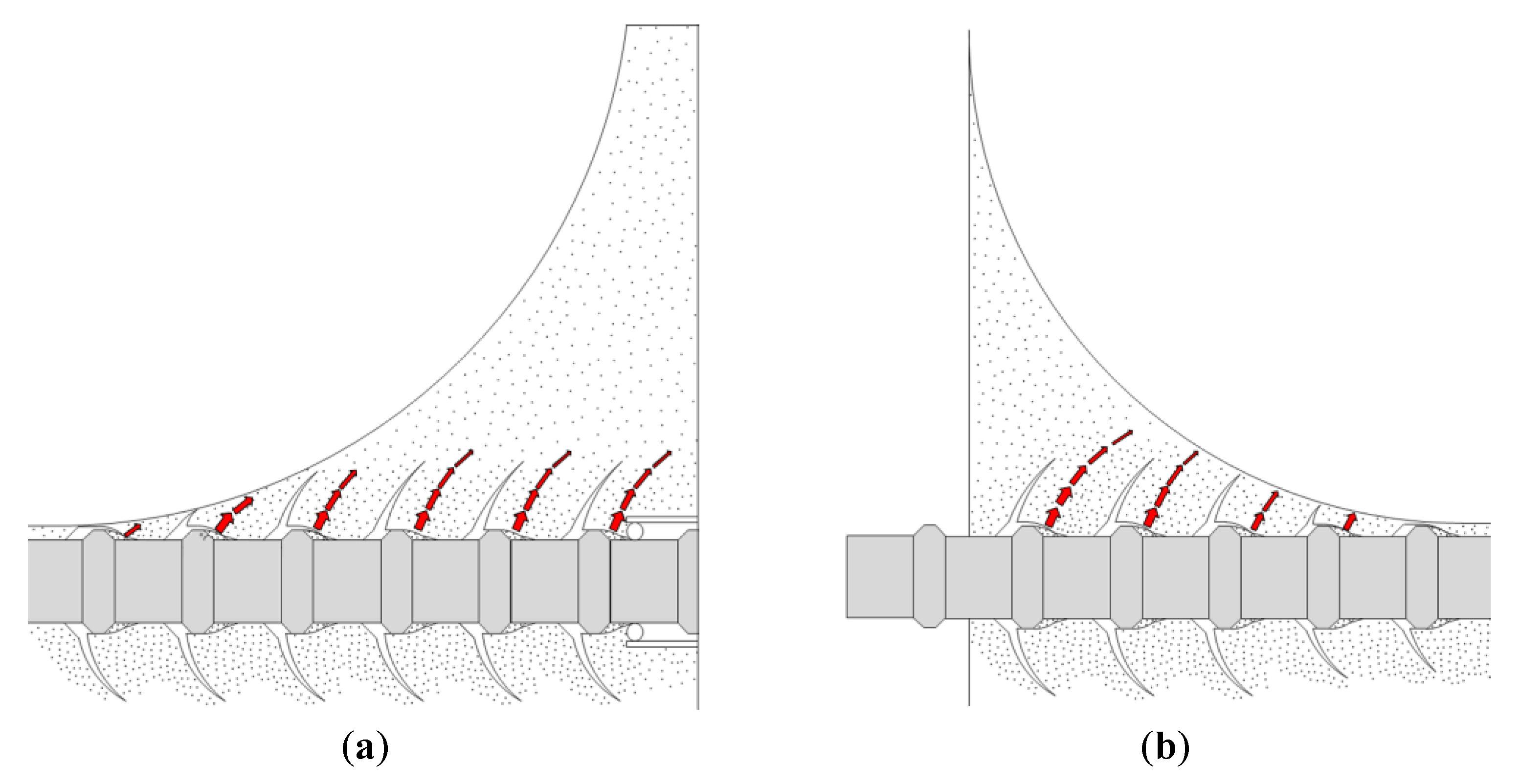
Figure 9.
The spalling of concrete at C-type region in GB-270-0-E.
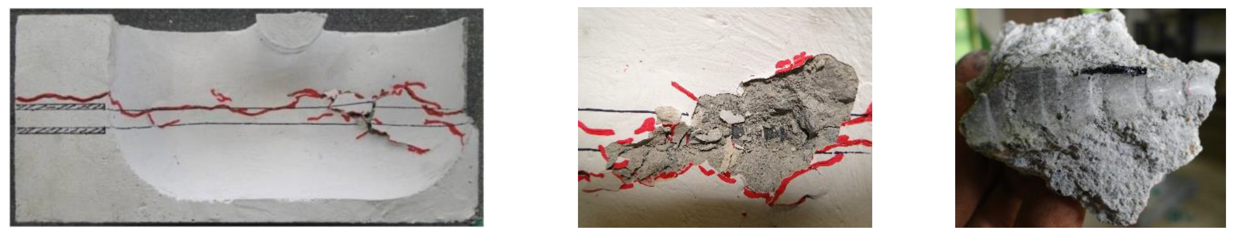
Figure 10.
Strain distribution of deformed steel bar; (a) GB-270-0-E vs. S-270-S-E; (b) GB-270-10-E vs. S-270-S-E; (c) GB-270-26-E vs. S-270-S-E.
Figure 10.
Strain distribution of deformed steel bar; (a) GB-270-0-E vs. S-270-S-E; (b) GB-270-10-E vs. S-270-S-E; (c) GB-270-26-E vs. S-270-S-E.
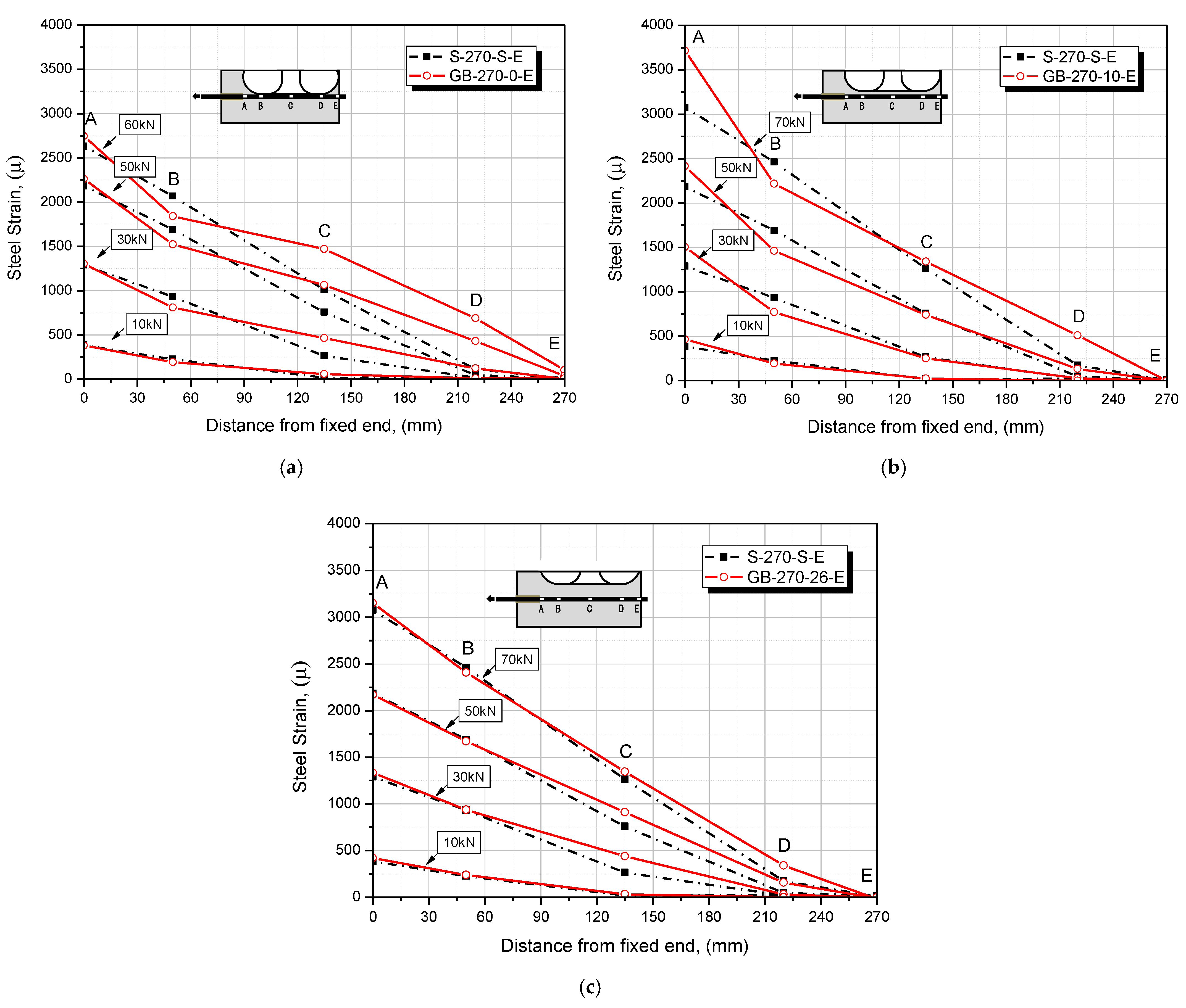
Figure 11.
Bond stress distribution: (a) GB-270-0-E vs. S-270-S-E; (b) GB-270-10-E vs. S-270-S-E; (c) GB-270-26-E vs. S-270-S-E.
Figure 11.
Bond stress distribution: (a) GB-270-0-E vs. S-270-S-E; (b) GB-270-10-E vs. S-270-S-E; (c) GB-270-26-E vs. S-270-S-E.

Table 1.
Details of test specimens.

| Specimen | [MPa] | Rebar Diameter [mm] | Height [mm] | Width [mm] | Length [mm] | Parameters | ||
|---|---|---|---|---|---|---|---|---|
| Embedded Length [mm] | Inner-Cover Thickness [mm] | Bond Region | ||||||
| S-270-S-E | 30.4 | 12.7 (D13) | 150 | 150 | 335 | 270 | - | - |
| GB-270-0-E | 0 | Entire | ||||||
| GB-270-10-E | 10 | |||||||
| GB-270-26-E | 26 | |||||||
| GB-50-0-A | 50 | 0 | A-Type (Transition Region 1) | |||||
| GB-50-10-A | 10 | |||||||
| GB-50-26-A | 26 | |||||||
| GB-50-0-B | 0 | B-Type (Insufficient Region) | ||||||
| GB-50-10-B | 10 | |||||||
| GB-50-26-B | 26 | |||||||
| GB-50-0-C | 0 | C-Type (Transition Region 2) | ||||||
| GB-50-10-C | 10 | |||||||
| GB-50-26-C | 26 | |||||||
Note: S: Solid Slab, GB: Donut-type voided slab.
Table 2.
Mix proportion of concrete.
| Design Strength [MPa] | W/C [%] | S/a [%] | Unit Weight [kg/m3] | ||||
|---|---|---|---|---|---|---|---|
| W | C | S | G | Admixture | |||
| 30 | 44.2 | 46.9 | 165 | 373 | 837 | 966 | 1.87 |
Note: W: Water, C: Cement, S: Sand, G: Gravel Solid Slab, W/C: Water to Cement ratio, S/a: Sand to Aggregate ratio.
Table 3.
Tensile strength of the deformed steel bar.
| Rebar Type | Nominal Strength [MPa] | Yield Strength [MPa] | Ultimate Strength [MPa] | Elongation [%] | Elastic Modulus [GPa] |
|---|---|---|---|---|---|
| D13 | 500 | 576 | 751.57 | 12.21 | 203 |
Table 4.
Test results of the short specimen.
| Specimen | Failure Mode | |||
|---|---|---|---|---|
| GB-50-0-A | 28.74 | 14.41 | 1.29 | Pullout |
| GB-50-10-A | 35.14 | 17.61 | 1.74 | Pullout |
| GB-50-26-A | 30.41 | 15.24 | 0.78 | Pullout |
| GB-50-0-B | 12.20 | 6.12 | 0.35 | Splitting |
| GB-50-10-B | 21.84 | 10.95 | 0.85 | Pullout |
| GB-50-26-B | 35.01 | 17.55 | 1.14 | Pullout |
| GB-50-0-C | 14.37 | 7.20 | 0.38 | Splitting |
| GB-50-10-C | 29.81 | 14.94 | 0.38 | Splitting |
| GB-50-26-C | 33.00 | 16.54 | 0.93 | Pullout |
Note: : the ultimate bond force, : bond stress, : maximum slip.
Table 5.
Test results of the entire type specimen.
| Specimen | Failure Mode | Location | |||
|---|---|---|---|---|---|
| S-270-S-E | 87.10 | 8.10 | 10.23 | Yielding | B |
| GB-270-0-E | 60.27 | 5.59 | 11.69 | Splitting | A |
| GB-270-10-E | 72.93 | 6.77 | 13.38 | Splitting | A |
| GB-270-26-E | 89.60 | 8.32 | 10.47 | Yielding | B |
Note: : the ultimate bond force, : bond stress, : maximum slip.
Table 6.
Test results vs. suggested method.
| Specimen | Test Result | Conventional Method | Suggested Method | |||
|---|---|---|---|---|---|---|
[kN] | [kN] | [kN] | [kN] | [kN] | [kN] | |
| GB-270-0-E | 60.27 | 26.85 | 20.23 | 45.61 | 52.25 | 61.68 |
| GB-270-10-E | 72.93 | 42.78 | 28.88 | 56.50 | 76.61 | 77.30 |
| GB-270-26-E | 89.60 | 60.04 | 43.27 | 66.04 | 114.51 | 110.47 |
Note: : The ultimate bond force.
Publisher’s Note: MDPI stays neutral with regard to jurisdictional claims in published maps and institutional affiliations. |
© 2022 by the authors. Licensee MDPI, Basel, Switzerland. This article is an open access article distributed under the terms and conditions of the Creative Commons Attribution (CC BY) license (https://creativecommons.org/licenses/by/4.0/).
Share and Cite
MDPI and ACS Style
Chung, J.-H.; Jung, H.-S.; Choi, H.-K. Bond Characteristics of a Deformed Steel Bar Embedded in Donut-Type Voided Slab. Appl. Sci. 2022, 12, 5666. https://doi.org/10.3390/app12115666
AMA Style
Chung J-H, Jung H-S, Choi H-K. Bond Characteristics of a Deformed Steel Bar Embedded in Donut-Type Voided Slab. Applied Sciences. 2022; 12(11):5666. https://doi.org/10.3390/app12115666
Chicago/Turabian StyleChung, Joo-Hong, Hyung-Suk Jung, and Hyun-Ki Choi. 2022. "Bond Characteristics of a Deformed Steel Bar Embedded in Donut-Type Voided Slab" Applied Sciences 12, no. 11: 5666. https://doi.org/10.3390/app12115666
Note that from the first issue of 2016, this journal uses article numbers instead of page numbers. See further details here.