


A Low-Latency Fair-Arbiter Architecture for Network-on-Chip Switches

1
College of Biomedical Engineering and Instrument Science, Zhejiang University, Hangzhou 310027, China
2
College of Cyberspace Security, Hangzhou Dianzi University, Hangzhou 310027, China
*
Author to whom correspondence should be addressed.
Appl. Sci. 2022, 12(23), 12458; https://doi.org/10.3390/app122312458
Submission received: 18 October 2022
/
Revised: 29 November 2022
/
Accepted: 2 December 2022
/
Published: 6 December 2022
(This article belongs to the Topic Electronic Communications, IOT and Big Data)
Abstract
:As semiconductor technology evolves, computing platforms attempt to integrate hundreds of processing cores and associated interconnects into a single chip. Network-on-chip (NoC) technology has been widely used for data exchange centers in recent years. As the core element of the NoC, the round-robin arbiter provides fair and fast arbitration, which is essential to ensure the high performance of each module on the chip. In this paper, we propose a low-latency fair switch arbiter (FSA) architecture based on the tree structure search algorithm. The FSA uses a feedback-based parallel priority update mechanism to complete the arbitration within the leaf nodes and a lock-based round-robin search algorithm to guarantee global fairness. To reduce latency, the FSA keeps the lock structure only at the leaf node so that the complexity of the critical path does not increase. Meanwhile, the FSA achieves a critical path with only delay by using four input nodes in parallel. The latency of the proposed circuit is on average 22.2% better than the existing fair structures and 8.1% better than the fastest arbiter, according to the synthesis results. The proposed architecture is well suited for high-speed network-on-chip switches and has better scalability for switches with large numbers of ports.
1. Introduction
As the feature size of chips is reduced to the nanometer level, more processing elements can be placed on a system-on-chip (SoC) [1]. In recent years, AMD-Xilinx has proposed a SoC named the adaptable computing acceleration platform (ACAP) [2], which is a device-global memory-mapped network-on-chip [3,4] that connects the components and fabric in an integrated fashion. As the NoC unifies communication between the processor system, FPGA fabric, memory subsystem and other hardened accelerator functions, it is widely used in many complex systems, such as multi-core processing chips and large systems-on-chip. As an important scheduling part in NoC, an arbiter is essential to provide fair and reasonable services for shared resources, especially in high-speed network-on-chip switches [5].
NoC switches generally consist of input ports, a schedule, a crossbar and output ports, as shown in Figure 1. The round-robin arbiter (RRA) as a schedule is widely used in the NoC switching system [6,7]. It aims to provide control signals to the crossbar switch fabric. The RRA is placed on each output port to ensure that each input port can potentially request connections to all output ports. When the crossbar receives the arbitration information from the RRA, it opens the corresponding channel from the ingress to the egress. Thus, a packet is transferred. Therefore, the arbiter must be fair to prevent port starvation. However, the traditional switch is prone to a throughput limit because of the head-of-line (HoL) blocking [8] phenomenon. There are many solutions to the HoL problem [9]. The two most commonly used methods are virtual output queuing (VOQ) [10] and virtual channels (VCs) [11,12]. Although VOQ and VC can deliver better performance, they are challenging to implement because both of them require a high clock frequency [13]. As the arbiter is located in the critical pipeline stage [14] of the switch systems, the critical path of the arbiter limits the performance of the system. Therefore, designers should focus on the low latency and fairness of the arbiter.
In this study, we propose a new fair and fast switch arbiter called FSA. In FSA, the grant signal is used for priority updates to ensure the fairness of the leaf node. Moreover, to avoid the wrong update of the priority in the upper level, we propose using the lock signal to modify the request passing to the upper level. Furthermore, low latency can be guaranteed by using the priority logic in parallel.
This paper is organized as follows: Section 2 lists some typical arbiters and analyzes their advantages and disadvantages. Section 3 describes the structure of the FSA and demonstrates its fairness and high performance. Section 4 provides arbitration observation experiment results for all arbiters. Finally, we conclude this paper in Section 5.
2. Related Works and Analyses
In high-speed switching systems, the performance of the arbiter is critical. In computer network packet switching, studies have been conducted on the iterative round-robin algorithm (iSLIP) [15] and dual round-robin matching (DRRM) algorithm [16]. Moreover, Gupta and McKeown proposed two new programmable priority encoders (PPE) [17,18]. PPE is complicated for a simple round-robin arbiter; additionally, it is the centralized rotating-priority-pointer design.
With the expansion of the network exchange scale, a centralized arbitration structure becomes complex, which is detrimental to the implementation. To obtain better scalability, the tree structure has been proposed. Chao et al. proposed the arbitration algorithm named the ping-pong arbiter (PPA) [19], which features an -level tree structure. PPA has good scalability and low latency, but its fairness cannot be satisfied under unbalanced traffic [20]. As shown in Figure 2, when the number of input requests is less than N, although the root node permanently grants evenly, leaf nodes and intermediate nodes will obtain unbalanced grants owing to unbalanced input. Consequently, this results in different grant probabilities between different requests.
Another arbiter design using the similar research algorithm of “ping-pong”, called the switch arbiter (SA), was proposed in [21]. It is constructed using the 4-input instead of the 2-input arbiter block. Theoretically, it can obtain a lower delay than PPA [22]. However, in some special cases, the priority updates step-by-step results in an unfair situation. As shown in Figure 3, the SA becomes unfair with non-uniformly distributed requests. For example, when both channels 1 and 3 have data packets entering, supposing that the initial priority is , channel 1 will be authorized first. Thereafter, the channel priority order will be , and channel 3 will be authorized at this time. Subsequently, the channel priority order becomes . At this time, channel 3 is still authorized, which means unfairness occurs.
In addition, Zheng and Yang provided two main designs in the form of a parallel round-robin arbiter (PRRA) and an improved PRRA (IPRRA) [23]. Based on their work, the PRRA and IPRRA provide round-robin fairness for input conditions, whereas the IPRRA is expected to reduce timing delay over the PRRA. PRRA and IPRRA consist of levels of the binary tree. The lowest level nodes of the binary tree are called leaf nodes, which are connected in series by a priority pointer. The highest node is called the root node, and the rest of the nodes are called intermediate nodes. Although PRRA and IPRRA can provide fair arbitration, it significantly increases path delay.
In order to reduce the critical path delay (CPD) [24] of the arbiter, a gate-level circuit was proposed named ping-lock arbiter (PLA) [25]. This is also an architecture based on the “ping-pong” search algorithm. It improves the PPA structure to provide lower latency. Meanwhile, in order to solve the unfairness caused by the “ping-pong” algorithm, a lock structure is proposed to ensure the fairness of the tree structure. This lock structure exists at every node, which will increase the PLA’s critical path delay and utilization.
3. Fair Switch Arbiter
The analysis of arbiters in related works showed that we should provide fair arbitration and reduce arbitration delay to maximize switching throughput and performance for NoCs.
As mentioned before, a decentralized arbitration structure can perform better in a large switching system. We proposed a novel arbiter based on the tree structure, which divides and distributes the arbitration task to separate nodes, providing high-performance arbitration with excellent scalability. Figure 4 shows the structure of a round-robin arbiter with 32 requests as an example. The leaf node is the lowest level of the arbiter, whose inputs and outputs are used as the interface of the whole arbiter. The outputs of other nodes (i.e., ) are connected to the node as an acknowledgment to grant the result of the internal node or the leaf node to update their priority orders.
3.1. Fair Round-Robin Arbiter Scheme
It is essential that an arbiter provides dynamic, fair arbitration. Consider an n-input packet switch; herein, each input submits a one-bit request signal to every output, which indicates whether its packet is destined for the output. Each output arbiter collects all request signals and computes binary grant outputs , among which one input is granted to transmit packets. Assuming that in the previous arbitration cycle (if there is no , ; if , ), and s are set as follows.
An arbiter guarantees fairness among masters by changing the priority of all the requests. Initially, all ports obtain arbitration according to a certain priority order; if any input obtains the grant signal, assumed to be , the priority vector is pointed to next to .
To search for the maximum j, we encoded different states, as shown in Table 1. Different states have different priorities to ensure the request that has the highest priority can be met. Each state performs as a fixed priority arbiter (FPA) and priority vector as the condition for jumping among states. Contrary to the SA, we used a loop state machine with feedback, which can provide fair arbitration. As shown in Figure 5b, after a request is granted in each arbitration cycle, the state jumps to ensure that the highest priority is passed to the next request and the priority of the granted request is adjusted to the lowest point.
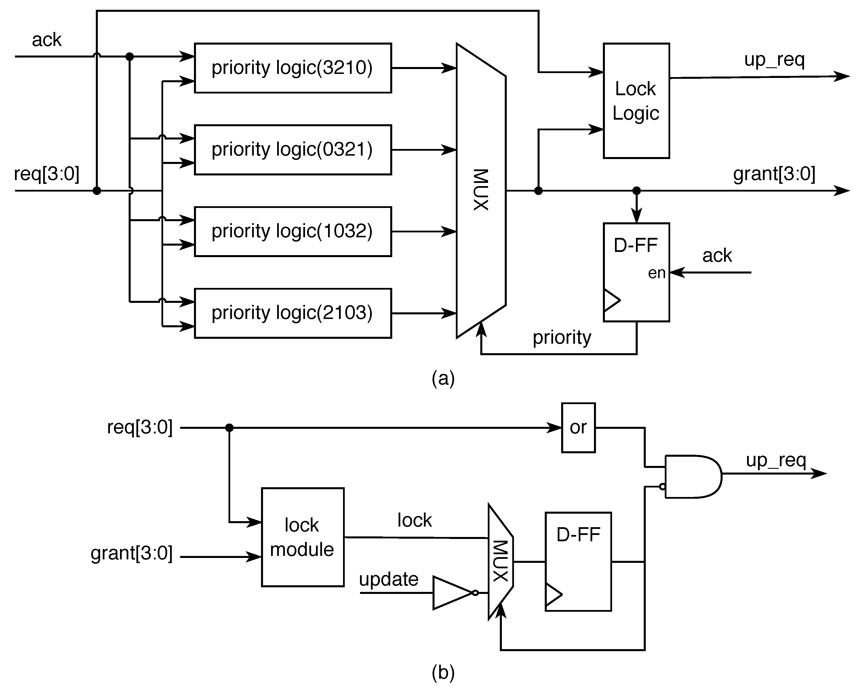
Figure 6 shows the structure of the leaf nodes of the arbiter. The proposed leaf node consists of a D flip-flop, four priority logic blocks, a MUX and a lock logic block. Four priority logic blocks correspond to the different states in Table 1. This will result in up to four different grant outcomes to choose from. The proposed architecture uses the previous grant feedback as the priority signal to instruct the loop state machine jumps. As shown in Table 1, each bit of the priority signal corresponds to a different output for a different priority case. Furthermore, we proposed a lock signal as an indication for the leaf node to complete a round of arbitration. When all requests from the leaf node are authorized, the lock signal will be set. As shown in Figure 6b, when the lock signal is set, the req signal passed to the upper layer is blocked. The definition of the lock logic is as follows.
For example, in the initialization phase, the result of the first priority logic block will be taken from the MUX. At this time, the state is 00, and the priority of four requests is . Supposing that only and want to be authorized, the token at this moment is four ( = 4’b0100, which indicates gets authorized) because the has higher priority. In the next arbitration cycle, the grant changes the priority signal to 4’b0100, and the state is jumped to 10. Thus, the arbiter processes request signals following the execution order of the third priority logic block in the current clock slot; indicates the highest priority. Considering the connection of the requests, because neither nor makes a request, has the highest priority and has the next highest priority. The signal is set when port 0 gets authorized; at this time the priority signal and up_req signal are not updated.
In summary, the grant signal in the FSA block is for both the output and the feedback that affect the priority transmission. Thus, the priority pointer can accurately point to the next request. As the value of is determined by the value of , unfairness caused by the port being selected twice in an arbitration cycle is prevented. Therefore, its fairness is guaranteed.
3.2. Round-Robin Arbiter Tree
The FSA features an -level tree structure. Considering that the number of ports is not a power of four, the level of the tree shown is as follows:
The tree structure is a decentralized framework that may disintegrate jobs into small chunks and distribute them to different nodes for completion. Each node in the tree structure is subdivided into leaf nodes, internal nodes and root nodes. Each node has the ability to act independently as an arbiter. The leaf node is in charge of replying to the node’s request while seeking authorization from the upper layer. The requests from the leaf nodes are grouped by the internal node, and the requests from the corresponding lower-level nodes are handled by the root node. The structure of the leaf node is shown in Figure 6, and the internal and root nodes are shown in Figure 7. If is odd, the root node uses the root2 node.
The FSA structure is shown in Figure 4; all nodes are connected using and signals. The leaf node receives a four-bit signal in each arbitration cycle, selects the authorization signal based on the priority signal and creates the signal to request authorization from the upper layer. The signal is forwarded to the root node after passing through a gathering of internal nodes. Thereafter, the root node acknowledges the request and transmits the information to the lower-level node through the signal.
According to the analysis in Section 2, the tree structure is unfair for nonuniformly distributed requests, as it utilizes a generic priority update mechanism. To address this unfairness, we suggested that every input of leaf nodes should be serviced once before the priority vector of the higher-level node is updated. Therefore, the arbitration of the internal node and root node should ensure that the priority is not updated until the lower-level node completes its arbitration.
Based on the new priority strategy, first, the node granted all requests. As shown in Equation (2), the signal indicates the completion of the node arbitration. We filtered out the upward request signal through the signal, which can indirectly ensure the update of the priority of the upper node. The proposed arbiter modified the signal as in Equation (3), to ensure that higher-level nodes could use the absolutely fair round-robin arbiter [26] as follows.
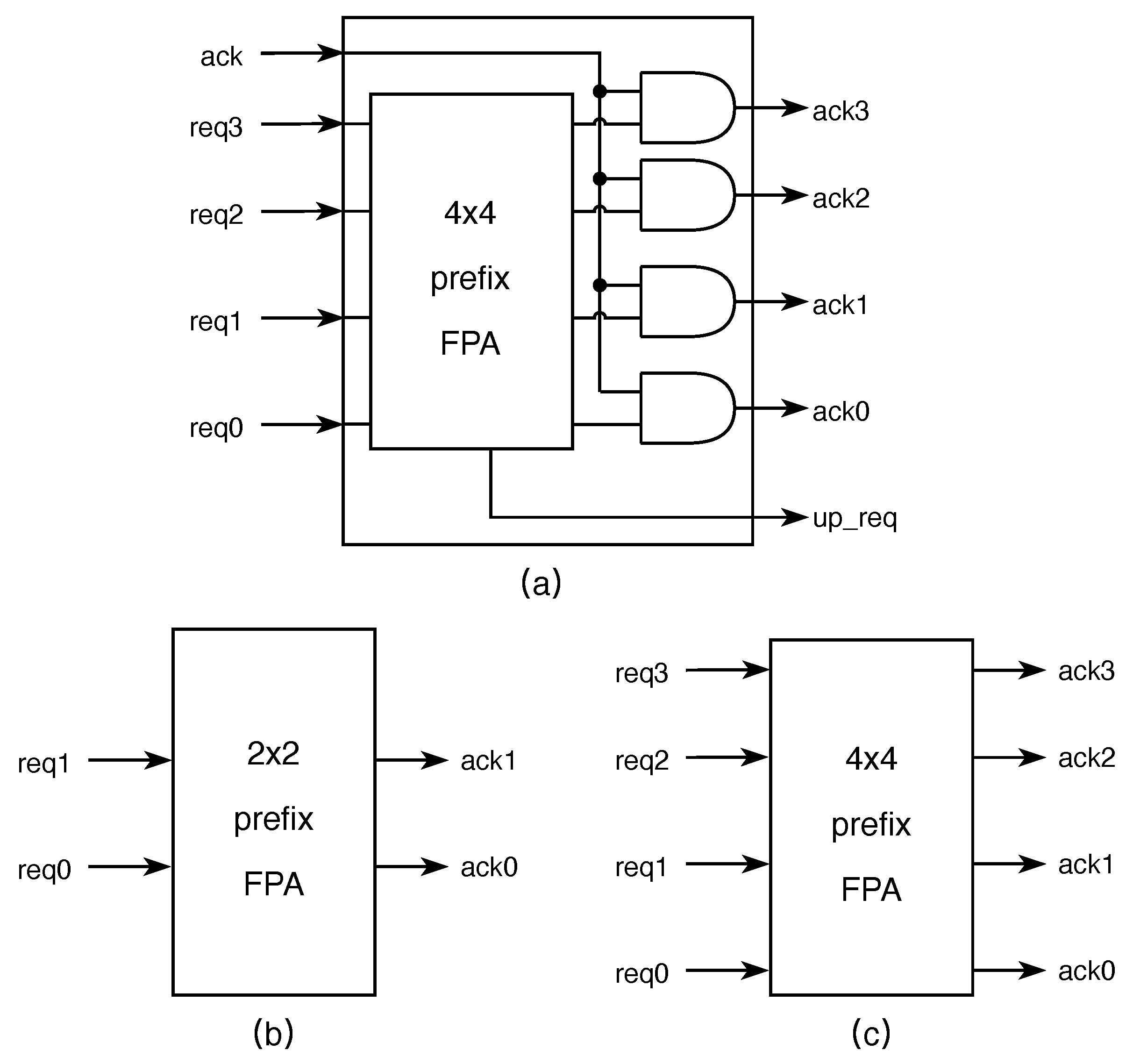
As shown in Figure 7, to achieve a shorter delay, we adopted the parallel prefix FPA [27] as the structure of the internal node and root node, which can obtain delay. By defining a prefix , we could express priority encoding as a prefix operation:
The resulting signals of the parallel prefix FPA in the internal node have to be ANDed with the ack signal, which is from the higher level, to indicate whether the result is valid or not. The updated signal in the root node indicates that the arbitration is complete.
4. Implementation and Experiment
To evaluate the arbiter’s performance, we selected some classical arbiters to analyze their critical paths and fairness [28]. Generally, the maximum delay path of the arbiter is from the time a leaf node launches an arbitration request to the upper layer to the time the upper layer responds to the authorization signal. We calculated the number of 2-input logic gates (3-input logic gates are counted as 1.5 unit gates) in the arbiters’ critical path. The result is shown in Table 2. The SA and the FSA use 4-input cells to ensure that the maximum delay increases with and others grow with .
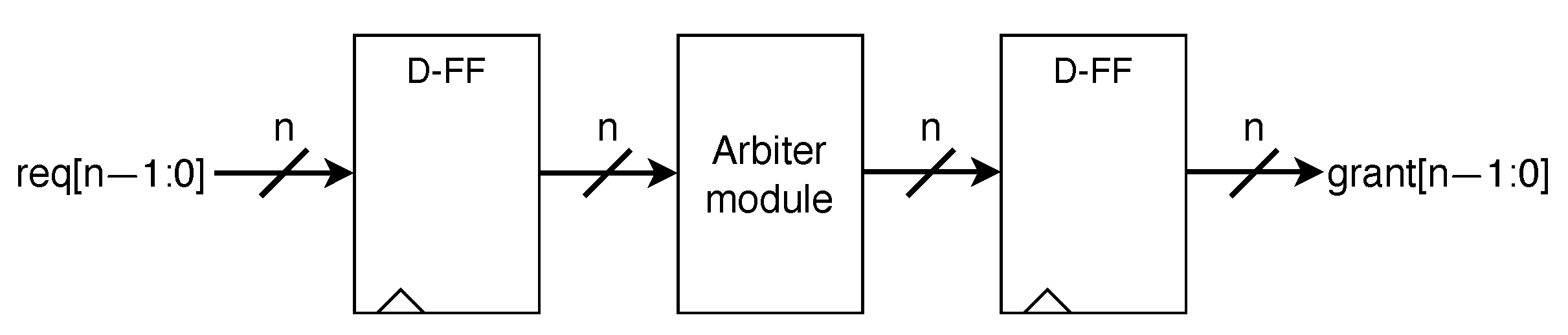
In order to assess their performances on ASICs, all arbiters were implemented in structural RTL Verilog code and synthesized in a 90 nm process [29]. Since the synthesis result depends on the target clock frequency, we employed the clock with different periods and selected the worst path as the latency of the arbiters. Considering that most arbiters use combinational logic as the input and output, the synthesis tool cannot correctly report the worst path. Therefore, we implemented the D flip-flop before and after the structure. The experimental module is shown in Figure 8.
The obtained delay is presented in Table 3 and Figure 9a. We list the most classic PPA structures as a basis in the table in order to make it easier to find the advantages of each structure. As shown in Figure 9a, the timing delays of SA and FSA grow with , and others grow with . Except for PRRA, the other results were generally in line with our expectations. The PRRA was optimized by the synthesizer using the 3-input logic gate, so its critical path becomes . On a small scale, the FSA has a slightly longer delay than SA; however, it has better latency on a large scale. Averagely, the FSA obtains the best latency. Compared to the PLA, the FSA only keeps the locking structure at the leaf nodes, and its complexity does not increase as the tree structure level increases. The FSA is faster than other architectures on a wide scale, with a timing improvement of 8.1% over SA and one of 22.2% over PLA, on average.
The achieved areas are presented in Table 4 and Figure 9b. As shown in Figure 9b, since the arbiters mentioned are decentralized structures, the area of each arbiter is grown linearly with N. Owing to the more complex structure of the FSA’s leaf nodes, the proposed arbiter did not achieve better outcomes in comparison to simple arbiters. The area reduction in ASIC implementation was obtained using the parallel prefix FPA structure, which simplified the structure of the upper node. Averagely, the PRRA has the smallest area owing to its simple structure. The FSA performed better than SA, with 12.2% area reduction on average.
Furthermore, we implemented the arbiters on Xilinx’s VC709 [30,31] development board to evaluate the performance of the arbiter on the FPGA. As shown in Table 5, at 250 MHz, all of the arbiters can be realized under the condition of , and the delay situation typically conforms to the trend under ASIC. However, only the FSA can achieve a scale of 128 with a 400 MHz clock, and the SA can only achieve a scale of 64. The FPGA results are reported in Table 6. The proposed arbiter uses 14% less LUT resources than PLA and uses 17% less flip-flop than SA.
5. Conclusions
In order to ensure that high-performance network-on-chip switches can provide efficient, reliable data exchange capabilities, we focused on improving the performance of the arbiter, mainly in terms of fairness and low latency. The architecture we proposed ensures that all input requests are treated fairly, which designs based on the “ping-pong” algorithm cannot do. The FSA has an critical path delay and is the fastest design, which is exactly what a high-performance switching system needs to be. The most critical feature of our design is that we implemented the search algorithm in layers. We implemented the parallel algorithm for achieving fairness at the leaf node and implemented a high-speed parallel search structure at the upper layer. This will ensure that the FSA will be more scalable in large switching systems. The proposed structure will perform better as the system-on-chip’s performance is improved and more nodes are added to it.
Author Contributions
Conceptualization, J.L., Q.X. and F.Y.; methodology, J.L., W.W. and Z.M.; software, J.L. and M.X.; validation, J.L., W.W. and Q.X.; formal analysis, J.L., W.W. and Q.X.; investigation, J.L. and M.X.; data curation, J.L.; writing—original draft preparation, J.L. and W.W.; writing—review and editing, J.L., W.W., Q.X., M.X., F.Y. and Z.M.; visualization, J.L.; supervision, Z.M.; project administration, Z.M. All authors have read and agreed to the published version of the manuscript.
Funding
This research received no external funding.
Institutional Review Board Statement
Not applicable.
Informed Consent Statement
Not applicable.
Data Availability Statement
The data presented in this study are available on request from the corresponding author.
Conflicts of Interest
The authors declare no conflict of interest.
References
- Chakravarthi, V.S. A Practical Approach to VLSI System on Chip (SoC) Design; Springer: Berlin/Heidelberg, Germany, 2020. [Google Scholar]
- Swarbrick, I.; Gaitonde, D.; Ahmad, S.; Gaide, B.; Arbel, Y. Network-on-Chip Programmable Platform in VersalTM ACAP Architecture. In Proceedings of the 2019 ACM/SIGDA International Symposium on Field-Programmable Gate Arrays, Seaside, CA, USA, 24–26 February 2019; Association for Computing Machinery: New York, NY, USA, 2019; pp. 212–221. [Google Scholar]
- Dimitrakopoulos, G.; Psarras, A.; Seitanidis, I. Microarchitecture of Network-on-Chip Routers; Springer: New York, NY, USA, 2015. [Google Scholar]
- Soundari, D.; Ganesh, M.S.; Raman, I.; Karthick, R. Enhancing network-on-chip performance by 32-bit RISC processor based on power and area efficiency. Mater. Today Proc. 2021, 45, 2713–2720. [Google Scholar] [CrossRef]
- Das, T.S.; Ghosal, P.; Chatterjee, N. Virtual circuit switch based orderly delivery of packets in adaptive NoC routing. In Proceedings of the 12th International Workshop on Network on Chip Architectures, Columbus, OH, USA, 13 October 2019; pp. 1–6. [Google Scholar]
- Aweya, J. Switch/Router Architectures: Shared-Bus and Shared-Memory Based Systems; IEEE Series on Mobile & digital Communication; Wiley: Hoboken, NJ, USA, 2018. [Google Scholar]
- Dananjayan, P.; Vanga, K.R. Low Latency NoC Switch using Modified Distributed Round Robin Arbiter. J. Eng. Sci. Technol. Rev. 2021, 14, 76–84. [Google Scholar]
- Karol, M.; Hluchyj, M.; Morgan, S. Input Versus Output Queueing on a Space-Division Packet Switch. IEEE Trans. Commun. 1987, 35, 1347–1356. [Google Scholar] [CrossRef] [Green Version]
- Mohtavipour, S.M.; Mollajafari, M.; Naseri, A. A novel packet exchanging strategy for preventing HoL-blocking in fat-trees. Clust. Comput. 2020, 23, 461–482. [Google Scholar] [CrossRef]
- Papaphilippou, P.; Sano, K.; Adhi, B.A.; Luk, W. Efficient Queue-Balancing Switch for FPGAs. In Proceedings of the 2021 International Conference on Field-Programmable Technology (ICFPT), Auckland, New Zealand, 6–10 December 2021; pp. 1–5. [Google Scholar]
- Gangwar, A.; Sreedharan, R.; Prasad, A.; Agarwal, N.K.; Gade, S.H. Topology Agnostic Virtual Channel Assignment and Protocol Level Deadlock Avoidance in a Network-on-Chip. In Proceedings of the 2021 58th ACM/IEEE Design Automation Conference (DAC), San Francisco, CA, USA, 5–9 December 2021; pp. 61–66. [Google Scholar]
- Guo, Y.; Zheng, H.; Wang, J.; Xiao, S.; Li, G.; Yu, Z. A Low-Cost and High-Throughput Virtual-Channel Router with Arbitration Optimization. In Proceedings of the 2019 IEEE International Conference on Integrated Circuits, Technologies and Applications (ICTA), Chengdu, China, 13–15 November 2019; pp. 75–76. [Google Scholar]
- Avani, P.; Agrawal, S. Efficient Dynamic Virtual Channel Architecture for NoC Systems. In Proceedings of the 2018 International Conference on Advances in Computing, Communications and Informatics (ICACCI), Bangalore, India, 19–22 September 2018; pp. 2502–2507. [Google Scholar]
- Papaphilippou, P.; Meng, J.; Gebara, N.; Luk, W. Hipernetch: High-Performance FPGA Network Switch. ACM Trans. Reconfigurable Technol. Syst. (TRETS) 2021, 15, 1–31. [Google Scholar] [CrossRef]
- Mei, L.C.; Qiao, L.F.; Chen, Q.H.; Yang, L.; Yang, J. A Packet Dispatching Scheme with Load Balancing Based on iSLIP for Satellite Onboard CIOQ Switches. In Lecture Notes in Electrical Engineering, Proceedings of the International Conference in Communications, Signal Processing, and Systems; Springer: Berlin/Heidelberg, Germany, 2016; pp. 77–85. [Google Scholar]
- Han, K.E.; Song, J.; Kim, D.U.; Youn, J.; Park, C.; Kim, K. Grant-Aware Scheduling Algorithm for VOQ-Based Input-Buffered Packet Switches. ETRI J. 2018, 40, 337–346. [Google Scholar] [CrossRef]
- Gupta, P.; McKeown, N. Designing and implementing a fast crossbar scheduler. IEEE Micro 1999, 19, 20–28. [Google Scholar] [CrossRef]
- Mirhosseini, A.; Sadrosadati, M.; Aghamohammadi, F.; Modarressi, M.; Sarbazi-Azad, H. BARAN: Bimodal Adaptive Reconfigurable-Allocator Network-on-Chip. ACM Trans. Parallel Comput. 2019, 5, 1–29. [Google Scholar] [CrossRef]
- Chao, H.; Lam, C.; Guo, X. A fast arbitration scheme for terabit packet switches. In Proceedings of the Seamless Interconnection for Universal Services, Global Telecommunications Conference, GLOBECOM’99, (Cat. No.99CH37042), Rio de Janeiro, Brazil, 5–9 December 1999; Volume 2, pp. 1236–1243. [Google Scholar]
- Khan, A.A.; Mir, R.N.; Din, N.U. Adaptive hybrid arbiter design for real-time traffic-aware scheduling. Circuit World 2021, 48, 185–203. [Google Scholar] [CrossRef]
- Shin, E.S.; Mooney, V.J.; Riley, G.F. Round-Robin Arbiter Design and Generation. In Proceedings of the 15th International Symposium on System Synthesis, Kyoto, Japan, 2–4 October 2002; Association for Computing Machinery: New York, NY, USA, 2002; pp. 243–248. [Google Scholar]
- Monfared, J.R.; Mousavi, A. Design and simulation of nano-arbiters using quantum-dot cellular automata. Microprocess Microsyst. 2020, 72, 102926. [Google Scholar] [CrossRef]
- Zheng, S.Q.; Yang, M. Algorithm-Hardware Codesign of Fast Parallel Round-Robin Arbiters. IEEE Trans. Parallel Distrib. Syst. 2007, 18, 84–95. [Google Scholar] [CrossRef]
- Ahmed, A.B.; Fujiki, D.; Matsutani, H.; Koibuchi, M.; Amano, H. AxNoC: Low-power Approximate Network-on-Chips using Critical-Path Isolation. In Proceedings of the 2018 Twelfth IEEE/ACM International Symposium on Networks-on-Chip (NOCS), Torino, Italy, 4–5 October 2018; pp. 1–8. [Google Scholar]
- Monemi, A.; Ooi, C.Y.; Palesi, M.; Marsono, M.N. Ping-lock round robin arbiter. Microelectron. J. 2017, 63, 81–93. [Google Scholar] [CrossRef]
- Turko, T.; Uhring, W.; Dadouche, F.; Fesquet, L. An Asynchronous Fixed Priority Arbiter for High througput Time Correlated Single Photon Counting Systems. In Proceedings of the 2018 25th IEEE International Conference on Electronics, Circuits and Systems (ICECS), Bordeaux, France, 9–12 December 2018; pp. 765–768. [Google Scholar]
- Thakur, G.; Sohal, H.; Jain, S. Design and Analysis of High-Speed Parallel Prefix Adder for Digital Circuit Design Applications. In Proceedings of the 2020 International Conference on Computational Performance Evaluation (ComPE), Shillong, India, 2–4 July 2020; pp. 095–100. [Google Scholar]
- van Pinxten, J.; Geilen, M.; Hendriks, M.; Basten, T. Parametric Critical Path Analysis for Event Networks With Minimal and Maximal Time Lags. IEEE Trans.-Comput.-Aided Des. Integr. Circuits Syst. 2018, 37, 2697–2708. [Google Scholar] [CrossRef]
- Gayathri, S.; Taranath, T.C. RTL synthesis of case study using design compiler. In Proceedings of the 2017 International Conference on Electrical, Electronics, Communication, Computer, and Optimization Techniques (ICEECCOT), Mysuru, India, 15–16 December 2017; pp. 1–7. [Google Scholar]
- Virtex-7 XT VC709 Connectivity Kit. Available online: https://docs.xilinx.com/v/u/en-US/ug966-v7-xt-connectivity-getting-started (accessed on 1 December 2022).
- Taraate, V. ASIC and FPGA Synthesis. In Advanced HDL Synthesis and SOC Prototyping; Springer: Berlin/Heidelberg, Germany, 2019; pp. 159–172. [Google Scholar]
Figure 1.
Network-on-chip switch architecture.

Figure 2.
Unfair example of PPA.

Figure 3.
Unfair example of an SA cell.

Figure 4.
Round-robin 32-node binary tree structure.

Figure 5.
State transition diagram: (a) SA cell; (b) FSA cell.

Figure 6.
Block diagram of the FSA’s leaf node. (a) Leaf node. (b) Lock logic module.

Figure 7.
Internal node and root node structure. (a) Internal node. (b) Root2 node. (c) Root4 node.

Figure 8.
Experimentalmodule.

Figure 9.
Comparison of all arbiters. (a) Timing. (b) Area.


Table 1.
State code description.
| Priority | State | Priority Order |
|---|---|---|
| 4’b0001 | 00 | |
| 4’b0010 | 01 | |
| 4’b0100 | 10 | |
| 4’b1000 | 11 |
Table 2.
Complexity analysis of the arbiters.
| Arbiter | Critical Path | Arbiter Logic Gate (N = 256) | Fariness |
|---|---|---|---|
| PPA | 16 | unfair | |
| SA | 15 | unfair | |
| PRRA | 35 | fair | |
| IPRRA | 20 | fair | |
| PLA | 15 | fair | |
| FSA | 14 | fair |
Table 3.
Timing results of the arbiters (ns).
| Port Number | PPA [19] (Unfair) | SA [21] (Unfair) | PRRA [23] | IPRRA [23] | PLA [25] | FSA |
|---|---|---|---|---|---|---|
| N = 4 | 0.15 | 0.14 | 0.20 | 0.20 | 0.19 | 0.14 |
| N = 8 | 0.21 | 0.20 | 0.26 | 0.25 | 0.24 | 0.21 |
| N = 16 | 0.27 | 0.23 | 0.34 | 0.30 | 0.28 | 0.23 |
| N = 32 | 0.34 | 0.29 | 0.40 | 0.36 | 0.33 | 0.26 |
| N = 64 | 0.42 | 0.35 | 0.46 | 0.40 | 0.37 | 0.28 |
| N = 128 | 0.50 | 0.37 | 0.54 | 0.48 | 0.43 | 0.33 |
| N = 256 | 0.61 | 0.41 | 0.58 | 0.53 | 0.50 | 0.37 |
| N = 512 | 0.68 | 0.45 | 0.67 | 0.61 | 0.54 | 0.42 |
| Average | 100% | 76% | 108% | 98% | 90% | 70% |
Table 4.
Area results of the arbiters (um).
| Port Number | PPA [19] Unfair | SA [21] Unfair | PRRA [23] | IPRRA [23] | PLA [25] | FSA |
|---|---|---|---|---|---|---|
| N = 4 | 342 | 402 | 341 | 366 | 318 | 404 |
| N = 8 | 827 | 958 | 785 | 783 | 865 | 1076 |
| N = 16 | 1694 | 1930 | 1534 | 1540 | 1903 | 2015 |
| N = 32 | 3288 | 3844 | 2582 | 2864 | 3765 | 3713 |
| N = 64 | 6773 | 7722 | 5346 | 5977 | 7331 | 6936 |
| N = 128 | 13,052 | 15,559 | 10,255 | 10,793 | 14,135 | 13,761 |
| N = 256 | 25,113 | 30,826 | 21,121 | 21,482 | 28,231 | 26,704 |
| N = 512 | 50,319 | 60,844 | 40,891 | 41,940 | 54,470 | 52,608 |
| Average | 100% | 120% | 81% | 85% | 109% | 105% |
Table 5.
Performance and scale of FPGA.
| Frequency | PPA [19] | SA [21] | PRRA [23] | IPRRA [23] | PLA [25] | FSA |
|---|---|---|---|---|---|---|
| 250 MHz | (3.6 ns) | (3.5 ns) | (3.9 ns) | (3.7 ns) | (3.7 ns) | (3.4 ns) |
| 300 MHz | (3.3 ns) | (3.2 ns) | (3.3 ns) | (3.1 ns) | (3.3 ns) | (3.1 ns) |
| 400 MHz | (2.3 ns) | (2.4 ns) | (2.3 ns) | (2.4 ns) | (2.4 ns) | (2.4 ns) |
Table 6.
FPGA utilization (LUT/FF).
| Port Number | PPA [19] | SA [21] | PRRA [23] | IPRRA [23] | PLA [25] | FSA |
|---|---|---|---|---|---|---|
| N = 4 | 7/11 | 8/12 | 7/12 | 7/12 | 10/11 | 6/11 |
| N = 8 | 21/23 | 22/28 | 18/24 | 20/24 | 25/23 | 27/24 |
| N = 16 | 49/47 | 48/56 | 48/48 | 48/48 | 57/47 | 65/48 |
| N = 32 | 104/95 | 106/116 | 96/96 | 93/96 | 127/95 | 122/96 |
| N = 64 | 215/191 | 204/232 | 199/192 | 201/192 | 257/191 | 231/192 |
| N = 128 | 432/384 | 449/468 | 393/384 | 389/384 | 532/384 | 447/384 |
| N = 256 | 883/767 | 836/936 | 859/768 | 839/769 | 1102/767 | 904/768 |
| Avg(LUT) | 100% | 97% | 94% | 93% | 123% | 105% |
| Avg(FF) | 100% | 122% | 100% | 100% | 100% | 100% |
Publisher’s Note: MDPI stays neutral with regard to jurisdictional claims in published maps and institutional affiliations. |
© 2022 by the authors. Licensee MDPI, Basel, Switzerland. This article is an open access article distributed under the terms and conditions of the Creative Commons Attribution (CC BY) license (https://creativecommons.org/licenses/by/4.0/).
Share and Cite
MDPI and ACS Style
Luo, J.; Wu, W.; Xing, Q.; Xue, M.; Yu, F.; Ma, Z. A Low-Latency Fair-Arbiter Architecture for Network-on-Chip Switches. Appl. Sci. 2022, 12, 12458. https://doi.org/10.3390/app122312458
AMA Style
Luo J, Wu W, Xing Q, Xue M, Yu F, Ma Z. A Low-Latency Fair-Arbiter Architecture for Network-on-Chip Switches. Applied Sciences. 2022; 12(23):12458. https://doi.org/10.3390/app122312458
Chicago/Turabian StyleLuo, Jifeng, Wenqi Wu, Qianjian Xing, Meiting Xue, Feng Yu, and Zhenguo Ma. 2022. "A Low-Latency Fair-Arbiter Architecture for Network-on-Chip Switches" Applied Sciences 12, no. 23: 12458. https://doi.org/10.3390/app122312458
Note that from the first issue of 2016, this journal uses article numbers instead of page numbers. See further details here.