
Vibration Reduction in Ballasted Track Using Ballast Mat: Numerical and Experimental Evaluation by Wheelset Drop Test


1
School of Civil Engineering, Beijing Jiaotong University, No. 3, Shangyuan Village, Haidian District, Beijing 100044, China
2
Institute of Railway Research, University of Huddersfield, Huddersfield HD1 3DH, UK
3
IDMEC, Instituto Superior Técnico, Universidade de Lisboa, 1049-001 Lisboa, Portugal
4
ISEL, Intituto Politecnico de Lisboa, 1959-007 Lisboa, Portugal
*
Author to whom correspondence should be addressed.
Appl. Sci. 2022, 12(4), 1844; https://doi.org/10.3390/app12041844
Submission received: 10 January 2022
/
Revised: 5 February 2022
/
Accepted: 7 February 2022
/
Published: 10 February 2022
(This article belongs to the Special Issue Vibration Problems in Engineering Science)
Abstract
:Ballast mats are considered as an effective solution for reducing vehicle-induced vibrations. However, the research on the vibration characteristics of each part of the ballasted track with a ballast mat is limited. In this study, the ballast mat vibration reduction effects are evaluated by numerical and experimental analysis using wheelset drop tests. A three-dimensional model consisting of a wheel, track and the contact between them is built using a rigid–flexible coupling method. The accuracy of the numerical model is verified by comparison with the finite element model in terms of the track receptance and phase angle. Comparisons show that the proposed model is in good agreement with the finite element model, which allows validating the flexible-body model. Moreover, the track dynamic performance in the presence and absence of the ballast mat is studied with the wheelset drop tests in both time and frequency domains. The results from the wheelset drop excitation tests show that the use of the ballast mat decreases the mid- and high-frequency track vibration by 13–17 dB but increases the low-frequency track vibration by 5–15 dB.
1. Introduction
In high-speed and urban rail projects, vibration-reduction measures must be taken into account for areas that are highly sensitive to vibrations such as residential areas and precision instrument laboratories. To this end, different types of resilient tracks [1,2] and elastomer layers [3,4] have been widely used. At the same time, vibration reduction measures can also be taken in the building. Ersin Aydin [5] researched the application of additional dampers which will absorb part of the energy supplied to the building to reduce vibration. In addition to the transmission to the surrounding environment, the reduction of vehicle-track vibrations also has a strong influence on the maintenance of the tracks and on their life cycle costs, being to the subject several research works in the past years [6,7,8,9,10,11,12,13,14].
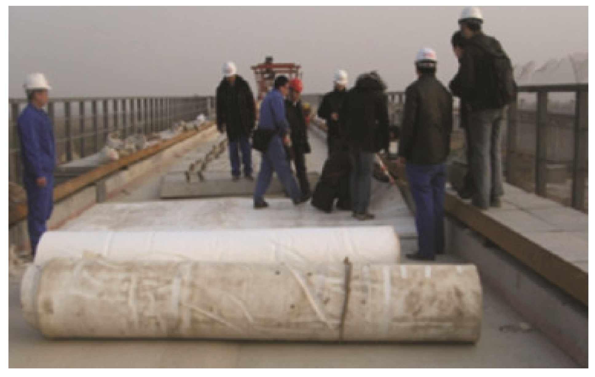
Because of the high cost of and technical issues associated with the new ballastless tracks, the traditional ballasted railway tracks are still deployed extensively throughout the world today. For ballasted tracks, ballast mats have been considered as an effective solution to reduce train-induced vibrations [15]. Figure 1 shows the cross-section of a ballasted track with a ballast mat, and Figure 2 shows the installation of a polyurethane ballast mat in China.
Diego [16] proposed a new material which was validated to produce anti-vibration mats for railway applications, and the vibration isolation effect has been analysed through a finite element model. Auersch [17] has compared the track deformation and wave propagation in the soil foundation with the unisolated and isolated ballast tracks through a frequency domain model. This theoretical research mainly focused on the vibration transmission and vibration reduction of ballast mats either in the time or in the frequency domain, as well as on the dynamic behaviours of vibrations with frequencies lower than 200 Hz. However, only few studies have focused on the dynamic characteristics of track components after the installation of ballast mats and especially on the response of the track vibration in the mid- and high-frequency ranges up to several thousand hertz. Track vibration control is crucial because tracks deteriorate with increasing vibration levels, changes in track geometry and the fatigue failure of components [18]. Furthermore, tracks undergo permanent deformation and degradation, and the breakage of ballast particles is highly influenced by the external loading frequency [19,20].
It is necessary to evaluate the vibration-reduction efficiency when the rail lines are close to sensitive areas. Yokoyama [21] has investigated the vibration isolation efficiency using a vehicle–track coupled model to predict the force transmitted through the ballast mat and then use it as the excitation to predict the building vibration nearby. However, sometimes when the line is not in operation or no experimental train is permitted to run through, it will be impossible to measure the vibration-reduction efficiency until the line is under operation. By then, it is usually difficult and costly to implement additional vibration reduction measures when it is observed that the vibration mitigation is insufficient. Under such circumstances, the wheelset drop test is often used to evaluate the dynamic characteristics of track structures. It has been observed that the structural dynamic response of the track in a wheelset drop test is equivalent to that under train operations [22]. So, the wheelset drop tests can produce reliable prediction on the vibration reduction efficiency. In a typical wheelset drop test, the wheelset is first lifted to some height (usually 20 or 25 mm) above the rail surface and then dropped. The impact force has enough energy to excite vibration in all the frequency ranges of interest. Then, the vibrations of each track component can be measured and used to analyse the vibration transfer function and vibration reduction.
In this work, the dynamics of ballasted tracks with and without the ballast mat are examined by the wheelset drop test using numerical analysis and experimental results. In Section 2, a three-dimensional coupled wheel–track model is established to simulate the wheelset drop process. The wheel is assumed to be rigid and can move in all directions. The track is modelled as a continuous Timoshenko beam laid on a two-layer spring-damper system that represents the sleeper and ballast. The track model is suitable for analysing track dynamics with frequencies up to 3000 Hz due to the beam assumption. The contact between the wheel and track is simulated based on the Hertz contact theory. The proposed track model is verified by comparing it with the finite element model. In Section 3, the ballasted tracks with and without the ballast mat are studied, and the vibrations of the rail, sleeper, and ballast are analysed in both the time and frequency domains. The insertion loss for each component is also analysed. Field tests are performed and the test results are compared with the numerical results. The agreement of both sets of results proves the validity of the numerical models proposed in this paper.
2. Wheel–Track Coupling Model
In previous studies, multibody dynamics analysis is often appropriate for studying systems with large rigid-body motions, whereas finite element analysis is more precise for studying system deformations subject to external forces and moments. Presently, the co-simulation of rigid-body dynamics and flexible-body dynamics has become the most suitable solution to study the vibration characteristics of a certain body in a large mechanical system. During this co-simulation process, the displacement vector of the flexible body is represented by the sum of the rigid-body displacement vector and body deformation vector [23,24]. Because rigid-body displacement can be acquired based on multibody dynamics, the representation of body flexibility in rigid multibody dynamics becomes the most important issue to ensure a successful simulation that incorporates flexible-body dynamics.
2.1. Flexible-Body Modelling Theory
To properly simulate flexible multibody dynamics, the primary issue is to reproduce the finite element model in the multibody dynamic model. This procedure is usually achieved through model reduction on the degrees of freedom (DOFs) of finite element model. Various reduction techniques can be applied to the finite element model, such as the Guyan method, dynamic condensation method, and component mode synthesis method [25,26,27,28,29]. According to the Guyan method, the undamped system vibration equation takes the following form:
where M and K are the n × n system mass matrix and stiffness matrix, respectively; a is the n × 1 system displacement vector; and F is the n × 1 load vector. Dividing the displacement vector a into blocks of am and as gives:
where am is the m × 1 displacement vector of the master DOFs and as is the (n–m) × 1 displacement vector of the slave DOFs. Assume am and as have the following relation:
where T is the m × m transforming matrix. The system displacement vector can be written in block form as follows:
where T* is the n × m transforming matrix. Equation (1) can be rewritten in block matrices as:
By pre-multiplying Equation (1) with (T*)T and eliminating as with Equation (4), Equation (1) can be written as:
where
In Equation (6), M* and K* are both m × m matrices. Thus, the rank of the system DOFs decreases from n to m.
In the static condensation process, the equivalent inertia items are omitted. Taking the system internal force Fs as zero, Equation (6) is converted to:
Solving Equation (8) for as gives:
where
The reduced mass matrix M* and stiffness matrix K* can be obtained by substituting Equation (9) into Equation (7):
From the above equations, it can be seen that the Guyan method is based on Equation (9). The error of this method can be obtained by solving Equation (5):
Differentiating Equation (12) twice with respect to time and comparing it with Equation (9), it is found that the method has exact solutions whenever:
2.2. Numerical Model
To study the dynamic performance of the ballast mat, a three-dimensional coupled wheel–rail model is implemented. The model can be divided into three parts, the wheel submodel, the rail submodel and the under-rail track component submodel, which contains the fasteners, the sleepers, the ballast and, when applicable, the ballast mat. The schematic diagram of the coupled model is shown in Figure 3.
2.2.1. Wheel Submodel
The wheel is modelled as a rigid body that has six DOFs. The mass of the wheel is 1200 kg, and it is dropped from a height of 25 mm over the rail surface.
The equation of the wheel motion is as follows:
where M, K denote the mass and stiffness of the wheel, respectively. Δw is the wheel displacement vector. The subscript w corresponds to the wheel. F denotes the load vector and includes two parts. One is the global gravity force FG, which is calculated by mass of the wheel times acceleration of gravity. The other is the contact force Fcontact between the wheel and rail, which is calculated based on the Hertz contact theory as follows:
where Δd denotes the relative displacement between the wheel and the rail at the contact point. R denotes the contact radius and is identical to the wheel radius in this case. E denotes the elastic modulus and is calculated as follows:
where Ew and Er denote the Young; s modulus of the wheel and rail; pw and pr denote the Poisson’s ratio of wheel and rail, respectively.
2.2.2. Rail Submodel
The equation of the ballasted track motion is as follows:
where M, C and K denote the mass, damping and stiffness matrices of the track, respectively. F denotes the load vectors. δ is the displacement vectors of each track components. The subscripts r, s and b correspond to the rail, sleeper and ballast each.
For the ballasted railway track structure, considering the modelling accuracy and efficiency, the rail is simulated as a continuous Timoshenko beam with dynamic response frequencies up to 3000 Hz. In this study, the cut-off frequency is chosen as 3000 Hz because if the vibration propagation waves in the rail is higher, the rail profile’s local deformation becomes the major vibration mode, which will be inaccurately simulated by the beam hypothesis [30]. In other words, only when the frequency range is not higher than 3000 Hz, the rail profile local deformation can be ignored, and thus the model established based on the beam assumption can be used. In the first modelling step of the finite element analysis, the rail is simulated using the standard 60 kg/m rail section and the mesh size is 0.3 m per element. To eliminate the boundary effect on the numerical calculation accuracy, the rail is considered to be 60 m long and fixed at both ends, and the wheel is dropped at the centre of the rail. When the rail model is defined, the related information such as the geometry, material properties, mass, damping and stiffness matrices are extracted through a substructure analysis. By performing a modal analysis, the mode shapes and vectors are obtained and later loaded to serve as the foundation for the dynamic analysis based on the modal superposition method. In the substructure analysis, the Guyan method is adopted, and all the nodes are employed as the master nodes. In the modal analysis, the block Lancoz method is adopted to obtain the modal solution, and a total of 800 eigen-frequencies (up to 3000 Hz) are included in the rail model.
2.2.3. Under-Rail Track Component Submodel
The sleeper and ballast are simulated by the mass–spring–damper system. The shear stiffness between different ballast particles is also considered in the model. The ballast mat, when used, is directly considered as a spring–damper element inserted between the ballast and the subgrade. The system parameters are listed in Table 1.
2.2.4. Numerical Model Building
After building all submodels, these are connected by spring–damper systems, and a contact element based on the Hertz contact theory is generated between the wheel and rail to simulate the wheel drop impact. Because the wheelset drop test can be regarded as an impact process, no excitation or rail roughness is considered in the model. By coupling the Equation (14) and Equation (17) together while adopting the superscript M and F, which denote the dynamic equations based on the MBS theory and FEM theory, respectively, the system equations can be obtained as follows:
In the above equation, the subscript T denotes for the track structure, and the other notations are as defined earlier. The wheel–rail impact force acts as an internal force on the system and is exerted on both the wheel and the track when the contact is closed. The motions of the wheel and track structure are coupled and updated in each time step.
The entire model established in Multibody System (MBS) software is shown in Figure 4. In the model, the blue cubes represent the rail elements, which are modelled with Timoshenko beam formulation. The displacement at arbitrary location between two adjacent nodes is obtained through Hermite interpolation. The yellow cuboids represent the sleeper, and the green cubes represent the ballast mass. Spring–-damper systems are used to simulate the connection between the rail, sleeper and ballast. The red bars represent the shear spring–damper systems, which connect the two adjacent ballast mass as shown in Figure 4.
2.2.5. Model Verification
As it is known that the higher vibration mode may face a computational ill-conditioned problem due to the noisy calculation of eigenvalues, a series of models with different model reduction assumptions are analysed and compared all together with the results of the full FEM model. The numbers of eigenmodes of the rail submodel are chosen to be 100, 200, 400 and 800, and the harmonic analysis has been carried out to compare the track receptance results between the MBS and FEM models. The track receptance H(ω) is usually described as the driving-point response of the track structure under frequency sweep sine waves and can be obtained as follows:
where D denotes the driving-point displacement response, F denotes the excitation force and φ denotes the phase angle difference between the excitation force and driving-point response. Using the receptance equations above, the track receptance at the mid-span between sleepers are compared with the exact solution in FEM in Figure 5. It can be seen that as the number of mode shapes increases, the results of the proposed model are becoming closer and are converged to the results of the fully-detailed FEM model. All models have shown the first two resonance frequency at around 51.7 Hz and 149.3 Hz. When only considering 100 and 200 modes, the results fail to simulate the third resonance frequency at around 1570.8 Hz. When the quantity of modes chosen is greater than 400, the receptance of the proposed model are getting converged. So, in the following, the number of eigenmodes is chosen as 800.
To ensure that the flexible model proposed here is reliable, the receptance and phase angle at the sleepers mid-span and above the sleepers are compared with a model based on Finite Element Method (FEM). The comparison results are shown in Figure 6 and Figure 7.
The receptance and phase angles of the rail at the sleepers mid-span and above the sleepers calculated with the proposed model and the FEM model show that the first resonance frequency is approximately 51.7 Hz and the second resonance frequency is approximately 149.3 Hz, which are the frequencies of the excitation force and track displacement with a phase angle of 90°. The velocity of the excitation point of the track is in the same phase as the excitation force, and whenever the displacement becomes zero, the excitation force reaches the maximum and keeps amplifying the track displacement. Both methods indicate that the pinned-pinned resonance frequency is approximately 1570.8 Hz. When the track is excited at the mid-span, the excitation force amplifies the vibration of the track, and when the track is excited above the sleeper, the excitation force and excitation point move in anti-phase, i.e., with a phase angle of 180°. The cut-off frequency is 3000 Hz for both methods because the modelling accuracy cannot be guaranteed under the beam assumption when the dynamic response is higher than 3000 Hz. It can be seen that the receptance and phase angle are almost the same for both methods, which verifies the accuracy of the flexible track model established in this study.
3. Time and Frequency Domain Analysis of Track Dynamic Response
In this section, the dynamics of the tracks with and without the ballast mat are studied in the time and frequency domains. In the time domain, the wheel displacements and the rail, sleeper and ballast accelerations are compared. In the frequency domain, the power spectra of the rail, sleeper and ballast vibrations are compared. Finally, the insertion loss generated by the installation of the ballast mat is analysed for each track component. For an ideal wheelset drop test, it can be assumed that both sides of the wheels come into contact with the rails simultaneously. Thus, although the model is capable of simulating the track dynamics in all directions, the system shows a symmetrical behaviour under the scenarios studied here due to the absence of excitations in the lateral direction. Hence, only the vertical response of the structure is analysed in the following.
3.1. Track Dynamics in Time Domain
Figure 8, Figure 9, Figure 10 and Figure 11 show the wheel displacement and rail, sleeper and ballast acceleration in the time domain for the ballasted track with and without the ballast mat. In Figure 8, it is observed that when no ballast mat is considered, the wheel movement comprises four major jumping and bouncing processes on the ballasted track. When the ballast mat is installed, the wheel exhibits only two jumping and bouncing phenomena, indicating that the ballast mat greatly improves the track elasticity characteristics. Moreover, the height of the first bouncing of the wheel for the track without the ballast mat is 9.33 mm, which decreases by nearly 59.1% to 3.82 mm when the ballast mat is installed.
Figure 9 compares the rail acceleration for tracks with and without the ballast mat. In the first impact process, the first wheel impact causes first rail acceleration peaks of 2960.32 and 2919.02 m/s2 for the tracks with and without the ballast mat, respectively, with both the peaks occurring at almost the same time. In the second wheel impact, the first rail acceleration peak of the track without the mat is 1644.15 m/s2, which is considerably greater than that of the track with the ballast mat (1281.84 m/s2). The secondary peaks of the second wheel impact show a similar trend. It can also be seen that the second impact for the tracks with the ballast mat occurs approximately 0.03 s earlier than that for the tracks without the ballast mat. Furthermore, it takes only two impact processes for the wheel to land on the tracks with the ballast mat, whereas four impact processes occur before the wheel can land on the tracks without the ballast mat.
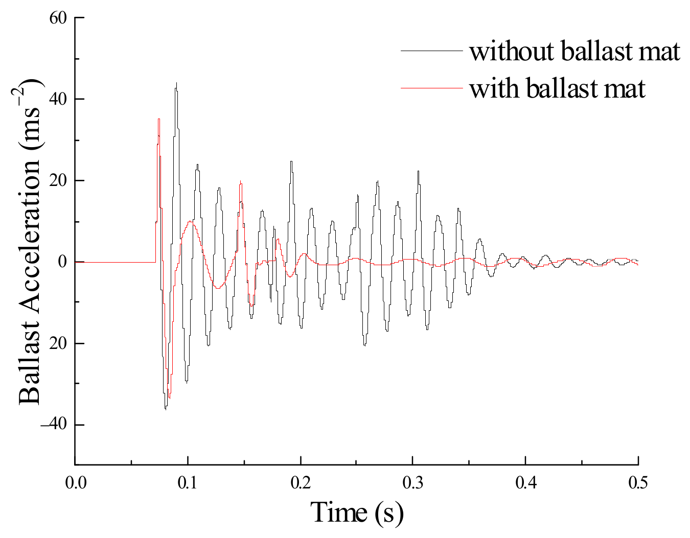
Figure 10 and Figure 11 compare the sleeper acceleration and ballast acceleration for tracks with and without the ballast mat. The first acceleration peak is a direct indicator of the impact force. The first acceleration peaks caused by the wheel impact are nearly the same for both cases. Nevertheless, the second acceleration peak for the case with the ballast mat appears smaller than that without the mat.
The ratios between the first acceleration peak on the first and second wheel impacts are shown in Figure 11 and presented in Table 2, where a larger ratio indicates a better vibration reduction. The results from Table 2 indicate that the ratios for the case with ballast mat are all higher than those for the case without mat, which demonstrates that the installation of the ballast mat can provide higher resilience and elasticity for the ballasted track. Figure 12 also shows that the ratio increases less for the sleeper, indicating that the ballast mat is better to reduce vibration on the rail and ballast than on the sleeper.
3.2. Track Dynamics in Frequency Domain
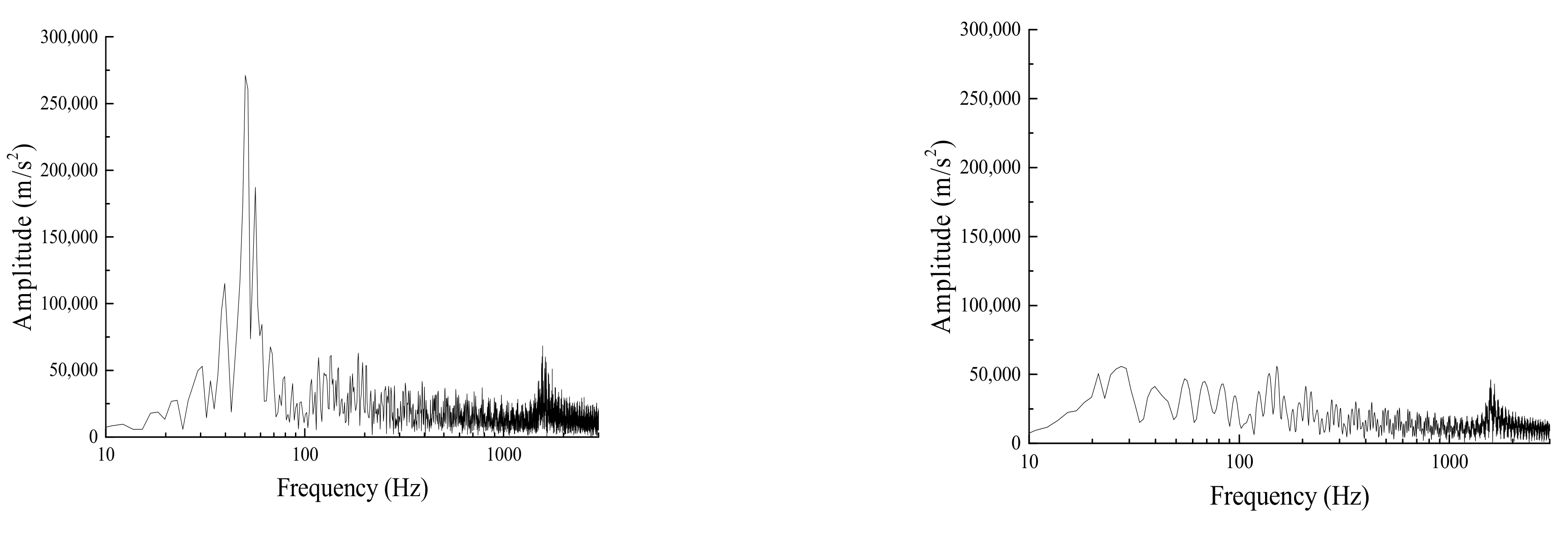
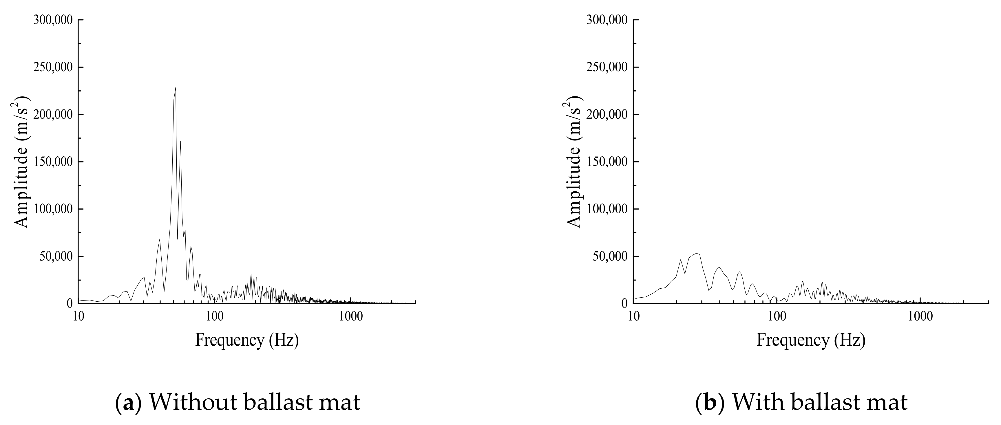
Figure 13, Figure 14 and Figure 15 show the power spectra of the rail, sleeper and ballast accelerations in the frequency domain. The results show that after the installation of the ballast mat, the rail vibration at approximately 50 Hz is significantly decreased, but the pinned–pinned resonance vibration remains nearly unchanged. For the sleeper and ballast, the vibration at approximately 50 Hz is mainly distributed when no ballast mat is present and is greatly attenuated when the ballast mat is installed.
3.3. Ballast Mat Insertion Loss
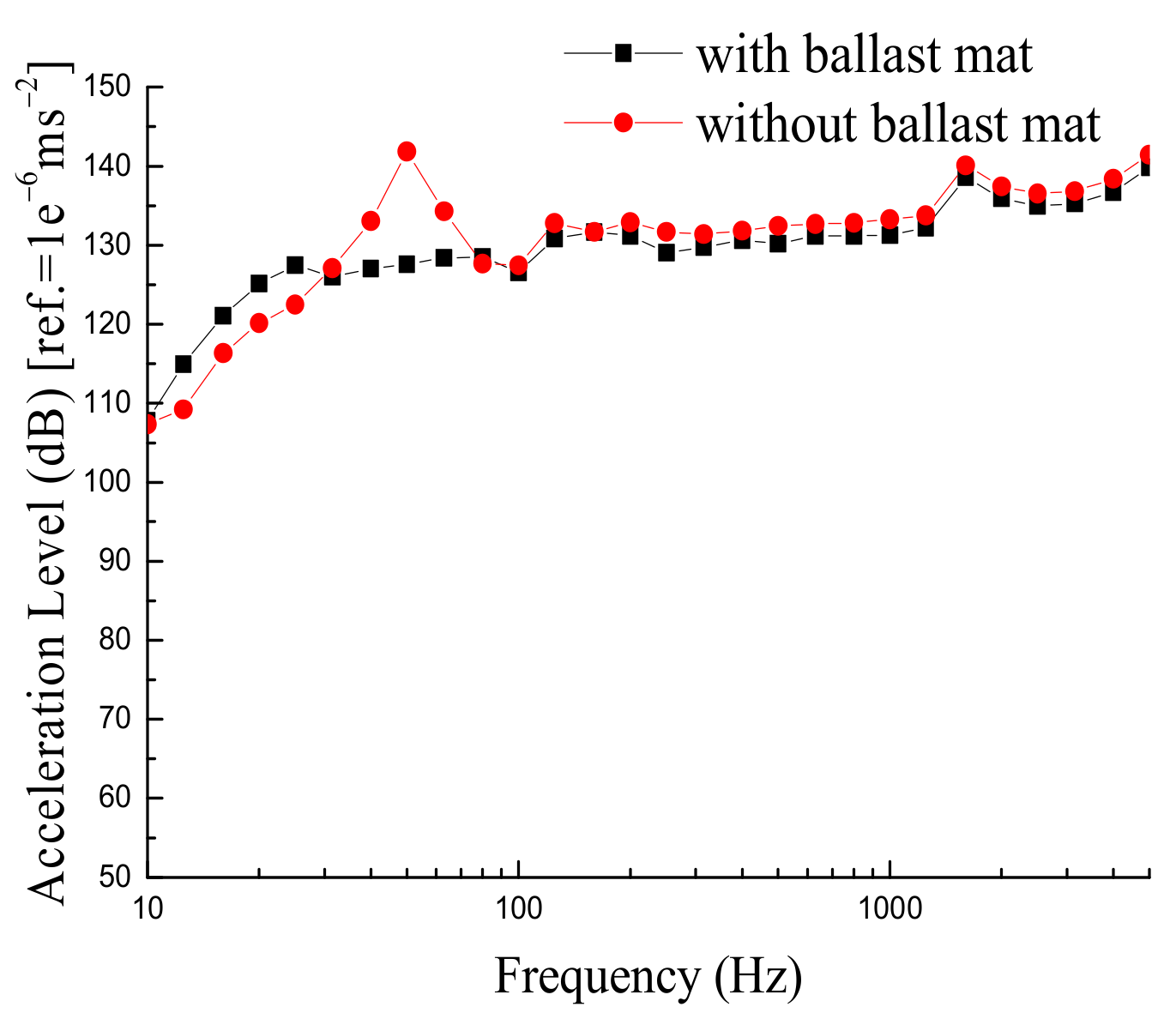
In this study, insertion loss is adopted as an indicator of how well the ballast mat reduces vibration. The effectiveness of vibration reduction in the frequency domain is studied based on the one-third octave analysis of the rail, sleeper and ballast accelerations. Figure 16, Figure 17 and Figure 18 show the vibration levels for the rail, sleeper and ballast for tracks with and without the ballast mat. Figure 19 shows the insertion losses of the rail, sleeper and ballast after the ballast mat is installed.
According to the one-third octave analysis, when the ballast mat is not installed, the main distribution frequency range of the acceleration level is 31.5–80 Hz, which is notably attenuated after the ballast mat being installed. The insertion losses of the rail, sleeper and ballast show that the ballast mat does not work effectively for all frequencies. For the low-frequency range of 0–40 Hz, using the ballast mat slightly amplifies the track vibration. Based on the model calculations, the vibration level is amplified by 5, 10 and nearly 15 dB for the rail, sleeper and ballast, respectively. For the mid-frequency range, the numerical analysis shows the best vibration reduction in the frequency range of 40 to 125 Hz. The vibration level is reduced by 15, 17 and nearly 13 dB for the rail, sleeper and ballast, respectively. For the high-frequency range, i.e., above 125 Hz, the ballast mat reduces the vibration on average by 3 to 4 dB.
4. Analysis of Insertion Loss Measurement by Field Tests
A wheelset drop test was performed on the connection line of Xuzhou East Station (China) to obtain rail and sleeper acceleration data. The wheelset weighs 1.2 tons and is lifted and dropped from a 25 mm height over the rail surface onto the mid-span between two sleepers. The equipment used for lifting and dropping the wheelset is shown in Figure 20A. The test segments consist of two ballasted tracks, one with and another without the ballast mat, on a concrete rail bridge. The track structure consists of a CHN60 rail, a type II elastic fastener, a type III concrete sleeper and a ballasted track bed with and without the ballast mat. Accelerometers are fixed on the rails and sleepers, as shown in Figure 20B,C. The accelerometers on the rail and sleeper can measure accelerations up to 1000 g and 100 g, respectively. The sampling rate was chosen as 10 kHz.
The insertion loss for each ballasted track component is calculated as the difference in the results of the one0third octave analysis of track vibration between the tracks with and without a ballast mat. A positive insertion loss means that the installation of the ballast mat can reduce track vibration, whereas zero or negative insertion loss means that the installation of ballast mat increases track vibration. The comparison of the measured insertion losses and the numerical results for both the rail and the sleeper are shown in Figure 21.
5. Conclusions
In this study, the vibration characteristics of ballasted tracks with and without a ballast mat are analysed using numerical simulations and field experiments with wheelset drop tests. The accelerations of the rail, sleeper and ballast in both the time and frequency domains prove that the installation of the ballast mat can enhance the resilience and elasticity of the ballasted track. The ballast mat can effectively reduce vibration at the mid- and high-frequency range of 40–3000 Hz with a maximum vibration reduction of 15–17 dB for different track components. In the low-frequency range, the ballast mat slightly amplifies the system vibrations by 5–15 dB for different track components. This is noteworthy because human activities are easily disturbed by vibrations in such low-frequency ranges and also because low-frequency vibrations can propagate for a long distance in soils and tunnels with little attenuation.
The wheelset drop test performed in this study indicates that it is an effective method to obtain the dynamic characteristics of track structures. The accelerations of the rail and sleeper are obtained through the test and the insertion losses of the rail and sleeper are obtained through the one-third octave analysis. The numerical insertion losses are compared with the experimental results, and a good agreement is found in the frequency range of 0 to 600 Hz. A slight difference exists between the predicted insertion losses and the measured data. The possible reason for the difference between the field test and numerical calculation results can be attributed to the intrinsic nature of the discreteness and randomness of the ballasted track bed [31,32]. Essentially, the ballasted track bed is consisted of granular particles of different sizes and is subjected to moving vehicle loads and maintenance loads such as tamping [33]. Thus, the system parameters cannot be easily taken as a uniform determined value and need further calibration by trial-and-error tests. The methodology proposed in this paper assumes that the ballasted track bed is regarded as the lumped-mass system [34] and certainly behaves slightly different from the discrete dynamical systems. However, the comparison results showed that even with this slight difference, the model established in this paper could grasp the intrinsic dynamic properties of the ballasted track system and showed good agreement with the test results. Future possible solutions can be achieved by carrying out simulations based on the discrete element method [35,36].
The spatial coupled wheel–track model defined in this study can simulate the wheelset drop test phenomenon, which opens perspectives for future developments. In particular, the track model can be extended to other aspects such as vehicle–track coupling dynamics.
Author Contributions
B.H.: writing—original draft, writing—review and editing, methodology and validation. D.W.: writing—original draft, software. B.W.: writing—review and editing. X.C.: investigation. J.P.: writing—review and editing. All authors have read and agreed to the published version of the manuscript.
Funding
The paper is supported by open project of the national key laboratory of the China Academy of Railway Sciences Co., Ltd. (2021YJ051), the China Railway Corporation Science and Technology Research and Development Program (N2018G071) and the National Natural Science Foundation of China (51708021).
Institutional Review Board Statement
Not applicable.
Informed Consent Statement
Not applicable.
Data Availability Statement
The data used to support the findings of this study are available from the corresponding author upon request.
Acknowledgments
The contribution of J. Pombo to this work was supported by FCT, through IDMEC, under LAETA, project UIDB/50022/2020.
Conflicts of Interest
The authors declare no conflict of interest.
References
- Indraratna, B.; Nimbalkar, S.; Rujikiatkamjorn, C. Modernisation of rail tracks for higher speeds and greater freight. Fac. Eng. Inf. Sci.-Pap. Part A 2013, 2, 1–20. [Google Scholar] [CrossRef]
- Kaewunruen, S.; Remennikov, A.M. Current state of practice in railway track vibration isolation: An Australian overview. Aust. J. Civ. Eng. 2016, 14, 63–71. [Google Scholar] [CrossRef]
- Omodaka, A.; Kumakura, T.; Konishi, T. Maintenance Reduction by the Development of Resilient Sleepers for Ballasted Track with Optimal Under-sleeper Pads. Procedia CIRP 2017, 59, 53–56. [Google Scholar] [CrossRef]
- Zbiciak, A.; Kraśkiewicz, C.; Oleksiewicz, W.; Lipko, C. Viscoelastic dynamic models of resilient elements used in railway tracks. MATEC Web Conf. 2016, 86, 1015. [Google Scholar] [CrossRef] [Green Version]
- Aydin, E.; Öztürk, B.; Dutkiewicz, M. Control of vibrations of multistorey buildings with use of passive dampers. In Proceedings of the 14th International Conference. Dynamical Systems-Theory and Applications, Lodz, Poland, 11–14 December 2017. [Google Scholar]
- Woodward, P.; Laghrouche, O.; Mezher, S.; Connolly, D. Application of Coupled Train-Track Modelling of Critical Speeds for High-Speed Trains using Three-Dimensional Non-Linear Finite Elements. Int. J. Railw. Technol. 2015, 4, 1–35. [Google Scholar] [CrossRef]
- Pombo, J.; Almeida, T.; Magalhães, H.; Antunes, P.; Ambrósio, J. Finite Element Methodology for Flexible Track Models in Railway Dynamics Applications. Int. J. Veh. Struct. Syst. 2013, 5, 43–52. [Google Scholar] [CrossRef]
- Mezher, S.B.; Connolly, D.P.; Woodward, P.K.; Laghrouche, O.; Pombo, J.; Costa, P.A. Railway critical velocity–Analytical prediction and analysis. Transp. Geotech. 2016, 6, 84–96. [Google Scholar] [CrossRef]
- Magalhães, H.; Ambrosio, J.; Pombo, J. Railway vehicle modelling for the vehicle–track interaction compatibility analysis. Proc. Inst. Mech. Eng. Part K J. Multi-Body Dyn. 2016, 230, 251–267. [Google Scholar] [CrossRef]
- Voivret, C.; Nhu, V.-H.; Perales, R. Discrete Element Method Simulation as a Key Tool Towards Performance Design of Ballasted Tracks. Int. J. Railw. Technol. 2016, 5, 83–98. [Google Scholar] [CrossRef]
- Hölscher, P. The Dynamics of Foundations for High Speed Lines on Soft Soils. Int. J. Railw. Technol. 2012, 1, 147–166. [Google Scholar] [CrossRef]
- Kuka, N.; Verardi, R.; Ariaudo, C.; Pombo, J. Impact of maintenance conditions of vehicle components on the vehicle–track interaction loads. Proc. Inst. Mech. Eng. Part C J. Mech. Eng. Sci. 2017, 232, 2626–2641. [Google Scholar] [CrossRef]
- Taforel, P.; Renouf, M.; Dubois, F.; Voivret, C. Finite Element-Discrete Element Coupling Strategies for the Modelling of Ballast-Soil Interaction. Int. J. Railw. Technol. 2015, 4, 73–95. [Google Scholar] [CrossRef] [Green Version]
- Momoya, Y.; Nakamura, T.; Fuchigami, S.; Takahashi, T. Improvement of Degraded Ballasted Track to Reduce Maintenance Work. Int. J. Railw. Technol. 2016, 5, 31–54. [Google Scholar] [CrossRef]
- Butorina, M.; Minina, N.; Ivanov, P.; Petryaev, A. Reduction of Vibroacoustic Effect of High-speed Trains. Procedia Eng. 2017, 189, 352–359. [Google Scholar] [CrossRef]
- Diego, S.; Casado, J.; Carrascal, I.; Ferreño, D.; Cardona, J.; Arcos, R. Numerical and experimental characterization of the mechanical behavior of a new recycled elastomer for vibration isolation in railway applications. Constr. Build. Mater. 2017, 134, 18–31. [Google Scholar] [CrossRef]
- Auersch, L. Static and dynamic behaviours of isolated or unisolated ballast tracks using a fast wavenumber domain method. Ingenieur-Archiv 2017, 87, 555–574. [Google Scholar] [CrossRef]
- Knothe, K.; Grassie, S.L. Modelling of Railway Track and Vehicle/Track Interaction at High Frequencies. Veh. Syst. Dyn. 1993, 22, 209–262. [Google Scholar] [CrossRef]
- Navaratnarajah, S.K.; Indraratna, B.; Nimbalkar, S. Application of Shock Mats in Rail Track Foundation Subjected to Dynamic Loads. Procedia Eng. 2016, 143, 1108–1119. [Google Scholar] [CrossRef] [Green Version]
- Navaratnarajah, S.K.; Indraratna, B. Use of Rubber Mats to Improve the Deformation and Degradation Behavior of Rail Ballast under Cyclic Loading. J. Geotech. Geoenvironmental Eng. 2017, 143, 04017015. [Google Scholar] [CrossRef] [Green Version]
- Yokoyama, H.; Izumi, Y.; Watanabe, T. A Numerical Simulation Method for Ground and Building Vibration Based on Three Dimensional Dynamic Analysis. Q. Rep. RTRI 2016, 57, 151–157. [Google Scholar] [CrossRef] [Green Version]
- Sato, Y.; Morimura, T.; Watanabe, S. Theoretical Analyses and Experimental Results on Track Moduli with Use of Wheelset Drop Test. Veh. Syst. Dyn. 1995, 24, 164–179. [Google Scholar] [CrossRef]
- Liang, D.; Song, Y.; Sun, T.; Jin, X. Rigid-flexible coupling dynamic modeling and investigation of a redundantly actuated parallel manipulator with multiple actuation modes. J. Sound Vib. 2017, 403, 129–151. [Google Scholar] [CrossRef]
- Wallin, M.; Hamed, A.M.; Jayakumar, P.; Gorsich, D.J.; Letherwood, M.D.; Shabana, A.A. Evaluation of the accuracy of the rigid body approach in the prediction of the dynamic stresses of complex multibody systems. Int. J. Veh. Perform. 2016, 2, 140. [Google Scholar] [CrossRef]
- Schurr, D.; Holzwarth, P.; Eberhard, P. Investigation of dynamic stress recovery in elastic gear simulations using different reduction techniques. Comput. Mech. 2017, 62, 439–456. [Google Scholar] [CrossRef]
- Li, Y.; Xu, X.; Zhou, Y.; Cai, C.; Qin, J. An interactive method for the analysis of the simulation of vehicle–bridge coupling vibration using ANSYS and SIMPACK. Proc. Inst. Mech. Eng. Part F J. Rail Rapid Transit 2016, 232, 663–679. [Google Scholar] [CrossRef]
- Wei, L.; Zeng, J.; Chi, M.; Wang, J. Carbody elastic vibrations of high-speed vehicles caused by bogie hunting instability. Veh. Syst. Dyn. 2017, 35, 1–22. [Google Scholar] [CrossRef]
- Stadlmayr, D.; Witteveen, W.; Steiner, W. A generalized constraint reduction method for reduced order MBS models. Multibody Syst. Dyn. 2017, 41, 259–274. [Google Scholar] [CrossRef] [Green Version]
- He, X.; Gai, Y.; Wu, T. Simulation of Train-Bridge Interaction under Wind Loads: A Rigid-Flexible Coupling Approach. DEStech Trans. Eng. Technol. Res. 2017. [Google Scholar] [CrossRef]
- Knothe, K.; Strzyzakowski, Z.; Willner, K. Rail Vibrations in the High Frequency Range. J. Sound Vib. 1994, 169, 111–123. [Google Scholar] [CrossRef]
- Zhao, C.; Zhang, X.; Zhai, W. Discrete element simulation of ballast vibration of high-speed railway gravel. Chin. J. Comput. Mech. 2015, 5, 674–680. [Google Scholar]
- Yan, Y.; Zhao, C.; Li, Y.; Ji, S. Discrete Element Analysis of Railway Ballast Breaking Characteristics. Chin. J. Comput. Mech. 2017, 5, 615–622. [Google Scholar]
- Wang, Z.; Xu, Y.; Wang, H.; Qi, L.; Xu, Y. Research on the influence of the parameters of the tamping operation of large-scale road maintenance machinery on the tamping effect. Railw. Constr. 2020, 1, 129–133. [Google Scholar] [CrossRef]
- Zhai, W. Vehicle-Track Coupled Dynamics; Science Press: Beijing, China, 2015; Volume 1. [Google Scholar]
- Takeshima, M.; Asakura, T. Numerical simulation of vibration damping by granular materials. Appl. Acoust. 2020, 162, 107189. [Google Scholar] [CrossRef]
- Xiao, J.; Sun, S.; Zhang, X.; Zhang, D.; Wei, K.; Wang, Y. Macro and meso dynamic response of granular materials in ballastless track subgrade for high-speed railway. Int. J. Transp. Sci. Technol. 2020, 10, 313–328. [Google Scholar] [CrossRef]
Figure 1.
Cross section of ballasted track with ballast mat.

Figure 2.
Installation of ballast mat.

Figure 3.
Schematic diagram of coupled wheel–track model.

Figure 4.
Coupled wheel–track model.

Figure 5.
Receptance and phase angle at mid-span between sleepers.

Figure 6.
Receptance and phase angle at sleepers mid-span.

Figure 7.
Receptance and phase angle above sleepers.

Figure 8.
Wheel displacement for tracks with and without ballast mat.

Figure 9.
Rail acceleration for tracks with and without ballast mat.

Figure 10.
Sleeper acceleration for tracks with and without ballast mat.

Figure 11.
Ballast acceleration for tracks with and without ballast mat.

Figure 12.
Ratios of first acceleration peaks for first and second wheel impacts.

Figure 13.
Rail acceleration power spectra for tracks with and without ballast mat.

Figure 14.
Sleeper acceleration power spectra for tracks with and without ballast mat.

Figure 15.
Ballast acceleration power spectra for tracks with and without ballast mat.

Figure 16.
One–third octave analysis of rail vibration level.

Figure 17.
One–third octave analysis of sleeper vibration level.

Figure 18.
One–third octave analysis of ballast vibration level.

Figure 19.
Insertion loss of rail, sleeper, and ballast.

Figure 20.
Field test spot and equipment.

Figure 21.
One–third octave analysis of rail and sleeper insertion loss.


Table 1.
System parameters.
| Parameter | Value |
|---|---|
| Rail elastic modulus (N·m−2) | 2.059 × 10¹¹ |
| Moment of inertia of rail section (m4) | 3.217 × 10⁻⁵ |
| Rail mass per unit length (kg·m−1) | 60.64 |
| Sleeper mass (kg) | 125.5 |
| Vertical stiffness of fastening system (N·m−1) | 6.5 × 10⁷ |
| Vertical damping of fastening system (N·s·m−1) | 7.5 × 10⁴ |
| Lateral stiffness of fastening system (N·m−1) | 5.5 × 10⁶ |
| Lateral damping of fastening system (N·s·m−1) | 4.5 × 10³ |
| Sleeper spacing distance (m) | 0.6 |
| Ballast density (kg·m−3) | 1.8 × 10³ |
| Ballast elastic modulus (N·m−2) | 1.1 × 10⁸ |
| Ballast damping (N·s·m−1) | 5.88 × 10⁴ |
| Shear stiffness of ballast (N·m−1) | 7.84 × 10⁷ |
| Shear damping of ballast (N·s·m−1) | 8.0 × 10⁴ |
| Ballast height (m) | 0.45 |
| Stiffness of ballast mat (N·mm−3) | 0.02 |
| Damping of ballast mat (N·s·m−1) | 1.36 × 10⁶ |
| Subgrade elastic modulus (N·m−2) | 0.9 × 10⁸ |
| Stiffness of subgrade (N·m−1) | 7.75 ×10⁷ |
| Damping of subgrade (N·s·m−1) | 3.115 ×10⁴ |
| Wheel mass (kg) | 1.2 ×10³ |
| Wheel drop height (mm) | 25 |
Table 2.
First acceleration peaks caused by first and second wheel impacts and their ratios.
| Tracks without Ballast Mat | Tracks with Ballast Mat | |||||
|---|---|---|---|---|---|---|
| Unit | First Impact | Second Impact | Ratio | First Impact | Second Impact | Ratio |
| m·s−2 | m·s−2 | m·s−2 | m·s−2 | |||
| Rail | 2960.32 | 1644.15 | 1.80 | 2919.02 | 1281.84 | 2.28 |
| Sleeper | 80.62 | 40.96 | 1.96 | 80.69 | 38.70 | 2.09 |
| Ballast | 33.22 | 24.84 | 1.33 | 35.45 | 19.8125 | 1.79 |
Publisher’s Note: MDPI stays neutral with regard to jurisdictional claims in published maps and institutional affiliations. |
© 2022 by the authors. Licensee MDPI, Basel, Switzerland. This article is an open access article distributed under the terms and conditions of the Creative Commons Attribution (CC BY) license (https://creativecommons.org/licenses/by/4.0/).
Share and Cite
MDPI and ACS Style
Hou, B.; Wang, D.; Wang, B.; Chen, X.; Pombo, J. Vibration Reduction in Ballasted Track Using Ballast Mat: Numerical and Experimental Evaluation by Wheelset Drop Test. Appl. Sci. 2022, 12, 1844. https://doi.org/10.3390/app12041844
AMA Style
Hou B, Wang D, Wang B, Chen X, Pombo J. Vibration Reduction in Ballasted Track Using Ballast Mat: Numerical and Experimental Evaluation by Wheelset Drop Test. Applied Sciences. 2022; 12(4):1844. https://doi.org/10.3390/app12041844
Chicago/Turabian StyleHou, Bowen, Di Wang, Bingbing Wang, Xingyu Chen, and João Pombo. 2022. "Vibration Reduction in Ballasted Track Using Ballast Mat: Numerical and Experimental Evaluation by Wheelset Drop Test" Applied Sciences 12, no. 4: 1844. https://doi.org/10.3390/app12041844
Note that from the first issue of 2016, this journal uses article numbers instead of page numbers. See further details here.