

Performance Improvement of Microchannel Heat Exchangers with Modified Louver Fins under Frosting Conditions
Department of Refrigeration and Cryogenic Engineering, School of Energy and Power Engineering, Xi’an Jiaotong University, Xi’an 710049, China
*
Author to whom correspondence should be addressed.
Appl. Sci. 2023, 13(11), 6378; https://doi.org/10.3390/app13116378
Submission received: 5 May 2023
/
Revised: 21 May 2023
/
Accepted: 22 May 2023
/
Published: 23 May 2023
(This article belongs to the Topic Enhanced Heat Transfer and Advanced Energy Conversion Technology)
Abstract
:Microchannel heat exchangers (MCHX) are increasingly being used in refrigeration and heat pumps due to their superior thermal-hydraulic properties. However, when the MCHX surface temperature drops below the freezing point, frost will accumulate on the fin surface, which significantly affects the heat transfer performance. In this study, a modified MCHX with extended windward fins was developed to improve the frosting performance. The thermal-hydraulic performance of the modified MCHX and conventional MCHX were compared and evaluated under frosting conditions. Results show that the extended fins on the windward side capture a large amount of frost and delay the rapid blockage of air flow passage by frost. The modified MCHX structure makes the frost more evenly distributed. During the 60 min frosting cycle, the total heat transfer capacity and the mass of the accumulated frost of the modified MCHX are 9.6–49.7% and 10.3–46.9% higher than the conventional MCHX, respectively. Furthermore, the modified MCHX has greater potential to improve the thermal-hydraulic performance under the condition of more uneven frost layer distribution. The purpose of this work is to provide useful guidance for the optimal design of MCHX under frosting conditions.
1. Introduction
Under the background of carbon peaking and carbon neutrality, the application of microchannel heat exchangers (MCHXs) in refrigeration and heat pump systems has become a research hotspot. Compared with the conventional fin-and-tube heat exchanger (FTHX), the MCHX has the advantages of higher heat transfer efficiency [1,2], less refrigerant charging [3], and lower cost [4,5]. However, when the MCHX works in the winter, the frost will form and accumulate faster on the fin surface [6,7], which will lead to a decrease in airflow rate and an increase in the thermal resistance, thus reducing the heating capacities of the heat pump units [8,9,10]. This is because the louver fins have many edges and corners, which can serve as frost nucleation points in the frosting process [11,12]. In addition, the smaller louver fin pitch facilitates the formation of ice bridges, thus potentially promoting the frost layer growth rate [13].
The frosting characteristics of MCHXs have been studied extensively. Some studies [14] have explored the effects of surface temperature and air environmental conditions on the frost accumulation rate of MCHXs. They claimed that surface temperature and relative humidity (RH) were the main influencing parameters. The effect of fouling on the frost growth of MCHX was reported by Hu et al. [15]. Results show that the light fouling (20 g) increased the heat transfer rate and the frost accumulation rate, while heavier fouling showed the opposite conclusion. In addition, some studies have shown that the poor drainage performance of the MCHX causes more residual water on the fin surface, resulting in the rapid decline of the heat exchange performance during re-frosting [16]. Moreover, the poor drainage performance of the MCHX will prolong the defrosting time, making its defrosting efficiency 22.5% lower than that of the FTHX [17].
To better inhibit frost growth and promote the removal of residual water, many studies have investigated the structural characteristics of the MCHXs. Hrnjak et al. [18] found that MCHXs with a larger louver angle (39°) had a more desirable behavior after several frosting periods in terms of the thermal and drainage performance. The influence of flat tube arrangement direction on the periodic frosting and defrosting cycle performance of MCHX was investigated experimentally by Xu et al. [19]. Compared with the horizontal orientation, the vertical orientation had a better drainage performance and a longer frosting period. Zhang et al. [20] found that using a parallel fin instead of the louvered fin in MCHXs could enhance its drainage performance and extend its frosting cycle. Kim et al. [21] proposed an asymmetric louver fin, which enhanced the drainage performance and the thermal performance of the MCHXs heat pump system under periodic frosting conditions. Xu et al. [22] presented a modified MCHX and compared it with the conventional wavy fin MCHX. The study showed that the modified wavy fin MCHX with drainage function had the best performance under wet and frosted conditions. Park et al. [23] proposed a new louver fin with an unequal louver pitch. Results illustrated that the frost layer distribution was more uniform, and the average heat transfer coefficient of MCHX was increased by 21% when the louver pitch successively decreased by 20%. Hu et al. [24] showed that the distribution of refrigerant directly affected the uniformity of frost distribution. The flat tubes of the MCHX were vertically arranged, and there was no partition in the header. The heat pump system would show higher performance and stability. Hong et al. [25] compared the heating capacity of the novel plain-louvered fin MCHX and the conventional MCHX under frosting conditions. The heating time and maximum heating capacity of the new plain louver fin MCHX were 102.7% and 14.0% higher than that of the corrugated louver fin MCHX, respectively.
Additionally, in practical applications, some studies have found that frost is mainly deposited on the windward side, causing the airflow passage to be blocked by frost quickly [26]. Kim et al. [27] performed an experimental investigation on the frosting characteristics of a two-layer FTHX with different refrigerant and airflow directions. Results reveal that the amount of frost accumulation on the front side was significantly different from that on the rear side. For a counter-flow heat exchanger, the blocking rate on the front side was 94%, and that on the rear side was only 77%. For a parallel-flow heat exchanger, the blocking rate on the front side was 98%, and that on the rear side was only 67%. The frost distribution characteristics of MCHX were investigated experimentally by Park et al. [28]. Results reveal that the blocking rate of the windward side was 100%, and the leeward side was only 68% when frosting for 200 min. Furthermore, Park et al. [28] claimed that optimizing the fin shape on the windward side plays a key role in improving the thermal performance of the MCHX. Park et al. [29] carried out an experimental study on the frost formation of a louver fin with vortex generators. Results show that the vortex generators can reduce the blocking rate of the front side by 15%, and the heat transfer performance could be improved by 28%. Kim et al. [30] also found that frost growth is mainly on the front side; reducing fin density and increasing louver pitch could effectively improve the frosting uniformity.
As demonstrated above, the frost blocking on the front side louver fin is the main factor that reduces the heat transfer rates of MCHX. Delaying the fast blocking on the front side is a very effective method to improve the frosting performance of MCHX. However, for the design of the MCHX, to pursue a compact structure, the windward side fin area is often smaller [31]. This will cause frost to quickly block the spaces between the louvers on the front side, and the louver fins on the rear side will not effectively work anymore. To delay frost blocking on the front side, increasing the fin area on the windward side is an effective method. For MCHX, this method has not been reported in the literature. Therefore, it is necessary to improve the structure of the louver fin to be suitable for frosting conditions. The purpose of this study is to propose a modified louver fin to improve the frosting performance of MCHX.
In this study, a modified louver fin MCHX was developed to improve its thermal-hydraulic performance under frosting conditions. The modification scheme is to lengthen the fin length on the windward side. The heat transfer and pressure drop performance of the novel design MCHX was compared with the conventional MCHX under frosting conditions. Moreover, the influences of air velocity, RH, and inlet coolant temperature on the heat transfer rate, frost accumulation rate, and pressure drop behavior were conducted. The results can provide useful guidance for the optimization of the MCHXs under frosting conditions.
2. Experimental Setup and Measurement
2.1. Testing Setup Description
The experiment was carried out in an environmental chamber, which could maintain a relatively stable environment and meet the experimental test conditions. Air conditioning systems and heaters are used to maintain the environment. The temperature deviation of the environmental chamber was maintained at ±0.1 °C, and the RH deviation was maintained at ±3% RH.
Figure 1 illustrates a schematic diagram of the experimental setup, which contains an air duct, a thermostatic water tank, a test sample, and data acquisition systems. The test sample was installed in the middle of the air duct. The experiment used a fan to drive moist air into the air duct system, and the speed of the fan was controlled by a transducer. A CCD camera mounted on one side of the duct was used to observe the frosting. Straighteners were installed on both sides of the sample to reduce eddy currents for uniform air distribution. A heater was installed at the air duct entrance to provide heat for MCHX defrosting. The temperature and RH sensors were inserted into the duct to measure the air temperature and RH at the inlet and outlet of the test sample. The air velocity was measured by a hot-wire anemometer. The pressure difference between the inlet and outlet of the test sample was measured by a differential pressure sensor. The pressure sensor has a measurement range of 0–200 Pa and an accuracy of 0.1% of full scale. In the refrigerator thermostat, 40% ethylene glycol aqueous solution was used as the coolant, and the lowest temperature could reach −40 °C without phase change. The T-type thermocouple with an accuracy of ±0.5 °C was placed on the surface of the inlet and outlet tubes to measure the temperature of the fluid entering and exiting the MCHX.
The two types of MCHXs used in this experiment are shown in Figure 2. In one MCHX, the fins on the windward side were lengthened; that is, the fins extended 4 mm beyond the flat tube, while the leeward fins were flush with the flat tube. In the other MCHX, the windward fins were flush with the flat tube, while the leeward fins were extended. This fin shape is a serpentine louver fin. The flat tubes were arranged vertically, and the fins were arranged between the flat tubes. This installation was more conducive to the downward flow of melted frost. The geometric parameters of the MCHXs are described in Table 1.
Table 2 shows the test conditions. The experiments were performed for different inlet refrigerant temperatures (−7 °C and −10 °C), RH (80% and 90%), and the inlet air temperature fixed at 2 ℃. In addition, the inlet air velocity was 0.6 m/s, 1.0 m/s, and 1.5 m/s, respectively. After MCHX worked in frosting condition for one hour, the thermostatic water tank was turned off, the heater was turned on, and the fan speed was set to the minimum for defrosting operation for 10 min. The specifications of the test instruments are shown in Table 3.
2.2. Data Reduction
The mass of accumulated frost can be calculated by Equations (1)–(3):
where is the air mass flow rate in ; and are the air humidity ratio at the inlet and outlet, respectively, in ; is the air density in ; is the air volume flow rate in ; A is the area of the air duct in ; and is the air velocity in .
The air humidity ratio can be obtained by the pressure and RH, as shown in Equation (4) [32]:
where is the air RH, is the saturation pressure of water vapor, .
The coolant used in this study has no phase transition; the heat transfer on the coolant side can be calculated by Equation (5).
where is the coolant mass flow rate in ; is the specific heat of the coolant in ; and are the temperature of the coolant at the inlet and outlet, respectively. The air-side heat transfer and the coolant-side heat transfer were verified and their deviation was within ±5%.
Air side heat transfer rate:
where is the air-specific enthalpy at the inlet of the air duct in , is the air-specific enthalpy at the outlet of the air duct in . It can be calculated by Equation (7) [15]:
The heat transfer capacity is defined as the total heat transfer over the whole frosting cycle, which is expressed as [32]:
2.3. Uncertainty Analysis
The uncertainty of all parameters was calculated using the method proposed by Robert J [33]. The calculated parameter R has the following functional relationship with a series of directly measured parameters (X1, X2, X3, …, XN):
The relative uncertainty of indirectly measured parameters can be calculated by Equation (10).
According to Equations (9) and (10), the relative uncertainties of the pressure drops, frost formation rate, and heat transfer rate are calculated as follows:
According to the above formulas and the calculation method of each measurement parameter, the relative uncertainty of each measurement parameter in this study is obtained and summarized in Table 4.
3. Results and Discussion
The effects of air velocity, inlet coolant temperature, RH, and windward side fin structure on heat transfer rate, frost accumulation rate, and pressure drop behavior are reported. Section 3.1 describes frost growth behavior on the windward side of the two MCHXs. Section 3.2, Section 3.3 and Section 3.4 analyzed the time-varying heat transfer rate, frost accumulation rate, and pressure drop characteristics of the two experimental MCHXs under different frosting conditions during the 60 min frosting period. For brevity, the MCHX with extended windward fins is called MCHX-A, and the MCHX with windward fins flush with flat tubes is called MCHX-B.
3.1. Frost Growth Behavior Analysis
The eight pictures in Figure 3 show the frost growth characteristic of the two heat exchangers at different time points. The experiment was carried out at an inlet temperature of 2 °C, an inlet velocity of 1.5 m/s, an RH of 90%, and an inlet coolant temperature of −7 °C. At 2 min, the frost first formed at the base of the fin due to the low temperature of the fin base. Over time, the fin tips became colder, and the frost gradually spread from the base of the fin to the tip; at 15 min, the windward-lengthened fins were covered with frost. By comparing these pictures, we can see that the frost blockage of the MCHX-A was not as severe as that of the MCHX-B. At 30 min, the frost-blocking situation of the MCHX-B was much more severe than that of the MCHX-A. At 60 min, the extended fins captured a large amount of frost, and the airflow passage was not completely blocked. However, the airflow passage of the MCHX-B was nearly blocked by the frost.
Figure 4 depicts the frost growth of the two heat exchangers at the early and late stages based on frosting photos. In the early stages of frosting, frost usually forms where the fin and the flat tube are in contact because the temperature is lower there. As the frosting progresses, thermal resistance develops where the fin and the flat tube are in contact, and heat begins to transfer more to the fin away from the flat tube. Therefore, the extended portion of the windward side fins begins to capture frost. During the late stage of frosting, extended fins capture large amounts of frost to a degree that makes the frost distribution more even, thus inhibiting rapid blocking on the front side. However, for the MCHX-B, the frost layer quickly forms on the front side and blocks the airflow passage, resulting in the deterioration of the heat transfer rate.
3.2. Heat Transfer Analysis
The heat transfer rate and overall heat transfer capacity of the two MCHXs are shown in Figure 5 and Figure 6, respectively. As expected, the higher RH caused a rapid decrease in the heat transfer rate. This is because with the increase of RH, the moisture content of the inlet air increases, thus improving the mass transfer potential. With the increase of mass transfer potential, the frosting rate is accelerated, and the heat transfer rate is rapidly reduced. On the whole, RH had a significant effect on the heat transfer rate. The comparison between Figure 5a,b shows that when the inlet coolant temperature was −10 °C, at RH = 90%, the heat transfer rate dropped rapidly after 10 min, while at RH = 80%, the heat transfer rate dropped slowly after 20 min. In addition, the comparison between Figure 5c,d shows that when the inlet coolant temperature was −7 °C, at RH = 90%, the heat transfer rate dropped rapidly after 15 min, while at RH = 80%, the heat transfer rate dropped slowly after 25 min. From the above analysis, it can be concluded that when RH increases, the growth of the frost layer is significantly promoted, thus worsening the heat transfer rate. Furthermore, the coolant inlet temperature has a significant effect on the heat transfer rate. By comparing Figure 5a,c, Figure 5b,d, it can be concluded that at lower inlet coolant temperature, the heat transfer rate of the heat exchanger declines earlier, and the decline trend is more obvious. This is because the temperature difference between the fin surface and the air increases, leading to the rapid growth of the frost layer, which deteriorates the heat transfer of the heat exchanger.
As expected, the heat transfer capacity of MCHX-A is greater than that of MCHX-B. As discussed in Section 3.1, the extended fins delay frost blocking and maintain a better heat transfer rate throughout the frost cycle. The overall heat transfer capacity of MCHX-A was 9.6–49.7% higher than that of MCHX-B under different frosting conditions. Moreover, the heat transfer capacity of MCHX-A at lower air velocity (0.6 m/s) increased the most compared with that of MCXH-B at four frosting conditions, as shown in Figure 6. With the increase of ua, the proportion of improvement gradually decreased. This is because when ua decreased, the air momentum also decreased, and the frost growth rate on the rear side slowed, while the frost growth on the front side had an insignificant influence, resulting in a more uneven distribution of the frost layer [30]. The MCHX with fins extended on the windward side can effectively improve the frosting uniformity, and the worse the frosting uniformity, the greater the potential for improvement. With the increase of ua, frost uniformity increased, and the potential of MCHX-A to improve heat transfer performance decreased. Moreover, when the inlet coolant temperature and RH changed to promote frost growth, the growth of the frost on the front side would be more active, resulting in a larger decrease in air humidity passing through the rear side; the driving force of the frost growth on the rear side was reduced. Therefore, the distribution uniformity of the frost layer was worse. As shown in Figure 6b, the more serious the frost condition, the more uneven the frost layer distribution. Therefore, MCHX-A has the greatest potential to improve thermal performance, and the overall thermal performance is improved by more than 27%.
As discussed above, lower surface temperatures and higher RH promote the growth of windward frosting layers and make frosting less uniform. However, the higher inlet air velocity resulted in better frosting uniformity on the heat exchanger. Under the condition of poor frosting uniformity, the MCHX with lengthened fins on the windward side has greater potential to improve thermal performance. Therefore, in this study, the MCHX-A can improve the heat transfer capacity by a maximum of 49.7% compared with MCHX-B in Tc,in = −10 °C, RH = 90%, and ua = 0.6 m/s. Meanwhile, the MCHX-A can improve the thermal performance by a minimum of 9.6% compared with MCHX-B in Tc,in = −7 °C, RH = 80%, and ua = 1.5 m/s. In summary, the heat exchanger with extended fins on the windward side can make the frosting more uniform, reduce blocking on the frost side, and show better thermal performance under frosting conditions.
3.3. Analysis of Frost Growth Rate
The frost accumulation rate and the total amount of frost of the two MCHXs are shown in Figure 7 and Figure 8, respectively. It can be noticed from Figure 7 that the RH had a significant impact on the frost rate. This is because a higher RH will carry more moisture, increasing the mass transfer coefficient and promoting the accumulation of frost. Comparing Figure 7a,b, for all inlet air velocity (0.6 m/s, 1 m/s, 1.5 m/s), the mass of frost at RH = 90% is 33.0–50.2% greater than that of the RH = 80% at 10 min. Similarly, compared with Figure 7c,d, at RH = 90%, an increase in the mass of frost of 18.8–61.2% was observed as compared to RH = 80% at 10 min. However, in the case of a larger early frost rate, the airflow passage will be blocked faster, and the frost accumulation rate will enter into a slow growth earlier. Furthermore, the inlet temperature of the coolant also had a significant influence on the frost accumulation rate. For all inlet air velocity (0.6 m/s, 1 m/s, 1.5 m/s) and the air RH (80% and 90%), the frost accumulation at Tc,in = −10 °C was 7.0–19.1% higher than that of the Tc,in = −7 °C at 10 min. Besides, with the increase of ua, the amount of frost on the fin surface will increase significantly. Irrespective of the inlet coolant temperature and RH, the impact of wind speed on the mass of frost was more significant. For all the inlet coolant temperatures (−7 °C and −10 °C) and the inlet relative humidity (RH = 80% and RH = 90%), the mass of frost at ua = 1.0 m/s was 21.9–64.7% higher than that of the ua = 0.6 m/s. Similarly, at ua = 1.5 m/s, an increase in mass of frost of 74.8–94.2% and 17.9–46.7% was observed as compared to ua = 0.6 m/s and ua = 1.5 m/s, respectively. As discussed earlier, the increase in air velocity can make the frost distribution more uniform, so more frost can be attached to the fin surface. On the other hand, the increase of ua can make the frost density larger, thus increasing the mass of the frost.
It can be seen in Figure 8 that the frost accumulation of MCHX-A was always larger than that of MCHX-B under different frosting conditions. This is mainly influenced by: (1) The extended fins on the windward side catch a lot of frost. (2) The fins extending on the windward side make the heat exchanger frosting more uniform. The overall frost accumulation of MCHX-A is 10.3–46.9% higher than that of MCHX-B under different frosting conditions. In general, the frost accumulation of MCHX-A at lower air velocity (0.6 m/s) increased the most compared with that of MCXH-B at four frosting conditions. With the increase of ua, the proportion of improvement gradually decreased. This trend was similar to that of the heat transfer capacity. This is because, with the increase of ua, the frost uniformity increased, so the extended fins on the windward side promoted the frost uniformity potential to be relatively reduced. In addition, under the condition that the RH and inlet coolant temperature changed to promote frost growth, compared with MCHX-B, the MCHX-A had a greater increase in frosting mass. In general, due to the higher heat transfer capacity of MCHX-A, the accumulation of frost on MCHX-A was bound to be greater, but the increased frost was more evenly distributed on the fin, so its frosting performance was better.
3.4. Pressure Drop Analysis
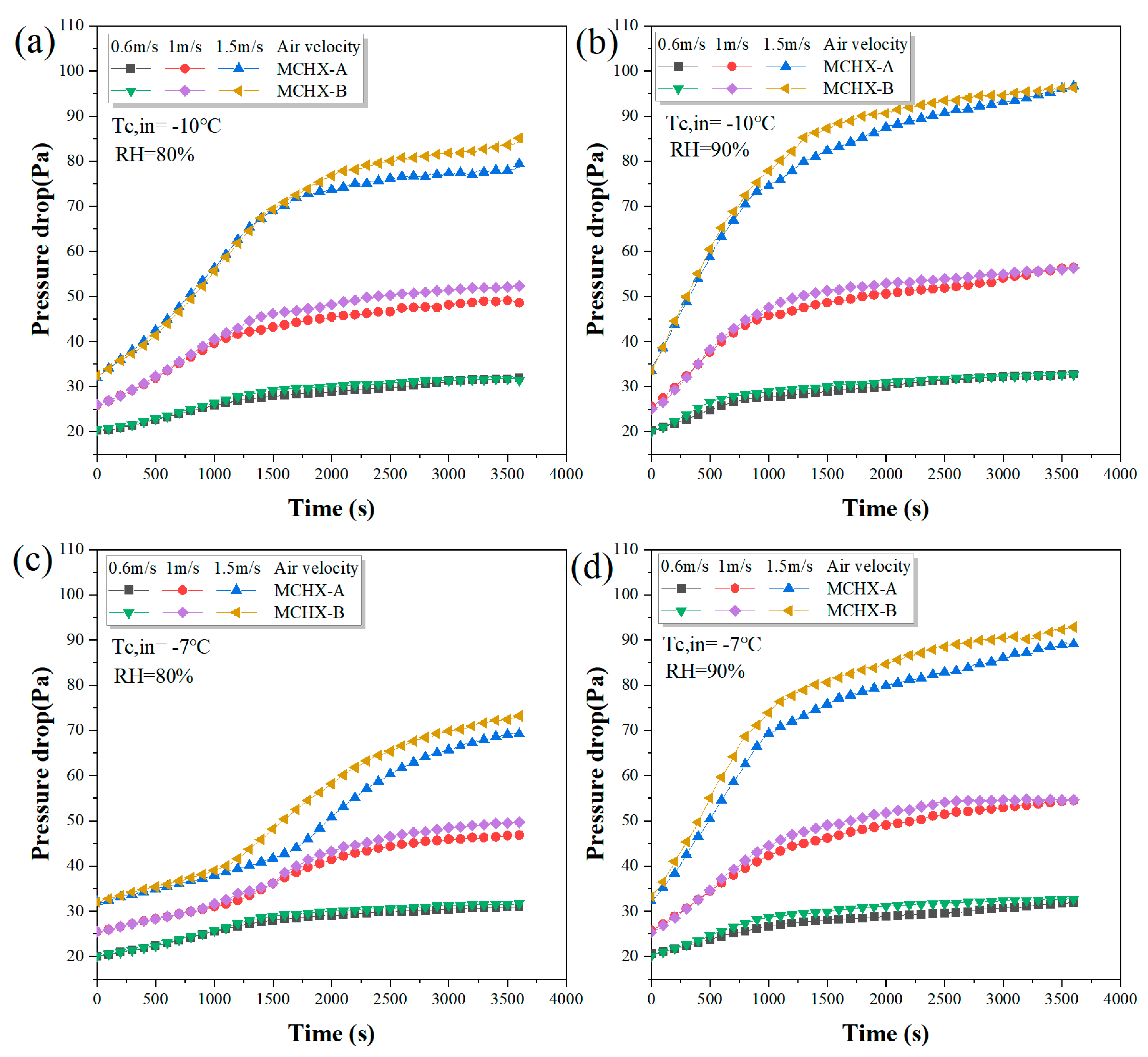
The air-side pressure drops of the two MCHXs are compared in Figure 9. The rapid growth of the frost layer led to a blockage of the free airflow passage, resulting in the rapid rise of the air-side pressure drop. As discussed earlier, RH has a significant effect on the frost accumulation rate and heat transfer rate. Similarly, RH also has a significant effect on the rate of increase in pressure drop. Irrespective of the inlet coolant temperature, air velocity, and fin structures, the effect of RH on pressure drop is significant. It can be seen from Figure 9b, d that the pressure drop increases rapidly in the early frosting stage. The pressure drops for RH = 90% are about 16.5–98.1% higher than that of RH = 80% at 20 min. At a higher RH, the increase in frost growth rate led to the increased air-side pressure drop. The impact of air velocity on pressure drop was also obvious, and the pressure drop increased with the increase in air velocity. For all the experimental conditions, the pressure drop at ua = 1 m/s was 26.1–56.4% higher than that of the ua = 0.6 m/s. Similarly, at ua = 1.5 m/s, an increase in pressure drops of 60.6–195.4% and 27.3–71.3% was observed as compared to ua = 0.6 m/s and ua = 1 m/s, respectively. The inlet air velocity had the greatest effect on pressure drop.
As expected, the pressure drop of MCHX-B was usually greater than that of MCHX-A because MCHX-A has a smaller blocking ratio than MCHX-B during frosting. MCHX-B can have a maximum pressure drop difference of 8 Pa greater than MCHX-A under all frosting conditions. The difference in pressure drop between two heat exchangers is affected by frosting conditions and frosting time. In summary, it is shown that the MCHX with extended fins on the windward side can effectively delay the frost-blocking rate and reduce the pressure drop.
4. Conclusions
In this study, a modified MCHX was proposed to improve heat exchanger frosting performance by extending the fins on the windward side. The heat transfer rate, frost accumulation rate, and pressure drop characteristics of the MCHX-A were measured and compared with the MCHX-B under different frosting conditions. Based on this experimental analysis, the main conclusions are as follows:
- (1)
- Frost is mainly deposited on the windward side of the heat exchanger. Extending the length of windward fins can effectively capture a large amount of frost and make the frost distribution more uniform, thus inhibiting rapid frost blocking on the front side.
- (2)
- In the early stage of frosting, frost mainly grows in the area where the fin and the flat tube are in contact because of the lower surface temperature. As the frost progresses, the extended fins on the windward side begin to capture the frost. Therefore, the heat transfer rate of the MCHX-A is nearly the same as that of the MCHX-B at the early frosting stage, and the former shows better heat transfer performance than the latter as the frost progresses.
- (3)
- During the 60 min frosting cycle, the total heat transfer capacity and the mass of frost of the MCHX-A are 9.6–49.7% and 10.3–46.9% higher than the MCHX-B, respectively. In addition, the pressure drop of MCHX-B is larger than that of MCHX-A under all frosting conditions. This is mainly because the extended fins on the windward side capture a large amount of frost, which reduces the airflow attenuation rate and increases the heat transfer rate and frost accumulation rate of the heat exchanger.
- (4)
- The MCHX-A has greater potential to improve the thermal-hydraulic performance of MCHX at lower air velocity (0.6 m/s), where the frost layer distribution is more uneven. With the increase of air velocity, the frost layer uniformity is improved, and the proportion of MCHX-A improving heat transfer performance decreases gradually. In addition, as the inlet coolant temperature and RH change to promote frost layer growth, the potential of MCHX-A to improve heat transfer capacity increases. In conclusion, the more uneven the frost layer distribution, the greater the potential of MCHX-A to improve the heat transfer performance.
Author Contributions
Methodology, T.X.; Formal analysis, G.Y.; Data curation, T.X.; Writing–original draft, T.X.; Writing – review & editing, G.L.; Supervision, G.Y.; Funding acquisition, G.L. All authors have read and agreed to the published version of the manuscript.
Funding
This research received no external funding.
Institutional Review Board Statement
Not applicable.
Informed Consent Statement
Not applicable.
Data Availability Statement
Data is contained within the article.
Conflicts of Interest
The authors declare no conflict of interest.
References
- Khan, M.G.; Fartaj, A. A review on microchannel heat exchangers and potential applications. Int. J. Energy Res. 2011, 35, 553–582. [Google Scholar] [CrossRef]
- Dash, B.; Nanda, J.; Rout, S.K. The role of microchannel geometry selection on heat transfer enhancement in heat sinks: A review. Heat Transf. 2021, 51, 1406–1424. [Google Scholar] [CrossRef]
- Wang, Y.; Zong, S.; Song, Y.; Cao, F.; He, Y.; Gao, Q. Experimental and techno-economic analysis of transcritical CO2 heat pump water heater with fin-and-tube and microchannel heat exchanger. Appl. Therm. Eng. 2021, 199, 117606. [Google Scholar] [CrossRef]
- Shen, B.; Fricke, B. Development of high efficiency window air conditioner using propane under limited charge. Appl. Therm. Eng. 2020, 166, 114662. [Google Scholar] [CrossRef]
- Illán-Gómez, F.; García-Cascales, J.R.; Hidalgo-Mompeán, F.; López-Belchí, A. Experimental assessment of the replacement of a conventional fin-and-tube condenser by a minichannel heat exchanger in an air/water chiller for residential air conditioning. Energy Build. 2017, 144, 104–116. [Google Scholar] [CrossRef]
- Padhmanabhan, S.; Cremaschi, L.; Fisher, D. Comparison of Frost and Defrost Performance between Microchannel Coil and Fin-and-Tube Coil for Heat Pump Systems. Int. J. Air-Cond. Refrig. 2012, 19, 273–284. [Google Scholar] [CrossRef]
- Shao, L.-L.; Yang, L.; Zhang, C.-L. Comparison of heat pump performance using fin-and-tube and microchannel heat exchangers under frost conditions. Appl. Energy 2010, 87, 1187–1197. [Google Scholar] [CrossRef]
- Brignoli, R.; Cecchinato, L.; Zilio, C. Experimental analysis of an air–water heat pump with micro-channel heat exchanger. Appl. Therm. Eng. 2013, 50, 1119–1130. [Google Scholar] [CrossRef]
- Song, M.; Deng, S.; Dang, C.; Mao, N.; Wang, Z. Review on improvement for air source heat pump units during frosting and defrosting. Appl. Energy 2018, 211, 1150–1170. [Google Scholar] [CrossRef]
- Zhou, C.; Ye, S.; Ni, L.; Yao, Y. A review of heat pump research in China using bibliometric methods. J. Renew. Sustain. Energy 2022, 14, 012701. [Google Scholar] [CrossRef]
- Yang, S.; Wu, C.; Zhao, G.; Sun, J.; Yao, X.; Ma, X.; Wang, Z. Condensation frosting and passive anti-frosting. Cell Rep. Phys. Sci. 2021, 2, 100474. [Google Scholar] [CrossRef]
- Sheng, W.; Li, X.; Wang, R.; Dang, C.; Song, M. Condensate drainage on slit or louvered fins in microchannel heat exchangers for anti-frosting. Energy Build. 2020, 223, 110215. [Google Scholar] [CrossRef]
- Li, K.; Xia, D.; Luo, S.; Zhao, Y.; Tu, R.; Zhou, X.; Zhang, H.; Su, L. An experimental investigation on the frosting and defrosting process of an outdoor heat exchanger in an air conditioning heat pump system for electric vehicles. Appl. Therm. Eng. 2022, 201, 117766. [Google Scholar] [CrossRef]
- Moallem, E.; Hong, T.; Cremaschi, L.; Fisher, D.E. Experimental investigation of adverse effect of frost formation on microchannel evaporators, part 1: Effect of fin geometry and environmental effects. Int. J. Refrig. 2013, 36, 1762–1775. [Google Scholar] [CrossRef]
- Hu, Y.; Yuill, D.P.; Ebrahimifakhar, A. The effects of outdoor air-side fouling on frost growth and heat transfer characteristics of a microchannel heat exchanger: An experimental study. Int. J. Heat Mass Transf. 2020, 151, 119423. [Google Scholar] [CrossRef]
- Xia, Y.; Zhong, Y.; Hrnjak, P.S.; Jacobi, A.M. Frost, defrost, and refrost and its impact on the air-side thermal-hydraulic performance of louvered-fin, flat-tube heat exchangers. Int. J. Refrig. 2006, 29, 1066–1079. [Google Scholar] [CrossRef]
- Xiong, T.; Ying, Y.; Han, B.; Yan, G.; Yu, J. Comparison of energy supplies and consumptions in heat pump systems using finned tube and microchannel heat exchangers during defrosting. Int. J. Refrig. 2021, 132, 222–232. [Google Scholar] [CrossRef]
- Hrnjak, P.; Zhang, P.; Rennels, C. Effect of louver angle on performance of heat exchanger with serpentine fins and flat tubes in frosting: Importance of experiments in periodic frosting. Int. J. Refrig. 2017, 84, 321–335. [Google Scholar] [CrossRef]
- Xu, B.; Han, Q.; Chen, J.; Li, F.; Wang, N.; Li, D.; Pan, X. Experimental investigation of frost and defrost performance of microchannel heat exchangers for heat pump systems. Appl. Energy 2013, 103, 180–188. [Google Scholar] [CrossRef]
- Zhang, P.; Hrnjak, P.S. Effect of some geometric parameters on performance of PF2 heat exchangers in periodic frosting. Int. J. Refrig. 2010, 33, 334–346. [Google Scholar] [CrossRef]
- Kim, M.-H.; Kim, H.; Kim, D.R.; Lee, K.-S. A novel louvered fin design to enhance thermal and drainage performances during periodic frosting/defrosting conditions. Energy Convers. Manag. 2016, 110, 494–500. [Google Scholar] [CrossRef]
- Xu, B.; Zhang, C.; Wang, Y.; Chen, J.; Xu, K.; Li, F.; Wang, N. Experimental investigation of the performance of microchannel heat exchangers with a new type of fin under wet and frosting conditions. Appl. Therm. Eng. 2015, 89, 444–458. [Google Scholar] [CrossRef]
- Park, J.-S.; Kim, D.R.; Lee, K.-S. Frosting behaviors and thermal performance of louvered fins with unequal louver pitch. Int. J. Heat Mass Transf. 2016, 95, 499–505. [Google Scholar] [CrossRef]
- Hu, W.; Fan, J.; Song, M.; Jia, P.; Gao, Y. An experimental study on the frosting characteristic and performance of a micro-channel evaporator in an air source heat pump unit. Energy Build. 2020, 224, 110254. [Google Scholar] [CrossRef]
- Hong, S.H.; Jang, D.S.; Yun, S.; Baek, J.H.; Kim, Y. Performance improvement of heat pumps using novel microchannel heat exchangers with plain-louver fins during periodic frosting and defrosting cycles in electric vehicles. Energy Convers. Manag. 2020, 223, 113306. [Google Scholar] [CrossRef]
- Zhang, L.; Jiang, Y.; Dong, J.; Yao, Y.; Deng, S. An experimental study of frost distribution and growth on finned tube heat exchangers used in air source heat pump units. Appl. Therm. Eng. 2018, 132, 38–51. [Google Scholar] [CrossRef]
- Kim, K.; Kim, D.R.; Lee, K.-S. Local frosting behavior of a plated-fin and tube heat exchanger according to the refrigerant flow direction and surface treatment. Int. J. Heat Mass Transf. 2013, 64, 751–758. [Google Scholar] [CrossRef]
- Park, J.-S.; Kim, D.R.; Lee, K.-S. Local frost behaviors of a scaled-up louvered fin heat exchanger. Int. J. Heat Mass Transf. 2015, 89, 1127–1134. [Google Scholar] [CrossRef]
- Park, J.-S.; Byun, S.; Kim, D.R.; Lee, K.-S. Frost behavior of a louvered fin heat exchanger with vortex-generating fins. Int. J. Heat Mass Transf. 2017, 114, 590–596. [Google Scholar] [CrossRef]
- Kim, K.; Kim, M.-H.; Kim, D.R.; Lee, K.-S. Thermal performance of microchannel heat exchangers according to the design parameters under the frosting conditions. Int. J. Heat Mass Transf. 2014, 71, 626–632. [Google Scholar] [CrossRef]
- Qasem, N.A.A.; Zubair, S.M. Compact and microchannel heat exchangers: A comprehensive review of air-side friction factor and heat transfer correlations. Energy Convers. Manag. 2018, 173, 555–601. [Google Scholar] [CrossRef]
- Pu, L.; Liu, R.; Huang, H.; Zhang, S.; Qi, Z.; Xu, W.; Zhou, J. Experimental study of cyclic frosting and defrosting on microchannel heat exchangers with different coatings. Energy Build. 2020, 226, 110382. [Google Scholar] [CrossRef]
- Moffat, R.J. Describing the Uncertainties in Experimental Results. Exp. Therm. Fluid Sci. 1988, 1, 3–17. [Google Scholar] [CrossRef]
Figure 1.
Schematic diagram of the experiment setup.

Figure 2.
Experimental louver fin MCHX.

Figure 3.
Images of frost accumulation on two tested heat exchangers.
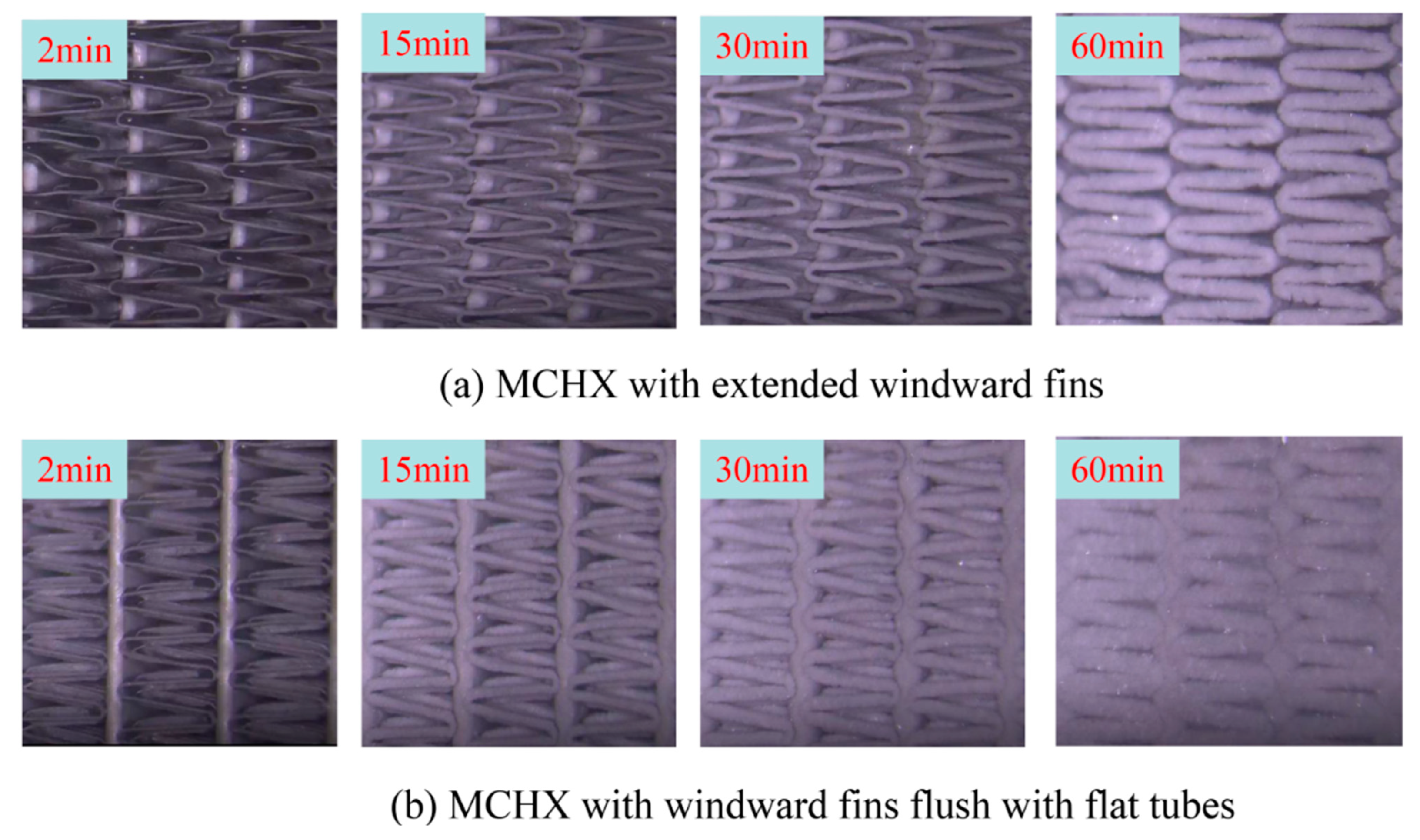
Figure 4.
Schematic diagram of frost layer distribution for two heat exchangers at different frosting stages.
Figure 4.
Schematic diagram of frost layer distribution for two heat exchangers at different frosting stages.
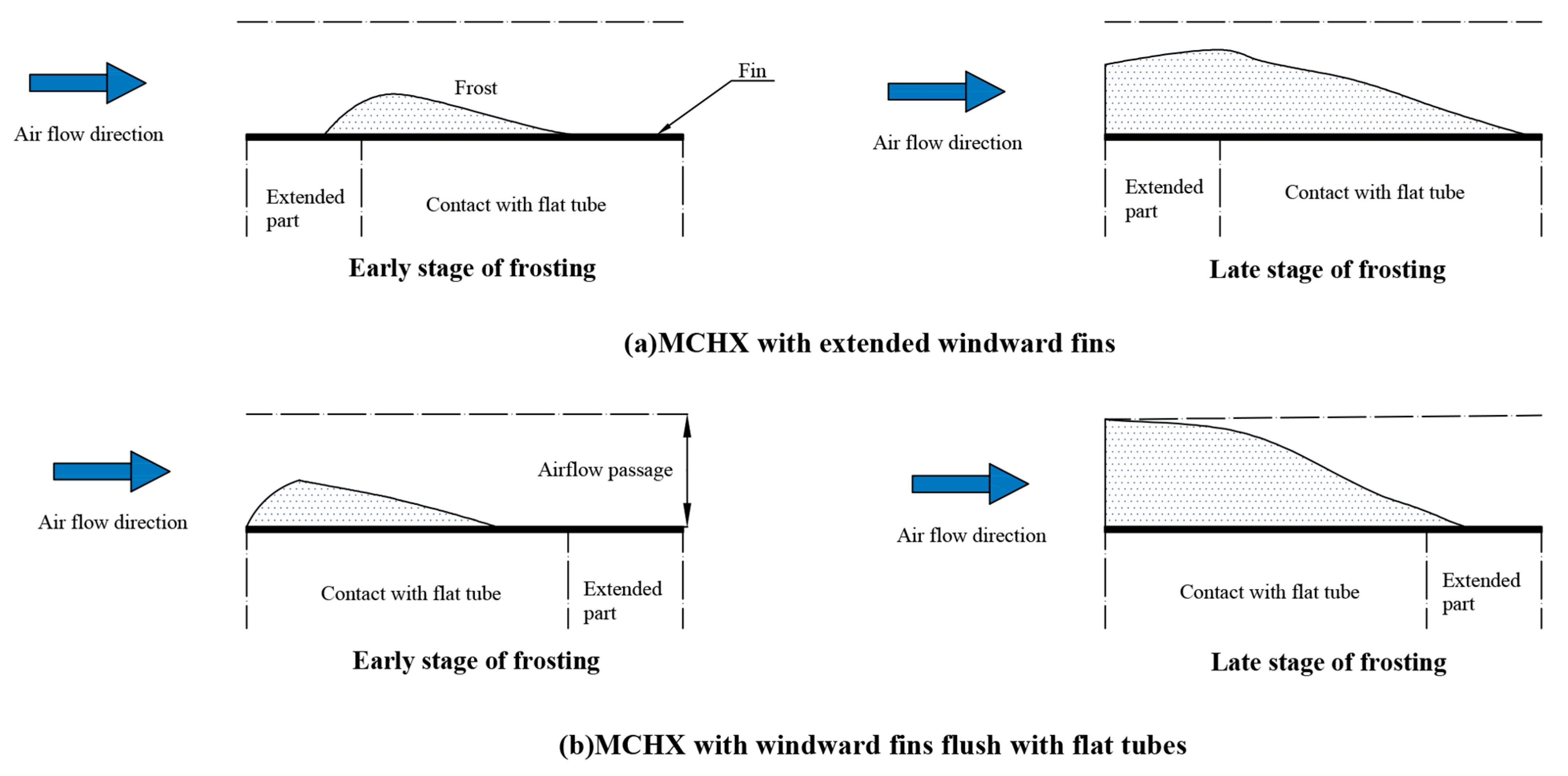
Figure 5.
The variation of heat transfer rate with time for different MCHXs under frosting conditions [(a) Tc,in = −10 °C, RH = 80%, (b) Tc,in = −10 °C, RH = 90%, (c) Tc,in = −7 °C, RH = 80%, (d) Tc,in = −7 °C, RH = 90%].
Figure 5.
The variation of heat transfer rate with time for different MCHXs under frosting conditions [(a) Tc,in = −10 °C, RH = 80%, (b) Tc,in = −10 °C, RH = 90%, (c) Tc,in = −7 °C, RH = 80%, (d) Tc,in = −7 °C, RH = 90%].
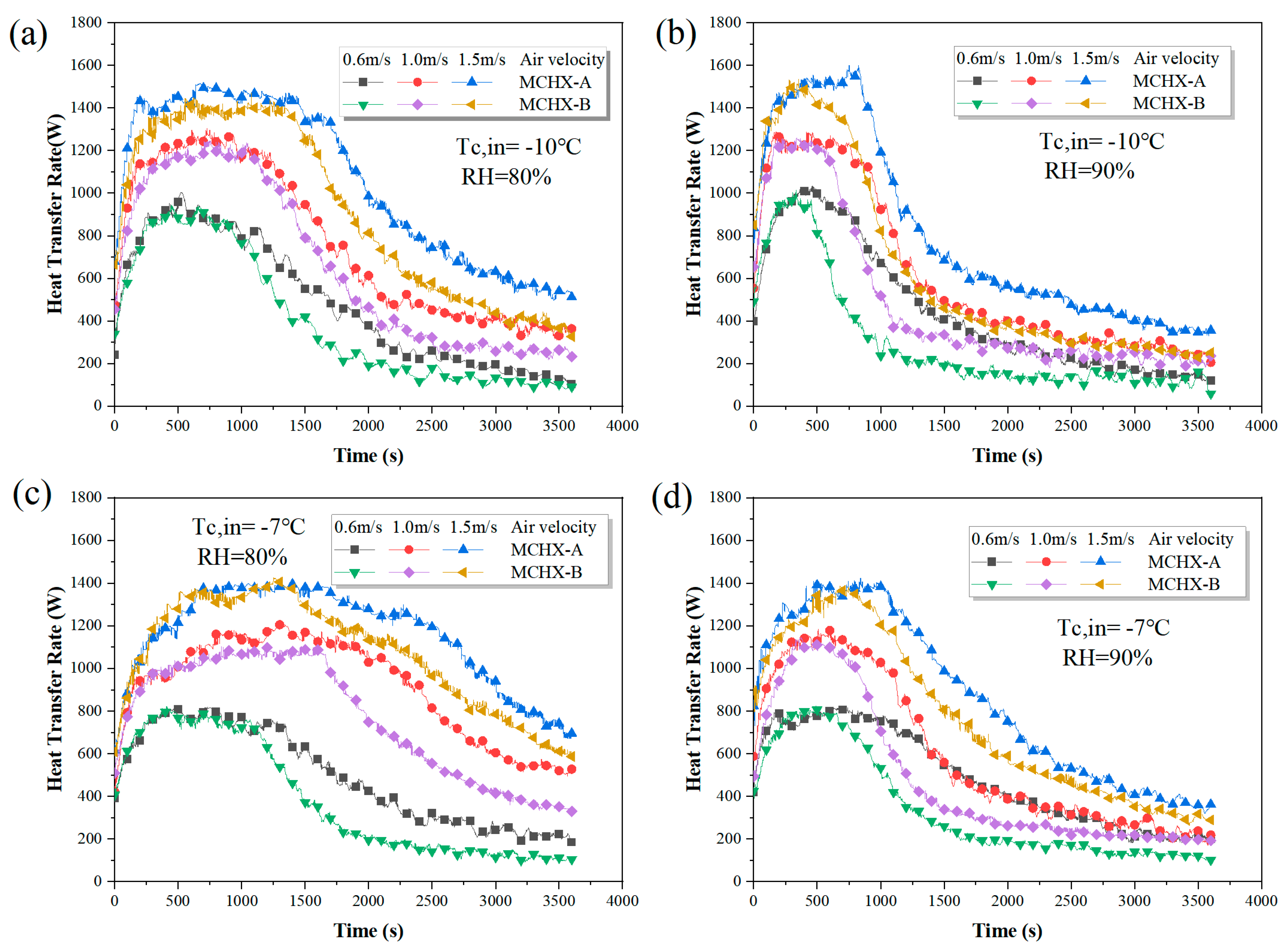
Figure 6.
The heat transfer capability for different MCHXs under frosting conditions [(a) Tc,in = −10 °C, RH = 80%, (b) Tc,in = −10 °C, RH = 90%, (c) Tc,in = −7 °C, RH = 80%, (d) Tc,in = −7 °C, RH = 90%].
Figure 6.
The heat transfer capability for different MCHXs under frosting conditions [(a) Tc,in = −10 °C, RH = 80%, (b) Tc,in = −10 °C, RH = 90%, (c) Tc,in = −7 °C, RH = 80%, (d) Tc,in = −7 °C, RH = 90%].
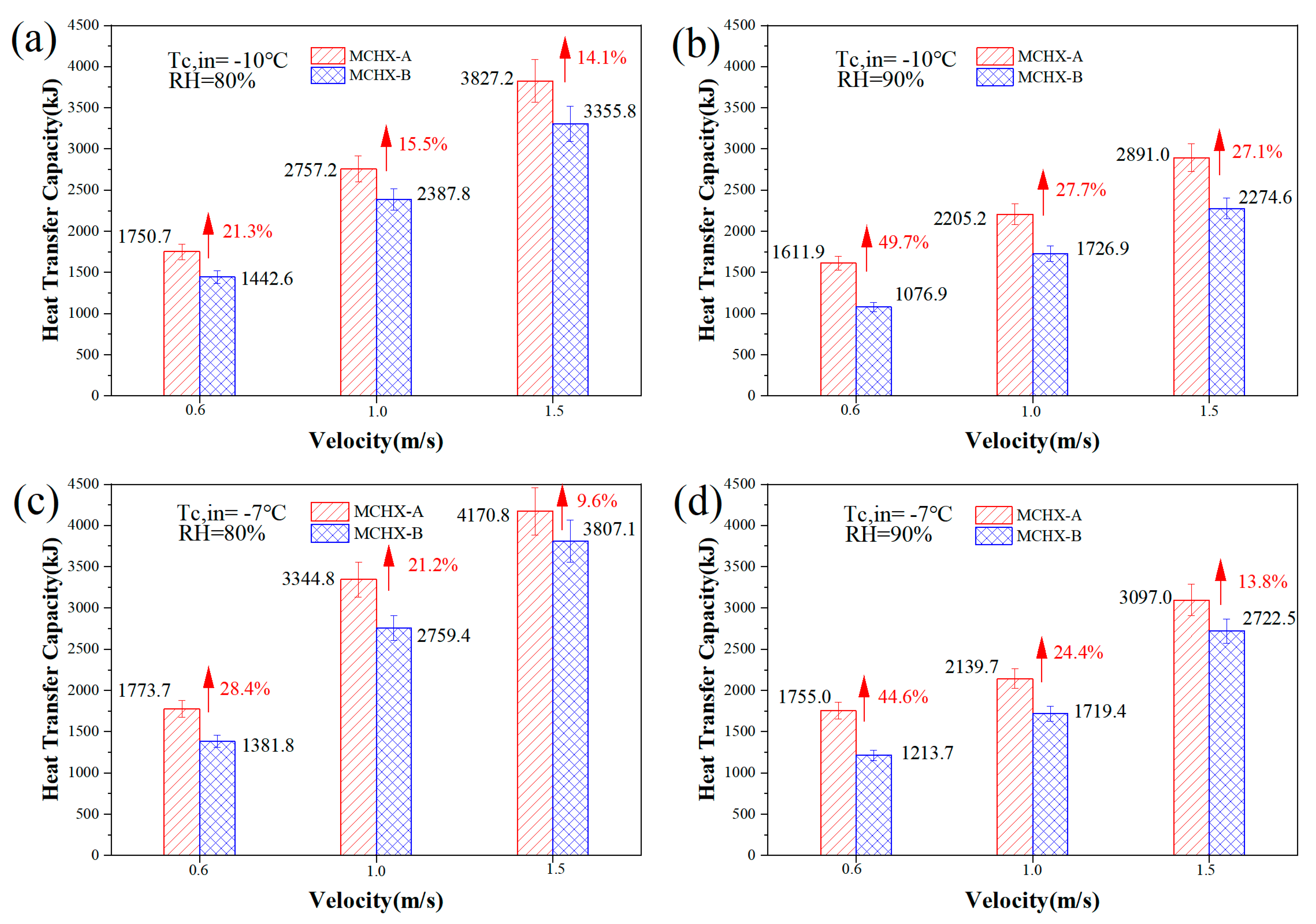
Figure 7.
The frost accumulation variation with time for different MCHXs under frosting conditions [(a) Tc,in = −10 °C, RH = 80%, (b) Tc,in = −10 °C, RH = 90%, (c) Tc,in = −7 °C, RH = 80%, (d) Tc,in = −7 °C, RH = 90%].
Figure 7.
The frost accumulation variation with time for different MCHXs under frosting conditions [(a) Tc,in = −10 °C, RH = 80%, (b) Tc,in = −10 °C, RH = 90%, (c) Tc,in = −7 °C, RH = 80%, (d) Tc,in = −7 °C, RH = 90%].

Figure 8.
Total frost accumulation on different MCHXs [(a) Tc,in = −10 °C, RH = 80%, (b) Tc,in = −10 °C, RH = 90%, (c) Tc,in = −7 °C, RH = 80%, (d) Tc,in = −7 °C, RH = 90%].
Figure 8.
Total frost accumulation on different MCHXs [(a) Tc,in = −10 °C, RH = 80%, (b) Tc,in = −10 °C, RH = 90%, (c) Tc,in = −7 °C, RH = 80%, (d) Tc,in = −7 °C, RH = 90%].
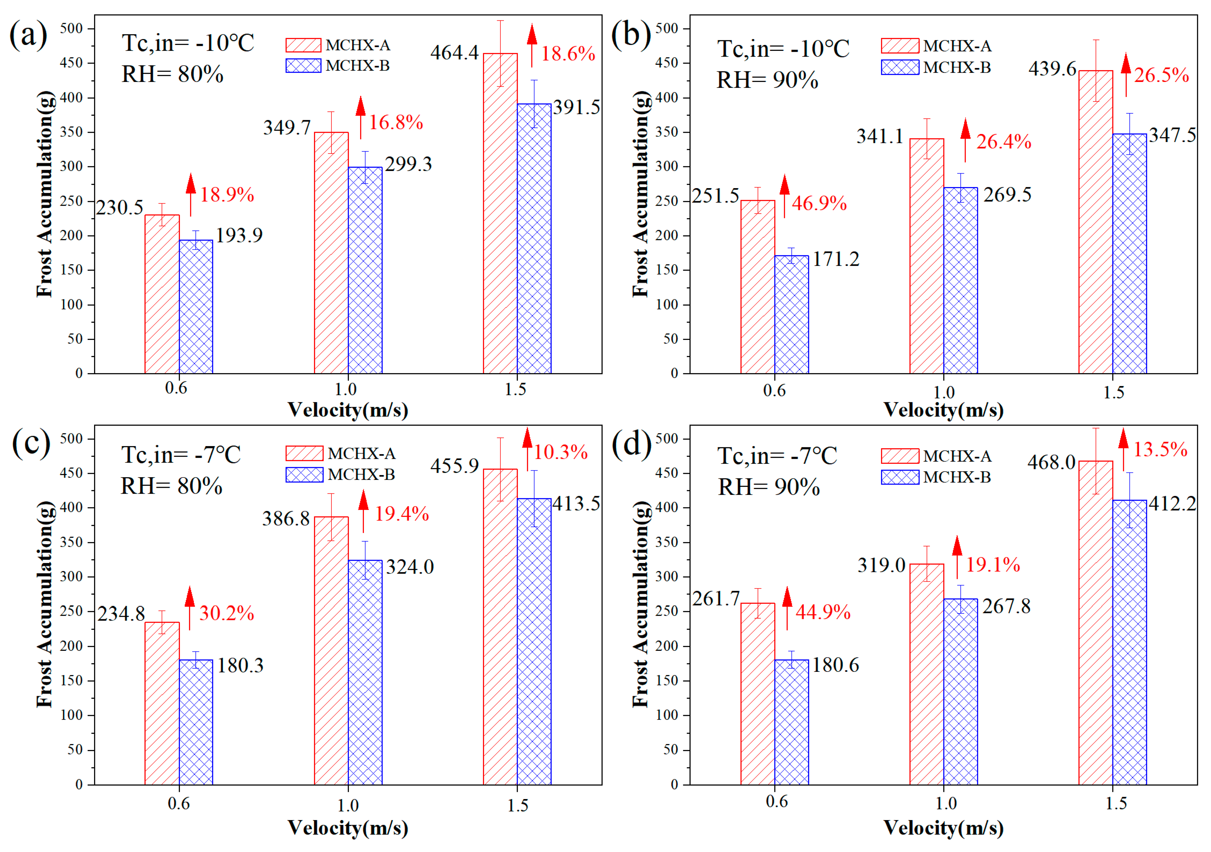
Figure 9.
Air-side pressure drop variation with time for different MCHXs under frosting conditions [(a) Tc,in = −10 °C, RH = 80%, (b) Tc,in = −10 °C,RH = 90%, (c) Tc,in = −7 °C, RH = 80%, (d) Tc,in = −7 °C, RH = 90%].
Figure 9.
Air-side pressure drop variation with time for different MCHXs under frosting conditions [(a) Tc,in = −10 °C, RH = 80%, (b) Tc,in = −10 °C,RH = 90%, (c) Tc,in = −7 °C, RH = 80%, (d) Tc,in = −7 °C, RH = 90%].

Table 1.
The MCHX structure parameters for two samples.
| Component | Specifications | |
|---|---|---|
| MCHX | Vertical height (H): 437 mm | Horizontal length (L): 408 mm |
| Fin height (S): 8.1 mm | Fin thickness: 0.1 mm | |
| Flat tube width (W): 20.6 mm | Louver angle (): 40° | |
| Louver pitch ():1.8 mm | Flat tube thickness: 1.3 mm | |
| Louver number: 10 | Fin pitch (): 1.7 mm | |
| Number of flat tubes: 34 Fin depth (): 25.4 mm | Extension length (P): 4 mm | |
Table 2.
Experimental conditions.
| Parameters | Range |
|---|---|
| Ambient air temperature | 2 °C |
| RH | 80% and 90% |
| Inlet coolant temperature | −7 °C and −10 °C |
| Frontal air velocity | 0.6 m/s, 1 m/s, and 1.5 m/s |
Table 3.
Specifications of the measurement instrument.
| Instrument Name | Rang | Accuracy |
|---|---|---|
| T type thermocouple | −200–350 °C | ±0.5 °C |
| Hot-wire anemometer | 0–99 | ±0.1 |
| Air pressure transmitter | 0–200 Pa | ±0.4 Pa |
| Air temperature sensor | −40–80 °C | ±0.5 °C |
| Humidity transmitter | 0%~100% RH | ±2% RH |
Table 4.
Relative uncertainties of typical parameters.
| Parameter | Relative Uncertainty |
|---|---|
| Pressure drops | ±0.4%–±1.3% |
| Frost formation rate | ±6.6%–±9.8% |
| Heat transfer rate | ±5.2%–±6.9% |
Disclaimer/Publisher’s Note: The statements, opinions and data contained in all publications are solely those of the individual author(s) and contributor(s) and not of MDPI and/or the editor(s). MDPI and/or the editor(s) disclaim responsibility for any injury to people or property resulting from any ideas, methods, instructions or products referred to in the content. |
© 2023 by the authors. Licensee MDPI, Basel, Switzerland. This article is an open access article distributed under the terms and conditions of the Creative Commons Attribution (CC BY) license (https://creativecommons.org/licenses/by/4.0/).
Share and Cite
MDPI and ACS Style
Xiong, T.; Liu, G.; Yan, G. Performance Improvement of Microchannel Heat Exchangers with Modified Louver Fins under Frosting Conditions. Appl. Sci. 2023, 13, 6378. https://doi.org/10.3390/app13116378
AMA Style
Xiong T, Liu G, Yan G. Performance Improvement of Microchannel Heat Exchangers with Modified Louver Fins under Frosting Conditions. Applied Sciences. 2023; 13(11):6378. https://doi.org/10.3390/app13116378
Chicago/Turabian StyleXiong, Tong, Guoqiang Liu, and Gang Yan. 2023. "Performance Improvement of Microchannel Heat Exchangers with Modified Louver Fins under Frosting Conditions" Applied Sciences 13, no. 11: 6378. https://doi.org/10.3390/app13116378
Note that from the first issue of 2016, this journal uses article numbers instead of page numbers. See further details here.