Article

The Fault Ride-Through Characteristics of a Double-Fed Induction Generator Using a Dynamic Voltage Restorer with Superconducting Magnetic Energy Storage

1
Electric Power Research Institute, State Grid Ningxia Electric Power Co., Ltd., Yinchuan 750011, China
2
Key Laboratory of Smart Grid of Ministry of Education, Tianjin University, Tianjin 300072, China
3
National Industry-Education Platform of Energy Storage, Tianjin University, Tianjin 300072, China
4
International Engineering Institute, Tianjin University, Tianjin 300072, China
*
Author to whom correspondence should be addressed.
Appl. Sci. 2023, 13(14), 8180; https://doi.org/10.3390/app13148180
Submission received: 19 May 2023 / Revised: 9 June 2023 / Accepted: 12 June 2023 / Published: 13 July 2023
(This article belongs to the Special Issue High-Temperature Superconductors and Their Applications)

Abstract

:
With the prevalence of renewable energy sources such as wind power in the power system, analyzing the fault characteristics of systems composed of DFIGs is becoming increasingly important. Therefore, this article analyzes, at first theoretically, the fault characteristics of a doubly fed induction generator (DFIG) during fault periods. It was found that the fault current of the DFIG exhibited the frequency offset phenomenon, which is affected by the depth of voltage dips and can negatively impact traditional distance protection. Furthermore, a method using a dynamic voltage restorer (DVR) based on superconducting magnetic energy storage (SMES) was adopted to compensate for the fault voltage of DFIG, which can mitigate the voltage dips of the DFIG. This method can not only achieve the fault ride through for DFIG but also significantly improve the frequency offset of the fault current during fault periods. Finally, a model composed of a 2.5 MW DFIG-based wind turbine and a 2.5 MW DVR-based SMES was built using a real-time digital simulator (RTDS) platform, and the simulation results showed that the fault stator voltage of DFIG can be compensated at a rated value of 0.69 kV, and the frequency of fault current can be maintained at 50 Hz These results validate the excellent performance of the method in achieving the fault ride through of DFIG and improving the frequency offset of the fault current by comparing multiple type faults while employing different protection methods.

1. Introduction

With issues regarding the energy crisis and climate degradation becoming increasingly prominent [1,2], developing renewable energy such as wind power has become a major demand for many countries to implement national energy security and low-carbon strategies [3,4]. For example, in order to cater to the augmenting energy needs, the government of India has established a target of installing 175 GW of renewable sources, which includes 65 GW of wind energy [5]. Additionally, the European Commission has taken the lead regarding energy targets by publishing the ambitious plan “A Clean Planet for All” and setting the target producing 300 GW of wind power by 2050 [6]. Due to wind power’s excellent characteristics, such as being cost-effective and the small capacity of the power converter used [7], DFIGs have been widely popular in wind power applications [8,9]. However, the stator winding of a DFIG is directly connected to the power grid [10], so it is easy for it to be affected by voltage fluctuations in the power grid [11,12].
Therefore, it is very challenging to assess how to complete the fault ride through of DFIG and reduce its negative impact on the power grid, and how to analyze the fault characteristics of DFIG during the faults. In [13], an asymmetrical fault ride-through control strategy was proposed by considering the voltage capacity limitation of a rotor side converter (RSC), and this strategy could fulfill the fault ride through of DFIG in an severe asymmetrical fault. In [14], an air-gap flux feedback control strategy was designed and applied to a VSG-controlled DFIG to accelerate the decay of transient components. When using this method, DFIG can behave like a synchronous generator and stabilize the voltage and frequency during faults. In [15], a scaled current tracking control was proposed for DFIG to enhance the low-voltage ride-through capacity without flux observation, which can suppress the overcurrent and overvoltage of DFIG rotor.
However, during severe faults, enhancing hardware measures need to be taken for fault ride through. In [16], an internal model control controller was proposed to improve the fault ride-through capabilities, which takes into account the power limitations of DFIG converters and the DC link voltage during the faults and consequent crowbar activation. In [17,18], the coordinated control of crowbar and chopper protection was considered to achieve the fault ride through of DFIG. In [19], the crowbar circuit was proposed to assist the RSC to improve fault response, which can divert the transient overcurrent of both fault initiation and clearance. In [20], the crowbar was utilized to suppress the rotor overcurrent and the releasing time of the crowbar was analyzed. In [21], an active crowbar circuit composed of silicon-controlled rectifiers was presented to achieve the fault ride through, and this design could strengthen the reliability of the circuit due to the high surge capability of silicon-controlled rectifiers. In [22,23], a novel protection scheme was proposed in which a superconducting fault current limiter is connected in series with the rotor winding of the DFIG or the DFIG outlet, which can effectively limit the maximum value of the fault rotor current or improve the fault voltage at the outlet of the DFIG. In [24], a modular multilevel converter was employed for the DFIG to suppress the fault current, which can provide the transient damping of the DFIG rotor and stator currents during severe grid faults to achieve the fault ride through. In [25], a modulated series dynamic braking resistor control strategy was presented to enhance the capacity of DFIG fault ride through. This scheme can offer fault voltage compensation and provide power evacuation to reduce the power imbalance during the fault periods.
Analyzing the fault characteristics of DFIGs during fault ride through is of great significance for power system protection. In [26], a time domain analysis was presented to elaborate on how the rotor current and voltage can be coordinated to ride through severe grid faults under the capacity limiting effect of RSC. In [27], a short-circuit fault analysis of a grid-connected DFIG based on a wind turbine was proposed by considering the active crowbar circuit protection for ride-through capability and power quality improvement.
Through the above literature review, it has been found that there is little research on analyzing and improving the frequency offset of the DFIG fault current while successfully completing the fault ride through of the DFIG. Therefore, this study first conducted a mathematical modeling of the DFIG and theoretically deduced the fault current expression of the DFIG. The accuracy of the theoretical fault current expression was verified through the fault current curve obtained through simulation. Through analysis, it can be found that during fault periods, the fault current of the DFIG exhibits a frequency offset phenomenon and can be affected by voltage dips in the crowbar circuit. Thus, during fault periods, a DVR-based SMES system was adopted to compensate for the fault voltage at the DFIG outlet, which can achieve the fault ride through of the DFIG and improve the frequency offset of the fault current by raising the fault voltage.
The rest of this article is organized as follows. Section 2 introduces the working principle of the DFIG-based wind turbine system and the model of the DFIG and theoretically derived expression of the DFIG fault current and the verification of the accuracy of the theory through simulation. Section 3 introduces the principle of the DVR-based SMES system, the VSC converter control strategy in DVR, and the DC/DC converter control strategy of SMES. In Section 4, extensive simulation results are provided to verify the performance of the adopted control method. Finally, the conclusion is given in Section 5.

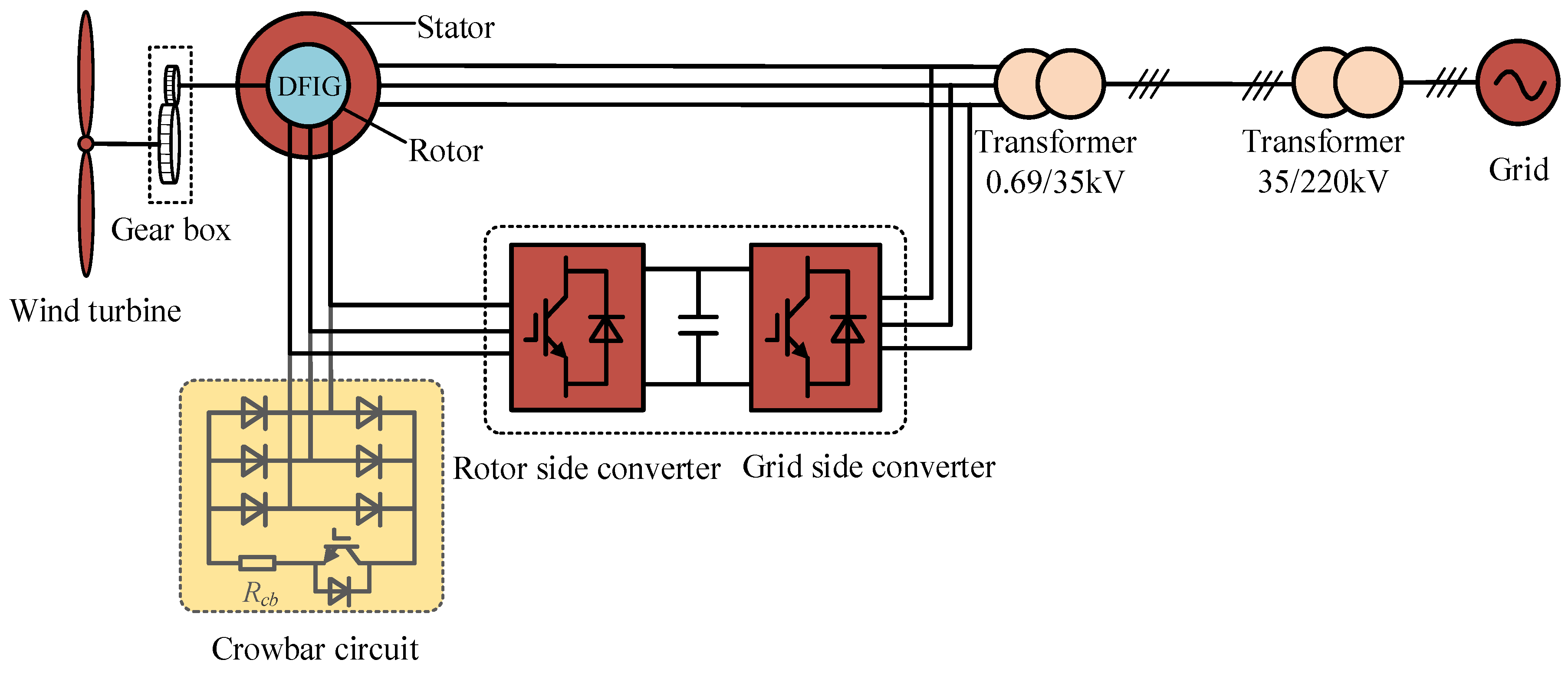
2. DFIG-Based Wind Turbine System

2.1. Working Principle of the DFIG-Based Wind Turbine System

The bidirectional back-to-back converter capacity of a DFIG is usually 20% to 30% of the wind turbine capacity, which is relatively low in cost compared to full-power wind turbines. Currently, this is the most widely used power generation model in the wind power field. The structure of the DFIG is shown in Figure 1, mainly including a wind turbine, a gear box, a DFIG, a back-to-back converter composed of a grid-side converter (GSC) and a rotor side converter, and a crowbar circuit. Among them, the wind turbine converts wind energy into kinetic energy, which can drive the DFIG to generate electrical energy. Additionally, the energy is transmitted to the power grid through stator and rotor windings [28]. The crowbar circuit can be activated in accordance with the fault current of the DFIG rotor during fault periods.

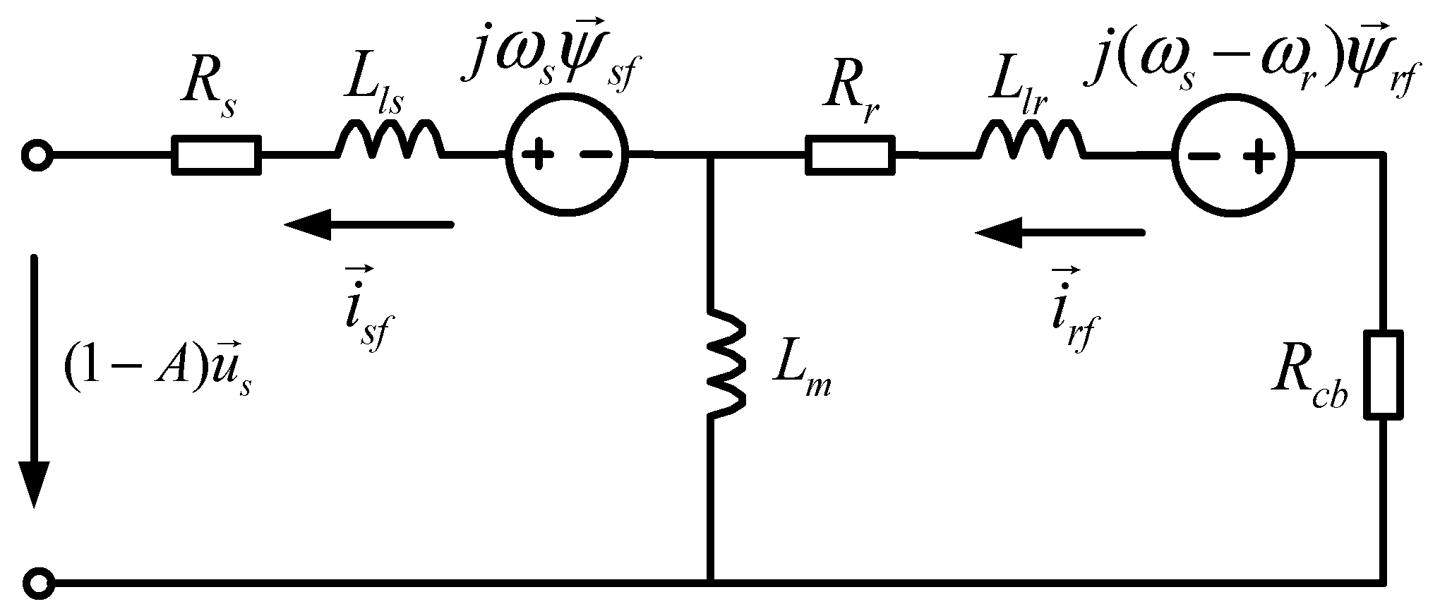
2.2. Modeling of the DFIG

In the study, the convention of generators was adopted to specify the positive direction of stator voltage and current; i.e., the positive current generates negative magnetic flux. The motor convention specifies the positive direction of the rotor voltage and current; i.e., the positive current generates a positive magnetic flux. Conventionally, through Park transformation, the three-phase windings on the stator and rotor sides of the DFIG in the a-b-c coordinate system are equivalent to mutually perpendicular two-phase windings in the d-q synchronous rotating reference frame, which can simplify the mathematical model of DFIG. Additionally, the magnetic circuit is fixed and there is no coupling between the magnetic flux.
In the d-q synchronous rotating reference frame, the voltage equation of the stator and rotor can be expressed as
u s d = R s i s d ω s ψ s q + D ψ s d u s q = R s i s q + ω s ψ s d + D ψ s q u r d = R r i s d ( ω s ω r ) ψ r q + D ψ r d u r q = R r i r q + ( ω s ω r ) ψ r d + D ψ r q ,
The flux equation of stator and rotor is as follows:
ψ s d = L s i s d + L m i r d ψ s q = L s i s q + L m i r q ψ r d = L m i s d + L r i r d ψ r q = L m i s q + L r i r q ,
where R s and R r are the resistance of stator and rotor winding, respectively; ω s and ω r are the synchronous speed and rotor speed; u s d , u s q , u r d , and u r q are the d-axis and q-axis components of the stator voltage and rotor voltage; i s d , i s q , i r d , and i r q are the d-axis and q-axis components of the stator voltage and rotor current; ψ s d , ψ s q , ψ r d , and ψ r q are the d-axis and q-axis components of the stator magnetic flux and rotor magnetic flux; L s and L r are the self-inductance of the stator and rotor windings; and L m is the mutual inductance between stator and rotor windings.
The active and reactive output power of the DFIG stator can be calculated as
P s = 3 2 ( u s d i s d + u s q i s q ) Q s = 3 2 ( u s q i s d u s d i s q ) ,
The active and reactive output power of the DFIG rotor can be expressed as
P r = 3 2 ( u r d i r d + u r q i r q ) Q r = 3 2 ( u r q i r d u r d i r q ) ,

2.3. Fault Characteristics of DFIG

2.3.1. Crowbar Circuit

When grid faults occur, the voltage dips of the DFIG terminal can cause sudden increases in stator and rotor current, which may cause DC link overvoltage of the DFIG and damage to the RSC of the converter. These damages can lead to the direct disconnection of the DFIG from the grid [27,29,30].
Thus, in the event of grid faults, the crowbar circuit is usually applied to suppress the rotor overcurrent of the DFIG and protect the RSC of the DFIG from the negative influence of rotor overcurrent. As shown in Figure 1, the crowbar circuit is composed of a diode rectifier circuit, an IGBT, and a crowbar resistor. Additionally, the working principle of a crowbar circuit is that when the rotor overcurrent of the DFIG is larger than 2 pu, the crowbar circuit will be activated by a gate signal from the IGBT. During the activation of the crowbar circuit, the fault overcurrent of the rotor will be limited by the crowbar resistance, which can avoid the rotor overcurrent from damaging the RSC of the DFIG. When the fault is cleared, the crowbar circuit is deactivated.
Therefore, it is particularly important to analyze the fault characteristics of the DFIG when the crowbar circuit is activated during grid faults.

2.3.2. Fault Current of the DFIG

Assuming a fault voltage dip occurs in the DFIG at t = 0, the DFIG terminal voltage during the fault is
u 1 = ( 1 A ) U s e j ( ω s t + θ ) ,
where A is the depth of the DFIG voltage dips; U s is the amplitude of the DFIG terminal voltage before the fault; and θ is the phase of the DFIG terminal voltage at 0 s.
Considering that the stator flux cannot suddenly change when the fault occurs, and neglecting the stator resistance, the stator flux during fault periods can be obtained from Equation (1):
ψ s = A U s j ω s e t / T s + j θ + ( 1 A ) U s j ω s e j ( ω s t + θ ) ,
where T s = L s / R s , L s = L s L m 2 / L r ; T s is the decay time constant of the stator circuit; and L s is the transient reactance of the DFIG stator.
Assuming that the crowbar circuit is instantaneously activated when the fault occurs, and the equivalent circuit to the DFIG with the crowbar circuit in a d-q synchronous rotating reference frame is shown in Figure 2. Thus, after the fault, the voltage equation and flux equation can be obtained as follows:
( 1 A ) u s = R s i s f + D ψ s f + j ω s ψ s f 0   =   ( R r + R c b ) i r f + D ψ r f + j ( ω s ω r ) ψ r f ψ s f = L s i s f + L m i r f ψ r f = L m i s f + L r i r f ,
where R c b is the crowbar resistance; i s f and i r f are the steady-state currents of the DFIG stator and rotor after the fault; and ψ s f and ψ r f are the steady-state flux of the DFIG stator and rotor after the fault. In the d-q synchronous rotating reference frame, D ψ r f = 0. Additionally, the DFIG rotor’s steady-state flux can be calculated using Equation (7):
ψ r f = f ( s , R c b ) ψ s f = f ( s , R c b ) ( 1 A ) U s j ω s e j ( ω s t + θ ) ,
f ( s , R c b ) = ( R r + R c b ) L m [ ( R r + R c b ) + j ( ω s ω r ) L r ] L s ,
where L r = L r L m 2 / L s , which represents the transient reactance of the DFIG rotor. Considering that the rotor flux cannot suddenly change at the time of the fault, the flux of the DFIG rotor can be expressed as
ψ r = [ ψ r 0 e j ( α + θ ) f ( s , R c b ) ( 1 A ) U s j ω s e j θ ] e t / T r + j ω r t + f ( s , R c b ) ( 1 A ) U s j ω s e j ( ω s t + θ ) ,
where T r = L r / ( R r + R c b ) , which represents the decay time constant of the rotor circuit. ψ r 0 is the rotor flux before the fault. Combining Equations (2), (3), and (5), the rotor flux after the fault can be obtained as follows:
ψ r 0 = ( L s L r L m 2 ) 2 Q s 3 L m U s + U s L r ω s L m + j ( L s L r L m 2 ) 2 P s 3 L m U s ,
By substituting Equations (6) and (10) into Equation (2), the fault current i s of the DFIG stator can be expressed as
i s = A U s j ω s L s e t / T s + j θ + [ L m L r f ( s , R c b ) 1 ] ( 1 A ) U s j ω s L s e j ( ω s t + θ ) + L m L s L r [ ψ r 0 f ( s , R c b ) ( 1 A ) U s j ω s e j θ ] e t / T r + j ω r t ,
It can be seen in Equation (12) that the fault current of the DFIG stator consists of three parts: a DC component with the decay time constant of T s , a frequency component of ω s , and a frequency component of ω r with a decay time constant of T r . Additionally, the frequency of the fault stator current is influenced by the components of the three different frequency currents. Additionally, the three different frequency currents are determined by the depth of the voltage dips, the resistance of the crowbar circuit, the rotor speed, and so on.
When the fault voltage of the DFIG stator dips to 0 pu, the rotor speed of the DFIG is set to be 1.2 pu, and the resistance of the crowbar circuit is set to be 0.001 ohms. Additionally, in this situation, the fault current of the DFIG stator can be obtained through simulation, as shown in Figure 3. The simulation result is consistent with the theoretical curve, which verifies the accuracy of the theoretical analysis. Additionally, it can be found in Figure 3 that the frequency of the fault current clearly shifted from 50 Hz to 60 Hz. Thus, during the fault period, the fault current of the DFIG had the characteristics of frequency offset.

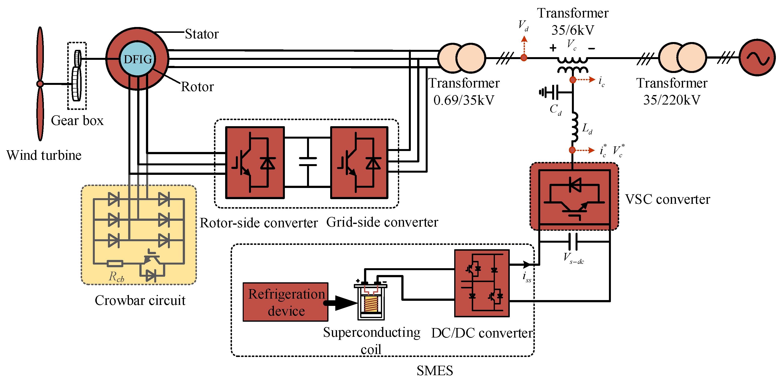
3. DFIG System with DVR-Based SMES

The DVR can assist the DFIG in achieving the fault ride through by compensating the voltage dips at the outlet of the DFIG. Additionally, raising the fault voltage at the DFIG outlet during the fault can also improve the frequency offset of the fault current, which can significantly impact the distance protection of the power systems. The DVR-based SMES mainly consists of a VSC converter and a SMES system composed of a DC/DC converter, superconducting coil, and a refrigeration device [31,32], as shown in Figure 4.
During a period of normal operation, the DVR-based SMES cannot compensate for the voltage of the 35 kV line. Additionally, there is no power exchange between the DVR-based SMES system and the power system. During a period where voltage dips occur, the DVR-based SMES system, in series with the 35 kV line, starts to compensate for the voltage dips, so that the voltage of the DFIG can resume at a normal value. Additionally, the method can mitigate the frequency offset of the fault current by increasing the fault voltage at the DFIG outlet.

3.1. Control Strategy of the VSC Converter

The controllable reference signals of the VSC converter of the DVR are V d d and V d q under the d-q rotating reference frame. V d d * and V d q * are the normal voltages of the 35 kV line before the faults. To accurately control the output voltage, the LC filter was considered to add into the d-q control loops.
Assuming the switching of the VSC converter in Figure 4 are all ideal switches, the mathematical model of the VSC converter in the three-phase stationary coordinate system can be expressed as
V c a = L d d i c a * d t + V c a * V c b = L d d i c b * d t + V c b * V c c = L d d i c c * d t + V c c * ,
where V c a , V c b and V c c are the compensated voltages in the 35 kV line; V c a * , V c b * and V c c * are the output voltages of the VSC converter; i c a * , i c b * and i c c * are the output currents of the VSC converter; and L d is the inductance of the LC filter.
In the d-q rotating reference frame, the mathematical equation of the VSC converter can be obtained by
V c d = L d d i c d * d t + V c d * ω s L d i c q V c q = L d d i c q * d t + V c q * + ω s L d i c d ,
where V c d and V c q are the compensated voltages in d-q rotating reference frame; V c d * , and V c q * , i c d * , and i c q * are output voltages and currents of the VSC converter in the d-q rotating reference frame. Additionally, considering the LC filter, i c d * and i c q * can be calculated as
i c d * = i c d ω s C d V c q i c q * = i c q + ω s C d V c d ,
By introducing Equation (1) into Equation (2), the following equation can be obtained:
V c d * = L d d d t ( i c d ω s C d V c q ) + ω s L d i c q * + V c d V c q * = L d d d t ( i c q + ω s C d V c d ) ω s L d i c d * + V c q ,
Additionally, using the above derivation, the control strategy of the converter can be obtained, as shown in Figure 5.

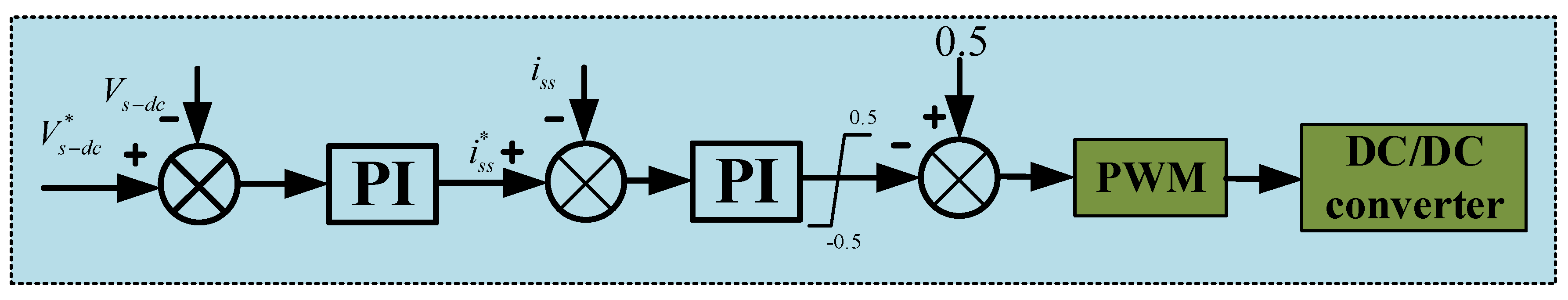
3.2. The Control Strategy of the DC/DC Converter

The function of the DC/DC converter is to stabilize the DC voltage by controlling the charging and discharging of the SMES. The control strategy is shown in Figure 6. The reference signal i s s * of the SMES output current is obtained by comparing the actual DC voltage V s d c and the reference voltage V s d c * . The output duty cycle of the DC/DC converter is 0 < D < 1 .

4. Simulation and Analysis

To evaluate the effectiveness of the adopted control strategy for achieving the fault ride through of the DFIG and improving the frequency offset of the fault current, a detailed simulation model of the topology shown in Figure 1 was built using the RTDS platform. The RTDS, developed and manufactured by the RTDS Corporation in Manitoba, Canada, is a device specifically designed to study electromagnetic transient phenomena in power systems. Version 1.4.0 of software RSCAD was adopted, and the simulation was performed using a discrete sampling period. The adopted simulation sampling time step of software was 50 µs. As shown in Figure 7, the simulated model of the DFIG with a DVR-based SMES system was first established on the principal computer, and the principal computer communicated with the hardware RTDS via an optical fiber. When the whole simulation system started to run, the simulation data in the principal computer was transferred to the RTDS through the optical fiber for calculation, and the RTDS transferred the calculation results to the principal computer through the optical fiber to obtain the simulation results. The specific parameters of the simulation model are shown in Table 1 and Table 2. Additionally, the PI parameters of the VSC converter control in the DVR are shown in Table 3.
The performance of the DVR-based SMES in achieving fault ride through and improving the frequency offset of fault current were verified under the multiple-type faults as follows.

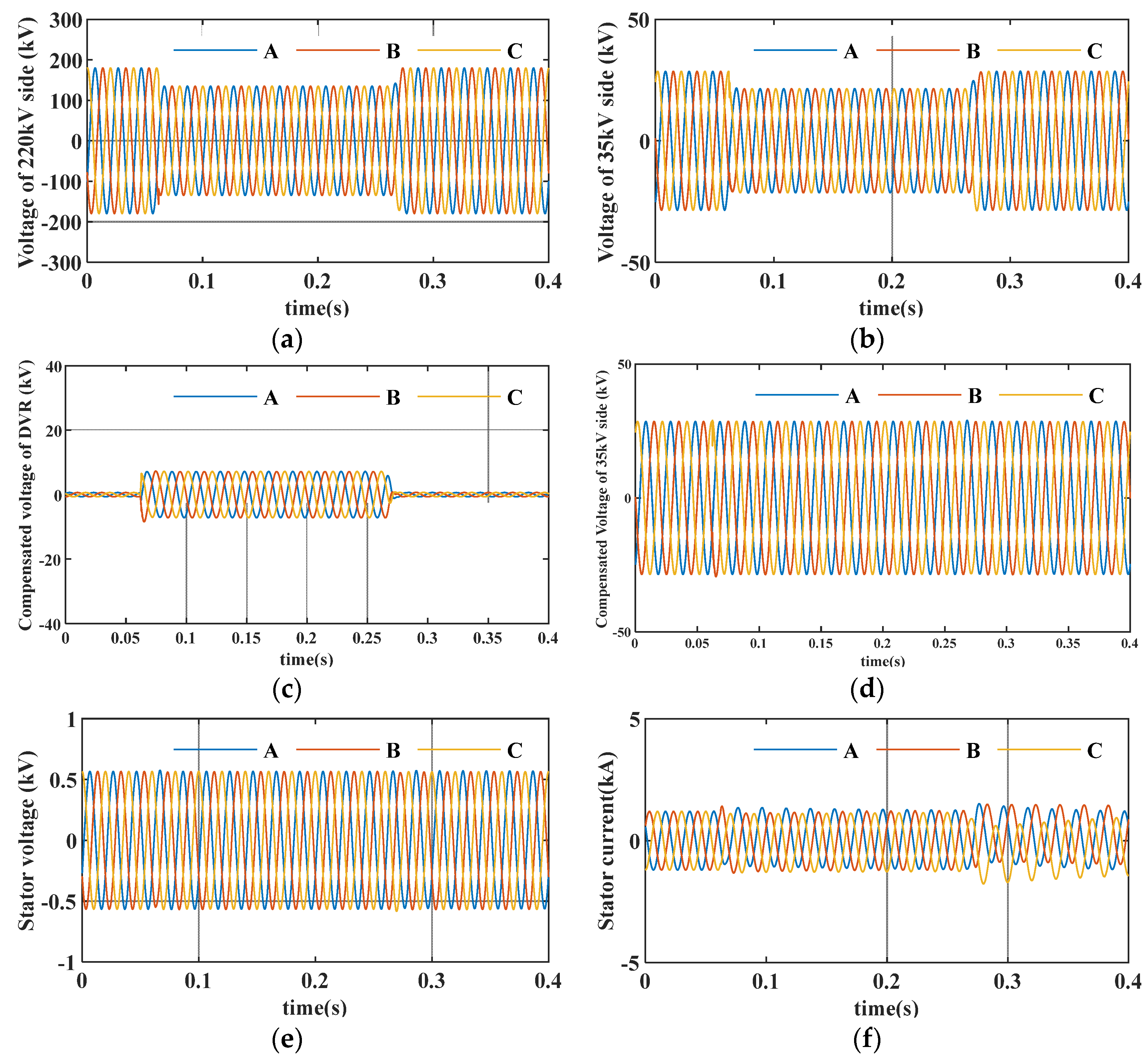
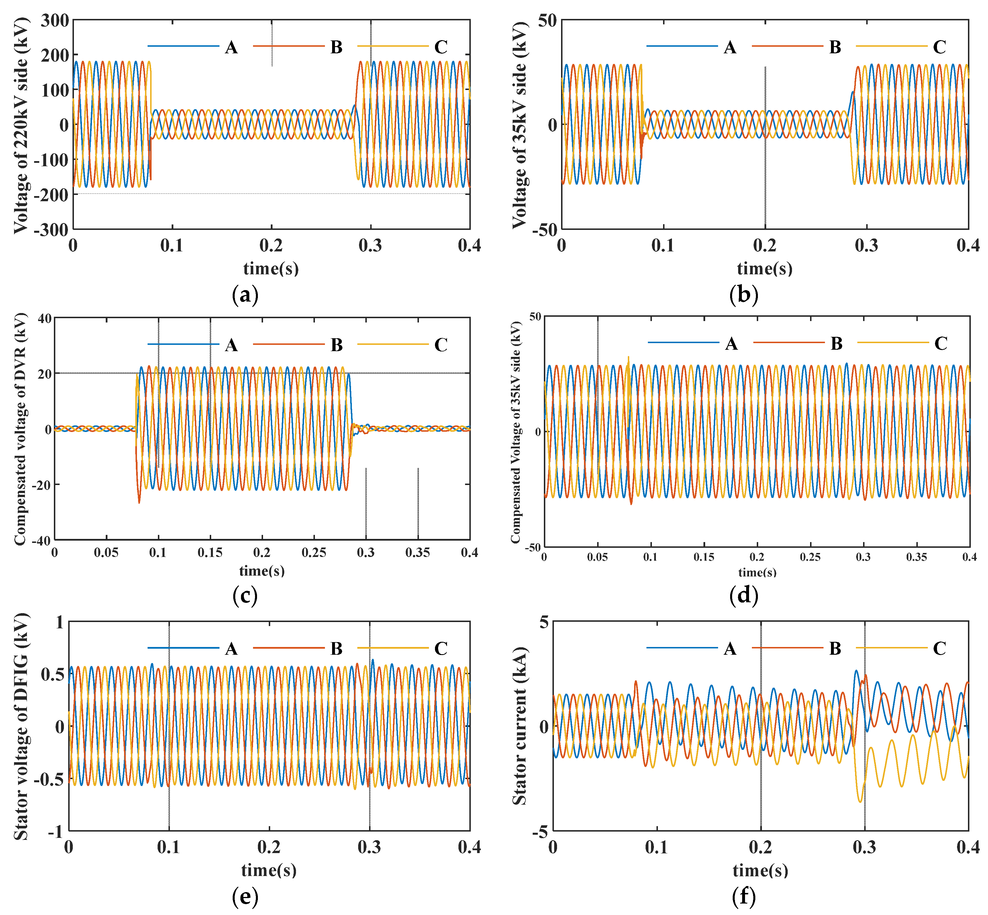
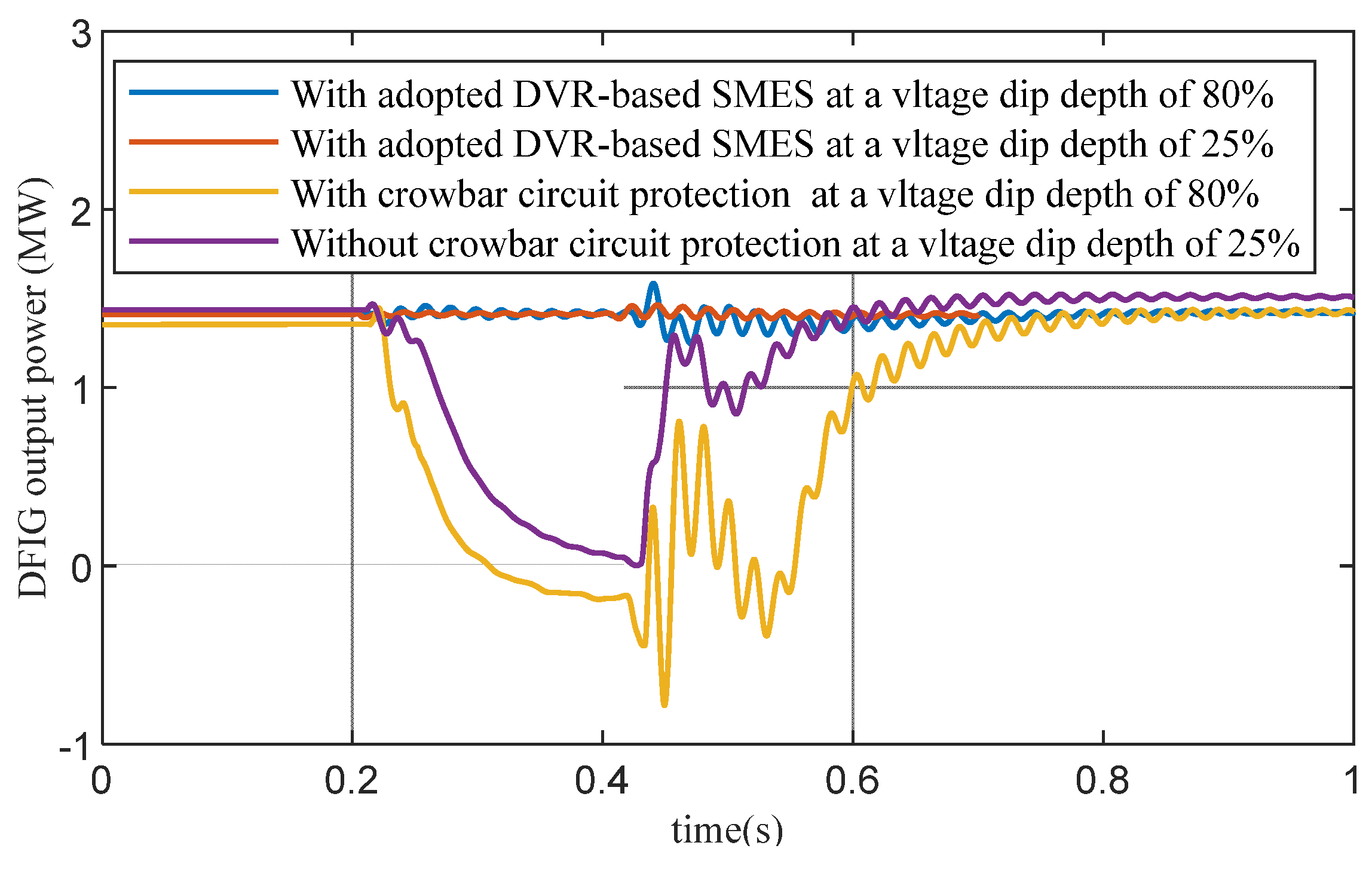
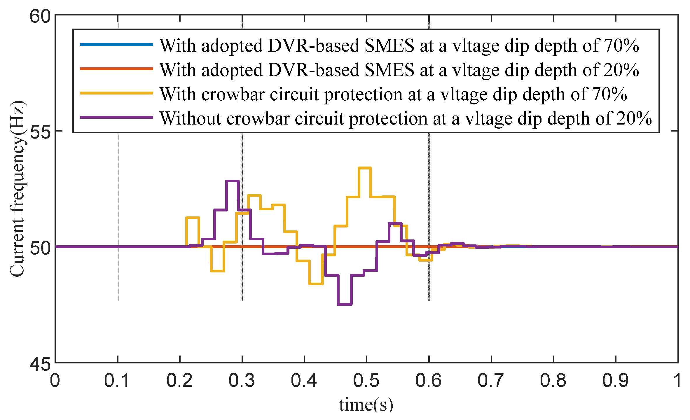
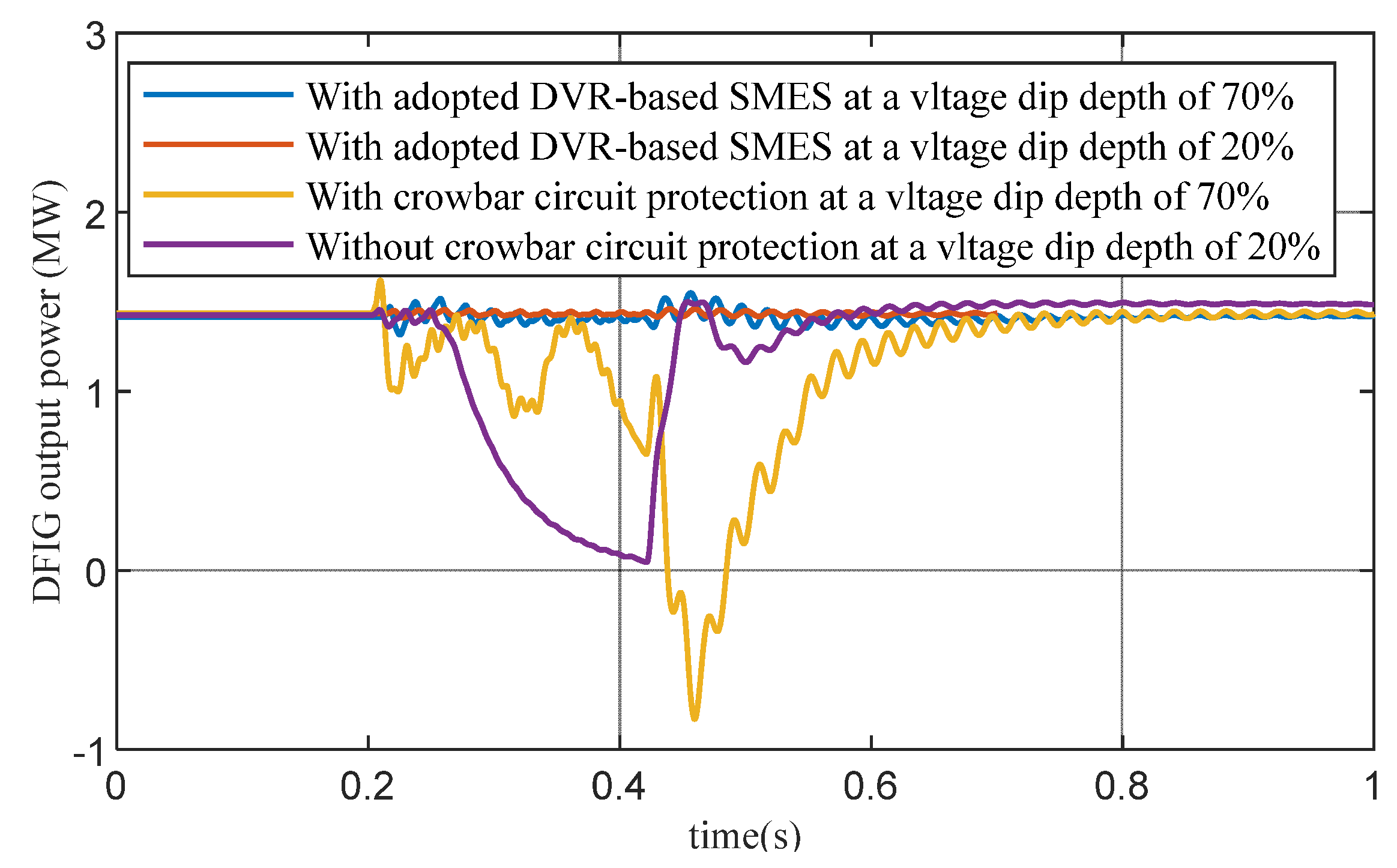
4.1. Three-Phase-to-Ground Fault

The performance of the DVR-based SMES in achieving the fault ride through of DFIG and improving the frequency offset of the fault current was first analyzed during a three-phase-to-ground symmetrical fault. As shown in Figure 8a, the three-phase-to-ground fault occurred in the 220 kV line near the DFIG at t = 0.08 s and was cleared at t = 0.28 s. The dip depth of three-phase fault voltage in the 220 kV line was 25%, the wind speed was set to 10 m/s, and the rotor speed of the DFIG is 1.12 pu.
The voltage of the 35 kV line was affected by the voltage dips of the 220 kV line; thus, the phenomenon of voltage dips also occurred in the 35 kV line, as shown in Figure 8b. At this time, the voltage dips in the 35 kV line could be detected by the DVR, and the voltage dips could be compensated by controlling the VSC converter of the DVR, so that the fault voltage in the 35 kV line could resume at the normal value 35 kV. During the fault period, the voltage provided by the DVR of the 35 kV line is shown in Figure 8c. Figure 8d shows the voltage of the 35 kV line after the DVR compensates. It can be seen in Figure 8d that the fault voltage of the 35 kV line can return to the voltage state before the fault. Figure 8e shows the stator voltage of the DFIG after the DVR compensates. It can be observed that during the fault period, the stator voltage of the DFIG experienced no severe fluctuations after the DVR compensated. During the fault period, the DVR system ensures that the stator voltage of the DFIG is no longer affected by the fault, which can improve the stability of the DFIG during the fault period. Figure 8f shows the stator current of the DFIG, and it can be observed that the stator current value of the DFIG could not reach the overcurrent value of 2 pu that would have triggered the crowbar circuit, which can enhance the stability of system.
Figure 9 shows the system’s responses with an adopted DVR-based SMES during a three-phase-to-ground fault (depth of 80%). Figure 9a shows the voltage condition in the 220 kV line when a three-phase-to-ground fault occurred in 220 kV line side, away from the DFIG, at t = 0.08 s, and the fault was cleared at t = 0.28 s. The dip depth of three-phase fault voltage in the 220 kV line was 80%. It can be seen in Figure 9b–d that the fault voltage in the 35 kV line can be compensated to a normal voltage value by the DVR-based SMES. Figure 9e shows that the stator voltage of the DFIG can be affected by the fault in the 220 kV line. Additionally, Figure 9f shows that the fault stator current of the DFIG cannot occur in the overcurrent during the fault period.
Additionally, it can be concluded from Section 2.3 that during fault periods, the frequency of the fault current is affected by the voltage dips and the crowbar circuit. Therefore, during the fault period, when the voltage of the 35 kV line is compensated by DVR system, the stator voltage of the DFIG can be less affected by the fault. Theoretically, during fault periods, the DVR-based SMES compensating for the fault voltage not only achieves the fault ride through of the DFIG, but also mitigates the frequency offset of the fault current of the DFIG.
Therefore, Figure 10 shows a comparison of the frequency of the fault current with a DVR-based SMES and with a conventional crowbar circuit protection at the different voltage dip depths. The two faults occurred at around t = 0.22 s and their duration was 0.2 s. It can be observed that the frequency of the fault current with the crowbar circuit protection not only fluctuated during the fault period, but also continued to fluctuate for a short period of time after the fault was cleared. This is because during fault periods, the rotor overcurrent caused by the voltage dips can result in the crowbar circuit being activated. However, the stator voltage of the DFIG was still in a severe dip, so there was still a serious frequency offset in the fault current. Additionally, after the fault is cleared, due to the withdrawal of the crowbar circuit, the system voltage and current will fluctuate again. Thus, the frequency of the fault current still existed after the fault was cleared.
Figure 11 shows a comparison of the DFIG output power when using an adopted DVR-based SMES at a voltage dip depth of 80%; an adopted DVR-based SMES at a voltage dip depth of 25%; crowbar circuit protection at a voltage dip depth of 80%; and crowbar circuit protection at a voltage dip depth of 25% when the three-phase-to-ground fault occurs. By comparing the crowbar circuit protection at voltage dip depths of 80% and 25%, it can be seen that when the DVR-based SMES is adopted to compensate for the fault voltage, the DFIG output power is mostly maintained in the normal output state.
To sum up, with DVR-based SMES to compensate the fault voltage of 35 kV line, the DVR-based SMES can isolate the DFIG from the 80% and 20% depth of three-phase-to-ground faults. Thus, it can prevent the voltage of DFIG from being affected by the faults. Moreover, the crowbar circuit cannot be activated during fault periods, so the frequency offset of the fault current is almost non-existent and can be maintained at 50 Hz. Additionally, the DFIG can output the normal power during the faults.

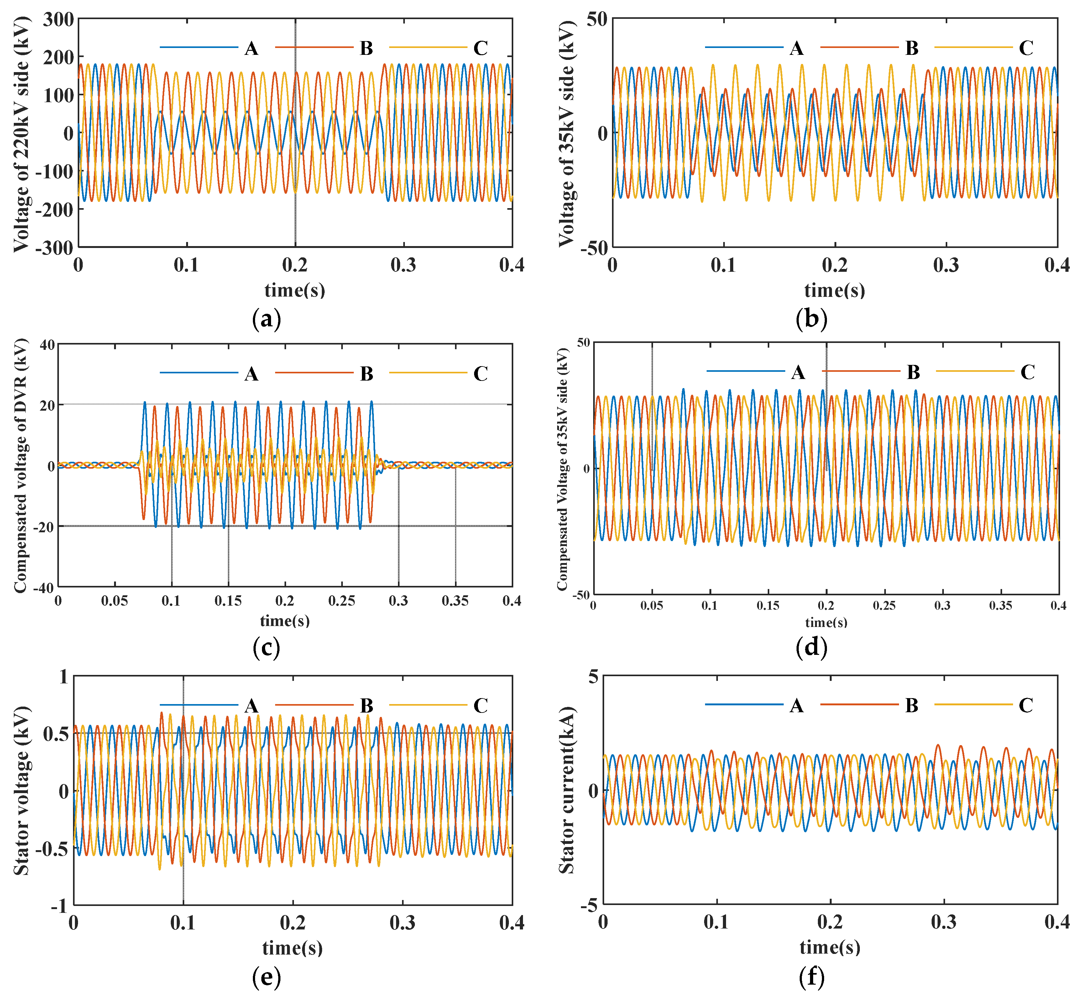
4.2. Single Phase-to-Ground Fault

In the power system, single phase-to-ground faults are the most commonly occurring. Therefore, this section verifies the performance of the adopted method in the case of single phase-to-ground faults. As shown in Figure 12a, the single phase-to-ground fault occurred in the 220 kV line near the DFIG at t = 0.075 s and was cleared at t = 0.275 s. Additionally, the depth of the single-phase voltage dip was 20% in the 220 kV line. The voltage of the 35 kV line is shown in Figure 12b. Due to the wiring method of the transformer, the two-phase voltage of the 35 kV line exhibited voltage dips. The voltage provided by the DVR of the 35 kV line during the fault period is shown in Figure 12c. Figure 12d shows the voltage of the 35 kV line after the DVR compensated. It can be seen in Figure 12d that the fault voltage of the 35 kV line can return to the voltage state before the single phase-to-ground fault. Figure 12e shows the stator voltage of the DFIG after the DVR compensated. It can be observed that during the fault period, the stator voltage of the DFIG exhibited no severe fluctuations after the DVR compensated. Figure 12f shows the stator current of the DFIG.
Figure 13 shows the system’s responses with a DVR-based SMES during the single phase-to-ground fault (depth of 70%). Additionally, the single phase-to-ground fault occurred in the 220 kV line, away from the DFIG, at t = 0.075 s and was cleared at t = 0.275 s. Additionally, the depth of the single-phase voltage dip was 70% in the 220 kV line, as shown in Figure 13a. Figure 13b–d shows the fault voltages on the 35 kV side, the compensating voltage of the DVR-based SMES, and the compensated fault voltages of the 35 kV side. It can be seen that the fault voltage of the 35 kV line can be compensated to return to the normal voltage value of 35 kV. Figure 12e shows the stator voltage of the DFIG after the DVR compensates. It can be observed that during the single-phase fault periods, the stator voltage of the DFIG exhibited no severe fluctuations. Figure 12f shows the stator current of the DFIG during the fault.
Figure 14 shows a comparison of the frequency of the fault current with a DVR-based SMES and with conventional crowbar circuit protection when the two different single phase-to-ground faults occur. The two single phase-to-ground faults occurred at 0.22 s, and the fault duration was 0.2 s. It can be seen from Figure 14 that the DVR-based SMES compensated for the fault voltage, and the fluctuations in the current frequency were less than the current frequency with conventional crowbar circuit protection. Therefore, during the single phase-to-ground faults, the DVR-based SMES can also assist the DFIG in achieving the fault ride through and improving the frequency offset of fault currents.
Figure 15 shows a comparison of the DFIG output power with an adopted DVR-based SMES at a voltage dip depth of 70%; an adopted DVR-based SMES at a voltage dip depth of 20%; crowbar circuit protection at a voltage dip depth of 70%; and crowbar circuit protection at a voltage dip depth of 20% when the single phase-to-ground fault occurs. With the DVR-based SMES at voltage dip depths of 70% and 20%, the DFIG output power was mostly maintained in the normal output state, which can be seen by comparing this with the crowbar circuit protection at voltage dip depths of 70% and 20%.
To sum up, during single phase-to-ground faults with voltage dip depths of 70% and 20%, the DVR-based SMES can improve the frequency of the fault current by compensating for the fault voltage. Additionally, the frequency of the fault current, which fluctuates between 42–53 Hz with crowbar circuit protection, can be maintained at 50 Hz with DVR-based SMES protection. Additionally, adopting DVR-based SMES to assist the DFIG in achieving the fault ride through during single phase-to-ground faults with voltage dip depths of 70% and 20%, the DFIG can output power at a normal value.

5. Conclusions

In this study, the working principle of the DFIG system was introduced, and the fault current characteristics of the DFIG were theoretically analyzed. The correctness of the theoretical calculations for the fault current of the DFIG stator was verified through the simulation results. Furthermore, it can be concluded that during the fault period, the fault current of the DFIG stator exhibits frequency offsetting, and the frequency offset of the fault current is closely related to factors such as the depth of the voltage dips and the crowbar circuit. Therefore, by adopting a DVR-based SMES system to compensate for the voltage dips of the DFIG in practical applications, the stator voltage of the DFIG can be compensated to a rated voltage of 0.69 kV, and the frequency offset of the fault current can be significantly improved to a rated frequency of 50 Hz. The simulation results using the RTDS platform show that during different-type faults, the DVR-based SMES can effectively compensate for the fault voltage of the 35 kV line. Additionally, during an 80% depth three-phase-to-ground fault, the frequency of the fault current, which fluctuates between 46–54 Hz, can be stabilized at 50 Hz. During a 70% depth single phase-to-ground fault, the frequency of the fault current, which fluctuates between 47–53 Hz, can be stabilized at 50 Hz. Additionally, with a DVR-based SMES to compensate for the fault voltage, the output power of the DFIG can be maintained at a normal power value during the fault. Therefore, this method can achieve the fault ride through and improve the frequency of the DFIG fault current. Additionally, future research should focus on how to reduce the cost of the DVR-based SMES device by making full use of DVR-based SMES or improving the design of the DVR-based SMES device.

Author Contributions

Conceptualization, methodology, investigation, formal analysis, L.L.; methodology, investigation, formal analysis, Y.L.; conceptualization, methodology, formal analysis, J.N.; conceptualization, methodology, investigation, J.H.; conceptualization, methodology, investigation, H.L.; investigation, formal analysis, supervision, B.L.; investigation, formal analysis, writing—review and editing, supervision, C.L.; methodology, visualization, writing—original draft preparation, writing—review and editing, Y.C. All authors have read and agreed to the published version of the manuscript.

Funding

This research was funded in part by the Science and Technology Research Program of the State Grid Ningxia Company. (B329DK210003) and funded in part by the Natural Science Foundation of Ningxia (2023AAC03838).

Institutional Review Board Statement

Not applicable.

Informed Consent Statement

Not applicable.

Data Availability Statement

Not applicable.

Conflicts of Interest

The authors declare no conflict of interest.

Abbreviations

DFIGDouble-fed induction generator
DVRDynamic voltage restorer
SMESSuperconducting magnetic energy storage
RTDSReal-time digital simulator
RSCRotor side converter
VSCVoltage source converter
GSCGrid side converter

References

  1. Papadis, E.; Tsatsaronis, G. Challenges in the decarbonization of the energy sector. Energy 2020, 205, 118025. [Google Scholar] [CrossRef]
  2. Yu, B.; Fang, D.; Xiao, K.; Pan, Y. Drivers of renewable energy penetration and its role in power sector’s deep decarbonization towards carbon peak. Renew. Sustain. Energy Rev. 2023, 178, 113247. [Google Scholar] [CrossRef]
  3. Rissman, J.; Bataille, C.; Masanet, E.; Aden, N.; Morrow, W.R.; Zhou, N.; Elliott, N.; Dell, R.; Heeren, N.; Huckestein, B.; et al. Technologies and policies to decarbonize global industry: Review and assessment of mitigation drivers through 2070. Appl. Energy 2020, 266, 114848. [Google Scholar] [CrossRef]
  4. Abdmouleh, Z.; Gastli, A.; Ben-Brahim, L.; Haouari, M.; Al-Emadi, N.A. Review of optimization techniques applied for the integration of distributed generation from renewable energy sources. Renew. Energy 2017, 113, 266–280. [Google Scholar] [CrossRef]
  5. Abhinav, R.; Pindoriya, N.M. Opportunities and key challenges for wind energy trading with high penetration in Indian power market. Energy Sustain. Dev. 2018, 47, 53–61. [Google Scholar] [CrossRef]
  6. Dupré la Tour, M.-A. Photovoltaic and wind energy potential in Europe—A systematic review. Renew. Sustain. Energy Rev. 2023, 179, 113189. [Google Scholar] [CrossRef]
  7. Mousavi, Y.; Bevan, G.; Kucukdemiral, I.B.; Fekih, A. Sliding mode control of wind energy conversion systems: Trends and applications. Renew. Sustain. Energy Rev. 2022, 167, 112734. [Google Scholar] [CrossRef]
  8. Saeed, M.A.; Khan, H.M.; Ashraf, A.; Qureshi, S.A. Analyzing effectiveness of LVRT techniques for DFIG wind turbine system and implementation of hybrid combination with control schemes. Renew. Sustain. Energy Rev. 2018, 81, 2487–2501. [Google Scholar] [CrossRef]
  9. Maheshwari, Z.; Kengne, K.; Bhat, O. A comprehensive review on wind turbine emulators. Renew. Sustain. Energy Rev. 2023, 180, 113297. [Google Scholar] [CrossRef]
  10. Hossain, M.; Ali, M.H. Future research directions for the wind turbine generator system. Renew. Sustain. Energy Rev. 2015, 49, 481–489. [Google Scholar] [CrossRef]
  11. Justo, J.J.; Mwasilu, F.; Jung, J.-W. Doubly-fed induction generator based wind turbines: A comprehensive review of fault ride-through strategies. Renew. Sustain. Energy Rev. 2015, 45, 447–467. [Google Scholar] [CrossRef]
  12. Sedighizadeh, M.; Yarmohammadi, H.; Esmaili, M. Enhancing FRT performance and smoothing output power of DFIG wind farm equipped by SFCL and SMES in a fuzzy framework. Eng. Sci. Technol. Int. J. 2019, 22, 801–810. [Google Scholar] [CrossRef]
  13. Chen, L.; Zhang, B.; Fan, X. Asymmetrical Fault Ride-Through Control Strategy for Rotor-Side Converter of DFIG. IEEE Trans. Energy Convers. 2020, 35, 1046–1053. [Google Scholar] [CrossRef]
  14. Nian, H.; Jiao, Y. Improved Virtual Synchronous Generator Control of DFIG to Ride-Through Symmetrical Voltage Fault. IEEE Trans. Energy Convers. 2020, 35, 672–683. [Google Scholar] [CrossRef]
  15. Huang, Q.; Zou, X.; Zhu, D.; Kang, Y. Scaled Current Tracking Control for Doubly Fed Induction Generator to Ride-Through Serious Grid Faults. IEEE Trans. Power Electron. 2016, 31, 2150–2165. [Google Scholar] [CrossRef]
  16. Campos-Gaona, D.; Moreno-Goytia, E.L.; Anaya-Lara, O. Fault Ride-Through Improvement of DFIG-WT by Integrating a Two-Degrees-of-Freedom Internal Model Control. IEEE Trans. Ind. Electron. 2013, 60, 1133–1145. [Google Scholar] [CrossRef] [Green Version]
  17. Liu, M.; Pan, W.; Rao, Y.; Li, C.; Liu, T.; Zhu, Z.; Zhang, Y. An Electromagnetic Transient Analysis Model for DFIG Considering LVRT Hardware Protection. IEEE Access 2021, 9, 32591–32598. [Google Scholar] [CrossRef]
  18. Haidar, A.M.A.; Muttaqi, K.M.; Hagh, M.T. A Coordinated Control Approach for DC link and Rotor Crowbars to Improve Fault Ride-Through of DFIG-Based Wind Turbine. IEEE Trans. Ind. Appl. 2017, 53, 4073–4086. [Google Scholar] [CrossRef]
  19. Xiao, F.; Xia, Y.; Zhang, K.; Zhang, Z.; Yin, X. Fault characteristics analysis of DFIGWT in whole LVRT process considering control strategy switching between RSC and Crowbar. Int. J. Electr. Power Energy Syst. 2023, 145, 108615. [Google Scholar] [CrossRef]
  20. Onishi, K.; Li, Y.; Koiwa, K.; Liu, F.; Zanma, T.; Liu, K.-Z. Analysis on the operation of crowbar in doubly fed induction generators. Electr. Power Syst. Res. 2023, 215, 108950. [Google Scholar] [CrossRef]
  21. Yang, S.; Zhou, T.; Sun, D.; Xie, Z.; Zhang, X. A SCR crowbar commutated with power converter for DFIG-based wind turbines. Int. J. Electr. Power Energy Syst. 2016, 81, 87–103. [Google Scholar] [CrossRef]
  22. Zou, Z.-C.; Xiao, X.-Y.; Liu, Y.-F.; Zhang, Y.; Wang, Y.-H. Integrated Protection of DFIG-Based Wind Turbine with a Resistive-Type SFCL Under Symmetrical and Asymmetrical Faults. IEEE Trans. Appl. Supercond. 2016, 26, 5603005. [Google Scholar] [CrossRef]
  23. Sheng, Y.; Li, C.; Jia, H.; Liu, B.; Coombs, T.A. Investigation on FRT Capability of PMSG-Based Offshore Wind Farm Using the SFCL. IEEE Trans. Appl. Supercond. 2021, 31, 5604704. [Google Scholar] [CrossRef]
  24. De Souza, V.R.F.B.; Barros, L.S.; Costa, F.B.; Junior, G.P.D. Doubly Fed Induction Generator Low Voltage Ride Through Improvement Through Modular Multilevel Converter. IEEE Access 2022, 10, 57914–57929. [Google Scholar] [CrossRef]
  25. Huang, P.-H.; El Moursi, M.S.; Hasen, S.A. Novel Fault Ride-Through Scheme and Control Strategy for Doubly Fed Induction Generator-Based Wind Turbine. IEEE Trans. Energy Convers. 2015, 30, 635–645. [Google Scholar] [CrossRef]
  26. Zou, X.; Zhu, D.; Hu, J.; Zhou, S.; Kang, Y. Mechanism Analysis of the Required Rotor Current and Voltage for DFIG-Based WTs to Ride-Through Severe Symmetrical Grid Faults. IEEE Trans. Power Electron. 2018, 33, 7300–7304. [Google Scholar] [CrossRef]
  27. Swain, S.; Ray, P.K. Short circuit fault analysis in a grid connected DFIG based wind energy system with active crowbar protection circuit for ridethrough capability and power quality improvement. Int. J. Electr. Power Energy Syst. 2017, 84, 64–75. [Google Scholar] [CrossRef]
  28. Lin, Y.; Tu, L.; Liu, H.; Li, W. Fault analysis of wind turbines in China. Renew. Sustain. Energy Rev. 2016, 55, 482–490. [Google Scholar] [CrossRef]
  29. Tian, X.; Chi, Y.; Wang, W.; Li, G.; Tang, H.; Wang, Z. Transient characteristics and adaptive fault ride through control strategy of DFIGs considering voltage phase angle jump. J. Mod. Power Syst. Clean Energy 2016, 5, 757–766. [Google Scholar] [CrossRef] [Green Version]
  30. Ma, Y.; Zhu, D.; Zou, X.; Kang, Y.; Guerrero, J.M. Transient Characteristics and Quantitative Analysis of Electromotive Force for DFIG-based Wind Turbines during Grid Faults. Chin. J. Electr. Eng. 2022, 8, 3–12. [Google Scholar] [CrossRef]
  31. Li, C.; Li, G.; Xin, Y.; Li, B. A direct current conversion device for closed HTS coil of superconducting magnetic energy storage. J. Energy Storage 2023, 62, 106845. [Google Scholar] [CrossRef]
  32. Li, G.; Li, C.; Xin, Y.; Hong, W.; Li, W.; Yang, T.; Li, B. Dynamic modelling methodology for an HTS energy converter using moving mesh. Supercond. Sci. Technol. 2021, 34, 105006. [Google Scholar] [CrossRef]
Figure 1. The DFIG-based wind turbine system connected to the grid.
Applsci 13 08180 g001
Figure 2. Equivalent circuit to the DFIG with a crowbar circuit in d-q synchronous rotating reference frame.
Applsci 13 08180 g002
Figure 3. Comparison of the stator current curve under theory and simulation.
Applsci 13 08180 g003
Figure 4. The DFIG with a DVR-based SMES system connected to the grid.
Applsci 13 08180 g004
Figure 5. The VSC converter control structure of the DVR.
Applsci 13 08180 g005
Figure 6. The DC/DC converter control structure of the SMES.
Applsci 13 08180 g006
Figure 7. The model of the DFIG with a DVR-based SMES and built-in RTDS platform.
Applsci 13 08180 g007
Figure 8. The system’s responses with a DVR-based SMES during a three-phase-to-ground fault (depth of 25%). (a) Fault voltages on the 220 kV side; (b) fault voltages on the 35 kV side; (c) compensating voltage of the DVR; (d) compensated fault voltages on the 35 kV side; (e) stator voltage of the DFIG; (f) stator current of the DFIG.
Applsci 13 08180 g008
Figure 9. The system’s responses with an adopted DVR-based SMES during a three-phase-to-ground fault (depth of 80%). (a) Fault voltages on the 220 kV side; (b) fault voltages on the 35 kV side; (c) compensating voltage of the DVR-based SMES; (d) compensated fault voltages on the 35 kV side; (e) stator voltage of the DFIG; (f) stator current of the DFIG.
Applsci 13 08180 g009
Figure 10. Comparison of the frequency of the fault current when using an adopted DVR-based SMES at a voltage dip depth of 80%; an adopted DVR-based SMES at a voltage dip depth of 25%; crowbar circuit protection at voltage dip depths of 80%; and crowbar circuit protection at voltage dip depths of 25% when the three-phase-to-ground fault occurs.
Applsci 13 08180 g010
Figure 11. Comparison of the DFIG output power when using an adopted DVR-based SMES at a voltage dip depth of 80%; an adopted DVR-based SMES at a voltage dip depth of 25%; crowbar circuit protection at a voltage dip depth of 80%; and crowbar circuit protection at a voltage dip depth of 25% when the three-phase-to-ground fault occurs.
Applsci 13 08180 g011
Figure 12. The system’s responses with DVR-based SMES during the single phase-to-ground fault (depth of 20%). (a) Fault voltages on the 220 kV side; (b) fault voltages on the 35 kV side; (c) compensating voltage of the DVR-based SMES; (d) compensated fault voltages on the 35 kV side; (e) stator voltage of the DFIG; (f) stator current of the DFIG.
Applsci 13 08180 g012
Figure 13. The system’s responses with a DVR-based SMES during the single phase-to-ground fault (depth of 70%). (a) Fault voltages on the 220 kV side; (b) fault voltages on the 35 kV side; (c) compensating voltage of the DVR-based SMES; (d) compensated fault voltages on the 35 kV side; (e) stator voltage of the DFIG; (f) stator current of the DFIG.
Applsci 13 08180 g013
Figure 14. Comparison of the frequency of the fault current with an adopted DVR-based SMES at a voltage dip depth of 70%; an adopted DVR-based SMES at a voltage dip depth of 20%; crowbar circuit protection at a voltage dip depth of 70%; and crowbar circuit protection at a voltage dip depth of 20% when the single phase-to-ground fault occurs.
Applsci 13 08180 g014
Figure 15. Comparison of the DFIG output power an adopted DVR-based SMES at a voltage dip depth of 70%; an adopted DVR-based SMES at a voltage dip depth of 20%; crowbar circuit protection at a voltage dip depth of 70%; and crowbar circuit protection at a voltage dip depth of 20% when the single phase-to-ground fault occurs.
Applsci 13 08180 g015
Table 1. Specific parameters of the simulated model.
DFIG ParametersValue
Rated power2.5 MW
Rated voltage0.69 kV
Rated wind speed12 m/s
Rated frequency50 Hz
Stator resistance0.01 pu
Rotor resistance0.006 pu
Stator leakage reactance0.102 pu
Rotor leakage reactance0.08596 pu
Mutual inductance resistance4.348 pu
Turns ratio2.637
Inertia constant1.5
DC link voltage of DFIG1.2 kV
DVR ParametersValue
Transformer voltage35/6 kV
Rated power2.5 MW
DC link voltage of DVR1.2 kV
DC link capacitor10,000 uF
Table 2. Specific parameters of the used transformers.
The 0.69/35 kV TransformerValue
Rated power2.5 MW
Winding resistance0.001 pu
Winding reactance0.1 pu
Transformer base frequency50 Hz
Magnetizing losses0.00001 pu
Transformer rating0.69/35
The 35/6 kV TransformerValue
Rated power2.5 MW
Leakage resistance0.001 pu
Leakage resistance0.05 pu
Transformer base frequency50 Hz
Transformer rating35/6
The 35/220 kV TransformerValue
Rated power2.5 MW
Leakage resistance0.001 pu
Leakage resistance0.1 pu
Transformer base frequency50 Hz
Transformer rating35/220
Table 3. PI parameter of the VSC converter in the DVR.
DFIG ParameterValue
Proportional factor Kp1 of PI120
Integral factor Ti1 of PI10.01
Proportional factor Kp2 of PI21
Integral factor Ti2 of PI20.01
Proportional factor Kp3 of PI35
Integral factor Ti3 of PI30.02
Proportional factor Kp4 of PI420
Integral factor Ti4 of PI40.02
Proportional factor Kp5 of PI52
Integral factor Ti5 of PI50.01
Proportional factor Kp6 of PI65
Integral factor Ti6 of PI60.01
Disclaimer/Publisher’s Note: The statements, opinions and data contained in all publications are solely those of the individual author(s) and contributor(s) and not of MDPI and/or the editor(s). MDPI and/or the editor(s) disclaim responsibility for any injury to people or property resulting from any ideas, methods, instructions or products referred to in the content.

