Article

Hybrid Rocket Engine Noise: Measurements and Predictions of Acoustic Environments from Horizontal Static Fire

1
Italian Aerospace Research Centre (C.I.R.A.), 81043 Capua, CE, Italy
2
Department of Industrial Engineering, University of Salerno, 84084 Fisciano, SA, Italy
*
Author to whom correspondence should be addressed.
Appl. Sci. 2023, 13(15), 9041; https://doi.org/10.3390/app13159041
Submission received: 5 July 2023 / Revised: 29 July 2023 / Accepted: 3 August 2023 / Published: 7 August 2023

Abstract

:
A rocket’s turbulent jet radiates intense acoustic waves, which are an acoustic load for structural components like payload, launch structure, and rocket avionics, and impact communities near the launch site. Therefore, a careful characterization of the acoustic field produced by a rocket engine can provide crucial information during the design phase. In particular, this deals with improving the understanding of the acoustics of low-thrust hybrid rocket engines. Since an accurate jet noise detection around the entire launch site is time-consuming and extremely cost-prohibitive, a fast and reliable predictive tool is invaluable. For this purpose, a semi-empirical model was employed, using the exhaust plume property and geometric characteristics of the nozzle as input. Experimental data collected during a firing test campaign, conducted in the framework of HYPROB-NEW project by the Italian Aerospace Research Center, were decisive to discuss the validity of the model also for low-thrust hybrid propulsion and support the goodness of the noise curves and metrics estimated for nearby regions and provide considerations about the implications of engine geometric characteristics on noise emissions.

1. Introduction

In rocket engines, propellants are combined to chemically react and form hot gases. These gases are then accelerated and ejected at high speed through the nozzle to generate thrust. The resulting exhaust plume contains both fine and large-scale turbulence structures capable of producing noise [1,2] which, with the exception of perfectly expanded jets, consist of three basic components: turbulent mixing noise, broadband shocks noise, and screech tones. Any of these may affect the structural stability of the rocket [3], the structural components (payload, launch structure, rocket avionics, etc.), or even cause damage to the human ear. As a result, numerous studies have been devoted to the prediction [4,5] and mitigation of the jet noise [6,7,8]. Regarding the prediction phase, the accurate quantification of turbulent jet noise mechanisms requires sophisticated modeling approaches capable of simulating the perturbed flow. These include the Direct Navier–Stokes (DNS) solution, ordinary Large Eddy Simulation (LES) [9], or hybrid Reynolds Averaged Navier–Stokes (RANS)–LES approaches [10]. However, they impose high modeling efforts and drastic computational costs, so empirical methods could provide an alternative strategy, especially in the early stages of rocket engine design (e.g., to identify critical noise issues). Specifically, such approaches allow for the estimation of noise levels around the launch site and experienced by the rocket during launch employing simple relationships between flow parameters and radiated acoustic power, derived from a variety of largely sub-scale measurements combined with far-field sound propagation theory.
The empirical method applied in this paper [11] is based on past experimental data (from the 1950s and 1960s), and is therefore generally valid for nozzle design, exhaust flow characteristics, and thrusts typical of engines currently in service [11,12]. Consequently, full-scale experimental firing tests are needed to assess the potential for extending current empirical methods for rocket engine designs that differ significantly from existing configurations. For this purpose, in this work the jet noise of a low-thrust hybrid rocket engine (HRE) is first predicted according to the empirical procedure provided by Eldred [11] and then compared with acoustic measurements of the sound field around a static firing test. In detail, the engine under investigation (Figure 1) consists of a paraffin fuel pellet cast and cured in the combustion chamber and a liquid oxygen stored in a separate tank and injected under pressure into the pre-combustion chamber. It was developed as part of the Italian Aerospace Research Centre’s HYPROB project with the aim to improve the national system and technological capabilities on liquid (oxygen/methane) and small-scale hybrid rocket engines [13]. Such a hybrid engine offers several advantages over its solid and liquid counterparts and could therefore result in a viable alternative propulsion system for spacecraft and rockets [14]. Notable among them are higher performances, safety, storage, operability, reduced environmental impact, lower system cost, and high reliability [15].
Apart from the main activity, a simple study on the resonant acoustic coupling has been undertaken in order to explain some of the anomalies observed in the measured jet noise spectrum. A hybrid rocket engine’s combustion and post-combustion chambers can act as resonators, and pressure fluctuations within the chambers, resulting for example from the combustion process, may excite resonance modes of the chambers [16,17,18]. When the lengths of the two chambers are in a precise ratio, the respective longitudinal modes may be coupled [19], enhancing the acoustic efficiency of the sound transmission outside the nozzle for some frequencies of the spectrum (i.e., the natural frequencies of resonant cavities). In particular, the high energy stored in the tonal components does not just manifest itself as an increase in sound pressure level, but can also induce large amplitude structural vibrations with consequent detrimental effects on both engine operation and durability. Therefore, identifying the occurrence of such phenomena and reducing or eliminating them represents a key step in rocket engine design.

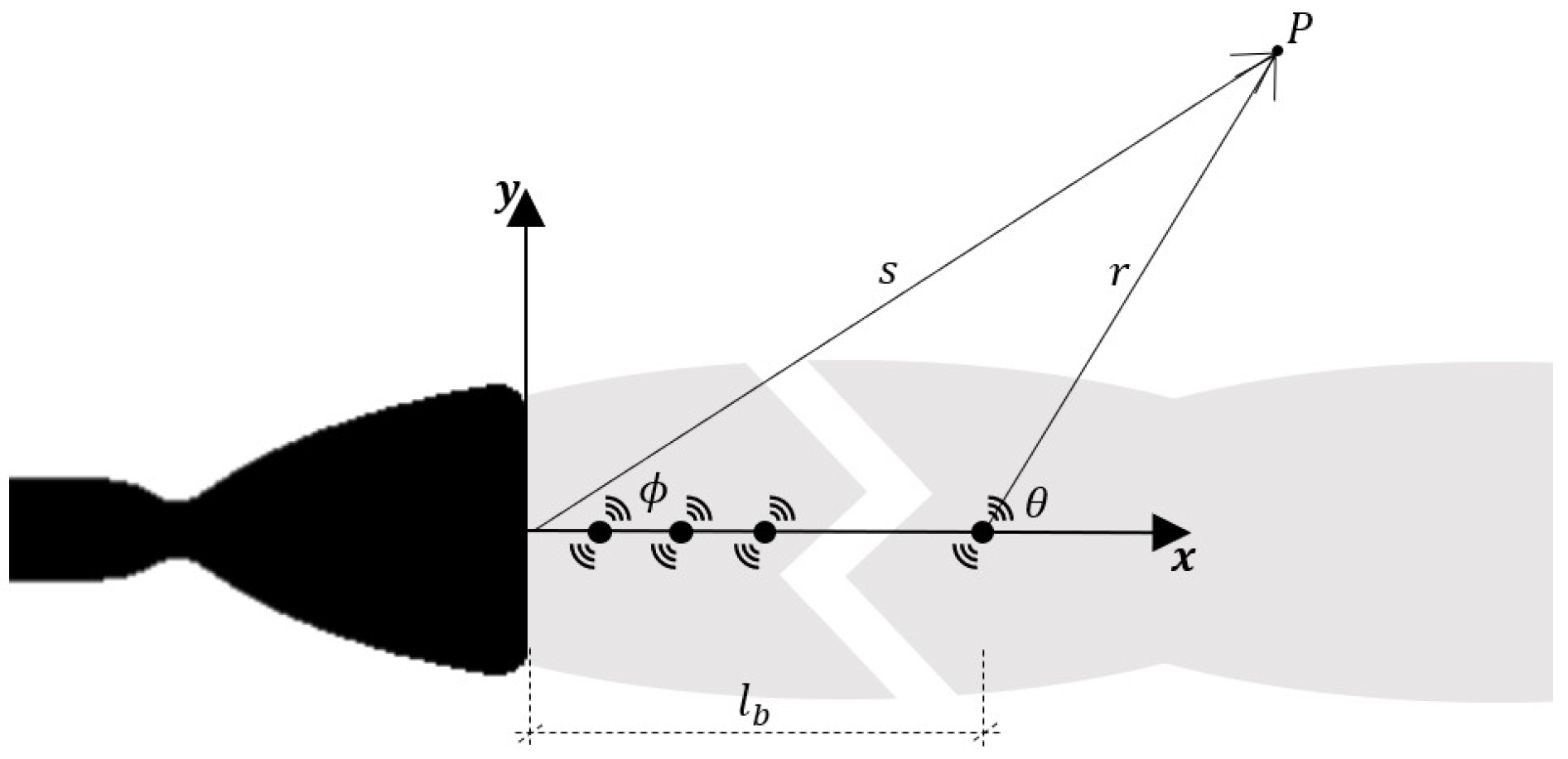
2. Jet Noise Prediction Model

Due to the complex nature of sound generation phenomena in supersonic jets, the prediction of acoustic fields can easily be achieved applying similarity principles, resulting in a rough preliminary estimate. Specifically, the approach proposed by Eldred [11] consists of a semi-empirical method largely based on the Apollo program era background (medium-high thrust standard chemical rockets). Therefore, the relationships between the engine parameters and the noise can generally be exploited only for conventional rocket engines with physical and chemical properties of the exhaust plume, nozzle, and deflector geometric characteristics typical of engines currently in service [11,12].
According to these considerations, a full-scale experimental test campaign is required to assess the feasibility of extending Eldred model to HREs, as could be the 1000 N demonstrator of the HYPROB-NEW project.

Distribution Source Method

The Distribution Source Method (DSM) mentioned in Eldred’s work [11] assumes that the jet noise is modeled by allocating discrete noise sources along the exhaust stream. Since the sound pressure level (SPL) spectrum varies in frequency along the length of the plume as a function of jet characteristics, rocket engine geometry, and position on the launch pad, each discrete noise source will have to act on a specific frequency band with a unique sound power level depending on its location.
Figure 2 schematically represents the rocket engine, the set of acoustic sources distributed along the exhaust stream (distance l b from the nozzle exit measured along the x-axis), and the relative position of the observer (distance r from each source). The angle θ is defined for each source by the line between the source and the observer (point P) and the jet axis. Finally, the distance s and the angle ϕ will be useful to define a unique reference system centered at the nozzle exit.
According to Eldred [11], the overall acoustic power W O A in watts is estimated using:
W O A = η n F U e 2
where η is the ratio between the sound power and the exhaust’s mechanical power, termed acoustical efficiency, n is the number of nozzles, F is the thrust of each engine in Newtons, and U e is the fully expanded jet velocity in meters per second. For highly supersonic jets the sound power is proportional to the mechanical power generated by the engine (proportional to the product of the thrust and the jet velocity), thus, acoustical efficiency result in a constant value. For undeflected standard chemical rocket exhaust, the latter falls in the range of 0.2% and 1%.
The overall sound power level L W , which specifies the power delivered in decibels relative to one picowatt, is given by:
L W = 10 l o g 10 W O A 10 12
Each rocket engine produces a unique sound power spectrum, depending on the physical and chemical properties of the exhaust plume, the geometric characteristics of the nozzle, the thrust, etc. However, a dimensionless analysis allows to obtain a single acoustic spectrum for a wide range of engines, more precisely, the normalized power spectra are weakly dependent on their parameters, with the exception of the Strouhal number. The latter is a dimensionless number used to describe oscillating flow mechanisms, defined as the product of the frequency and the nozzle exit diameter divided by the fully expanded exit velocity.
Figure 3a illustrates how this result has been confirmed by a large number of experiments, while Figure 3b shows the interpolated data for the case study (low-thrust HRE):
The normalized spectrum is then converted to a conventional acoustic power level defined in a generic bandwidth Δ f b by the following relationship [11]:
L W , b = 10 l o g 10 W ( f ) W O A U e d e + L W 10 l o g 10 U e d e + 10 l o g 10 ( Δ f b )
where L W , b represents the sound power level in dB in the band centered on frequency b, while d e is the exit nozzle diameter in meters. A single discrete noise source is assigned a band sound power level, whose strength is defined by Equation (3), and then arranged along the exhaust flow. How these are moved along the plume axis depends on the similarity curves in Figure 4a. In particular, the Strouhal numbers calculated above are useful to interpolate the reference curve for the single-nozzle (undeflected) chemical rocket and estimate the apparent source positions (Figure 4b).
The sound pressure level at position P (Figure 2), in the band centered at frequency b, assuming an omnidirectional spherical source in free-field far from the origin (plane-wave approximation), can be calculated as follows:
S P L b , p = L W , b 10 l o g 10 ( r 2 ) 10 l o g 10 4 π ρ 0 c 0 p 0 2 W 0
where r is the length of the radius line from the source to the observer; p 0 and W 0 are the reference values of 20 µPa and 10 12 W, respectively, (threshold of human hearing); ρ 0 is the ambient air density; and c 0 is the ambient speed of sound in air. The last term in Equation (4) can be well approximated by the value of 11 dB.
However, the sound waves do not propagate uniformly in all directions due to refraction of sound as it is transmitted through the shear layer into the exhaust flow; therefore, it is necessary to adjust the shape of the sound pressure spectra. This is achieved by introducing empirically determined, frequency-dependent directivity indices [11]:
S P L b , p = L W , b 10 l o g 10 ( r 2 ) 11 + D I ( b , θ )
Since the directivity characteristics also depend on the type of engine (Figure 5a), the Strouhal number can be introduced to normalize the directivity diagram to reduce the dependence on its parameters as explained above.
Figure 5b shows the normalized reference curve for the single-nozzle (undeflected) standard chemical rocket as a function of the θ angle and the Strouhal number, and the directivity indices interpolated for the case study.
The dependence on the Strouhal number shows how the sound level generally increases with frequency. The probable cause is the high refraction efficiency at high frequency due to the interaction between the shear layer and the acoustic waves. Indeed, at this frequency, the small acoustic wavelength tends to be comparable to the shear layer width.
Finally, the spectral contribution of each source is logarithmically summed to estimate the overall sound pressure level at any point P around the launch vehicle:
O A S P L p = 10 l o g 10 b 10 S P L b , p 10

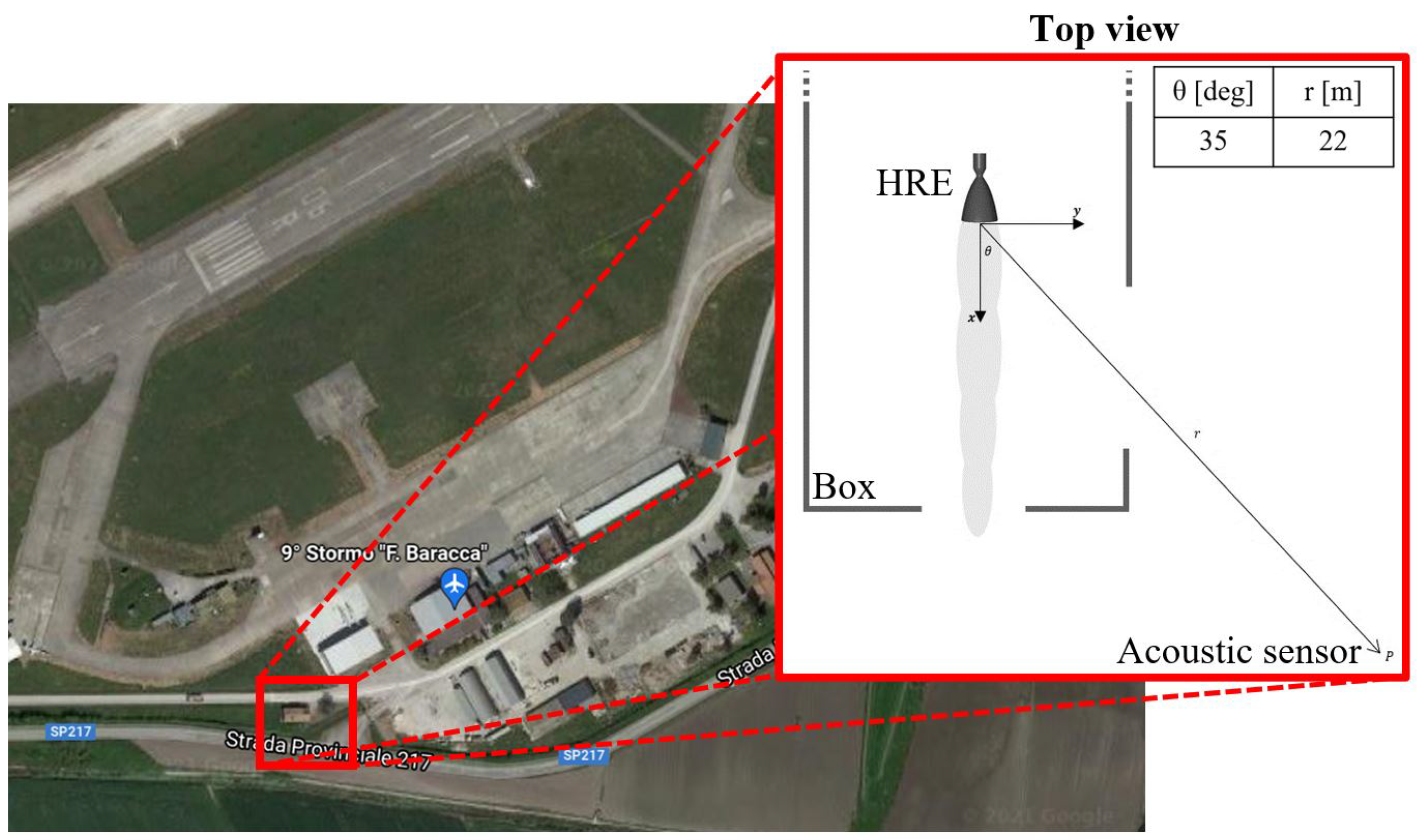
3. Experimental Activity and Results

The experimental activities carried out in the framework of HYPROB-NEW project also allowed to perform acoustic measurements. In this context, acoustic data were collected at the military outdoor firing range located at the Grazzanise Air Force Base, recorded with a 1/2" free-field prepolarized condenser microphone. Data acquisition was handled with a four-channel real-time sound level integrator and analyzer (SoundBook), from the Spectra Corp., with a sampling rate of 51.2 kHz per channel (Figure 6).
The microphone, microphone preamplifier, extension cables, preamplifier power supply, and analyzer present characteristics in accordance with IEC 651 Type 1, IEC 804 Type 1, IEC61672 Class 1, IEC 1260 Class 0. More details on the specifications of the devices are given in Table 1:
The acoustic sensor was deployed at a distance of 22 m from the nozzle exit and at 35° to the plume exhaust axis. Instead, the test article, a 1000 N paraffin-based HRE, was attached to the mount and fixed parallel to the ground in a partially open facility (Figure 7).
The beginning and ending of signal acquisition were performed manually before the countdown and at the end of the test. The 5-second jet noise signal was extracted from the whole recording and analyzed by performing a Fourier transform (Figure 8), with a sampling frequency of 51.2 kHz. According to Shannon’s theorem, the Nyquist frequency is equal to half the sampling frequency (25.6 kHz). This avoids aliasing in the audible spectrum. To reduce noise in the data set, a MATLAB signal toolbox was used for data smoothing, specifically a Savitzky–Golay filter.
The occurrence of multiple tones at a fundamental frequency and its harmonics can be generated by a closed-loop feedback process, namely screech tone. When a supersonic jet is imperfectly expanded, as in the test case, a quasiperiodic shock-cell structure is formed in the jet plume, causing a radiation of additional noise to the turbulent mixing noise: the broadband shock-associated noise and the screech tone. However, the noise directivity [1,2] suggests that the latter is mainly radiated to the rear of the nozzle, while the broadband shock noise and turbulent mixing noise are radiated almost normal to and downstream of the jet axis, respectively. Since the acoustic measurement was performed at approximately 35 degrees from the exhaust flow axis, the turbulent mixing noise is expected to be the most dominant noise component of the spectra. Therefore, the observed SPL peaks are presumably associated with resonance modes of the combustion chamber or post-combustion chamber (Figure 9). In fact, pressure fluctuations within the chambers, e.g., due to the combustion process, can propagate toward the boundary and then be reflected back toward the flame. These waves combine to produce acoustic pressure and velocity oscillations in the vicinity of the boundary; If these acoustic fluctuations are able to alter the combustion rate with the correct phase, they will be converted into higher amplitude acoustic disturbances [16].

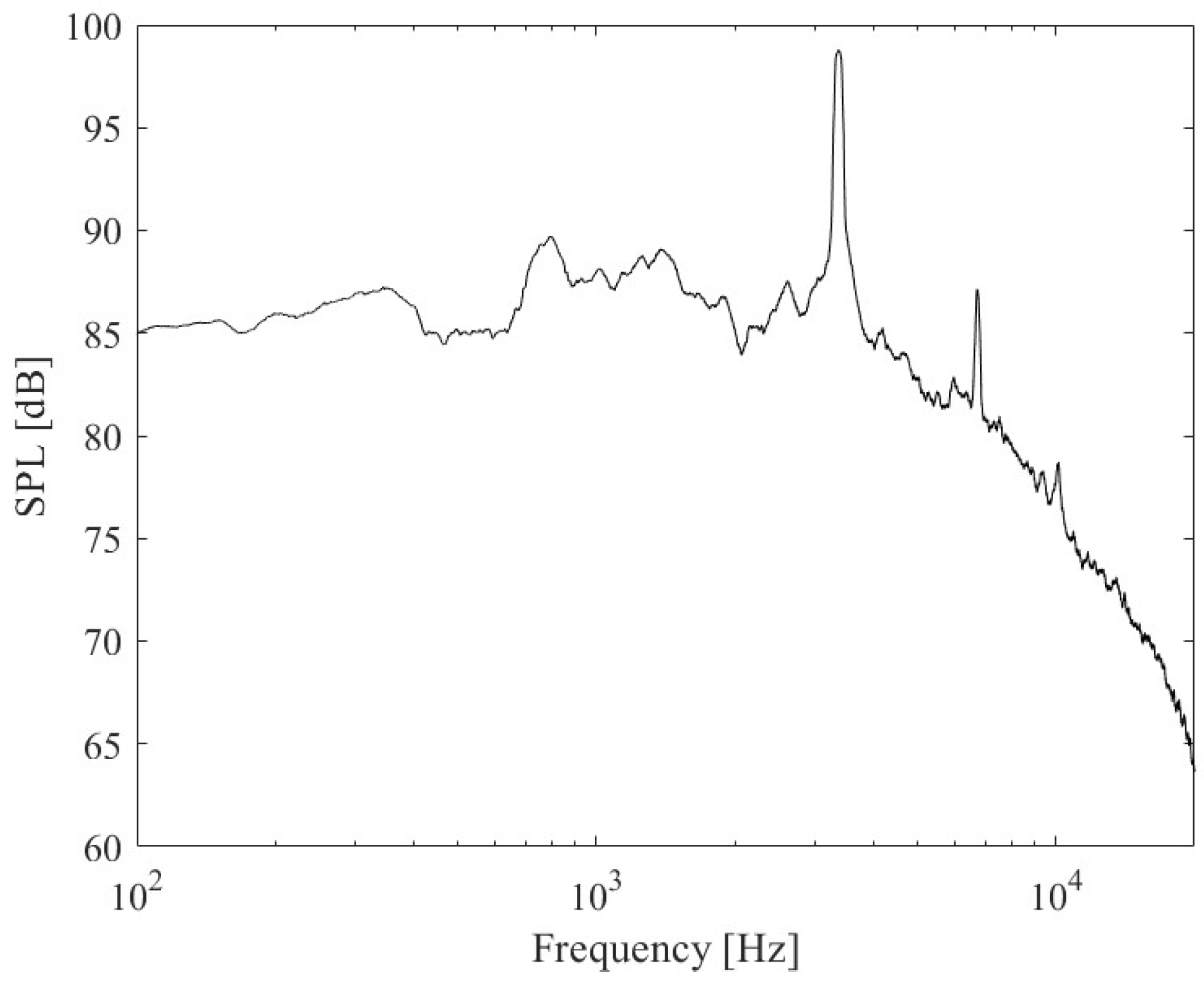
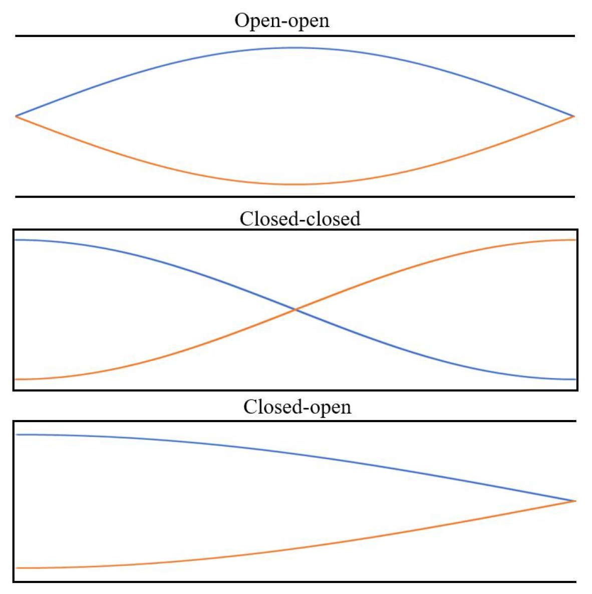
3.1. Analytical Acoustic Analysis of Combustion and Post-Combustion Chambers

A simplified test was designed to investigate the acoustic properties of the HRE cavities, in which the combustion chamber cavity was connected to a modified volume representative of the post-combustion chamber (equivalent simple tube representing the cavity equipped with the nozzle). Based on the type of the acoustic boundary condition different cavity resonance frequencies and modes (Figure 10) are possible [20]. For instance, for a tube with an open end and a closed end longitudinal standing waves with frequencies equal to ( 2 n 1 ) c / ( 4 L ) can be established whereas for a tube closed at both ends or open at both ends, the wavelength associated with the fundamental frequency is twice the tube length, so, the natural frequencies will be n c / ( 2 L ) . Specifically, n is the mode index, L is the effective acoustic length, and c is the speed of sound.
As a result of the simple geometry, the effective acoustic length of the combustion chamber matches the geometric length, while the effective acoustic length of the post-combustion chamber can be set equal to the distance between the left side and the nozzle throat, less approximately one-half of the converging nozzle length [23]. The computational fluid dynamics (CFD) analysis carried out as part of the HYPROB project revealed a slight difference between the average temperature of the chamber and that of the post-combustion chamber (chamber temperature is approximately 3 percent higher than post-combustion chamber). Therefore, the sound speed was assumed to be approximately constant and is estimated by averaging the values measured in the two chambers.
The pipe eigenfrequencies for various boundary conditions were then evaluated and overlaid on the jet noise spectrum in Figure 11. The blue dotted line and the red dotted line indicate the chamber eigenfrequencies for the open–open (o-o) and closed–open (c-o) boundary conditions, respectively, while the blue and red stars represent the eigenfrequencies corresponding to the post-chamber modes with c-c and c-o boundary conditions, respectively.
Due to the size of the chambers (the length of the combustion chamber is an integer multiple of the equivalent representative volume length of the post-combustion chamber), an acoustic coupling pattern occurs, and the high efficiency of sound transmission could be the consequence of such interaction. In order of frequency, the mode couplings involve:
  • The first post-combustion chamber longitudinal mode closed–open with the third combustion chamber longitudinal mode closed–open;
  • The first post-combustion chamber longitudinal mode closed–closed with the fifth combustion chamber longitudinal mode open–open;
  • The second post-combustion chamber longitudinal mode closed–open with the eighth combustion chamber longitudinal mode closed–open;
  • The second post-combustion chamber longitudinal mode closed–closed with the tenth combustion chamber longitudinal mode open–open.
The analytical solutions are collected and compared with the experimental values in Table 2. Included in this table are the percentage relative errors, computed as:
% E r r o r = | f E x p f | f E x p 100
In a conventional liquid propellant rocket engine, the acoustic coupling involves the interaction between the modes of the injector system and the combustion chamber, while in a hybrid rocket engine the same occurs between the combustion chamber and the post-combustion chamber. Specifically, referring to investigations on combustion instabilities due to resonant coupling for standard engines, the combustion chamber can be reasonably assumed to be a closed cavity due to the short nozzle and the injector plate [23,24]. The same happens in the post-combustion chamber of a hybrid rocket engine. Therefore, the assumption of a closed–closed post-combustion chamber makes sense. Instead, still in the case of a standard engine, the presence of an orifice between the manifold and the injector suggests the use of an acoustically closed inlet [22]. An acoustically open end can also be assumed if the injector tube is connected to a large volume, which could be typical of a combustion chamber [21]. In a hybrid rocket engine, the choke between the pre-chamber and the combustion chamber allows the assumption of a closed acoustic boundary, while the connection of the combustion chamber to a much larger post-combustion chamber approximates an acoustically open boundary. On the other hand, when considering a low Mach number flow through the throttle orifice (between 0.03 and 0.06), the behavior is closer to the open–open case [21].
Considering all configurations normally encountered in the study of instability phenomena for conventional engines (i.e., all those presented above), an atypical acoustic boundary condition seems to coexist in hybrid rocket engines. Specifically, it is the closed–open condition associated with the post-combustion chamber (in conventional engines, this cavity is representative of the combustion chamber), which is normally considered closed–closed. This could be attributed to the small radial size difference between the combustion and post-combustion chambers, which provides a different impedance at the interface compared to traditional rocket engines. Needless to say, this is speculation and needs to be further investigated.
Regarding the coexistence of different coupling conditions, theoretical studies support the possibility of simultaneous configurations [19].

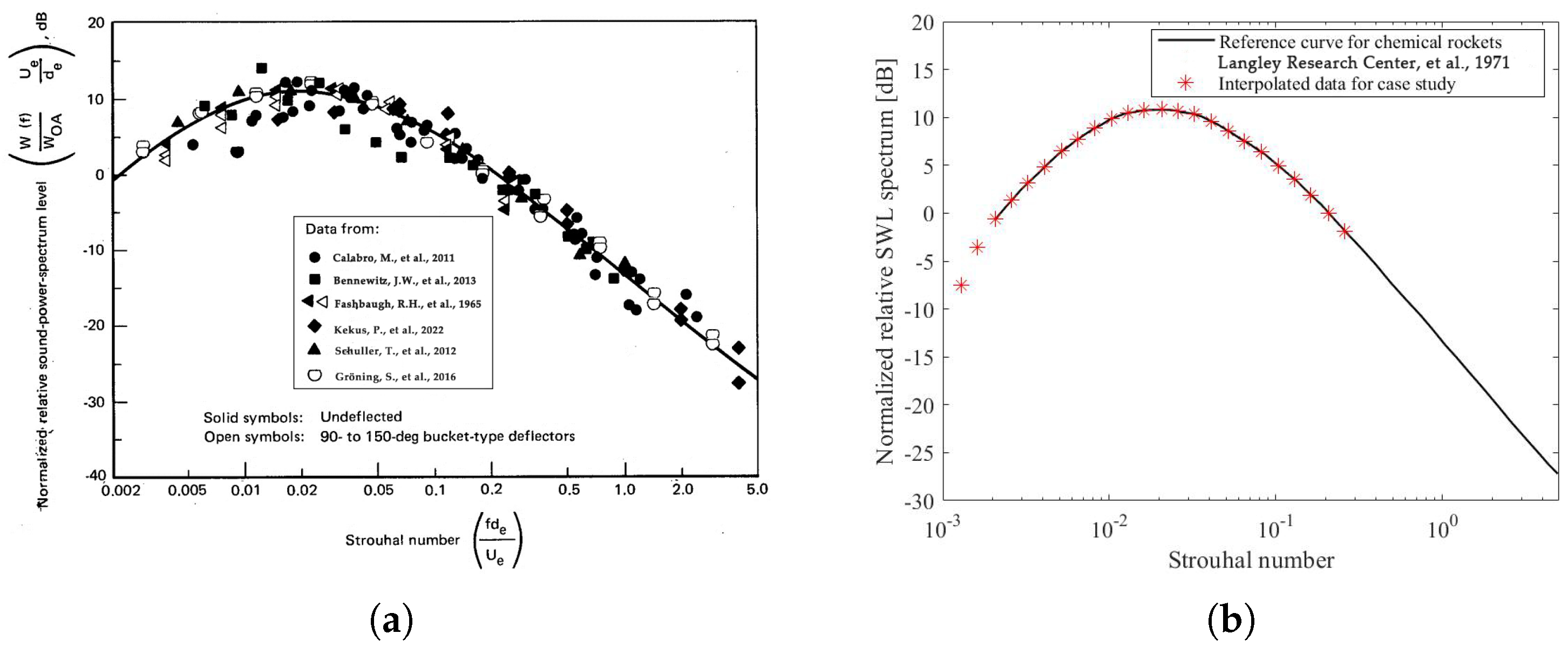
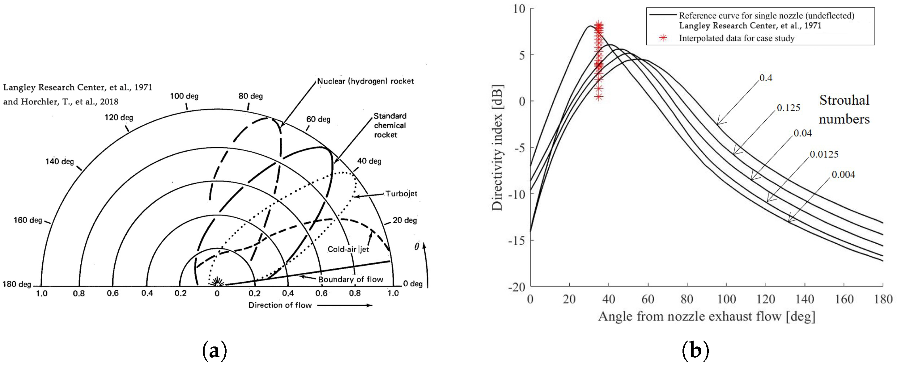
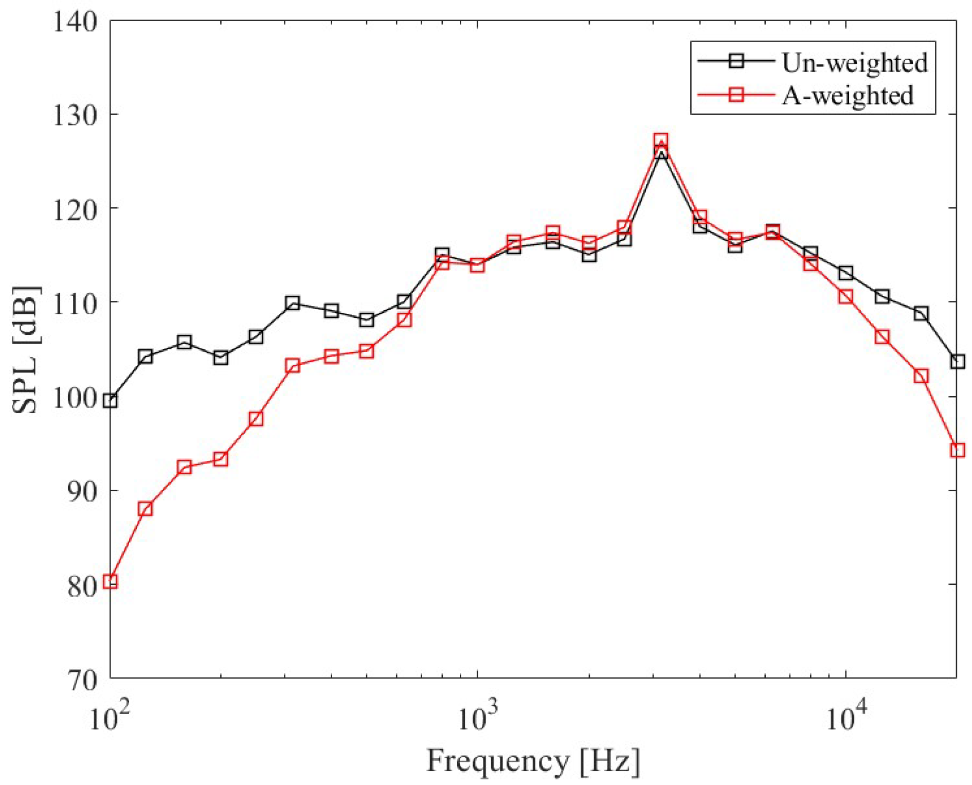
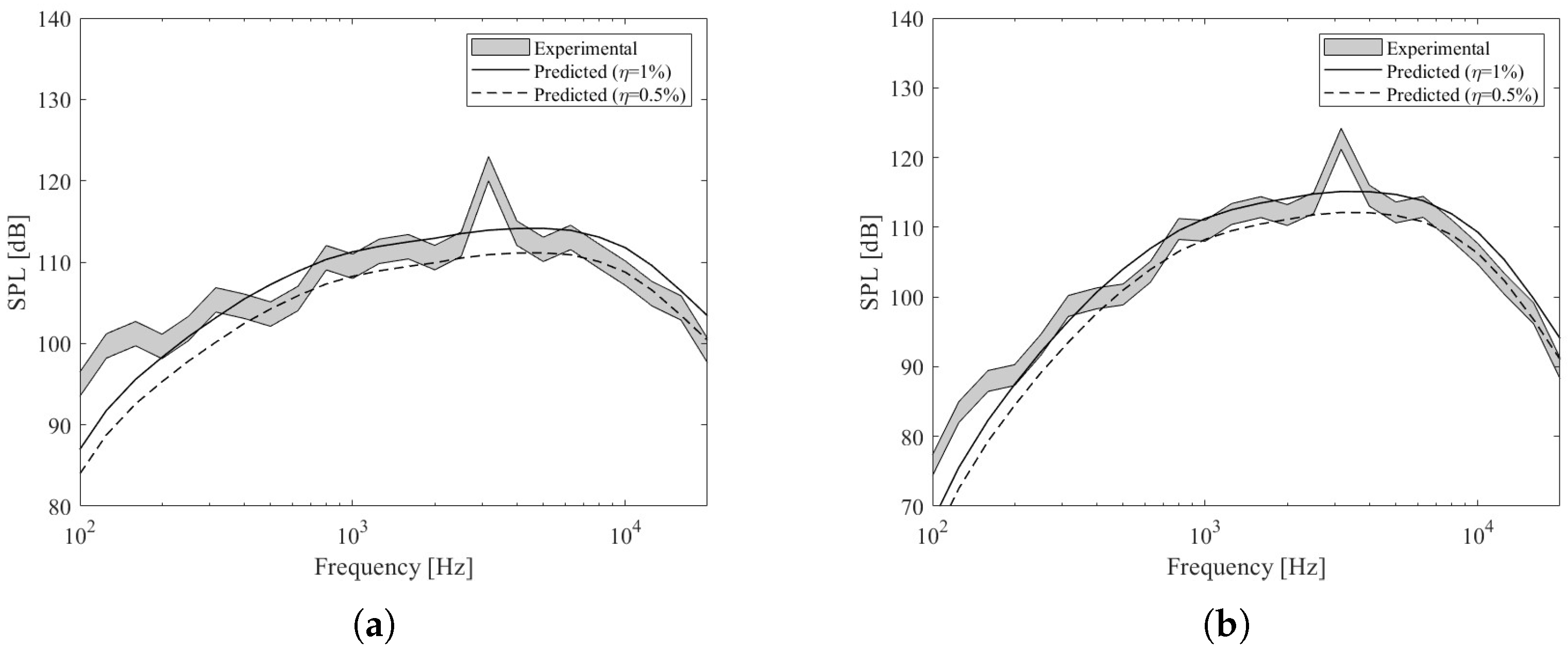
3.2. Eldred Model Results

In order to compare the experimental data with the theoretical predictions, the narrow-band sound pressure level was converted into one-third octave bands, as shown in Figure 12. In addition, A-weighting was applied to the SPL in an effort to describe the effective level perceived by the human ear, which is less sensitive to low frequencies.
The effect of large reflective surfaces, such as the concrete ground parallel to the tested engine, should be included in the prediction by estimating the additional noise to the considered point. Therefore, in this work the sound pressure level was adjusted based on the following considerations. The sum of two identical signals (e.g., the direct and the reflected waves) with the same phase (coherent), produces an SPL of +6 dB compared to the single signal’s SPL. However, in this work the relative phase between the direct signal and its reflection is not known, so in general, there could be both a sum of in-phase signals (+6 dB SPL), and the opposite effect, that is, a total cancellation when the phases have a difference of 180 degrees. Thus, considering fully incoherent sources represents the only way to describe the reflection phenomenon. More specifically, the summation of two incoherent signals will result in an SPL of +3 dB with respect to the single signal’s SPL. To conclude, it is reasonable to expect an increase in sound field levels of 3–6 dB [11], assuming perfect reflection (no absorption by the ground).
Figure 13 shows the comparison between the predicted noise results and the experimental data.
For the reasons explained above, the expected experimental SPL range (without reflection component) is obtained by subtracting 3 and 6 dB from the original experimental curve (gray band). The solid and dashed black lines represent the predicted curve (obtained by Eldred’s procedure) assuming 1% and 0.5% acoustic efficiency values.
Eldred’s empirical method is estimated to have an accuracy of ±4 dB in terms of overall sound pressure level. Analysis of the case study curves confirms that these values are within these limits. In particular, considering the case of completely incoherent sources (OASPL-3 dB) in relation to the prediction for the HRE assuming an acoustic efficiency of 1% (upper limit), it can be stated that the trend of the sound pressure spectrum curves is quite similar, with a Δ OASPL of 2.2 dB for the un-weighted SPL and a Δ OASPL of 2.68 dB for the A-weighted SPL case. For more details, see Table 3:
Although there is a large difference between the expected experimental SPL and Eldred’s predicted SPL at low frequencies (Figure 13), the predicted OASPL is essentially correct. The reason is that the energy at these frequencies is very low (the graph is in dB scale) and an error would not affect the total energy content. From a physical point of view, such a mismatch could be explained by the occurrence of wave diffraction phenomena, which normally result in constructive and destructive interference. They occur when waves pass through a structure whose dimensions are close to the wavelength of sound. In the test case, at 160 Hz, the corresponding wavelength of 2 m becomes comparable to the size of the box.
On the other hand, considering the case of fully coherent and in-phase signals (OASPL-6 dB) compared to Eldred’s prediction assuming an acoustic efficiency of 0.5% (lower limit), the same previous trend in the sound pressure spectrum curves is observed (all curves are simply shifted by 3 dB). In fact, the difference from the previous comparison is a factor of 0.5 in Equation (2). This results in −3 dB of the overall sound power level ( 20 l o g 10 [ 1 / 2 ] ). Therefore, as shown in Table 4, the lower limit case outcomes can be obtained by merely subtracting 3 dB from the already calculated OASPLs. This also means that the results for the Δ OASPLs do not change from the previous case.
In summary, assuming an acoustic efficiency ranging from 0.5% to 1%, Eldred’s prediction recovers the expected experimental SPL in both limit cases. Specifically, due to the unknown amount of reflected energy, the above comparisons do not allow for a fully accurate acoustic characterization of the HRE under investigation; nevertheless, it can be stated that the value of its acoustic efficiency falls within the common range for conventional rocket engines, namely 0.2–1% [11]. These results are quite general, as a generic hybrid propulsion system has roughly similar features compared to the one analyzed here, so it is reasonable to assume that even other low-thrust hybrid rocket engines convert less than 1% of their mechanical power into acoustic energy.
Furthermore, it should be emphasized that Eldred’s technique cannot account for the SPL peaks due to the coupled modes of cavities resonance. Nevertheless, even without implementing corrections, the predicted OASPL is in agreement with the experimentally measured (within 4 dB [11]). The model consistency can thus be exploited to support the goodness of noise level estimation for nearby regions. For example, to assess the noise impact on local communities as a function of sound power distribution along the jet, or simply to estimate the noise load on the rocket or launch pad. To illustrate this possibility, OASPLs were calculated for an area of 70 × 100 m (Figure 14):
As presented in the previous section, Eldred method [11] involves the use of empirically determined frequency-dependent directivity inidices for a standard chemical rocket engine. Therefore, the simulated directional characteristics of the noise produced by low-thrust HREs exhibit a critical zone along a line inclined approximately 45° from the jet plume, as for conventional propulsion systems. Although these are probably the most appropriate values to use even for HRE, their accuracy is generally questionable.

4. Conclusions

A semi-empirical method proposed by Eldred for predicting rocket jet noise was described and applied to the low-thrust hybrid rocket engine (paraffin–oxygen based) developed as part of the Italian Aerospace Research Centre’s HYPROB project. Such an approach utilizes empirical curves, derived from a series of measurements carried out during the Apollo era, to distribute the overall acoustic power along the plume axis into multiple acoustic monopoles, and then uses the acoustic propagation theory to predict the radiated sound levels as a function of frequency, distance, and direction from the plume. Since the method is based on past experimental data, good results are generally obtained for nozzle design, exhaust flow characteristics, and thrusts typical of high-thrust liquid/solid rocket engines. Therefore, the experimental data gathered during a firing test campaign, conducted by CIRA, were valuable to asses the potential of extending current empirical methods to rocket engine concepts significantly different from existing configurations, i.e., low-thrust hybrid rocket engines.
The experimental activity was carried out at the military outdoor firing range located at the Grazzanise Air Force Base. Acoustic data were recorded with a 1/2" free-field prepolarized condenser microphone, while data acquisition was handled with a sound level integrator and analyzer (sampling rate 51.2 kHz per channel). Specifically, the acoustic sensor was deployed 22 m from the nozzle exit and at an angle of 35° to the plume exhaust axis. The experimental sound pressure level was computed performing a Fourier transform of the 5-s jet noise signal and adjusted to account for the effect of large reflective surfaces, such as the concrete ground parallel to the engine under test.
In this scenario (i.e., the presence of reflective surfaces), according to Eldred’s work, it is reasonable to expect an increase in sound field levels of 3–6 dB. Therefore, in order to exclude the energy component due to the reflection phenomenon, an expected experimental sound pressure level range (original SPL-3 dB and original SPL-6 dB) was established. The presence of 3 dB range prevented a fully accurate acoustic characterization of the HRE under investigation; nevertheless, it was possible to determine that its acoustic efficiency (between 0.5 and 1%) falls within the common range for conventional rocket engines (between 0.2 and 1%). Moreover, since a generic hybrid propulsion system has roughly similar features compared to the one analyzed here, these results are reasonably quite general. In summary, the powerful features of the Eldred model (prediction of noise levels in nearby regions, or simple estimation of acoustic loads on the rocket or launch pad) appear to be applicable to low-thrust hybrid rocket engines as well.
Besides the main activity, a simple study on resonant cavity modes was undertaken to explain some of the anomalies observed in the measured jet noise spectrum (unexpected spike). The size of the combustion and post-combustion chambers has been identified as the cause of longitudinal modes coupling. In particular, this phenomenon can manifest itself as an increase in the acoustic efficiency for some frequencies of the spectrum. These types of couplings can also induce large amplitude structural vibrations, with consequent detrimental effects on both engine operation and durability; therefore, identifying the occurrence of such phenomena and reducing or eliminating them is a critical step in rocket engine design. Acoustic analysis also revealed that certain modes couplings in the hybrid engine are unusual for conventional liquid rocket engines. Indeed, according to experimental and numerical studies of instability phenomena for standard chemical engines, closed–open and open–open are typical acoustic boundaries for the injector system (component analogous to the combustion chamber for the hybrid rocket engine configuration), while the combustion chamber can reasonably be assumed to be a closed cavity (component analogous to the post-combustion chamber for the hybrid rocket engine configuration). In hybrid rocket engines, however, an atypical acoustic boundary condition seems to coexist. Specifically, it corresponds to the closed–open condition of the post-combustion chamber, which is coupled, in the case study, to the closed–open configuration of the combustion chamber. The cause of this phenomenon is unknown and requires further investigation.

Author Contributions

Conceptualization, G.F. and L.F.; methodology, G.F.; software, G.F.; formal analysis, G.F.; investigation, A.S. and L.D.V.; resources, L.F., A.S. and L.D.V.; data curation, G.F. and L.F.; writing—original draft preparation, G.F.; writing—review and editing, R.C.; visualization, G.F.; supervision, L.F. All authors have read and agreed to the published version of the manuscript.

Funding

This research received no external funding.

Institutional Review Board Statement

Not applicable.

Informed Consent Statement

Not applicable.

Data Availability Statement

Data will be made available on request.

Acknowledgments

The authors would like to express their gratitude to their colleagues from CIRA’s TPAS laboratory (in particular, Francesco Battista and Daniele Cardillo), who are involved in the HYPROB-NEW project, for making it possible to carry out acoustic measurements during the ongoing experimental campaign on hybrid propulsion systems and for providing some of the input data of the jet noise prediction model.

Conflicts of Interest

The authors declare no conflict of interest.

Abbreviations

The following abbreviations are used in this manuscript:
DNSDirect Navier–Stokes
LESLarge Eddy Simulation
RANSReynolds Averaged Navier–Stokes
CFDComputational Fluid dynamics
CIRAItalian Aerospace Research Centre
HREHybrid Rocket Engine
DSMDistribution Source Method
SPLSound Pressure Level
OASPLOverall Sound Pressure Level
DIDirectivity Index
FEMFinite Element Method

References

  1. Tam, C.K. Supersonic jet noise. Annu. Rev. Fluid Mech. 1995, 27, 17–43. [Google Scholar] [CrossRef]
  2. Tam, C.; Golebiowski, M.; Seiner, J. On the two components of turbulent mixing noise from supersonic jets. In Proceedings of the Aeroacoustics Conference, State College, PA, USA, 6–8 May 1996. [Google Scholar]
  3. Bianco, D.; Adamo, F.P.; Barbarino, M.; Vitiello, P.; Bartoccini, D.; Federico, L.; Citarella, R. Integrated Aero–Vibroacoustics: The Design Verification Process of Vega-C Launcher. Appl. Sci. 2018, 8, 88. [Google Scholar] [CrossRef] [Green Version]
  4. Citarella, R.; Federico, L. Advances in Vibroacoustics and Aeroacustics of Aerospace and Automotive Systems. Appl. Sci. 2018, 8, 366. [Google Scholar] [CrossRef] [Green Version]
  5. Citarella, R.; Federico, L.; Barbarino, M. Aeroacustic and vibroacoustic advancement in aerospace and automotive systems. Appl. Sci. 2020, 10, 3853. [Google Scholar] [CrossRef]
  6. Zoppellari, E.; Juve, D. Reduction of jet noise by water injection. In Proceedings of the 3rd AIAA/CEAS Aeroacoustics Conference, Atlanta, GA, USA, 12–14 May 1997. [Google Scholar]
  7. Barbarino, M.; Ilsami, M.; Tuccillo, R.; Federico, L. Combined CFD-Stochastic Analysis of an Active Fluidic Injection System for Jet Noise Reduction. Appl. Sci. 2017, 7, 623. [Google Scholar] [CrossRef] [Green Version]
  8. Barbarino, M.; Ilsami, M.; Tuccillo, R.; Federico, L. Design Of Active Fluidic Injection Systems For Jet-Noise Reduction Through Stochastic Reconstruction Of Turbulent Flow Fields. In Proceedings of the International Congress on Sound and Vibration in Aeroacoustics Conference, London, UK, 23–27 July 2017. [Google Scholar]
  9. Brès, G.A.; Lele, S.K. Modelling of jet noise: A perspective from large-eddy simulations. Philos. Trans. R. Soc. 2019, 377, 2159. [Google Scholar] [CrossRef] [PubMed] [Green Version]
  10. Goldstein, M. A hybrid RANS/LES approach for predicting jet noise. In Proceedings of the 12th AIAA/CEAS Aeroacoustics Conference, Cambridge, MA, USA, 8–10 May 2006. [Google Scholar]
  11. Langley Research Center; Eldred, K.M. Acoustic Loads Generated by the Propulsion System; National Aeronautics and Space Administration: Washington, DC, UDA, 1971.
  12. Lubert, C.P.; Gee, K.L.; Tsutsumi, S. Supersonic jet noise from launch vehicles: 50 years since NASA SP-8072. J. Acoust. Soc. Am. 2022, 151, 752–791. [Google Scholar] [CrossRef] [PubMed]
  13. Battista, F.; Cardillo, D.; Fragiacomo, M.; Di Martino, G.D.; Mungiguerra, S.; Savino, R. Design and Testing of a Paraffin-Based 1000 N HRE Breadboard. Aerospace 2019, 6, 89. [Google Scholar] [CrossRef] [Green Version]
  14. Venugopal, S.; Rajesh, K.K.; Ramanujachari, V. Hybrid rocket technology. Def. Sci. J. 2011, 61, 193. [Google Scholar] [CrossRef] [Green Version]
  15. Calabro, M. Overview on hybrid propulsion. Prog. Prop. Phys. 2011, 2, 353–374. [Google Scholar]
  16. Bennewitz, J.W.; Frederick, R.A. Overview of combustion instabilities in liquid rocket engines-coupling mechanisms & control techniques. In Proceedings of the 49th AIAA/ASME/SAE/ASEE Joint PropulsionConference, San Jose, CA, USA, 14–17 July 2013. [Google Scholar]
  17. Fashbaugh, R.H.; Streeter, V.L. Resonance in liquid rocket engine systems. J. Basic Eng. 1965, 87, 1011–1017. [Google Scholar] [CrossRef]
  18. Kekus, P. Acoustic Analysis of a Liquid-Propellant Rocket Engine: Optimisation of the Meshing Strategy. In Proceedings of the 2nd International Conference on Flight Vehicles, Aerothermodynamics and Re-Entry Missions & Engineering, Heilbronn, Germany, 19–23 June 2022. [Google Scholar]
  19. Horchler, T. Selection Rules for Resonant Longitudinal Injector-Coupling in Experimental Rocket Combustors. Aerospace 2022, 9, 669. [Google Scholar] [CrossRef]
  20. Schuller, T.; Durox, D.; Palies, P.; Candel, S. Acoustic decoupling of longitudinal modes in generic combustion systems. Combust. Flame 2012, 159, 1921–1931. [Google Scholar] [CrossRef]
  21. Gröning, S.; Hardi, J.S.; Suslov, D.; Oschwald, M. Injector-driven combustion instabilities in a hydrogen/oxygen rocket combustor. J. Propuls. Power 2016, 32, 560–573. [Google Scholar] [CrossRef]
  22. Horchler, T.; Armbruster, W.; Hardi, J.; Karl, S.; Hannemann, K.; Gernoth, A.; De Rosa, M. Modeling combustion chamber acoustics using the DLR TAU code. In Proceedings of the Space Propulsion Conference, Seville, Spain, 14–18 May 2018. [Google Scholar]
  23. Pirk, R.; Souto, C.D.A.; Silveira, D.D.D.; Souza, C.M.D.; Góes, L.C.S. Liquid rocket combustion chamber acoustic characterization. J. Aerosp. Technol. Manag. 2010, 2, 269–278. [Google Scholar] [CrossRef]
  24. Yu, Y.; Koeglmeier, S.; Sisco, J.; Anderson, W. Combustion instability of gaseous fuels in a continuously variable resonance chamber (CVRC). In Proceedings of the 44th AIAA/ASME/SAE/ASEE Joint Propulsion Conference & Exhibit, Hartford, CT, USA, 21–23 July 2008. [Google Scholar]
Figure 1. The 1000 N HYPROB demonstrator during firing test.
Applsci 13 09041 g001
Figure 2. Schematic representation of the noise sources distribution according to Eldred’s method.
Applsci 13 09041 g002
Figure 3. Normalized relative sound power spectrum as a function of Strouhal number. (a) Experimental data for standard chemical rockets with single nozzle (1.56 to 31,100 kN) [15,16,17,18,20,21]. (b) Data interpolation on the basis of case study input information [11].
Applsci 13 09041 g003
Figure 4. Axial location of sources for single nozzle, undeflected standard chemical rocket engine. (a) Apparent source positions for the single-nozzle (undeflected) chemical rocket [11]. (b) Source positions for the case study.
Applsci 13 09041 g004
Figure 5. Rocket engine sound directivity properties. (a) OASPL directivity for different type of jet flow [11,22]. (b) DI for standard chemical rockets and for the case study [11].
Applsci 13 09041 g005
Figure 6. Experimental apparatus schematic diagram.
Applsci 13 09041 g006
Figure 7. Test facility and test set-up sketch.
Applsci 13 09041 g007
Figure 8. Sound pressure level 1000 N hybrid rocket engine (22 m and 35°).
Applsci 13 09041 g008
Figure 9. CIRA 1000 N HRE section [13].
Applsci 13 09041 g009
Figure 10. First acoustic eigenmode for various boundary conditions.
Applsci 13 09041 g010
Figure 11. SPL spectra compared to the combustion chamber and post-combustion chamber eigenfrequencies, for various boundary conditions.
Applsci 13 09041 g011
Figure 12. The 1/3 octave Un-/A-weighted SPL 1000 N hybrid rocket engine (22 m and 35°).
Applsci 13 09041 g012
Figure 13. Expected experimental SPL range (gray shape) compared to predicted SPL with 1% (solid black line) and 0.5% (dashed black line) acoustic efficiency. (a) Un-weighted SPL. (b) A-weighted SPL.
Applsci 13 09041 g013
Figure 14. Acoustic field estimated on an area 70 × 100 m (1% of acoustic efficiency). The engine is located at the origin of the axes (0,0), while the plume is oriented along the positive x-coordinate. (a) Un-weighted OASPL. (b) A-weighted OASPL.
Applsci 13 09041 g014
Table 1. Equipment specifications.
EquipmentModelFrequency RangeDynamic Range
MicrophonePCB 377B02±2 dB (3.15 Hz to 20 kHz)147 dB (3% distortion limit)
Microphone preamplifierPCB 426A30±0.1 dB (10 Hz to 126 kHz)-
Preamplifier power supplyLarson Davis 2221±0.2 dB (10 Hz to 100 kHz)-
Table 2. Natural frequencies of HRE chambers, with relative error.
# Coupling FrequencyExperimental Frequencies (Hz)Analytical Frequencies (Hz)Error (%)
1st336433600.12
2nd672567210.06
3rd10,12710,0810.45
4th13,52813,4420.64
Table 3. Assumption of incoherent signals (OASPL-3 dB) compared to the prediction considering 1% of the acoustic efficiency.
Frequency WeightingPredicted OASPL (dB)Experimental OASPL (dB) Δ OASPL (dB)
Un-weighted124.35126.552.20
A-weighted124.39127.072.68
Table 4. Assumption of coherent signals (OASPL-6 dB) compared to the prediction considering 0.5% of the acoustic efficiency.
Frequency WeightingPredicted OASPL (dB)Experimental OASPL (dB) Δ OASPL (dB)
Un-weighted121.35123.552.20
A-weighted121.39124.072.68
Disclaimer/Publisher’s Note: The statements, opinions and data contained in all publications are solely those of the individual author(s) and contributor(s) and not of MDPI and/or the editor(s). MDPI and/or the editor(s) disclaim responsibility for any injury to people or property resulting from any ideas, methods, instructions or products referred to in the content.

