Article

Implementation of the HHL Algorithm for Solving the Poisson Equation on Quantum Simulators

Department of Computer Science, Faculty of Information Technology, Al-Farabi Kazakh National University, Almaty 050040, Kazakhstan
*
Author to whom correspondence should be addressed.
Appl. Sci. 2023, 13(20), 11491; https://doi.org/10.3390/app132011491
Submission received: 13 September 2023 / Revised: 10 October 2023 / Accepted: 17 October 2023 / Published: 20 October 2023
(This article belongs to the Special Issue Quantum Computation in Quantum Science)

Abstract

:
The Poisson equation is a fundamental equation of mathematical physics that describes the potential distribution in static fields. Solving the Poisson equation on a grid is computationally intensive and can be challenging for large grids. In recent years, quantum computing has emerged as a potential approach to solving the Poisson equation more efficiently. This article uses quantum algorithms, particularly the Harrow–Hassidim–Lloyd (HHL) algorithm, to solve the 2D Poisson equation. This algorithm can solve systems of equations faster than classical algorithms when the matrix A is sparse. The main idea is to use a quantum algorithm to transform the state vector encoding the solution of a system of equations into a superposition of states corresponding to the significant components of this solution. This superposition is measured to obtain the solution of the system of equations. The article also presents the materials and methods used to solve the Poisson equation using the HHL algorithm and provides a quantum circuit diagram. The results demonstrate the low error rate of the quantum algorithm when solving the Poisson equation.

1. Introduction

The Poisson equation is one of the fundamental equations of mathematical physics that describes the potential distribution in static fields. The solution of the Poisson equation on a 2D grid can have numerous practical applications in various fields of science and technology, including semiconductor physics, optics, and mechanics, among others. However, conventional methods for solving the Poisson equation on a grid demand significant computational resources and encounter the issue of exponential growth in computational complexity as the grid dimension increases. In this context, new approaches to solving the Poisson equation on quantum computers have emerged, potentially offering advantages over classical methods.
One approach is based on the use of quantum computers to solve the Poisson equation on a grid. This approach allows the properties of quantum mechanics, such as the superposition of states, parallel operations, and quantum transformations, to be effectively utilized in solving the problem.
In addition, several papers focus on solving the Poisson equation using quantum computers. For example, in ref. [1], the authors focus on the numerical solution of the Poisson equation. The authors specifically propose a quantum method and a scalable quantum scheme that roughly approximates the grid-based solution to the Poisson equation. In ref. [2], the authors discuss various quantum algorithms for solving linear systems of equations, including the Poisson equation. In ref. [3], the gate insulator is investigated using a quality control simulator and IBM equipment, and the authors use quantum computing to solve the Poisson equation. In ref. [4], the authors create a spectral technique for more complex second-order elliptic equations and a quantum finite difference method for the Poisson equation. It is also worth mentioning the article [5], in which the authors propose a variational quantum algorithm (VQA) that can be used with noisy medium-scale quantum computers to solve the Poisson equation. Additionally, there is also the work [6], in which the authors present a quantum algorithm for solving the wave equation, which can be related to the Poisson equation in some applications. In ref. [7], the author describes a quantum algorithm for solving nonlinear differential equations, which, in some cases, can be applied to solve the Poisson equation. In ref. [8], the HHL algorithm is used to solve the Poisson equation for the p-n junction of a semiconductor nanowire at the Neumann boundary, confirming that there is no electric field at the electrode boundaries. It was found that the model of quantum gates proposed by the authors for the implementation of the Neumann boundary condition, in combination with an appropriately executed non-uniform grid, successfully reproduces the result obtained by the traditional method. In ref. [9], the authors present numerous PDE solutions on a quantum computer. Quantum algorithms for differential equations find practical implementation even within these works [10,11,12,13,14,15].
To solve the Poisson equation on a 2D grid, one can use the finite difference method. This method consists of approximating the second derivative concerning x and y using difference expressions. The result is a system of equations that can be solved numerically. However, this method can be resource intensive and slow when there is a large number of mesh nodes and complex boundary conditions.
These are just a few examples of the work that has been done on solving the Poisson equation using quantum computers. However, it should be noted that quantum computing is still at an early stage of development, and the practical application of quantum algorithms to solve real-world problems requires further research and development.
In oil production problems, the Poisson equation is used to model fluid flow in a porous medium, determine pressure distribution, and predict fluid flow. This makes it possible to calculate the distribution of pressure potential in underground reservoirs and determine the optimal points for drilling wells. However, the Poisson equation also has its limitations and problems. Most practical situations require the use of numerical methods to solve the Poisson equation. This can be resource intensive and requires significant computing power.
The use of quantum algorithms to solve the Poisson equation can offer the promise of speeding up computations and improving the accuracy of simulations. An example of a quantum algorithm that can be applied to solve the Poisson equation is the HHL algorithm. HHL can be used to find an approximate solution to the Poisson equation with a given accuracy.
The HHL algorithm was developed by Harrow, Hassidim, and Lloyd in 2009 and is a quantum algorithm that allows you to solve systems of linear equations faster than classical algorithms. The main idea of the algorithm is to use the modulo Fourier transform, as well as the inverse Fourier transform, to transform the state vector encoding the solution of the system of equations into a superposition of states corresponding to the significant components of this solution. This makes it possible to efficiently process information about the solution of a system of equations and obtain results much faster than in classical calculations. When applying the HHL algorithm to the solution of the Poisson equation in the two-dimensional case, the grid is divided into nodes, and the corresponding matrix A becomes sparse. In the classical case, solving such systems requires a lot of computing resources, while the HHL algorithm allows you to obtain a solution using a much smaller number of operations.

2. Materials and Methods

2.1. Difference Scheme of the Poisson Equation

In the 2D case, the Poisson equation is written as
2u/∂x2 + 2u/∂y2 = −f(x,y)
where u is an unknown function that determines the distribution of the potential in the 2D region given by variables x and y [16]. The function f(x,y) represents sources in this area. This equation can be used to model electrostatic fields, fluid flows, temperature distribution in areas with variable thermal conductivity, etc.
The problem is to find a function f(x,y) that satisfies Equation (1) and boundary conditions. Boundary conditions can be specified on the region’s boundary to indicate the value of the function f(x,y) on that boundary. To solve the problem, it is necessary to choose an appropriate method and apply it to calculate the function f(x,y) in a given area with given boundary conditions.
The approximation of differential Equation (1), using the formulas for finding the second-order individual derivatives at the internal nodes of the grid, is constructed as follows:
2 u x 2 u x ¯ x i j = u i 1 , j 2 u i j + u i + 1 , j h 2 , 2 u y 2 u y ¯ y i j = u i , j 1 2 u i j + u i , j + 1 h 2
Let us write the system of linear algebraic equations obtained from the finite difference form of the 2D Poisson equation in matrix form. First, equations are written for each grid point according to Equation (2). Figure 1 shows the mesh of Poisson’s equation in the case of n = 5. Apart from the boundary values, nine equations were written for the 3 × 3 interior points:
4 u 11 + u 01 + u 21 + u 10 + u 12 = h 2 f 11 4 u 12 + u 02 + u 22 + u 11 + u 13 = h 2 f 12 4 u 13 + u 03 + u 23 + u 12 + u 14 = h 2 f 13 4 u 33 + u 23 + u 43 + u 32 + u 34 = h 2 f 33
If the x i 1 n 2 + ( j 1 ) = u i j ,   i = 1 , , n 2 ,   j = 1 , , n 2   is added for unknown and known boundaries, moving values to the right side of the equation, then they can be expressed in the following SLAE (system of linear algebraic equations) form:
4 x 0 + x 1 + x 3 = h 2 f 11 u 01 u 10 4 x 1 + x 0 + x 2 + x 4 = h 2 f 12 u 02 4 x 2 + x 1 + x 5 = h 2 f 13 u 03 u 14 4 x 8 + x 5 + x 7 = h 2 f 33 u 34 u 43
The given SLAE can be expressed in the form of this formula. Now, let us try to solve this equation using quantum algorithms.
A x = b
An example of a quantum algorithm that can be applied to solve the Poisson equation is the HHL algorithm [17]. HHL can be used to find an approximate solution to the Poisson equation with a given accuracy.
The quantum algorithm can be used to solve the Poisson equation on a 2D grid with Dirichlet boundary conditions. In this article, a modified version of the HHL algorithm is used, which utilizes CRZ rotations instead of matrix elements. This modification significantly reduces the number of qubits and gates in the circuit. The traditional implementation of the HHL algorithm requires matrix elements for the operator, which incurs a significant cost in memory and computing resources. However, the modified version of the HHL algorithm employs CRZ rotations, enabling the operator to be represented as a sequence of one-qubit rotations and controlled rotations. This simplifies the implementation of the algorithm on a quantum computer and substantially reduces resource requirements. Thus, the use of CRZ rotations in the modified version of the HHL algorithm is an innovative approach that expands our knowledge and abilities in the field of applying quantum computing to solve linear algebra and optimization problems. This could lead to new opportunities in various areas, such as quantum systems modeling, portfolio optimization, machine learning, and other data-intensive applications.
The HHL algorithm is a quantum algorithm that can be used to solve systems of linear equations [18]. It is based on the use of the Fourier transform on a quantum computer [19]. The Quantum Lab program based on Jupyter technology in IBM Quantum was used to implement this algorithm. It allows one to execute the code on real quantum systems, and the results are stored in the cloud. In addition, various available quantum simulators can be used [20]. In this article, quantum simulators are used to implement and test the HHL algorithm.
Using the HHL algorithm, it is possible to solve a system of linear Equation (5) transformed into a 2D Poisson equation, where A is a matrix of coefficients and b is a vector of the right-hand side. In the case of solving the Poisson equation on a 2D grid, the matrix A can be formed by approximating the second derivative with respect to the variables x and y using difference expressions.

2.2. Discretization of the Equation

The formula for converting the system of Equation (5) into a quantum chain can be written as follows:
  • Representation of the input vector b:
    |x〉|0〉 |x〉|b
    where |x〉 is the state of the qubits representing the solution vector x, and |b〉 is the state of the qubits representing the vector b. And the expression |x〉|0〉 itself represents the state of the system, in which the decision vector x is represented by qubits, and the qubits representing the vector b are initialized to zero.
  • Conversion of the matrix A into a quantum operation:
    |x〉|y〉|0〉 |x〉|y〉|A(x,y)〉
    where |x〉 and |y〉 are the states of the qubits representing the indices of the matrix A, and |A(x,y)〉 is the state of the qubits representing the element of the matrix A.
  • Calculation of the solution vector x:
    |x〉|y〉|A(x,y)〉|b |x〉|y〉|A(x,y)〉|b− A(x,y)|x
    where the first three qubits contain information about the matrix A and the last qubit contains information about the vector b. The operation A(x,y)|x〉 subtracts from the vector b the product of A and the vector x.
  • Measurement of the states of the qubits representing the solution vector x:
    |x〉|y〉|A(x,y)〉|b |x〉|y〉|A(x,y)〉|b− A(x,y)|x
The result of the measurement is a solution vector x that can be used to solve the Poisson equation. Note that Equation (9) assumes that the matrix A can be efficiently represented in a quantum chain, which can be difficult for large matrices. Now, the HHL algorithm is used to implement all these steps.

2.3. HHL Algorithm

First, let us consider the solution of a system of linear equations using the HHL algorithm for a 2 × 2 matrix. The system of linear equations is given as Ax = b, which defines the matrix A and the vector b for the approximate linear system of equations. The HHL algorithm requires the calculation of alpha, beta, and theta parameters using matrix A and vector b. These parameters are then used to construct a quantum circuit that prepares the |psi〉 state, which approximates the solution of Equation (5).
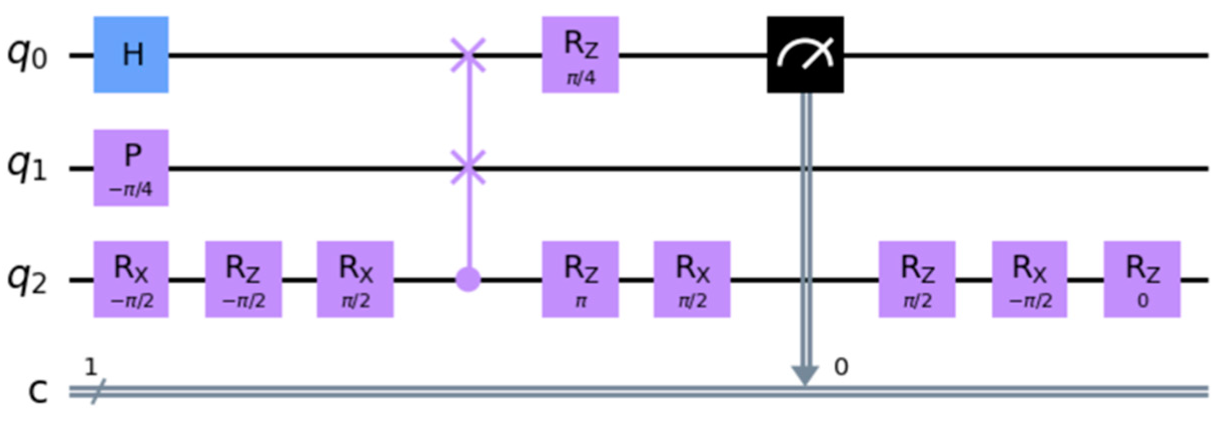
Then, a quantum circuit is built. The circuit uses three qubits and one classical bit. The initial state is a superposition of |0〉 and |1〉 on the first qubit, generated using the Hadamard gate [21]. The circuit then applies a sequence of quantum gates to generate the state |psi〉. The QFT algorithm is now used to solve this system of linear equations. A quantum circuit is created with the number of qubits corresponding to the number of unknowns in the system of equations. Each qubit corresponds to one unknown. Then, the universal gates and cswap operations that make up the QFT algorithm are applied and the last qubit is measured to obtain the result as a classical bit. The quantum circuit can be seen in Figure 2.
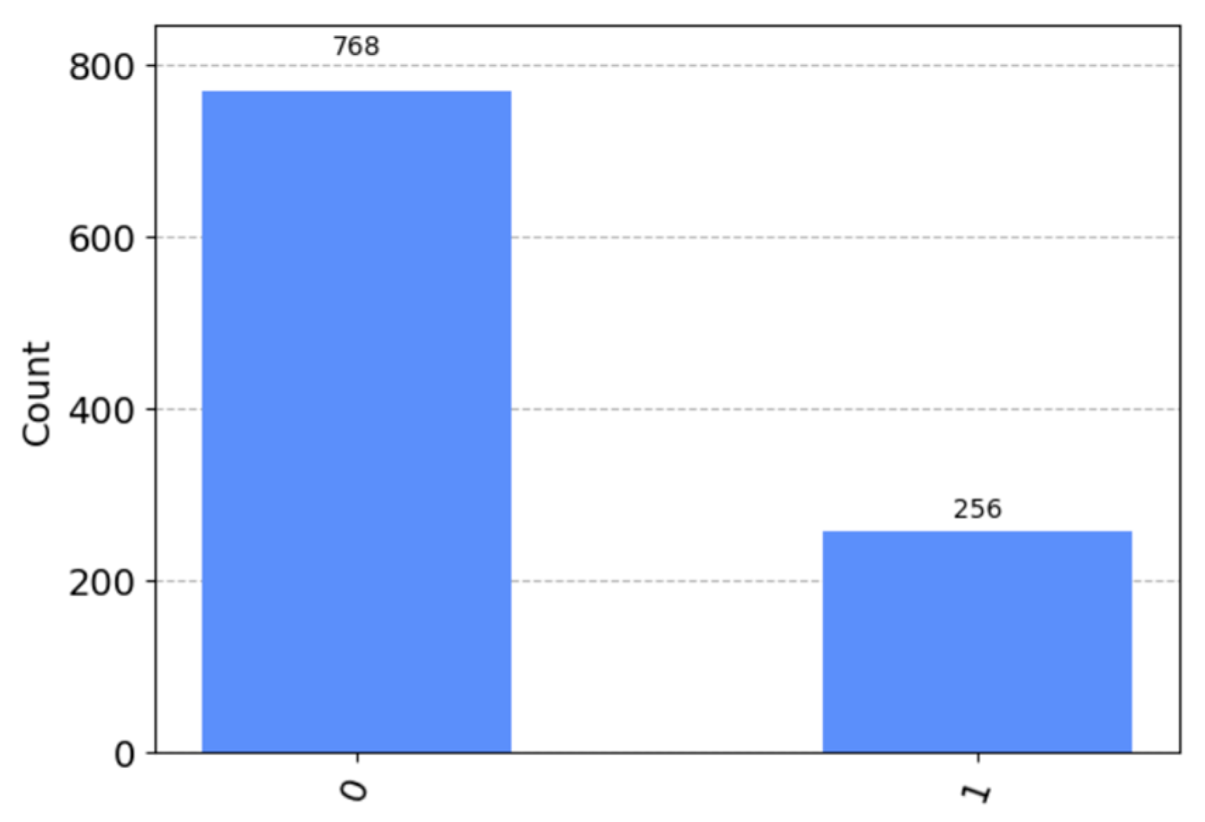
Then, the probabilistic amplitudes are calculated for all states resulting from the execution of the quantum circuit. The circuit is executed on a quantum simulator with a step count of 1024. A three-qubit QASM quantum simulator was used for these calculations of quantum measurement numbers.
In Figure 3, the number of measurements where the quantum computer returned 0 and 1 is calculated. The number of measurements contains information about how many times each bit was measured in the 0 and 1 states, assuming that in some cases the measurements are not deterministic, and the results are not accurate. The state of the quantum system that corresponds most closely (with the greatest amplitude) to the solution of the equation Ax = b is computed.
The simulation results are used to calculate the |psi〉 state, which is a close approximation to the linear system solution. Finally, the system of linear Equation (5) is solved using probabilistic amplitudes and the inverse matrix A.
It is assumed that matrix A is Hermitian [22] and positive definite. If A is not positive definite, the HHL algorithm may not work correctly. The specific mathematical transformations, operations, and algorithms used in the HHL approach are well explained in the work of M. Zhang et al. [23].

2.4. Using the HHL Algorithm on the Poisson Equation

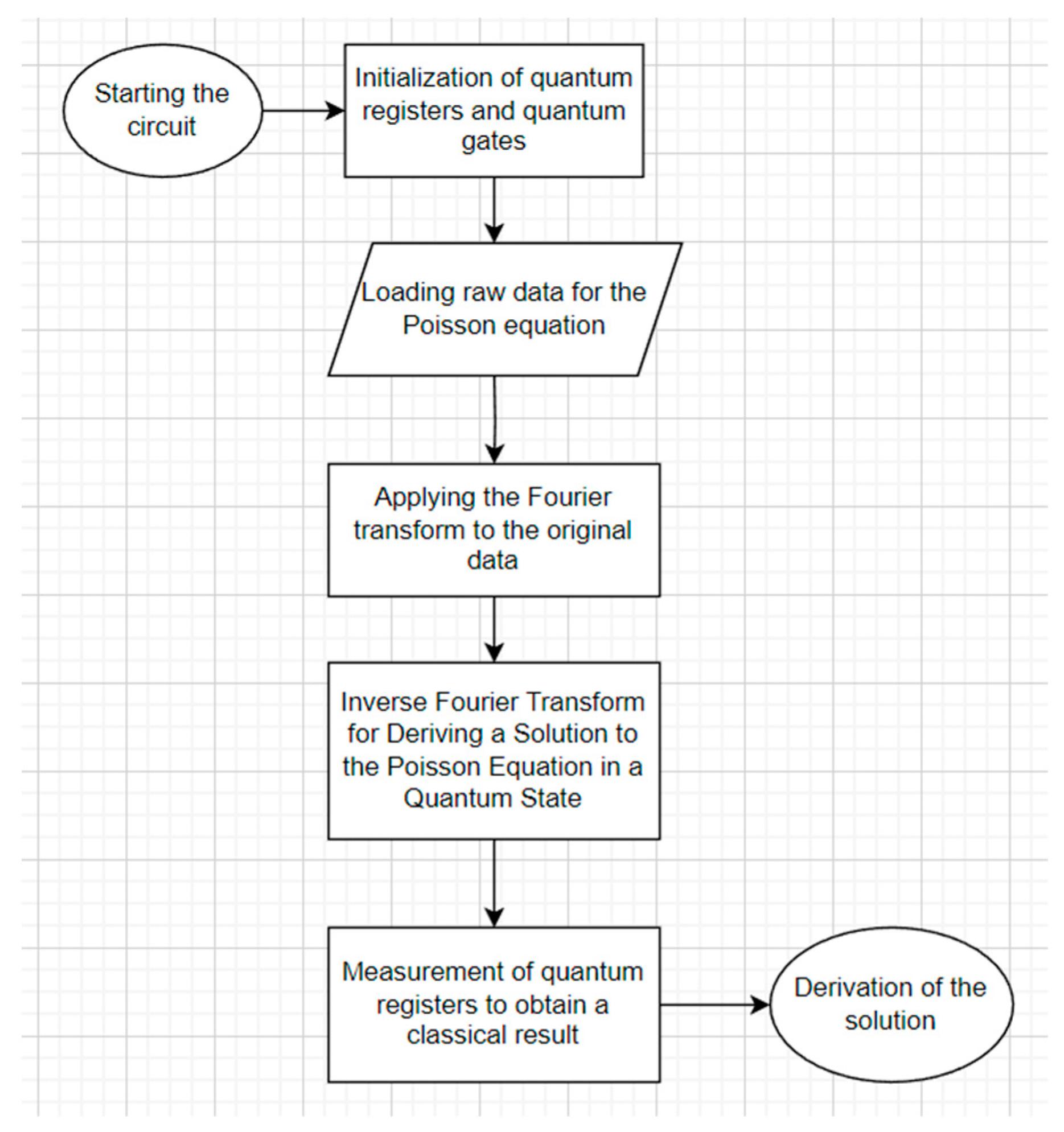
The main idea of this article is to use HHL to solve the Poisson equation. For this, the following steps are implemented:
  • The right-hand-side vector b is represented as a superposition of two states |0〉 and |1〉 proportional to it, i.e., |b〉 = sqrt(p0)|0〉 + sqrt(p1)|1〉;
  • An operator is applied that effectively implements the action of the matrix A on the state |1〉, i.e., |1〉 → |A〉|1〉, where |A〉 is some state that encodes the matrix A;
  • The quantum Fourier transform (QFT) is performed on the qubits corresponding to the right-hand-side vector and matrix A;
  • The qubit corresponding to the right-side vector is measured. In this case, it is the probability of getting 0 or 1;
  • Inverse QFT (IQFT) is applied on all qubits to obtain the inverse Fourier transform for the state |y〉;
  • The first N qubits are measured on the standard basis and the output results are obtained. Then, using the results of measurements and the IQFT, an estimate of the solution x is obtained;
  • To estimate the accuracy of the solution, the vector b ~ = A × x ~ is calculated, where x ~ is the estimate of the solution x;
  • The norm b b ~ is evaluated to obtain an estimate of the error of the solution.
To use the HHL algorithm to solve the Poisson equation, it is necessary to replace the quantum circuit with the number of qubits corresponding to the number of unknowns in the system of equations. Each qubit corresponds to one unknown. For a 2D Poisson equation, it is necessary to create a quantum circuit with N2 qubits, where N represents the number of points on the grid in each dimension. The stages of solving and creating a quantum circuit are shown in Figure 4.
The general idea of the algorithm is as follows, and each part will be analyzed separately. First, the right-hand-side vector b is represented as a superposition of two states |0〉 and |1〉 proportional to it, i.e., |b= sqrt(p0)|0〉 + sqrt(p1)|1〉. This step is to represent the vector on the right side of the equation as a superposition of two quantum states. To do this, the principle of superposition is used, according to which each possible state of a quantum system can be expressed as a linear combination of two basic states, for example, |0〉 and |1〉. In this case, the right vector b is represented as a superposition of states |0〉 and |1〉 proportional to it with weights sqrt(p0) and sqrt(p1), respectively. That is, the vector b is represented as a combination of two states, each state corresponds to one of the possible values of the elements of the vector b (0 or 1), and the weight of this state is determined by the probability of the occurrence of this value of the element of the vector b in solving the equation.
Then, an operator is applied that effectively implements the action of the matrix A on the state |1〉, i.e., |1〉 |A〉|1〉, where |A〉 is some state that encodes the matrix A. In linear quantum algebra, there is the concept of a quantum state, which can be represented as a vector in Hilbert space. In this case, the state |1〉 denotes a qubit that is in the unit state. Matrix A is a matrix that describes the linear transformation of the system that relates the input vector to the output. The operator applied in this step is a controlled unitary operator acting on two qubits: the first qubit is in the state |1〉, and the second qubit corresponds to the matrix element A. The operator |A〉U is needed to apply the matrix A only when the first qubit is in the state |1〉. If the first qubit is in the state |0〉, then the second qubit remains in the same state. Thus, using this operator, one can effectively apply the matrix A to the state |1〉, resulting in the state |A〉|1〉. As a result of this step, the state of the system is described by the vector |A〉|1〉, where |A〉 is some quantum vector encoding the matrix A.
After these steps, the quantum circuit looks like the one shown in Figure 5.
Then, the QFT is performed on the qubits corresponding to the vector and matrix A on the right side. In this step, the transfer is performed, which allows us to transfer the states of the qubits corresponding to the vector on the right side and the matrix A from the measurement basis (for which measurements are obtained in the previous stages) to a basis that allows us to observe something like the eigenvalues of the matrix A and the right side of Equation (5). In quantum computing, the states of qubits are represented as a superposition of states, where each state represents one of the possible values that can be obtained by measuring the qubit. Thus, when a qubit is measured, different values are obtained with a certain probability depending on the state of the qubit.
However, using the Fourier transform, one can transfer the states of qubits to another basis, to the Fourier basis. On this basis, the states of the qubits are represented by superpositions, where each state represents one of the possible values of the “frequency”. This base represents the “eigenvalues” of the matrix A and the vector b, which constitute the solution to Equation (5). So, using the QFT, the results of measurements of qubits in the Fourier basis are obtained, where there are “frequency” values of the matrix A and vector b, and the measurement operation is applied to obtain a solution to the equation. To achieve this, the Hadamard transform is used.
The Hadamard transform is one of the fundamental transforms in quantum computing and it is widely used in various quantum algorithms. In particular, the Hadamard transform can be used to solve the Poisson equation on a quantum computer. The Hadamard transform is applied to a state of n qubits and transforms it into a superposition of all possible states |x〉, where x is a binary representation of a number from 0 to 2n−1. Mathematically, this can be expressed as follows:
H n 0 = 2 n 1 x = 0 2 n 1 x
The next step is to measure the qubit corresponding to the vector on the right. In this case, it is the probability of obtaining 0 or 1. This step applies the measurement operation to the first qubit in the quantum circuit. This means that the first qubit is measured, and the result is a classical bit, which can be either 0 or 1. When the first qubit is measured, the wave function of the system “collapses” into one of two ground states: |0〉 or |1〉. The first qubit is measured to determine how close the state vector of the quantum system, which is the right-hand side of the equation, is to the |0〉 basis vector. If a measurement result of 0 is obtained, this means that the state vector of the quantum system is closer to |0〉, and if a measurement result of 1 is obtained, this means that the state vector of the quantum system is closer by |1〉. Thus, the probability of obtaining a result of 0 or 1 when measuring the first qubit depends on how close the right side of the equation is to |0〉 or |1〉. The closer the right side is to |0〉, the higher the probability is of obtaining the result 0, and the closer the right side is to |1〉, the higher the probability is of obtaining the result 1.
The implementation of the quantum circuit was performed using Qiskit (https://qiskit.org/, accessed on 12 September 2023). Since it was not possible to obtain access to a real quantum computer for testing and running the circuit, quantum simulators were utilized instead.
To obtain the result, one needs to apply the inverse QFT (IQFT) to all qubits of the quantum circuit in order to obtain the quantum Fourier transform for the state |y〉. In the algorithm for solving the Poisson equation using the QFT, it is necessary to apply the IQFT to the quantum state obtained as a result of the Fourier transform in the previous step. The Fourier transform and its inverse are used to change the representation of numbers from one base to another. In the context of quantum computing, the QFT is defined by
F ( x ) = ( N 1 ) y = 0 N 1 e 2 π i x y N y
where |x〉 is the quantum state to be transformed, |y〉 is the quantum state in the new basis, and N is the number of qubits in the register.
The IQFT is defined as
F 1 ( y ) = ( N 1 ) y = 0 N 1 e ( 2 π i x y N ) x
The IQFT is applied to the quantum state that results from the Fourier transform in the previous step to return that state to its original representation. When using QFT to solve the Poisson equation on a quantum computer, the IQFT is used to measure the computation’s result in a new basis, where the solution to the Poisson equation is represented by the most probable state.
After these steps, the quantum circuit is as follows (Figure 6).
After applying the IQFT to the measurement results, the state of the qubits is obtained, which depends on the value of solution x. This state can be expressed as a sum of basis vectors, where the weight of each vector is determined by the corresponding Fourier coefficient. Then, this state is measured on a standard basis to obtain one of the possible vectors. The result is an estimate of the solution x, which is a linear combination of basis vectors whose weights are determined by the Fourier coefficients. This score can be used to evaluate the accuracy of the solution.
Then, it is necessary to evaluate the accuracy of the algorithm. To estimate the accuracy of the solution, vector b = A × x will be calculated, where x is the estimate of the solution x. However, in practice, the matrix A may be poorly conditioned, and significant changes in the vector may lead to large changes in the solution of x. In this case, the resulting solution may be inaccurate or unstable. To evaluate the accuracy of the resulting solution, the vector b ~ is calculated by multiplying the matrix A by the vector x ~ , which is our estimate of the solution x. If the vectors b and b ~ are close, then our estimate of the solution is accurate. If the vectors are very different, our estimate may not be accurate, and additional iterations of the algorithm must be performed to improve the accuracy of the solution. To calculate the vector b ~ , another quantum register is created and operators corresponding to the matrix A are applied to it.
The last step of the algorithm is to estimate the b b ~ norm to obtain an estimate of the error in the solution. The error of the solution is determined here by calculating the norm of the difference between the vector on the right side of the original equation b and the vector on the right side of the modified equation b ~ . To measure the norm of this difference, a quantum phase estimation algorithm is used, which allows, up to a certain constant, to obtain an estimate of the eigenvalue of the matrix M = (I − 2p|bb)U, where U is an operator that implements the modified equation.
Applying the operator U to the psi state, the following form will be obtained:
U ψ = ( N 1 ) j = 0 N 1 ( 1 ) ( b j x j )
where N is the number of qubit states and |xj〉 are qubit states representing all possible bit combinations. Next, the M operator is applied to this state:
M U ψ = ( N 1 ) j = 0 N 1 ( 1 ) b j ( 1 2 p b b ) x j
and then the quantum Fourier transform is applied to this state:
Q F T ( M U ψ ) = ( N 1 ) k = 0 N 1 ( λ k ϕ k )
where |ϕk〉 are the eigenstates of the operator MU and λk are the corresponding eigenvalues. The eigenvalues of the operator MU are equal to −1 for all eigenvectors |ϕk〉 corresponding to states |xj〉 with bj = 0, and 1 − 2p for all eigenvectors |ϕk〉 corresponding to states |xj〉 with bj = 1, where p is the probability of measuring the state |b = 1〉 in the modified equation. Thus, it will be possible to estimate p by measuring the quantum state of QFT(MU|ψ〉) and applying the IQFT to it.

3. Results

3.1. Quantum Scheme and Probabilities for States

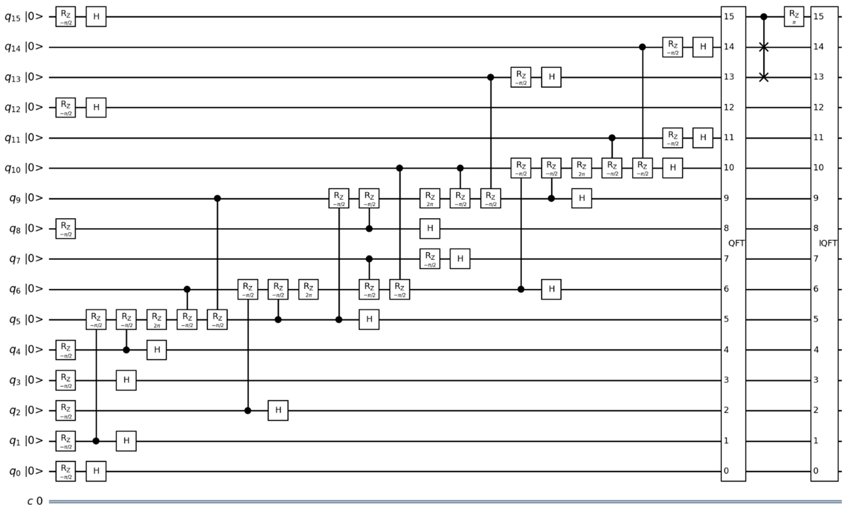
Quantum operations, such as rotations, quantum gates, and measurements, are applied to qubits to change and study their states. After applying all the described steps, qubits are obtained in certain states, which are called eigenstates. To define these states, the final quantum circuit looks like this.
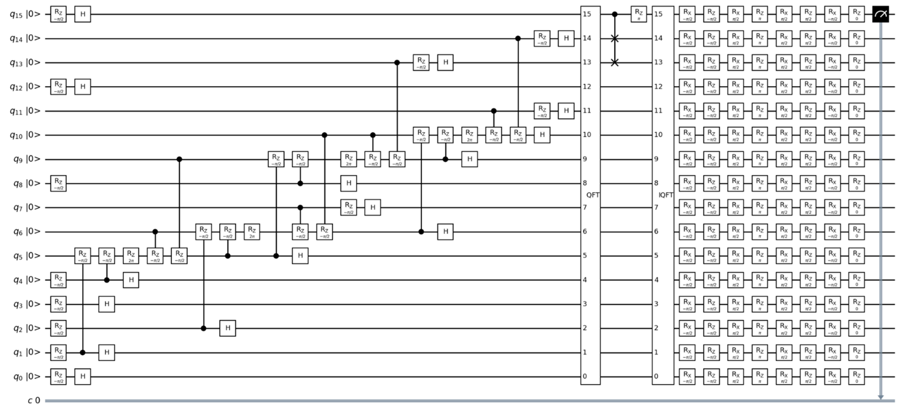
Quantum gates and operations applied to quantum qubits are used to construct all quantum circuits shown in Figure 2, Figure 5, Figure 6 and Figure 7, which are written on IBM Quantum Lab. Once these quantum circuits are created, these circuits will run in quantum simulators.
This quantum circuit performs a sequence of operations on N × N qubits and one classical bit. Let us take a look at its overview:
  • A quantum circuit is created with N × N qubits and one classical bit.
  • The gates associated with matrix A are applied. Each non-zero element of matrix A leads to the application of the corresponding gates. If the element is on the main diagonal (i = j), the rz gate is used. Otherwise, when the element is off the main diagonal (i! = j), the CRZ gate is used.
  • The Hadamard h gate is applied to all qubits.
  • QFT quantum Fourier transform is applied on all qubits.
  • cswap gate is applied between certain qubits.
  • gates rz and rx with defined angles are applied on each qubit.
  • The last rz valve with an angle of 0 can be omitted because it is equivalent to the identity valve.
  • The last qubit is measured, and the result is stored in the classic bit.
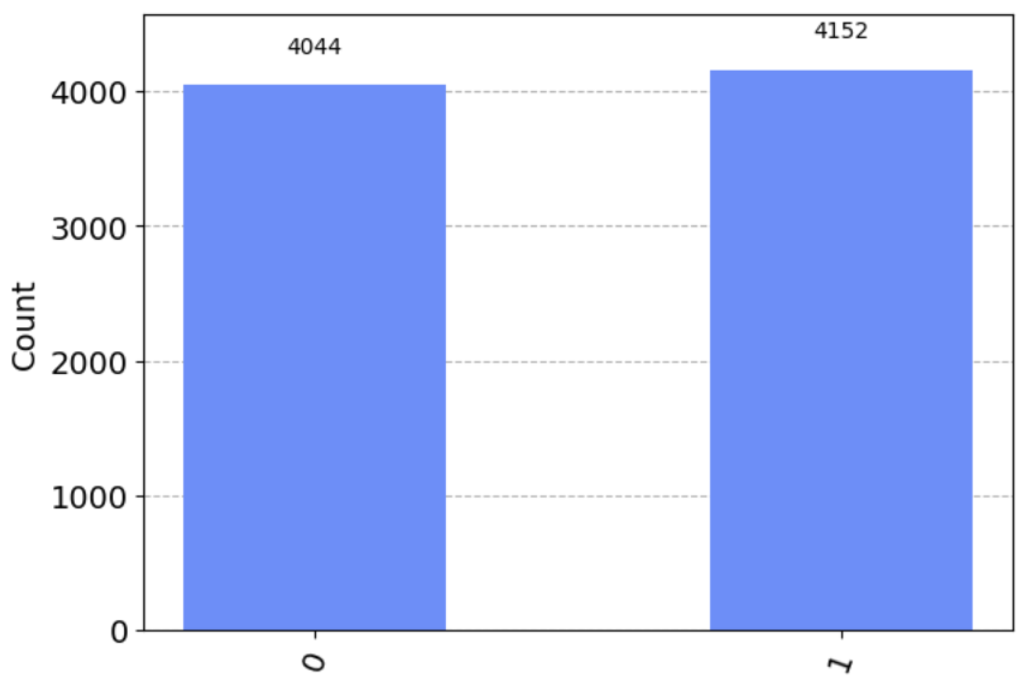
In quantum computing, calculations are probabilistic in nature, and the results of an experiment can change from run to run. To obtain more accurate results, it is necessary to perform several repetitions of the experiment (measurements) and average the results. The “shots” parameter specifies the number of iterations to perform this calculation. In this case, the equations are run 8196 times to obtain reasonably accurate results. The more runs, the more accurate the results, but the more time it takes to calculate. For these calculations, a quantum simulator AerSimulator (https://qiskit.org/ecosystem/aer/stubs/qiskit_aer.AerSimulator.html, accessed on 12 September 2023) with 16 qubits is used. The results are shown in Figure 8.
Then, applying the measurement to the last qubit, one obtains the result for the classical bit.

3.2. Error Calculations in Different Quantum Simulators and in Different Qubits

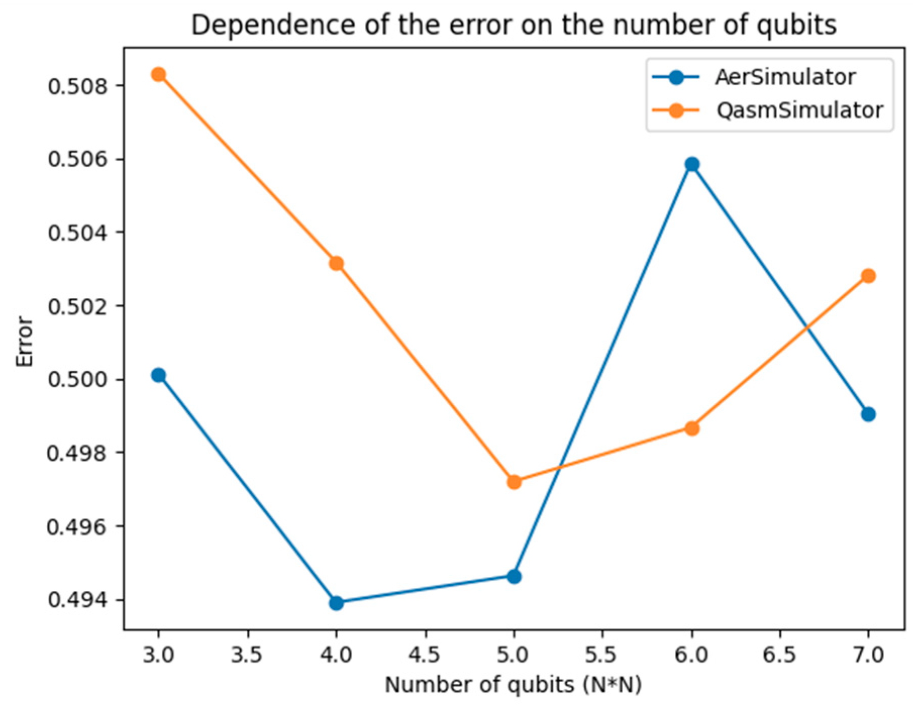
Then, the error is found in different qubits. To estimate the error of the solution of the Poisson equation, this algorithm uses the norm b b where b is the original vector and b is the vector obtained by multiplying the matrix A by the estimate of the solution x . (Figure 9).
The error estimation in the HHL algorithm is performed by comparing the initial vector b with the vector b obtained by multiplying matrix A by the solution estimate x . The difference between these vectors is measured using the norm b b . The error rate can be defined as the ratio of the norm of the difference b b to the norm of vector b. Thus, the results of applying the HHL algorithm to solve the Poisson equation in terms of error rate depend on several factors, including the number of repeated measurements (shots) and the approximation accuracy of the solution. Increasing the number of repeated measurements usually improves the accuracy of the results and reduces the error rate. However, limitations of quantum computing, such as quantum noise and errors in quantum operations, can limit the achievable solution accuracy and affect the error rate.
The error estimate is presented in qubits and has a result of approximately 0.508. Considering the limitations of quantum computing, the result can be considered satisfactory.
Now, let us consider the performance of the algorithm. The execution time of the quantum part of the algorithm depends on the number of qubits, and, in this case, N*N qubits are used. The execution time of the classical part of the algorithm depends on the number of iterations, and, in this case, eight iterations are performed. On a local simulator, the execution time of the quantum part of the algorithm is approximately 0.66 s, and the execution time of the classical part of the algorithm is approximately 10−3 s. This value emerged when the matrix was of a small size. If it is possible to increase the size of the matrix, then quantum simulators freeze and cannot cope with this load.
The execution time of the full code on different simulators is shown in Table 1.
This quantum circuit was designed for N × N matrices, allowing it to run on four-qubit systems. All calculations were carried out using quantum simulators, and this scheme can also be performed on real quantum computers from IBM. Below is a comparison table of computing times between quantum simulators and real quantum computers. Table 2 shows the execution time in quantum simulators and various quantum computers from IBM.
The table results show that the quantum simulators are faster than the real quantum computers ibmq_quito and ibmq_belem for the HHL algorithm. This could have several explanations:
  • Problem size: The table shows that the HHL algorithm uses only 5 qubits on real quantum computers and 63 qubits on a quantum simulator. If the problem scales with increasing numbers of qubits, real quantum computers may begin to show their advantages.
  • Noise and decoherence: Real quantum computers are subject to noise and decoherence, which can slow down the execution of algorithms. Simulators can bypass this limitation because they do not encounter the real physics and noise associated with real quantum systems. If the matrix size is increased, the number of qubits may not be sufficient to run it on real quantum computers. Therefore, the results of work in quantum simulators are obtained faster than on real quantum computers.
The execution time depends on the type of simulator and the size of matrix A. Finally, one can use the estimated decision error to determine the required accuracy of the algorithm and repeat the process with a new value of k until the desired accuracy is achieved.

4. Discussion

This paper presented a study on solving the Poisson equation on a two-dimensional grid using a quantum algorithm. The results of the study have the potential to be generalized to other problems where efficient computation of the solution to this equation is required. The modified HHL algorithm using CRZ rotations is a promising approach to solve such problems.
Comparison of this study with previous works revealed the advantages of the modified HHL algorithm. It has quantum parallelization, which can lead to faster computations compared with iterative classical methods. In addition, this algorithm reduces the amount of memory required and is independent of the mesh dimension, making it more universal.
Despite its advantages, it is worth noting some limitations of quantum computing, such as the need for a large number of qubits to solve large problems and the dependence on certain assumptions about the matrix A. These limitations can affect the performance of the algorithm in some cases.
Practical applications of this research include solving problems in physics, engineering, and computer modeling where an efficient solution of the Poisson equation is required. Improved efficiency and memory savings make the quantum solution more attractive for such applications.
For further practical implementation, it is recommended to continue research in the field of quantum algorithms for solving the Poisson equation. It is important to explore the possibilities of optimizing and improving the modified HHL algorithm, and also to consider applying this algorithm on powerful quantum systems, such as Osprey and Eagle from IBM Quantum, to solve real-world problems with large volumes of data.

5. Conclusions

In conclusion, the results obtained in this paper allow us to assert that the use of quantum algorithms, particularly the HHL algorithm, is effective for solving the two-dimensional Poisson equation. Traditional methods for solving the two-dimensional Poisson equation often require significant computational resources and encounter issues when dealing with grid size expansion. A new approach based on quantum computers uses the properties of quantum mechanics, such as the superposition of states and parallel operations, to effectively solve these problems.
This article considers in detail the problems associated with solving the Poisson equation on a grid using classical methods, emphasizing the computational complexity and resource intensity of these approaches. It discusses the limitations of analytical solutions and the necessity of numerical methods in practical scenarios. The utilization of the HHL algorithm to assess the suggested approach showcases the capability of quantum algorithms to effectively solve the Poisson equation on a 2D grid. The modified version of the HHL algorithm presented in this article, which uses CRZ rotations, offers a reduction in the number of qubits and gates required in the circuit.
The error estimation, expressed in qubits, yields an approximate value of 0.508, which can be deemed acceptable given the constraints of quantum computing. When running on a local simulator, the quantum portion of the algorithm takes roughly 0.66 s to execute, while the classical part only requires approximately 10−3 s. These execution times were observed when working with a small matrix size. To achieve favorable outcomes, it is essential to have the capability to utilize quantum computers and conduct tests on them.
In the future, there are plans to develop a quantum computing algorithm for the problem of fluid flow in the near-wellbore zone of the formation.

Author Contributions

Conceptualization, T.I.; Software, A.M.; Supervision, B.D. All authors have read and agreed to the published version of the manuscript.

Funding

The research is funded by a grant from the Science Committee of the Ministry of Education and Science of the Republic of Kazakhstan under the project number AP09260564.

Institutional Review Board Statement

Not applicable.

Informed Consent Statement

Not applicable.

Data Availability Statement

Not applicable.

Conflicts of Interest

The authors declare no conflict of interest.

References

  1. Cao, Y.; Papageorgiou, A.; Petras, I.; Traub, J.; Kais, S. Quantum algorithm and circuit design solving the Poisson equation. New J. Phys. 2013, 15, 013021. [Google Scholar] [CrossRef]
  2. Dervovic, D.; Herbster, M.; Mountney, P.; Severini, S.; Usher, N.; Wossnig, L. Quantum linear systems algorithms: A primer (Version 1). arXiv 2018, arXiv:1802.0822. [Google Scholar] [CrossRef]
  3. Morrell, H.J.; Wong, H.Y. Study of using Quantum Computer to Solve Poisson Equation in Gate Insulators. In Proceedings of the International Conference on Simulation of Semiconductor Processes and Devices (SISPAD), Dallas, TX, USA, 27–29 September 2021. [Google Scholar]
  4. Childs, A.M.; Liu, J.-P.; Ostrander, A. High-precision quantum algorithms for partial differential equations. Quantum 2020, 5, 574. [Google Scholar] [CrossRef]
  5. Liu, H.-L.; Wu, Y.-S.; Wan, L.-C.; Pan, S.-J.; Qin, S.-J.; Gao, F.; Wen, Q.-Y. Variational quantum algorithm for the Poisson equation. Phys. Rev. A 2021, 104, 022418. [Google Scholar] [CrossRef]
  6. Costa, P.C.S.; Jordan, S.; Ostrander, A. Quantum algorithm for simulating the wave equation. Phys. Rev. A 2019, 99, 012323. [Google Scholar] [CrossRef]
  7. Lloyd, S.; De Palma, G.; Gokler, C.; Kiani, B.; Liu, Z.-W.; Marvian, M.; Tennie, F.; Palmer, T. Quantum algorithm for nonlinear differential equations (Version 2). arXiv 2020, arXiv:2011.06571. [Google Scholar] [CrossRef]
  8. Matsuo, S.; Souma, S. A proposal of quantum computing algorithm to solve Poisson equation for nanoscale devices under Neumann boundary condition. In Solid-State Electronics; Elsevier: Amsterdam, The Netherlands, 2023; Volume 200, p. 108547. [Google Scholar] [CrossRef]
  9. Pesah, A. Quantum Algorithms for Solving Partial Differential Equations; University College London: London, UK, 2020. [Google Scholar]
  10. Engel, A.; Smith, G.; Parker, S.E. Quantum algorithm for the Vlasov equation. Phys. Rev. A 2019, 100, 062315. [Google Scholar] [CrossRef]
  11. Linden, N.; Montanaro, A.; Shao, C. Quantum vs. Classical Algorithms for Solving the Heat Equation. arXiv 2020, arXiv:2004.06516. [Google Scholar] [CrossRef]
  12. Berry, D.W.; Childs, A.M.; Ostrander, A.; Wang, G. Quantum algorithm for linear differential equations with exponentially improved dependence on precision. Commun. Math. Phys. 2017, 356, 1057–1081. [Google Scholar] [CrossRef]
  13. Childs, A.M.; Liu, J.-P. Quantum Spectral Methods for Differential Equations. Commun. Math. Phys. 2020, 375, 1427–1457. [Google Scholar] [CrossRef]
  14. Montanaro, A.; Pallister, S. Quantum algorithms and the finite element method. Phys. Rev. A 2016, 93, 032324. [Google Scholar] [CrossRef]
  15. Gaitan, F. Finding flows of a Navier–Stokes fluid through quantum computing. Npj Quantum Inf. 2020, 6, 61. [Google Scholar] [CrossRef]
  16. Mebrate, B.; Koya, P.R. Numerical Solution of a Two Dimensional Poisson Equation with Dirichlet Boundary Conditions. Am. J. Appl. Math. 2015, 3, 297. [Google Scholar] [CrossRef]
  17. Duan, B.; Yuan, J.; Yu, C.-H.; Huang, J.; Hsieh, C.-Y. A survey on HHL algorithm: From theory to application in quantum machine learning. Phys. Lett. A 2020, 384, 126595. [Google Scholar] [CrossRef]
  18. Liu, X.; Xie, H.; Liu, Z.; Zhao, C. Survey on the Improvement and Application of HHL Algorithm. J. Phys. Conf. Ser. 2022, 2333, 012023. [Google Scholar] [CrossRef]
  19. Camps, D.; Van Beeumen, R.; Yang, C. Quantum Fourier transform revisited. Numer. Linear Algebra Appl. 2020, 28, e2331. [Google Scholar] [CrossRef]
  20. IBM Quantum Lab. Available online: https://lab.quantum-computing.ibm.com/ (accessed on 1 May 2023).
  21. Shepherd, D. On the Role of Hadamard Gates in Quantum Circuits (Version 2). arXiv 2005, arXiv:quant-ph/0508153. [Google Scholar] [CrossRef]
  22. de Bruijn, N. Remarks on Hermitian Matrices. Linear Algebra Appl. 1980, 32, 201–208. [Google Scholar] [CrossRef]
  23. Zhang, M.; Dong, L.; Zeng, Y.; Cao, N. Improved circuit implementation of the HHL algorithm and its simulations on QISKIT. Sci. Rep. 2022, 12, 13287. [Google Scholar] [CrossRef] [PubMed]
Figure 1. A 5 × 5 rectangular grid (black dots represent internal nodes of the grid; white dots represent border nodes).
Applsci 13 11491 g001
Figure 2. Ax = b quantum circuit using the HHL algorithm.
Applsci 13 11491 g002
Figure 3. A number of quantum measurements.
Applsci 13 11491 g003
Figure 4. Block diagram of the solution and creation of a quantum circuit.
Applsci 13 11491 g004
Figure 5. Quantum circuit after converting A and b into quantum states.
Applsci 13 11491 g005
Figure 6. Quantum circuit after application of QFT and IQFT.
Applsci 13 11491 g006
Figure 7. Quantum circuit after measuring the eigenvalues.
Applsci 13 11491 g007
Figure 8. A number of quantum measurements for the HHL algorithm.
Applsci 13 11491 g008
Figure 9. Comparative plot of the error rate in different qubits.
Applsci 13 11491 g009
Table 1. Computation time of the Poisson equation in different simulators.
Quantum SimulatorsTypeTime (s)
qasm_simulatorGeneral51.353
ibmq_qasm_simulatorGeneral, context aware24.219
statevector_simulatorSchrödinger wavefunction5.745
matrix_product_stateExtended Clifford0.6654
Table 2. Execution time in quantum simulators and various quantum computers.
Quantum ResourcesNumber of QubitsTime (s)
simulator_extended_stabilizer630.7246
ibmq_quito54.7431
ibmq_belem55.0169
Disclaimer/Publisher’s Note: The statements, opinions and data contained in all publications are solely those of the individual author(s) and contributor(s) and not of MDPI and/or the editor(s). MDPI and/or the editor(s) disclaim responsibility for any injury to people or property resulting from any ideas, methods, instructions or products referred to in the content.