3.1. Automatic Code Generation to Create a Task
In order to implement this process effectively and efficiently, components such as stored procedure patterns, JS functions for plug-ins, HTML patterns, JSON schema, and the T4 Template library must be readily available. In addition, these components include libraries, templates, plug-ins, and other HTML view patterns. These components are open-source code written in a standardized way that conforms to standard form elements.
The functionality of the patterns encompasses components such as Plugin JS, HTML templates, stored procedures, and JSON schema. Plugin JS allows users to interact with JavaScript code that manages certain web features. HTML templates define the visual presentation of web page elements. JSON schema is a data structure that determines how data are stored and processed. These components can make the software development process faster and easier. They are also customizable and can be adjusted by developers to suit the project’s specifics. HTML plugins and plugins are available, including ready-made JavaScript functions for each HTML element. Some examples of plugins are given in
Table 1.
Figure 3 shows the database schema used for automatic code generation. This database structure defines the main tables of Module, Plugin, Element, Function, Action, and Entity. Establishing relationships between these main tables is undertaken by tables defined with the suffix “Map”, for example, PluginFunctionMap and FunctionElementMap. However, tables with the word “type” in their name represent properties or values associated with the respective parent tables. In database management systems, the automatic generation of CRUD (Create, Read, Update, Delete) operations that carry out essential data operations provides efficiency gains in software development. Using ready-made stored procedure templates facilitates these automatic code-generation processes in this context. Ready-stored procedure templates are given in
Figure 4.
When the automatic code generation infrastructure is prepared, the first step is to add database tables for code generation. The table shown in
Figure 5 has “Column Name, Data Type, and Allow Empty Values” columns. For example, in the “Leave” table, leave start date, leave end date, and description parameters are defined under “Column Name”. The relevant data types for these parameters are specified in the “Data Type” column. The “Allow Empty Values” column indicates whether specific fields are mandatory.
In the second stage, the automatic code generation process starts when the developer creates a data table. Based on the table name, the program automatically executes standard stored procedures. In this process, the development efficiency is increased by using predefined stored procedures. The pseudo-code below defines a connection string based on a specified service name, initializes database connections, and classifies tables according to specific criteria. This code generates SQL procedures for CRUD (Create, Read, Update, Delete) operations and specific procedures for specific tables. These procedures are automatically stored or updated in the database.
In the framework of this work, a stored procedure pattern specific to the Create operation is presented in Algorithm 1. This function creates a stored procedure that performs a Create operation for a given table in the database. If the specified procedure already exists, it is removed and redefined. SQL parameters are set based on the table columns, and a record is inserted during creation. The function returns the full text of the created procedure.
The function described in Algorithm 2 is used to manipulate columns in database tables and plays a central role in all stored procedures.
Each table column identifies unique columns, which are determined with the help of function, id, and meta, and then generates SQL parameter sequences based on this information. The generated parameters are combined according to a specified delimiter and returned as a result. The following function creates the specified database table’s “SQL INSERT INTO” procedure. The function defines the required column names and parameters for each table column, excluding unique columns and key columns specified with the help of meta. Based on this information, the function creates the “INSERT INTO” and “VALUES” expressions, concatenates them according to a specified delimiter, and returns them as results. The generation of the stored procedure “Create” shown in the example above follows a similar approach for other stored procedures such as “Update”, “Read”, “Select”, and “Delete”. It takes table fields from the database according to a specific pattern and generates the stored procedure according to this pattern. Thanks to the “EXEC” command it contains, it saves the generated stored procedure directly to the database. The table in
Figure 6 presents the details of the stored procedures generated automatically. “SPName” specifies the name of the stored procedure. One of the most critical sections, “SPGenerateScript”, contains the SQL code of the generated stored procedure. Finally, “SpTypeName” defines the type of operation the procedure performs.
| Algorithm 1: Stored procedure generation algorithm |
![Applsci 13 11737 i001]() |
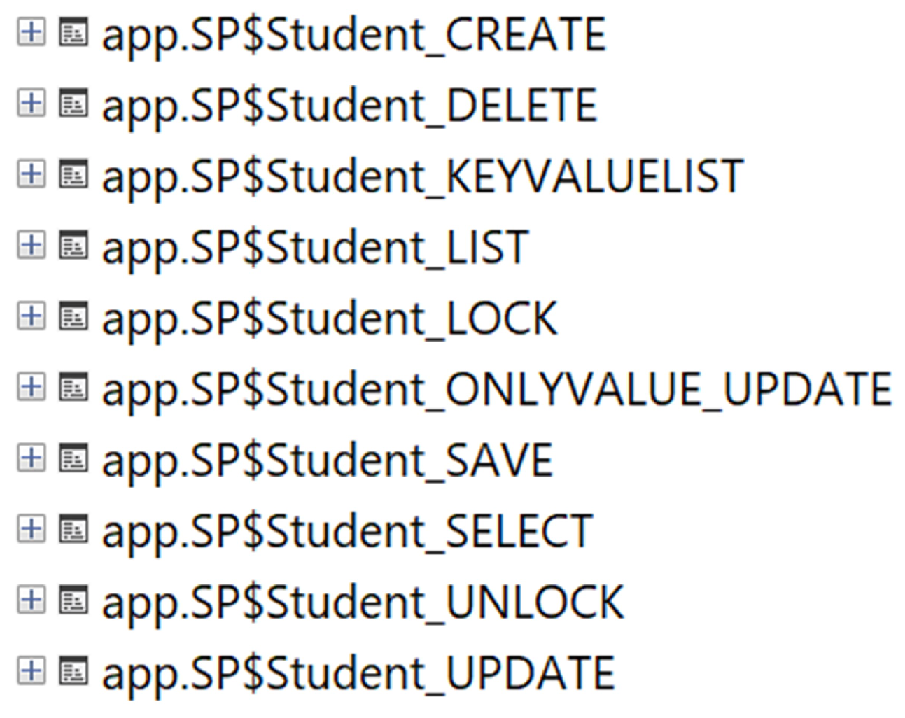
The stored procedures presented in
Figure 7 are automatically added to the database by triggering the “SPGenerateScript” codes in the SPGenerate table. This mechanism provides fast and automatic preparation of the procedures required for CRUD operations.
| Algorithm 2: TransformText |
![Applsci 13 11737 i002]() |
The third step is to save the table created in the database via the Web interface. This process extracts the data, and the appropriate plugins are automatically created. These plugins define the design and functionality of HTML components (buttons, text boxes, etc.) in the user interface. In
Figure 8, database tables are represented in a low-code platform. The rows marked in red color indicate that they have not been registered. The “Register” button at the end of each row allows the relevant record to be made.
During this process, each element’s plugins, actions, and functions are produced separately, and these productions are stored in the database. In the “Element” section, the essential attributes of each column in the database table are determined in detail. Among these attributes, “TypeName”, which defines the column’s data type, and “UITypeName”, which represents the equivalent of this type in the user interface, are particularly prominent.
Based on the ElementDataType table in
Figure 9, default values for a given data type are stored in the Element table (
Figure 10). The purpose of this approach is to systematically save the corresponding data type and default values for each element in the interface in order to be able to generate the corresponding data type for each element.
In
Figure 11, the “Function” section stores the stored procedure names associated with the corresponding database table. The primary purpose of this section is to provide a list of which stored procedures will be triggered as a result of actions performed in the interface. For predefined operations such as Create, Update, and Delete, the relevant stored procedure names are stored in the database in this section.
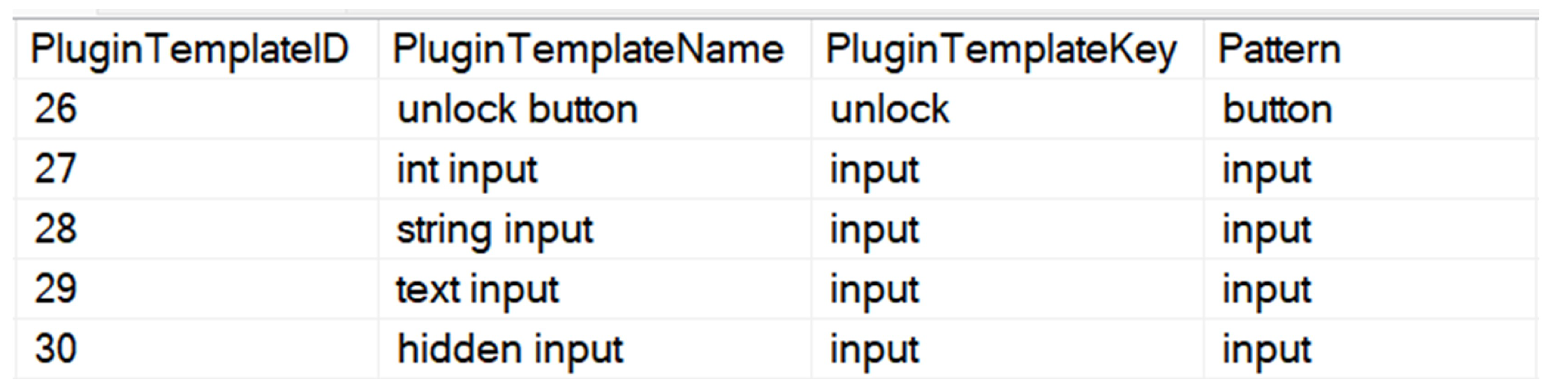
The “Plugin” section in
Figure 12 offers the ability to create plugins for each element in the interface. It supports the creation of forms and the integration of buttons with functions such as “save” and “delete” automatically. Plugins are registered to specific ID values by associating them with the “PluginElementID” value. For example, when the data type in the data table “StudentName” is nvarchar, the appropriate HTML equivalent for this type is defined as “input” in the table “PluginTemplate” (
Figure 13). Based on this information, an automatic plugin record is created. Plugins are prepared based on the predefined “Element” table and then designed for integration with the HTML content in the interface.
The “PluginFunctionMap” table (
Figure 14) performs a critical association task between the “Plugin” and “Function” database tables. This table specifies how each plugin is associated with a particular function, which ensures that actions in the interface are consistently integrated with functions in the backend. A specially designed interface handler called “UICrt” is used for the “Create” operation. This handler is mapped to “FunctionId” to trigger a specific “Function”. Thanks to this mechanism, the records specifying which actions trigger a stored procedure are stored in the “PluginFunctionMap” table.
“Action” (
Figure 15) represents the actions of each plugin in the interface. It includes operations or actions that occur as a result of user interactions.
At the core of the automation process are sophisticated data tables that define production parameters together with business rules. These data tables specify the directions of code generation within the automation, which templates or structural elements are preferred, and what kind of functionality the generated code will realize. In this context, you can find examples of a few tables below.
DefaultModuleWorkerTemplate: Defines the structure with which the module and the worker template are associated. This table provides strategic information about how the code structure of modules should be created.
DefaultPluginAction: Defines the specific actions that plugins will perform. These actions provide critical information about the functionality of the plugin.
DefaultPluginFunctionType: Specifies the function types that plugins will contain. This table provides information about what types of algorithmic functions plugins should have.
DefaultPluginListen: Defines the events that plugins should listen for. This specifies what kind of reaction mechanism the plugin should have in an event-based architecture.
DefaultPluginTemplate: Specifies the basic templates to be used for plugins. This defines which template to reference during code generation.
The functionality and configuration of plugins are often organized around specific templates and rules. In this context, the PluginTemplate and Action tables are an excellent example of this type of configuration.
The PluginTemplate table (
Figure 16) defines the basic templates of plugins. For example, a plugin with a PluginTemplateID value of 1 indicates a form-based structure. A form-based structure is typically used to receive user input and process data. Therefore, it is natural for a form plugin to require specific actions, such as submit, delete, lock, and unlock.
The Action table (
Figure 17) identifies these actions. Each action has a unique ActionID associated with the DefaultPluginAction table (
Figure 18) to determine which plugin template supports which actions. For example, the form template with PluginTemplateID 1 supports actions with ActionIDs 8, 9, 10, and 11.
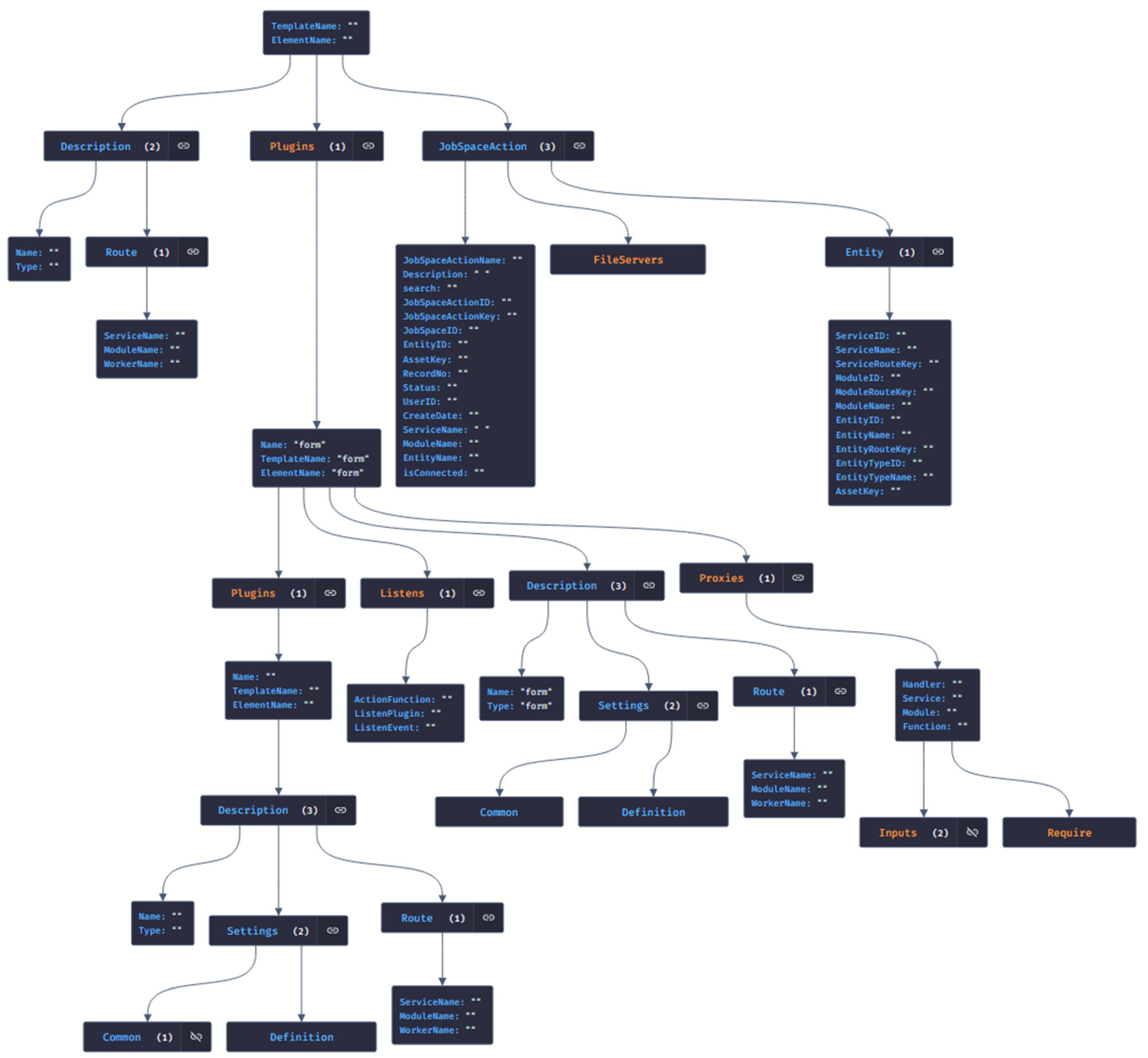
They automatically select the HTML template that best suits the user’s needs based on specific business rules. In particular, when creating a data table, this automation platform automatically selects a form-based HTML template to ensure consistent input data collection. When the data set needs to be listed or queried, another listing-oriented template is preferred to ensure the data are presented appropriately. Workflows defined in the process editor also benefit from this automation. When a conditional workflow is created, the platform automatically adapts an HTML template with functional buttons such as “approved” or “not approved”. In short, these automated code generation platforms select the most appropriate HTML template based on business rules, thus speeding up and standardizing the software development process. Such a structure allows the software to be modular and customizable. It also provides a framework for determining which software components fulfill which functions. This allows the software to have consistency, ease of maintenance, and scalability. In the fourth stage, JSON data modeling was adopted, a popular approach in response to today’s data storage and cross-platform data transfer needs. The JSON generation process, triggered from the web interface through the code generation editor, automatically converts the data in the database into JSON format. As a result of triggering the “Generate JSON” command through the code editor of the low-code platform, the information of essential components such as Element, Plugin, Function, and Action is automatically converted into JSON format. This conversion process is structured through the main sections of the JSON schema, namely Description, Plugins, and JobSpaceAction. The detailed structure of the generated JSON schema is shown in
Figure 19.
In the fifth stage, the JSON conversion performed through the web interface is integrated into the system. The HTML code generation process performs automatic code generation based on JSON data sets. This coding is based on tags that define how the documents interact and how the content (text and images) is positioned. For example, for a button component, the relevant records in the database are automatically mapped to the specified action functions and plug-ins. The HTML template example in Listing illustrates a templating mechanism used in contemporary web applications for dynamic data integration. The corresponding HTML element is decorated with different data-* attributes. The {{ }} constructs inside these attributes represent variable or function calls of the templating language.
| Listing 1. HTML template example for the ‘div’ section of a form-based workflow. |
- 1
<div class=“worker jobspaceaction-form worker-right-side” - 2
data-workertype=“jobspaceaction-form” - 3
data-workerconnections=“{{toJSON WorkerConnections}}” - 4
data-assetkey=“{{this. JobSpaceAction.Entity.Assetkey}}” - 5
data-jobspaceactionid=“{{this. JobSpaceAction.JobSpaceActionID}}” - 6
data-jobspaceactionkey=“{{this. JobSpaceAction.JobSpaceActionkey}}” - 7
data-workername=“{{this.JobSpaceAction.JobSpaceActionName}}”> - 8
</div>
|
The specified HTML segment reflects a typical component of process flow templates. This particular segment is directly associated with the JSON data structure in the Root.JobSpaceAction scope. The “{{ }}” notation used facilitates dynamic data injection, whereby the relevant JSON data elements are automatically injected into the template and blended with the specific information of the process flow. As in Listing 2, these placeholders are replaced with the corresponding values during templating, resulting in flexible and dynamic content.
| Listing 2. Generated HTML code for the “div” section of a form-based workflow. |
- 1
<div class=“worker jobspaceaction-form worker-right-side” data-workertype=“jobspaceaction-form” data-workerconnections=“” data-assetkey=“StudentID” data-jobspaceactionid=“69” data-jobspaceactionkey=“13df19af-26cb-465d-a9f5 - 2
-be2b25ef1244” data-workername=“test”>
|
The specified code examples are parts of a templating mechanism used for dynamic web content generation. The first code segment (Listing 3) reflects the Handlebars.js templating language used to dynamically generate buttons for specific actions by browsing plugins based on a given set of criteria. In particular, this segment creates buttons for the “clear”, “delete”, and “save” types defined within a “form” plugin.
| Listing 3. HTML template example for the “job–action–content” section of a form-based workflow. |
- 1
<div class=“job-action-content”> - 2
<div class=“actions”> - 3
<div class=“form-action”> - 4
{{#each Plugins}} - 5
{{#if_eq this.Description.Name ‘form’}} - 6
{{#each this.Plugins}} - 7
{{#if_eq this.Description. Type ;‘clear’}} - 8
({#button this}} {{/button)} - 9
{{/if_eq}} - 10
{{#if_eq this.Description. Type ‘delete’}} - 11
{{#button this}} {{/button}} - 12
{{/if_eq}} - 13
{{#if_eq this.Description. Type ‘save’}} - 14
{{#button this}} {{/button}} - 15
{{/if_eq}} - 16
{{/each}} - 17
{{/if_eq}} - 18
{{/each}} - 19
</div> - 20
<div class=“job-action”> - 21
<a class=“btn btn-green jobactionlink” - 22
data-key=“{{this.JobSpaceAction.JobSpaceActionkey}}”> - 23
<i class=“fa fa-send-o”></i> - 24
<span data-i18n=“ui:jsallk - 25
{{this.JobSpaceAction.JobSpaceActionID}}”> - 26
{{this.JobSpaceAction. JobSpaceActionName}} Send Request - 27
</span> - 28
</a> - 29
</div>
|
The second code segment (Listing 4) extends this template. Here, static HTML buttons are displayed for specific actions, while the properties and functionality of the buttons are fed with JSON data used in the background. This dynamic data injection allows the quick integration of customized interactive elements into the user interface in a suitable way.
| Listing 4. Generated HTML code for the “job–action–content” section of a form-based workflow. |
- 1
<div class=“job-action-content”> - 2
<div class=“actions”> - 3
<div class=“form-action”> - 4
<button type=“button” class=“btn btn default” - 5
data-plugin=“button” data-type=“clear” - 6
data-plugin-settings=“{‘Common’:{‘color’:‘btn-default’,‘icon’:‘fa-recycle’},‘ Definition’:{}}” data-plugin-listens=“” data-plugin-module=“‘Student’” name=“ Student_clear”> - 7
<i class=“fa fa-recycle”></i> - 8
<span data-i18n=“ui:clear”>Clear</span> - 9
</button> - 10
<button type=“button” class=“btn btn default” - 11
data-plugin=“button” data-type=“delete” - 12
data-plugin-settings=“{‘Common’:{‘color’:‘btn-default’}, ‘Definition’:{}}” - 13
data-plugin-listens=“” data-plugin-module=“‘Student’” name=“Student_delete”> <i class=“fa ”></i> - 14
<span data-i18n=“ui:delete”>Delete</span> - 15
</button> - 16
<button type=“button” class=“btn btn default” - 17
data-plugin=“button” data-type=“save” - 18
data-plugin-settings=“{‘Common’:{‘color’:‘btn-default’}, ‘Definition’:{}}” - 19
data-plugin-listens=“” data-plugin-module=“‘Student’” name “Student_save”> - 20
<i class=“fa ”> </i> - 21
<span data-i18n=“ui:save”>Save</span> - 22
</button> - 23
</div> - 24
<div class=“job-action”> - 25
<a class=“btn btn-green jobactionlink” - 26
data-key=“13df19af-26cb-465d-a9f5-be2b25ef1244”> - 27
<i class=“fa fa-send-o”></i> - 28
<span data-i18n=“ui:jsallk69”>Send Request - 29
</span> - 30
</a> - 31
</div> - 32
</div> - 33
</div>
|
The first code fragment (Listing 5) represents a raw template containing some placeholders. These placeholders are denoted by { } structures and are intended to be filled with JSON data, usually retrieved from a server or generated on the client side.
| Listing 5. HTML template example for the “entity–form” section of a form-based workflow. |
- 1
<div class=“entity-form-content form”> - 2
{{#each Plugins}} - 3
{{#if_eq this.Description.Name ‘form’}} - 4
{{#form this}} {{/form}} - 5
{{/if_eq}} - 6
{{/each}} - 7
</div>
|
When applied in the second code block (Listing 6), the templating process of the generated HTML generates the final HTML form of the dynamic content. In the second block, we see a completed student form. While the form collects information such as the student’s name, certain “handler" functions are used to process and store this information. These functions are defined in the form’s data–plugin–proxies attribute and are used for various operations such as creating, reading, updating, and deleting student information. In addition, the data–plugin–listens attribute is used to specify the functions that should be performed in response to specific events in the form (e.g., saving student information).
Figure 20 reflects an HTML view representing the final result of the automated code generation process. This visualization is a typical example of what an automated web interface can look like. This result is essential for developers and engineers to evaluate the success of automated coding processes.
| Listing 6. Generated HTML code for the “entity–form” section of a form-based workflow |
- 1
<div class=“entity-form-content form”> - 2
<form action=“javascript:void(0)” - 3
data-plugin=“form” - 4
name=“Student_form” - 5
data-plugin-settings=“{‘Common’:{},‘Definition’:{}}” - 6
data-plugin-proxies=“[ - 7
{ - 8
‘Handler’:‘UICrt’, - 9
‘Service’:‘StudentService’, - 10
‘Module’:‘Student’, - 11
‘Function’:‘Create’, - 12
‘Inputs’:[‘StudentName’,‘CreateUserID’], - 13
‘Require’:[] - 14
}, - 15
{ - 16
‘Handler’:‘UISlct’, - 17
‘Service’:‘StudentService’, - 18
‘Module’:‘Student’, - 19
‘Function’:‘Read’, - 20
‘Inputs’:[‘StudentID’], - 21
‘Require’:[] - 22
},{ - 23
‘Handler’:‘UIUpdt’, - 24
‘Service’:‘StudentService’, - 25
‘Module’:‘Student’, - 26
‘Function’:‘Update’, - 27
‘Inputs’:[‘StudentID’,‘StudentName’,‘CreateUserID’], - 28
‘Require’:[]}, - 29
{ - 30
‘Handler’:‘UIDlt’, - 31
‘Service’:‘StudentService’, - 32
‘Module’:‘Student’, - 33
‘Function’:‘Delete’, - 34
‘Inputs’:[‘StudentID’,‘CreateUserID’], - 35
‘Require’:[]}, - 36
{ - 37
‘Handler’:‘UILck’, - 38
‘Service’:‘StudentService’, - 39
‘Module’:‘Student’, - 40
‘Function’:‘Lock’,‘Inputs’:[‘StudentID’], - 41
‘Require’:[] - 42
}, - 43
{ ‘Handler’:‘UIUnLck’, - 44
‘Service’:‘StudentService’, - 45
‘Module’:‘Student’, - 46
‘Function’:‘UnLock’, - 47
‘Inputs’:[‘StudentID’], - 48
‘Require’:[] - 49
}]" - 50
data-plugin-description=“{‘Name’:‘form’,‘Type’:‘form’,‘ Settings’:{‘Common’:{},‘Definition’:{}}, - 51
‘Route’:{‘ServiceName’:‘StudentService’, ‘ModuleName’:‘ Student’, - 52
‘WorkerName’:‘studenttalepformu2_10_09_2023_www’}}” - 53
data-plugin-listens=“[ - 54
{ - 55
‘ActionFunction’:‘lock’, - 56
‘ListenPlugin’:‘lck’, - 57
‘ListenEvent’:‘Student_lck_click’ - 58
}, - 59
{ - 60
‘ActionFunction’:‘unlock’, - 61
‘ListenPlugin’:‘unlock’, - 62
‘ListenEvent’:‘Student_unlock_click’ - 63
}, - 64
{ - 65
‘ActionFunction’:‘submit’, - 66
‘ListenPlugin’:‘save’, - 67
‘ListenEvent’:‘Student_save_click’ - 68
}, - 69
{ - 70
‘ActionFunction’:‘delete’, - 71
‘ListenPlugin’:‘delete’, - 72
‘ListenEvent’:‘Student_delete_click’ - 73
}, - 74
{ - 75
‘ActionFunction’:‘clear’, - 76
‘ListenPlugin’:‘clear’, - 77
‘ListenEvent’:‘Student_clear_click’ - 78
}]” - 79
class=“fixed-height -horizontal form-bordered
form-label-stripped”> - 80
<div class=“form-body”> - 81
<div class=“form-group form-md-line-input ”> - 82
<label for=“StudentName” class=“col-md-3 control-label” data-i18n=“Student:StudentName”>StudentName</label> - 83
<div class=“col-md-9”> - 84
<div class=“input-icon”> - 85
<textarea data-plugin=“input” class=“form-control ” id=“StudentName” name=“StudentName” data-plugin-settings=“{‘Common’:{‘type’:‘ textarea’,‘icon’:‘fa-pencil-square-o ’,‘ icon_type’:‘input’},‘Definition’:{}}” data-plugin-listens=“”></textarea> - 86
<div class=“form-control-focus”></div> <span class=“help-block” data-i18n=“ Student:StudentName_desc”> Student:StudentName_desc</span> <i class=“fa fa-pencil-square-o ”></i> - 87
</div> - 88
</div> - 89
</div> - 90
<input data-plugin=“input” id=“StudentID” type=“hidden” class=“identity-class” name=“StudentID” data-plugin-settings=“{‘Common’:{‘hidden’:‘true’,‘Class ’:‘identity-class’},‘Definition’:{}}” data-plugin-proxies=“” data-plugin-listens=“”> - 91
</div> - 92
</form> - 93
</div>
|
This templating approach illuminates how the data and presentation layer are effectively separated and integrated with dynamic web applications. This methodology significantly facilitates code readability and maintainability while increasing the flexibility of the application. In addition, we observe that dynamic HTML generation is possible in just a few steps by incorporating a manually created database into the low-code platform with the “Register” command and then using the “Generate JSON” and “Generate HTML” commands. This dramatically increases the efficiency and speed of development processes. The integration between the interface and the backend is realized using the RESTful web service. This methodology unlocks the potential of automatically coding existing stored procedures based on database tables. The generated code is compatible with RESTful service protocols. Following the automated coding process, the resulting web service code is compiled, and the DLL file generated due to this compilation must be hosted on the target server. The automation process is presented in the pseudocode below. In this pseudocode, the “Create” and “Update” methods are examples of the web service code pattern (Listing 7). We can observe that the CreateMethodName, MethodReturnType, table name, and model variables are dynamically assigned; these variables are populated based on the corresponding database table, thus enabling automatic code generation.
| Listing 7. Web service code pattern. |
- 1
[Route(“<#=MetaHelp.CreateMethodName #>”)] - 2
[HttpPost] - 3
public <#=MetaHelp.MethodReturnType#> <#=MetaHelp.CreateMethodName #> - 4
(SP_<#=table.Name #>_SELECT_Result model) - 5
{ - 6
return db.SP_<#=table.Name #>_CREATE( - 7
<#=NETHelp.WriteCreateClause(table, “model”) #>).FirstOrDefault(); - 8
} - 9
[Route(“<#=MetaHelp.UpdateMethodName #>”)] - 10
[HttpPut] - 11
public <#=MetaHelp.MethodReturnType#> <#=MetaHelp.UpdateMethodName #> - 12
(SP_<#=table.Name #>_SELECT_Result model) - 13
{ - 14
return db.SP _<#=table.Name #>_UPDATE( - 15
<#=NETHelp.WriteUpdateValues(table, “model”) #>).FirstOrDefault(); - 16
}
|
The automatically generated code of the ASP.NET Web API is essential in data integration. However, it should be noted that this automatic process requires some manual steps. In particular, the DLL obtained after compilation must be manually integrated into the server. This is an indispensable step for efficient data transmission between the client and the backend.
One of the notable advantages of our implementation is the method we have adopted for data exchange. We have fragmented the delivery process rather than delivering all assets in a single monolithic chunk. HTML, CSS, and data are retrieved separately, ensuring swifter loading times. No matter the expansion of our site, each time a webpage is accessed, it necessitates packets of JavaScript, HTML, CSS, and other data. Our pages load with remarkable speed by fetching these assets individually from the server and database. Moreover, our system works with a Content Delivery Network (CDN) methodology. It verifies content versions and sends requests only for the changed assets. While this boosts performance, it is pivotal to recognize that scalability presents its unique challenges, which we tackle using distinct techniques.
In
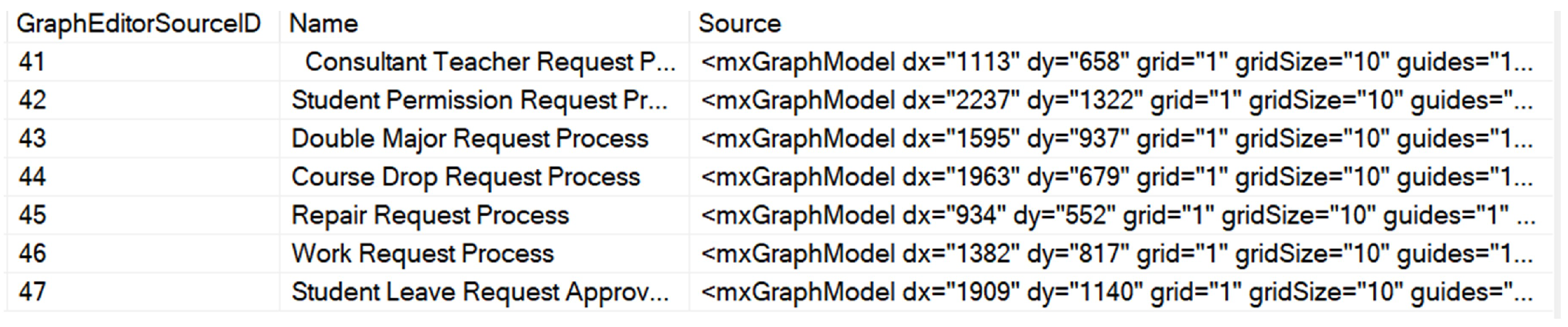
Figure 21, HTML and JSON codes in the Source field in the WorkerContent table are integrated into these low-code platforms to support the dynamic content creation and display process. Regarding the functioning, firstly, code fragments in HTML and JSON format are saved in the specified database. These codes contain the structures and features that the user will use in their applications on the web. These saved code fragments are pulled from the database on demand by the platform and dynamically rendered on the user’s interface. This process enables rapid prototyping, testing, and final release of the application. At the same time, centralized storage of code in a database brings operational advantages such as version control, backup, and deployment. As a result, this integration capability of low-code platforms accelerates application development processes, minimizes errors, and provides users with a more flexible development environment.
3.2. Creating a Workflow Process in a Web Environment
In the implementation of the process, firstly, the tasks are detailed. Then, using the Web Application interface called “Process Design Editor”, the relationship and interaction flow between these tasks are designed. This editor supports drag and drop, providing developers with an essential convenience in dynamically visualizing and editing the process. In
Figure 22, taken as a reference, we can examine how users interact with flowchart flow diagrams to design a business process. Each symbol and flowchart represents a specific functionality or part of a process.
The conditional flow, shown in
Figure 23, enables the workflow to follow different paths as a specific condition is fulfilled. This methodology supports dynamic routing in the workflow based on specific conditions. Binary decision mechanisms typically evaluate the conditions. This fulfills the requirements for branching and merging workflows so that processes become more flexible and allow the flow to be managed accurately.
Single Task Flow, depicted in
Figure 24, is a workflow model in which each task is sequenced based on the completion of the previous one. This model is ideal for simple, low-complexity processes where tasks build on each other and occur sequentially. In this structure, where each task has a specific priority, high efficiency is achieved with the correct sequencing.
The Multi-Task Flow presented in
Figure 25 represents a workflow model in which multiple tasks are performed in parallel. This model emphasizes the independence of tasks within the process so that simultaneous progress is achieved without waiting for each task to complete. This approach is preferred for complex processes where waiting times must be minimized. The creation of the workflow is realized using specific design tools. These tools help place the workflow steps sequentially with “drag and drop” features. Workflow steps represent specific actions, such as sending an e-mail or retrieving data from a database. This process includes the following steps:
The purpose of the workflow is defined.
Specific steps and their dependencies are identified.
A flow diagram is created showing the connections between the steps.
The inputs and outputs of the workflow are defined.
The workflow is validated by testing.
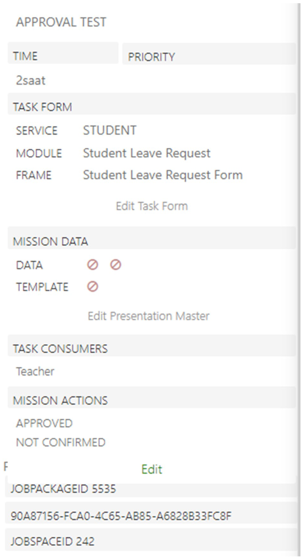
Order reception, processing, dispatch, invoicing, and payment confirmation. These steps proceed with specific inputs and are performed under predefined conditions. In
Figure 26, the process editor has a panel that defines the characteristics of each flow, the associated service module, and the associated data package. The “Task Form” contains information retrieved from the Service and Module databases, while the “Task Actions” correspond to actions in the Flowchart.
Using the same example, the diagram in
Figure 27, the process screen shows the workflow process. In order to make a design, the design is realized by dragging and dropping the elements in the panel in the design editor. An example of a “Leave Request Form” is given in
Figure 27. This means that students are associated with the Leave Request Form module, and the data for each workflow are retrieved from the “Student” database.
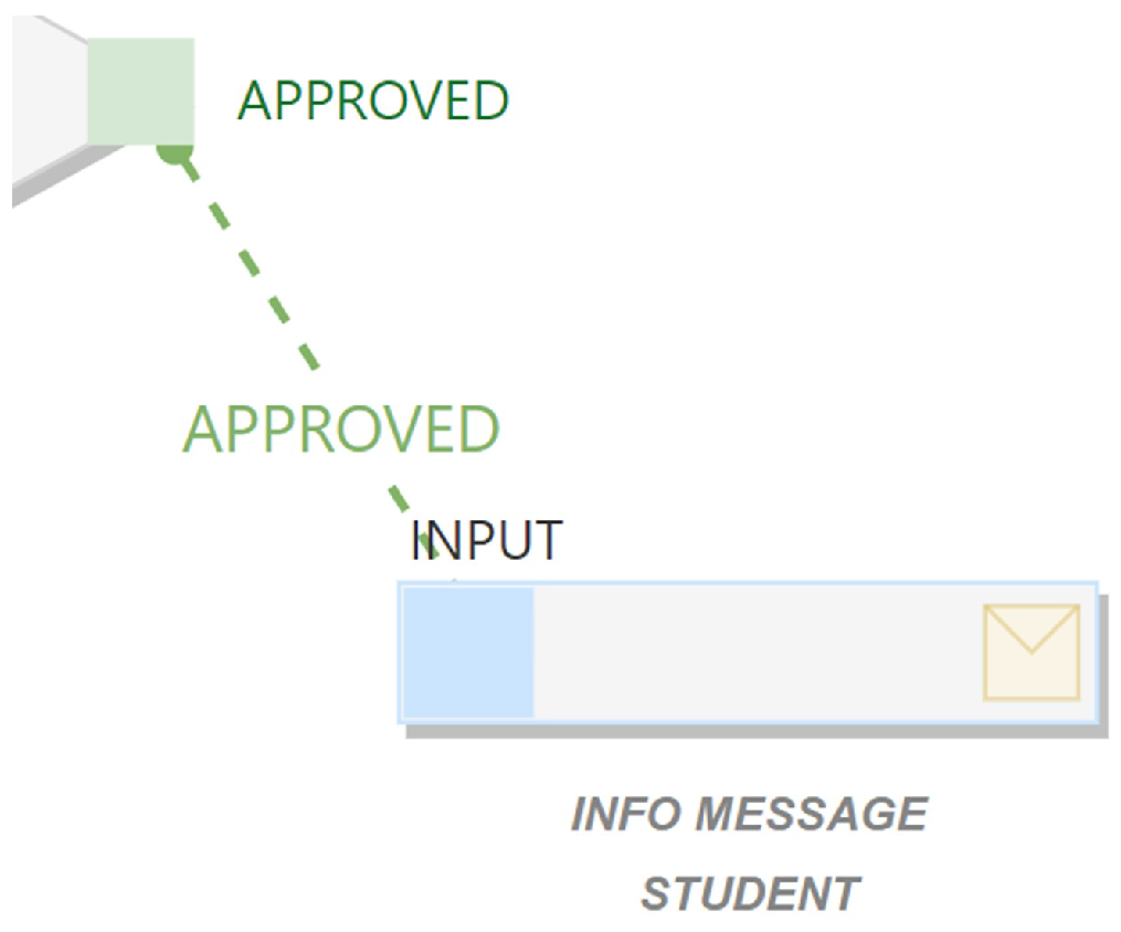
Definitions are made for manually added elements in the panel in the workspace. The completed design is converted to the mxGraph model. mxGraph is a JavaScript library for graphical interface designs and diagrams, enabling the creation of web-based visual models. It is known for its customization and integration capabilities. Listing 8 presents an example converted from workflow to mxGraph model; the “Confirmed” action indicates the next steps.
The coded version of the workflow model shown in
Figure 28 is given in Listing 8. Each workflow element is identified with a unique identification number. The descriptions of the fields in the code example are as follows:
| Listing 8. The mxGraph model of a workflow given in Figure 28. |
- 1
<mxCell - 2
id=“0353db73-9856-4f8b-a4a3-a370c37d1502” - 3
value=“APPROVED” - 4
<mxGeometry x=“1”y=“0.5”width=“23”height=“23”relative=“1” - 5
as=“geometry”> - 6
<mxPoint x=“-20”y=“-12”as=“offset”/> - 7
</mxGeometry> - 8
<JobConnectionDto as=“data”> - 9
{ - 10
“obj”:{ - 11
“AssetKey”:“JobActionID”, - 12
“AssetValue”:1767, - 13
“Connect”:“out”, - 14
“JobSpaceID”:230, - 15
“EventTypeID”:2, - 16
“Title”:“Approved”, - 17
“TitleFull”:“testonay”, - 18
“StyleFormater”:“accept”, - 19
“_”:{ - 20
“JobActionID”:1767, - 21
“JobPackageID”:5521, - 22
“JobActionName”:“Approved”, - 23
“JobActionKey”:“0353db73-9856-4f8b-a4a3-a370c37d1502”, - 24
“IsBaseAction”:true, - 25
“UserID”:“4f7ae81d-96ce-4217-bfef-fd687328ca79”, - 26
“JobPackageName”:“testonay”, - 27
“Durum”:1, - 28
“LogicValue”:1, - 29
“SortOrder”:99 - 30
} - 31
} - 32
} - 33
</JobConnectionDto> - 34
</mxCell>
|
Here are some of the properties for workflow items:
ID: The unique identification number of the items.
Value: The name of the item, such as “Approved”.
AssetKey: The unique identifier of the asset.
JobSpaceID: The ID of the workspace.
EventTypeID: Defined type of the event.
JobActionID: ID of the action.
JobPackageID: Number of the data package to use.
When the user operates, the relevant information is retrieved from the database in real time. With this information, workflow processes are created using the graphical design tool. Finally, the created model is transformed with mxGraph and saved in the database (
Figure 29).
Each flowchart is saved in the database after conversion into a Business Model. The Business Model is essential for automating, coordinating, and scheduling business processes. This model specifies the steps required by the work, the sequence of these steps, the relevant data, and the actions to be performed at each step. This automation allows operations to be performed quickly, efficiently, and without errors. The transformed Business Model is stored and labeled in a separate database. This labeling is critical in defining and guiding complex processes with multiple actions. The automatically generated HTML element contains a fundamental property called “data-jobspaceactionkey”. This key is directly related to the ReflectionEventKey in the database and is called JobActionKey. ReflectionEventID information is retrieved from the database through this specific key when any action is triggered in the user interface. The resulting ID is used with the EntityID to guide further process steps (Listing 9).
| Listing 9. Generated HTML code with the job action key. |
- 1
<div class=“worker jobspaceaction-form worker-right-side” data-workertype=“jobspaceaction-form” data-workerconnections=“” data-assetkey=“StudentID” data-jobspaceactionid=“68” data-jobspaceactionkey=“111a9f99-ecea-42e3-8e2d-51f8ae1e8a67” data-workername=“Student Request Form”>
|
Within the structure in which the processes are defined, the relational data expressing the transitions from one process to another are already stored in the database and are retrieved from this database. This relational data set is stored in the ReflectionEvent table (
Figure 30). In the example, jobspaceactionkey on the HTML side and ReflectionEventKey in the data table are the same.
When switching to the next screen, the required screen information is retrieved through a specific ReflectionEventKey and presented to the user (
Figure 31).
The “ReflectionMap" table is a critical mapping table for centralized management of the automation processes of information systems. The primary function of this table is to determine which process or screen will be activated according to the results of user actions.
ReflectionMapID: Unique identifier of the record.
JobSpaceName: The name of the process space.
SourceJobPackageName: The name of the starting package from which the action is started.
ReflectionEventName: Identifies the triggered event, usually indicating which phase the form is in.
JobPackageName: Indicates which package will be activated after the triggered action.
JobSpaceID: Unique ID of the process space.
EntityID: Indicates the screen or process step to be activated.
ReflectionEventID: The unique ID of the triggered event.
This table is designed to effectively manage the processes corresponding to user actions in the automation process. It determines which process or screen is activated when a user performs a specific action. It also provides a mapping between actions and results, which allows the automation processes within the system to proceed smoothly. This integrated structure allows the system to manage automation processes more efficiently while allowing the user a more fluid and seamless experience. User actions on the screen or form are instantly processed through the RabbitMQ messaging infrastructure. RabbitMQ is frequently used in microservice architectures with its flexible and secure protocols. For example, in an educational institution, the permission form filled out by the student is immediately notified to both the administration and the relevant teachers via RabbitMQ. This process occurs thanks to RabbitMQ’s publish/subscribe model, where messages are usually packaged in JSON or XML format (Listing 10).
| Listing 10. RabbitMQ: publish/subscribe messaging with JSON and XML. |
- 1
data = { - 2
“Name”: “John Smith”, - 3
“permission_type”: “sickleave”, - 4
“start_date”: “2023-04-18”, - 5
“end_date”: “2023-04-25” - 6
}
|
The third step is to send the data packet to a specific queue:
# Specify the queue name and the data packet
queue_name = ‘permission_form’ message = json.dumps(data)
# Send message to queue
channel.basic_publish(exchange=”’, routing_key=queue_name, body=message)
# Close the connection connection.close()
Messages are sent in JSON format to the permission_form queue using the basic_publish function and distributed to connected consumers. This communication is coordinated under the SAGA architecture and state machine. SAGA is an architectural model for microservice-based, autonomous, and decentralized applications. While each microservice runs on its database, the SAGA transaction execution manager ensures data consistency. This manager maintains data integrity when an error occurs by rolling back transactions. This architecture supports the independent development and scaling of microservices. Concurrent interaction is realized through the SignalR framework. The basic steps followed in the process of construction are as follows:
Data Modelling: this is essential to design database structures. The database schema is visualized with the data modeling tools provided by the software used.
Process Definition: tools such as MxGraph are used to design business processes graphically.
Interface Design: the application’s user interface is prepared with the visual interface design module provided by the software.
Determination of Business Rules: rules regarding business logic are defined with the relevant software modules.
Testing and Execution: the prepared process is tested to check its accuracy and functioning.
These steps are carried out with software tools that enable processes to be built effectively.


