
Experimental Investigation of Enhancement of Natural Convective Heat Transfer in Air Using Ultrasound


Institute of Technology and Chemical Engineering, Poznań University of Technology, 60-965 Poznań, Poland
*
Author to whom correspondence should be addressed.
Appl. Sci. 2023, 13(4), 2516; https://doi.org/10.3390/app13042516
Submission received: 6 December 2022
/
Revised: 8 February 2023
/
Accepted: 13 February 2023
/
Published: 15 February 2023
(This article belongs to the Special Issue Thermophysics and Heat Transfer)
Abstract
:One of the methods to improve convective heat exchange is the application of ultrasound assistance. However, little is known about ultrasound application in the air. The main purpose of this study is to investigate the effect of ultrasound on natural convection cooling. The tests are based on the cooling of the metal samples (in four different shapes) preheated to a temperature of 60 °C. Cooling takes place in free convection without and with the use of ultrasound at different powers (50 W, 100 W, 150 W, and 200 W). The study uses a mathematical model based on a small Biot’s number assumption. The values of the convective heat exchange coefficients are determined by using an approximation of the experimental results. The coefficients obtained are an increasing exponential function of the applied ultrasound power. This study indicates the possibility of using ultrasound to improve heat transfer by free convection.
1. Introduction
In the era of the energy crisis, in connection with the introduction of closed-loop technology all over the world, and to protect our natural environment, an important issue is the intensification of heat exchange, including convective exchange. Each improvement of this process may have a positive impact on the environment and bring measurable economic benefits, e.g., by shortening energy-intensive operations, such as drying.
The methods of intensifying convective heat exchange can be divided into passive and active [1]. Passive methods include the use of liquids with enhanced thermal properties [2,3] or a profile with a specially shaped flow geometry [1,4]. In turn, active methods include the use of an external electric field [5], a magnetic field [6], or forcing the flow pulsation of the flow [7].
Passive air cooling of metal components in the air environment is widely used in technology, for example in electric vehicles, which are to dominate the future transport sector where many components, such as inverters, batteries, computers, and drive systems require dedicated cooling systems [8]. Thermal management is also crucial for electronic devices, where excessive heating during the operation of the device results in the most damage. In addition, the modern trend of the miniaturizing of electronic devices with better performance and features further increases the need for a suitable cooling system [9]. Furthermore, high temperature (especially in some environments) significantly affects metal corrosion; therefore, methods are sought to reduce the susceptibility to corrosion [10].
Passive air cooling is also frequently used in the food industry. Thermally processed food products usually need to be cooled for further processing or packaging. Cooling is used, among other things, in the manufacture of soybean products that are produced by the steam cooking of soybeans, then draining the seeds and cooling them to 40 °C and mashing, and then further processing them into a specific product. Furthermore, shapes and molds in the confectionery industry, such as candies and jelly, are made by having heated products deposited in molds to cool and harden. Cooling is also used as a basic step in the production of dried ham as a production step between smoking at around 60 or 80 °C and 60% humidity for 12–36 h and vacuum packaging. In the production of bread, the baked bread is cooled and then packaged and stored. Generally, the production of bread and bakery products consists of several common steps, including cooling [11].
A manufacturing process in which the cooling stage is also extremely important is heat blanching, which when required in the preparation of food should be carried out by heating the food to the required temperature, holding it at this temperature for the required time, and then rapidly cooling the food or passing it to subsequent manufacturing without delay [11]. Another place where the positive effect of air cooling on the technological process can be observed is the use of cooling in intermittent drying. Intermittent drying involves the use of periodically varying drying conditions during the process [12]. The dried material can be, for example, alternately heated and cooled down. The use of drying in such conditions significantly shortens drying time, reduces electricity consumption, and improves the quality of dried products [13].
However, passive cooling has many disadvantages, including a long cooling time and the fact that cooling may be insufficient in the case of highly heated elements. A long cooling time can be a key issue because prolonged overheating of a given material can irreversibly destroy the structure of the material or the device. Another problem in which shortening the cooling time is important is that it can slow down the technological process of manufacturing products, which can be a “bottleneck” of the entire production time. Techniques are sought to support passive cooling, which will significantly improve the kinetics of heat exchange. In industry, the cooling of manufactured elements is often done by placing the element on a long belt or by immersing the element in a cold liquid. However, such immersion in the coolant is often not possible due to the destruction of the manufactured product [11].
Methods of supporting air cooling are sought that will significantly shorten the cooling time without adversely affecting the properties and structure of the material. There is a lack of reports on ultrasonically assisted cooling in the literature. In this article, the problem of ultrasonic-assisted cooling is addressed. Such support can be particularly beneficial in the food industry due to the proven positive effect of ultrasound on food products. Often, the application of ultrasound is a separate technological process that improves the quality and stability of the product [14].
In the food industry, the effects of ultrasound can cause protein denaturation, which reduces the activity of enzymes that affect the decomposition of the product [15,16,17]. The impact of ultrasound, for example, on pork meat proteins, causes softening of meat tissues after a longer exposure time and the release of myofibrillar proteins, which in meat products result in better water binding capacity, tenderness, and cohesiveness [18]. Franco et al. [19] stated the positive effect of ultrasound with a power of 29 W and a frequency of 37 kHz on the refrigerated quality of pineapple. Yeoh and Ali et al. [20] showed that the ultrasound could effectively inhibit microbial metabolism and improve the antioxidant capacity of protein compared to the reference products treated without ultrasound. The effect of ultrasonic with a power of 50 W and a frequency of 40 kHz on the quality of frozen bananas was studied by Franco et al. [19]. The retention of the content of phenolic compounds and improved antioxidant capacity, thus maintaining better color and nutrition results, was proved in the ultrasonic treatment when compared with the untreated group obtaining significantly better results. Shear forces and rapidly changing pressure generated by ultrasonic waves are effective in destroying microbial cells, especially in combination with, e.g., heating. The mechanism of cell destruction and its effect on various microorganisms is the thinning and rupture of the cell membranes, which inactivates microorganisms [21,22]. Ultrasound has been established to reduce the resistance of microorganisms to heat by physically damaging cellular structures caused by extreme pressure changes and disruption of cellular protein molecules and achieves the purpose of sterilization [23]. This makes them more sensitive to heat denaturation. Similar changes may partly explain the synergistic effect of ultrasound and heat on enzyme inactivation.
The use of an external acoustic field, especially ultrasound, is widely discussed in the literature. Dehbani et al. [24] present a review of the intensification of convective heat exchange using ultrasound. According to this review, the ultrasound in the low-frequency range, between 20 and 40 kHz usually is analyzed. Only a few research papers discuss the effects of ultrasound in the range above 100 kHz. This is because lower ultrasound frequencies are associated with higher wave energy [25]. As expected, the best results are obtained with ultrasound in the low-frequency range, between 20 and 40 kHz. However, the results of the research are not unambiguous because various authors obtained an increase in the convective heat exchange coefficient from 10% to several hundred percent [24].
Until now, about 100 articles have been published describing the enhancement of convective heat exchange by using ultrasonic waves. Most of these works report the results of convection studies in water [26,27,28]. In addition, other liquids have been used as a heat transport medium, such as milk [29], ethanol and acetone [30], brine and sugar water [31], coolant liquids [32], different aqueous solutions [33], and nanofluids [34,35].
Studies carried out for liquids indicate the existence of the influence of various mechanisms of ultrasound on convective heat exchange. All authors consider acoustic cavitation to be the most important mechanism. The formation, growth, and then violent implosion of the cavitation bubbles cause strange mechanical and thermal effects. The pressure locally could reach more than 108 Pa and a temperature more than 5000 K. This results in shock waves, microjets, and microscale turbulence [24] and finally gives heat transfer enhancement. Another phenomenon caused by ultrasound is acoustic streaming. It could induce rapid mixing of fluid inside the boundary layer. As a result, an increase of the heat transfer through the layer could be obtained [36]. Reviews of the literature on the effects of ultrasound application during convective drying [25,37] also list pressure pulsation and fluid oscillation close to the solid, reducing the boundary layer, the sponge effect inside the porous material, atomization of the liquid on the boundary, and the heating effect due to acoustic energy absorption as further reasons for the improvement of convective heat transfer by the use of ultrasound. The latter is usually weak and, therefore, is not taken into account by many authors [25].
So far, only four articles have presented the influence of ultrasonic waves on convective heat exchange in the air [36,38,39,40]. Two of them analyze acoustic streaming in the gap between a hot plate and a vibrating beam [36,38]. The third deals with free convection to the small cylinder [39]. Ultrasound was generated by a pair of oscillating transmitters. The last article [40] presents the results of heating various metal samples in a hybrid dryer. In this case, forced convection with a low-flow velocity was used, while ultrasound was generated using a system equipped with a vibrating disk.
All of these works show a high intensification of heat transfer because of the use of ultrasound. However, there is still no extensive research on the enhancement of free convective heat exchange in the air through the acoustic field (ultrasound). This paper aims to fill this gap. It investigates the cooling of metal samples of various shapes with air. The free airflow is due to the high temperature of the samples. The ultrasonic field is generated by a vibrating disk placed at a distance from the samples. As a result of the research, a high intensification of the process was demonstrated through the acoustic field.
2. Materials and Methods
2.1. Experiments
The experiments consisted of cooling steel samples (density ρ = 7820 kg/m3, specific heat c = 473.3 J/kg·K, and thermal conductivity l = 42.9 W/m·K) in the conditions of free convection conditions with additional effects of ultrasound. The ultrasound was generated with the Airborne Ultrasound System—AUS (Pusonics, Madrid, Spain) generating low-frequency (26 kHz), high-power ultrasound. The tests were carried out for various ultrasound powers, 0 W, 50 W, 150 W, and 200 W. Four samples of different shapes were used in the study: a cube, a cuboid, a cylinder, and a small cylinder (Figure 1). The dimensions of the samples are presented in Table 1.
All samples were initially heated to a temperature slightly above 60 °C in a Memmert SN75 convective dryer (Schwabach, Germany). The samples were placed on a PTFE mesh placed at a height of 330 mm above the surface of the laboratory table and 460 mm below the surface of the ultrasound-generating plate (Figure 1). The diameter of the radiating plate is 390 mm. Dimensions of the processing chamber are as follows: 460/460/600 mm (width/depth/height). The chamber is of an open type. The sample and the ambient temperature during the experiments were measured every 5 s using type-K thermocouples and recorded with Center 309 datalogger (CENTER Technology Corp., New Taipei City, Taiwan) with accuracy ±1 °C + 0.3%. The temperature of the sample was measured in the geometric center in a specially drilled hole. The diameter of the hole corresponded to the diameter of the thermocouple head so that the free space between the material and the probe was negligibly small. The measurements were continued until the temperature stabilized completely.
2.2. Mathematical Model
The equations of the mathematical model derived in this section are based on three assumptions:
- The heat exchanged by the sample with the environment consists of two fluxes: heat transferred to the air by convection and the energy of ultrasound absorbed by the sample. The heat exchange between the sample and the PTFE mesh is negligibly small.
- The convective heat flux between a sample and the surrounding air is described by Newton’s law, i.e., it is proportional to the difference in the temperature of the sample surface and the temperature of the surrounding air.
- The resistance to heat conduction inside the sample is much lower than the convective resistance to heat transport to the outside of the sample.
According to the first law of thermodynamics, the decrease in internal energy dU is equal to the heat transferred to the environment dQ:
In the case of a metal sample, the internal heat flux density is proportional to the temperature gradient (Fourier’s law):
where λ is the thermal conductivity [W/m·K]. On the second side, in the air the heat flux density is proportional to the difference in the temperature of the sample surface and the surrounding air temperature (Newton’s law):
where h is the heat transfer coefficient [W/m2·K] [41]. Comparing the Equations (2) and (3) gives the boundary condition for heat exchange:
This condition is described by dimensionless Biots’ number:
which expresses the ratio of the resistance to heat conduction inside the sample to the resistance to heat transport to the outside of the sample. In this equation, l means the characteristic dimension of the sample [m]. If the resistance to heat conduction inside the sample is much lower than the convective resistance to heat transport to the outside of the sample (the assumption that the Biot’s number is small), then the temperature gradient tends to zero. It follows that temperature T is homogeneous in the entire sample volume and is only a function of time. In this case, the inner energy U is the linear function of the internal temperature T:
where m is the sample mass [kg], c is specific heat [kJ/kg·K], is density [kg/m3], and V is volume [m3]. The heat exchanged by the sample with the environment consists of two fluxes: heat transferred to the air by convection and the energy of ultrasound absorbed by the sample :
According to Newton’s law (3), it is assumed that the convective heat flux is proportional to the difference between the sample temperature T and the surrounding air temperature :
where h means the heat transfer coefficient [W/m2·K] and A is the sample surface [m2] [41]. Since the energy emitted by the ultrasound generator during the experiments was constant and the sample surface was also constant, it can be assumed that the absorbed flux was also constant [40,42]. Then, Equation (3) takes the form:
After substituting Equations (6) and (9) to the energy balance (1) a differential equation is obtained:
The equation describes the temperature change during the process. The temperature
means the final temperature of the sample while
is the simplifying notation. After entering the dimensionless temperature,
the differential equation is obtained,
with the initial condition:
Introducing dimensionless time in the form of a Fourier’s number,
and assuming that the characteristic dimension l is equal to the ratio of the volume of sample V to its surface A,
and using Equation (12), the dimensionless form of the Equation (14) could be obtained
where Biot’s number (Equation (5)) after substitution of the characteristic dimension (Equation (17)) takes the form:
The solution to Equation (8) is:
Based on the approximation of the experimental result using (Equation (10)) the values of the parameter a (slope of the straight line) could be determined. Then, the value of the heat transfer coefficient h could be calculated after rearrangement of Equation (6):
The heat transfer enhancement coefficient n is defined as:
where hx is the heat transfer coefficient for the ultrasound-assisted process at a power x and h0 is the heat transfer coefficient for the reference process without ultrasound support.
2.3. Statistical Analysis
All data presented are mean ± standard deviation. The approximation of the experimental data was performed in Origin(Pro) 2022 (Northampton, MA, USA). The non-linear approximation was done with the use of the Levenberg–Marquard iteration algorithm [43]. The goodness of fit was assessed on the basis of the coefficient of determination (R2) according to the equation [44]:
where yi is the observed value, fi is the predicted value, and is the mean value of observed data.
3. Results and Discussion
The temperature of the sample and the ambient temperature were measured during the experiments. Figure 2 shows the graphs of the averaged measurement data obtained for a small cylinder as an example. All curves are similar in nature. The temperature of the sample decreases over time due to convective cooling. In the absence of ultrasound, the temperature of the sample decreases to the temperature of the cooling air. When ultrasound is used, the temperature of the sample tends to be higher than the temperature of the cooling air. This is due to the absorption of the acoustic energy by the sample. The greater the power of the applied ultrasound, the higher the final temperature of the sample. The curves presented in Figure 2 have been drawn in the range until the temperature stabilizes. As can be seen, increasing the ultrasound power results in faster temperature stabilization. The change between the process time without ultrasound and the process time with the low power of applied ultrasound (50 W) is particularly noticeable. Increasing the ultrasound power resulted in a decreasing of the gain of cooling rate.
It is worth noting the increase in the standard deviation for the sample cooled with ultrasonic support with a power of 200 W. This is probably due to the very intensive mixing of the boundary layer of air in the vicinity of the sample, at the same time increasing heat exchange with the surrounding air. This phenomenon occurred in all shapes. For lower ultrasonic powers it is not so clear; however, a detailed analysis of the numerical values confirmed a larger standard deviation for ultrasonic tests.
On the basis of the measured temperature, the dimensionless temperature was calculated in accordance with Equation (13), and then its natural logarithm was determined. Examples of calculated values of this logarithm for a small cylinder are shown in Figure 3 for the initial period of the process.
All the results obtained were approximated by a linear function defined by Equation (20). The approximations obtained were very accurate as the coefficient of determination R2 ranged from 0.9994 to 0.9999. On the basis of the above approximations, the values of the slope of the straight line (Equation (20)) were obtained. Then, using Equation (21), the values of the heat transfer coefficient h were calculated. The values obtained for the coefficient h for all four samples and all applied ultrasound powers are presented in Table 2.
To check whether the assumption that the resistance to heat conduction within the sample is much lower than the convective resistance to heat transport to the outside of the sample, the values of Biot’s number were calculated according to Equation (19). These values vary in ranges (0.003–0.017) for the cube, (0.006–0.029) cuboid, (0.005–0.028) cylinder, and (0.006–0.0.057) small cylinder. This means that in all series of experiments, Biot’s number was small, so the assumption is correct.
As can be seen, the use of a low power of applied ultrasound (50 W) results in a very strong enhancement of convective heat exchange, from more than two times (cuboid) to almost five times (small cylinder). Further increase in ultrasound power results in improved heat transfer. Musielak and Mierzwa [40] present similar results obtained for forced convection. In that case, it was obtained that in the tested range, the increase in the heat transfer coefficient was a linear function of the applied ultrasound power. However, in the case of free convection, increasing the ultrasound power does not result in a linear increase in the heat transfer coefficient. In Figure 4, all the results obtained have been approximated by a function with the general equation.
where a, b, and c are constants (Table 3) and P is the power of applied ultrasounds [W]. This equation shows that increasing the ultrasound power results in less and less improvement in heat transfer.
Again, for the tests, carried out with a power of 200 W, the measurement uncertainty increased slightly, which is characterized by larger ranges of confidence and prediction bands. The reason for this phenomenon is the intensive mixing in the vicinity of the sample. The results presented in Table 2 show that the heat transfer enhancement achieved strongly depends on the sample size. For the smallest sample, a small cylinder, the gain was more than nine times; for medium-size samples, the cylinder and cube, the gain was over five times; and for the largest sample, the cuboid, the gain was 4.5 times. These results can be compared with the results shown in other articles. For example, in the work [36,38], heat transfer was improved by 10–75%. In the work [40], the heat transfer was increased to a level of 50–250%. The greatest enhancement of convective heat exchange is reported in [39]. The authors achieved a maximum amplification of 25 times. It follows that the gain obtained in our research should be classified as high. Unfortunately, the lack of literature reports on the intensification of convective heat exchange in the air using ultrasound does not allow for a wider comparison of the results obtained.
In Figure 5, the heat transfer enhancement coefficient n calculated in accordance with Equation (22) is presented for particular shapes and processes. The values of the heat transfer coefficients were taken from Table 2, h0 for processes without ultrasound and hx for processes with ultrasounds. It is clearly seen that the application of ultrasonics accelerated the cooling and increased the heat transfer coefficient for the small cylinder. For the cylinder and the cube, the intensification was lower but at a level similar to each other. The smallest increase was observed for the cuboid. Taking into account the influence of the ultrasound power, it may be stated that increasing the ultrasonic power results in the growth of the heat transfer coefficient. However, the highest gain was observed for 50 W and 100 W, which is particularly visible for a small cylinder. For 150 and 200 W, the heat transfer coefficient still rises, but the change in reference to the previous ultrasonic power is smaller.
4. Conclusions
The results obtained in this study showed that the use of ultrasound can have a significant impact on the free convection heat exchange in gases. Ultrasound enhancement may significantly reduce the time of cooling, which is the primary disadvantage of passive air cooling. Ultrasonically supported cooling may be utilized in various industries e.g., electronics, pharmaceutical, and food. In the case of the food industry, the use of ultrasound to enhance cooling may have additional positive effects related to the final quality of the product. However, there is still no broader research on this subject. Therefore, extensive research on the effect of ultrasound on convective heat exchange in the air should be carried out. The results of the experiments presented in the article have shown that the use of small metal samples results in small values of the Biot’s number. This allows us to use a simplified mathematical model to describe convective heat transfer. This may be an indication for further research on convective heat transfer in the air. Further research should, in the first place, be focused on the application of various design solutions. For individual designs, the influence of process parameters on heat transfer should be examined. The next step should be to analyze the physical phenomena that occur during the process and their influence on the final effect. The results of this type of research may in the future be used for the enhancement of convective heat exchange in practical applications.
Author Contributions
Conceptualization, G.M.; Methodology, D.M. and J.Ł.; Investigation, J.Ł.; Writing—original draft, G.M. and J.Ł.; Writing—review & editing, G.M., D.M. and J.Ł.; Visualization, D.M.; Supervision, G.M. All authors have read and agreed to the published version of the manuscript.
Funding
This work was founded by the Ministry of Education and Science in Poland.
Institutional Review Board Statement
The research did not require any consents.
Informed Consent Statement
Not applicable.
Data Availability Statement
Data available on request.
Conflicts of Interest
The authors declare no conflict of interest.
References
- Wang, J.; Liu, Y.; Ding, R. Analysis of Heat Transfer and Flow Characteristics of a Helically Coiled Tube with Twisted Elliptical in a Low Reynolds Number Flow. Processes 2022, 10, 2229. [Google Scholar] [CrossRef]
- Gómez-Villarejo, R.; Estellé, P.; Navas, J. Boron nitride nanotubes-based nanofluids with enhanced thermal properties for use as heat transfer fluids in solar thermal applications. Sol. Energy Mater. Sol. Cells 2020, 205, 110266. [Google Scholar] [CrossRef]
- Lin, W.; Shi, R.; Lin, J. Heat Transfer and Pressure Drop of Nanofluid with Rod-like Particles in Turbulent Flows through a Curved Pipe. Entropy 2022, 24, 416. [Google Scholar] [CrossRef]
- Tusar, M.; Noman, A.; Islam, M.; Yarlagadda, P.; Salam, B. CFD study of heat transfer enhancement and fluid flow characteristics of turbulent flow through tube with twisted tape inserts. Energy Procedia 2019, 160, 715–722. [Google Scholar] [CrossRef]
- Sheikholeslami, M.; Soleimani, S.; Ganji, D.D. Effect of electric field on hydrothermal behavior of nanofluid in a complex geometry. J. Mol. Liq. 2016, 213, 153–161. [Google Scholar] [CrossRef]
- Ijaz Khan, M.; Waqas, M.; Hayat, T.; Imran Khan, M.; Alsaedi, A. Behavior of stratification phenomenon in flow of Maxwell nanomaterial with motile gyrotactic microorganisms in the presence of magnetic field. Int. J. Mech. Sci. 2017, 131–132, 426–434. [Google Scholar] [CrossRef]
- Xu, P.; Yu, B.; Qiu, S.; Poh, H.J.; Mujumdar, A.S. Turbulent impinging jet heat transfer enhancement due to intermittent pulsation. Int. J. Therm. Sci. 2010, 49, 1247–1252. [Google Scholar] [CrossRef]
- Kaood, A.; Elhagali, I.O.; Hassan, M.A. Investigation of high-efficiency compact jet impingement cooling modules for high-power applications. Int. J. Therm. Sci. 2023, 184, 108006. [Google Scholar] [CrossRef]
- Singh, M.R.; Giri, A.; Lingfa, P. Enhancing heat transfer in phase change material-based cooling: A review. AIP Conf. Proc. 2022, 2421, 060008. [Google Scholar] [CrossRef]
- Liu, Q.; Qian, J.; Barker, R.; Wang, C.; Neville, A.; Pessu, F. Effect of thermal cycling on the corrosion behaviour of stainless steels and Ni-based alloys in molten salts under air and argon. Sol. Energy 2022, 238, 248–257. [Google Scholar] [CrossRef]
- Zhou, W.; Therdthai, N. Section IV. Bakery Products: Manufacturing of Bread and Bakery Products. In Handbook of Food Products Manufacturing; John Wiley & Sons: Hoboken, NJ, USA, 2006; Volume 1, pp. 257–278. ISBN 978-0-470-11355-4. [Google Scholar]
- Kowalski, S.J.; Szadzińska, J.; Pawłowski, A. Ultrasonic-Assisted Osmotic Dehydration of Carrot Followed by Convective Drying with Continuous and Intermittent Heating. Dry. Technol. 2015, 33, 1570–1580. [Google Scholar] [CrossRef]
- Kowalski, S.J.; Szadzińska, J.; Łechtańska, J. Non-stationary drying of carrot: Effect on product quality. J. Food Eng. 2013, 118, 393–399. [Google Scholar] [CrossRef]
- Yu, H.; Mei, J.; Xie, J. New ultrasonic assisted technology of freezing, cooling and thawing in solid food processing: A review. Ultrason. Sonochem. 2022, 90, 106185. [Google Scholar] [CrossRef] [PubMed]
- Pagnossa, J.P.; Rocchetti, G.; Ribeiro, A.C.; Piccoli, R.H.; Lucini, L. Ultrasound: Beneficial biotechnological aspects on microorganisms-mediated processes. Curr. Opin. Food Sci. 2020, 31, 24–30. [Google Scholar] [CrossRef]
- Yu, X.; Bao, X.; Zhou, C.; Zhang, L.; Yagoub, A.E.-G.A.; Yang, H.; Ma, H. Ultrasound-ionic liquid enhanced enzymatic and acid hydrolysis of biomass cellulose. Ultrason. Sonochem. 2018, 41, 410–418. [Google Scholar] [CrossRef] [PubMed]
- Wang, D.; Yan, L.; Ma, X.; Wang, W.; Zou, M.; Zhong, J.; Ding, T.; Ye, X.; Liu, D. Ultrasound promotes enzymatic reactions by acting on different targets: Enzymes, substrates and enzymatic reaction systems. Int. J. Biol. Macromol. 2018, 119, 453–461. [Google Scholar] [CrossRef]
- Sergeev, A.; Shilkina, N.; Tarasov, V.; Mettu, S.; Krasulya, O.; Bogush, V.; Yushina, E. The effect of ultrasound treatment on the interaction of brine with pork meat proteins. Ultrason. Sonochem. 2020, 61, 104831. [Google Scholar] [CrossRef]
- Franco, R.R.; Ojeda, G.A.; Rompato, K.M.; Sgroppo, S.C. Effects of short-wave ultraviolet light, ultrasonic and microwave treatments on banana puree during refrigerated storage. Food Sci. Technol. Int. 2023, 29, 50–61. [Google Scholar] [CrossRef]
- Yeoh, W.K.; Ali, A. Ultrasound treatment on phenolic metabolism and antioxidant capacity of fresh-cut pineapple during cold storage. Food Chem. 2017, 216, 247–253. [Google Scholar] [CrossRef]
- Alenyorege, E.A.; Ma, H.; Ayim, I.; Lu, F.; Zhou, C. Efficacy of sweep ultrasound on natural microbiota reduction and quality preservation of Chinese cabbage during storage. Ultrason. Sonochem. 2019, 59, 104712. [Google Scholar] [CrossRef]
- Arghavani-Beydokhti, S.; Rajabi, M.; Asghari, A. Coupling of two centrifugeless ultrasound-assisted dispersive solid/liquid phase microextractions as a highly selective, clean, and efficient method for determination of ultra-trace amounts of non-steroidal anti-inflammatory drugs in complicated matrices. Anal. Chim. Acta 2018, 997, 67–79. [Google Scholar] [CrossRef] [PubMed]
- Roohinejad, S.; Koubaa, M.; Sant’Ana, A.S.; Greiner, R. Chapter 4—Mechanisms of Microbial Inactivation by Emerging Technologies. In Innovative Technologies for Food Preservation; Barba, F.J., Sant’Ana, A.S., Orlien, V., Koubaa, M., Eds.; Academic Press: Cambridge, MA, USA, 2018; pp. 111–132. ISBN 978-0-12-811031-7. [Google Scholar]
- Dehbani, M.; Rahimi, M.; Rahimi, Z. A review on convective heat transfer enhancement using ultrasound. Appl. Therm. Eng. 2022, 208, 118273. [Google Scholar] [CrossRef]
- Musielak, G.; Mierzwa, D.; Kroehnke, J. Food drying enhancement by ultrasound—A review. Trends Food Sci. Technol. 2016, 56, 126–141. [Google Scholar] [CrossRef]
- Lam, F.; Avramidis, S.; Lee, G. Effect of Ultrasonic Vibration on Convective Heat Transfer Between Water and Wood Cylinders. Wood Fiber Sci. 1992, 24, 154–160. [Google Scholar]
- Baffigi, F.; Bartoli, C. Influence of the ultrasounds on the heat transfer in single phase free convection and in saturated pool boiling. Exp. Therm. Fluid Sci. 2012, 36, 12–21. [Google Scholar] [CrossRef]
- Setareh, M.; Saffar-Avval, M.; Abdullah, A. Experimental and numerical study on heat transfer enhancement using ultrasonic vibration in a double-pipe heat exchanger. Appl. Therm. Eng. 2019, 159, 113867. [Google Scholar] [CrossRef]
- Hotrum, N.E.; de Jong, P.; Akkerman, J.C.; Fox, M.B. Pilot scale ultrasound enabled plate heat exchanger—Its design and potential to prevent biofouling. J. Food Eng. 2015, 153, 81–88. [Google Scholar] [CrossRef]
- Zhou, D.; Hu, X.; Liu, D. Local convective heat transfer from a horizontal tube in an acoustic cavitation field. J. Therm. Sci. 2004, 13, 338–343. [Google Scholar] [CrossRef]
- Cai, J.; Huai, X.; Liang, S.; Li, X. Augmentation of natural convective heat transfer by acoustic cavitation. Front. Energy Power Eng. China 2010, 4, 313–318. [Google Scholar] [CrossRef]
- Bartoli, C.; Franco, A.; Macucci, M. Ultrasounds Used as Promoters of Heat-Transfer Enhancement of Natural Convection in Dielectric Fluids for the Thermal Control of Electronic Equipment. Acoustics 2020, 2, 279–292. [Google Scholar] [CrossRef]
- Martínez-Ramos, T.; Corona-Jiménez, E.; Ruiz-López, I.I. Analysis of ultrasound-assisted convective heating/cooling process: Development and application of a Nusselt equation. Ultrason. Sonochem. 2021, 74, 105575. [Google Scholar] [CrossRef] [PubMed]
- Azimy, H.; Meghdadi Isfahani, A.H.; Farahnakian, M. Investigation of the effect of ultrasonic waves on heat transfer and nanofluid stability of MWCNTs in sono heat exchanger: An experimental study. Heat Mass Transf. 2022, 58, 467–479. [Google Scholar] [CrossRef]
- Shen, G.; Ma, L.; Zhang, S.; Zhang, S.; An, L. Effect of ultrasonic waves on heat transfer in Al2O3 nanofluid under natural convection and pool boiling. Int. J. Heat Mass Transf. 2019, 138, 516–523. [Google Scholar] [CrossRef]
- Loh, B.-G.; Hyun, S.; Ro, P.I.; Kleinstreuer, C. Acoustic streaming induced by ultrasonic flexural vibrations and associated enhancement of convective heat transfer. J. Acoust. Soc. Am. 2002, 111, 875–883. [Google Scholar] [CrossRef] [PubMed] [Green Version]
- Zhang, Y.; Abatzoglou, N. Review: Fundamentals, applications and potentials of ultrasound-assisted drying. Chem. Eng. Res. Des. 2020, 154, 21–46. [Google Scholar] [CrossRef]
- Lee, D.-R.; Loh, B.-G. Smart Cooling Technology Utilizing Acoustic Streaming. IEEE Trans. Compon. Packag. Technol. 2007, 30, 691–699. [Google Scholar] [CrossRef]
- Uhlenwinkel, V.; Meng, R.; Bauckhage, K. Investigation of heat transfer from circular cylinders in high power 10 kHz and 20 kHz acoustic resonant fields. Int. J. Therm. Sci. 2000, 39, 771–779. [Google Scholar] [CrossRef]
- Musielak, G.; Mierzwa, D. Enhancement of Convection Heat Transfer in Air Using Ultrasound. Appl. Sci. 2021, 11, 8846. [Google Scholar] [CrossRef]
- Kowalski, S.J.; Pawłowski, A.; Szadzińska, J.; Łechtańska, J.; Stasiak, M. High power airborne ultrasound assist in combined drying of raspberries. Innov. Food Sci. Emerg. Technol. 2016, 34, 225–233. [Google Scholar] [CrossRef]
- Stasiak, M.; Musielak, G.; Mierzwa, D. Optimization Method for the Evaluation of Convective Heat and Mass Transfer Effective Coefficients and Energy Sources in Drying Processes. Energies 2020, 13, 6577. [Google Scholar] [CrossRef]
- Help Online—Origin Help—Theory of Nonlinear Curve Fitting. Available online: https://www.originlab.com/doc/origin-help/nlfit-theory (accessed on 5 December 2022).
- Help Online—Origin Help—Additional Information of R-Square. Available online: https://www.originlab.com/doc/en/Origin-Help/Details_of_R_square (accessed on 5 December 2022).
Figure 1.
Scheme of the research stand: (1) Ultrasound generator; (2) vibrating plate; (3) thermocouples; (4) datalogger; (5) sample; (6) air.
Figure 1.
Scheme of the research stand: (1) Ultrasound generator; (2) vibrating plate; (3) thermocouples; (4) datalogger; (5) sample; (6) air.

Figure 2.
The temperature of small cylinder versus time: (a) 0 W (no ultrasound); (b) 50 W (ultrasound); (c) 100 W; (d) 150 W; (e) 200 W.
Figure 2.
The temperature of small cylinder versus time: (a) 0 W (no ultrasound); (b) 50 W (ultrasound); (c) 100 W; (d) 150 W; (e) 200 W.
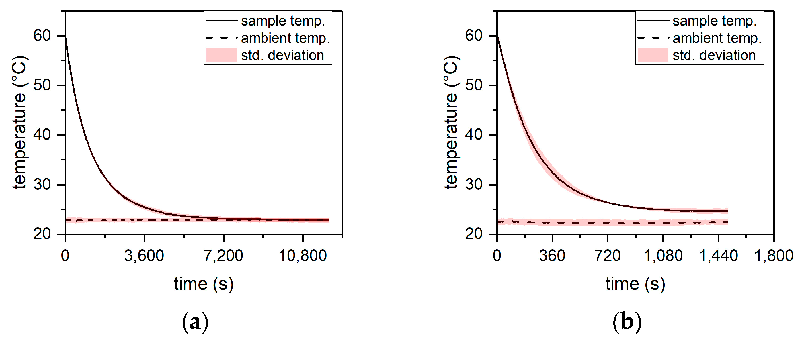

Figure 3.
Small cylinder dimensionless temperature versus time.
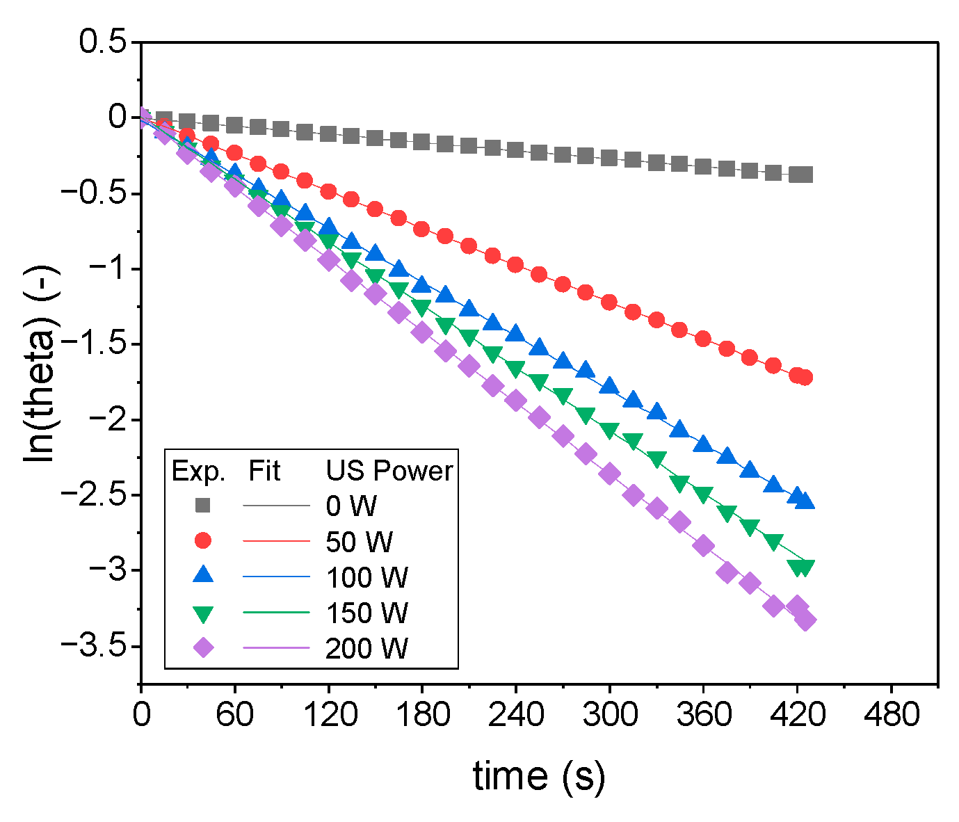
Figure 4.
Approximation of the heat transfer coefficient: (a) cube; (b) cuboid; (c) cylinder; (d) small cylinder.
Figure 4.
Approximation of the heat transfer coefficient: (a) cube; (b) cuboid; (c) cylinder; (d) small cylinder.
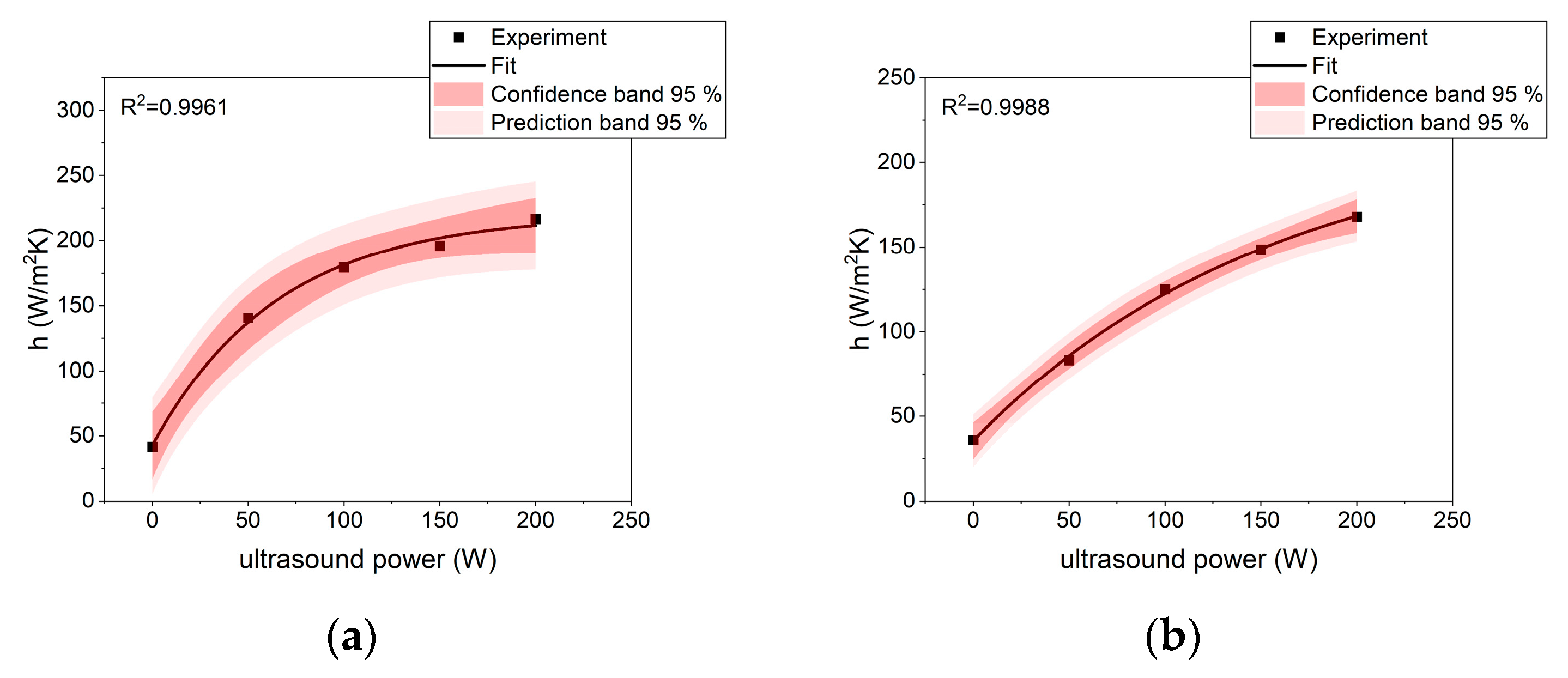

Figure 5.
Heat transfer enhancement coefficient for particular samples cooled under different conditions.
Figure 5.
Heat transfer enhancement coefficient for particular samples cooled under different conditions.


Table 1.
Dimensions of the particular sample.
| Sample | Dimensions | ||
|---|---|---|---|
| Length (mm) | Width (mm) | Height (mm) | |
| Cube | 30 | 30 | 30 |
| Cuboid | 120 | 30 | 40 |
| Diameter (mm) | Height (mm) | ||
| Cylinder | 30 | 30 | |
| Small cylinder | 20 | 20 | |
Table 2.
Values of the heat transfer coefficient h (W/m2K) for particular shapes and processes.
| Sample | US Power | ||||
|---|---|---|---|---|---|
| 0 [W] | 50 [W] | 100 [W] | 150 [W] | 200 [W] | |
| cube | 41.64 ± 0.76 | 140.60 ± 3.02 | 179.50 ± 4.53 | 1926.20 ± 6.04 | 216.50 ± 6.04 |
| cuboid | 36.09 ± 0.31 | 83.28 ± 1.17 | 124.90 ± 4.53 | 148.50 ± 1.13 | 167.90 ± 1.13 |
| cylinder | 45.27 ± 0.76 | 150.80 ± 1.22 | 188.80 ± 1.51 | 230.10 ± 10.6 | 239.70 ± 6.80 |
| small cylinder | 52.43 ± 0.50 | 238.70 ± 4.53 | 396.50 ± 6.55 | 418.20 ± 3.24 | 487.90 ± 10.60 |
Table 3.
Values of the a, b, and c constants.
| Sample | a | b | c |
|---|---|---|---|
| cube | 219.9 ± 8.1 | 177.4 ± 9.3 | 9.85 × 10⁻¹ ± 2.10 × 10⁻³ |
| cuboid | 219.8 ± 14.6 | 184.4 ± 13.8 | 9.94 × 10⁻¹ ± 8.84 × 10⁻⁴ |
| cylinder | 256.5 ± 14.0 | 210.0 ± 14.6 | 9.87 × 10⁻¹ ± 2.25 × 10⁻³ |
| small cylinder | 519.3 ± 38.6 | 466.3 ± 39.1 | 9.88 × 10⁻¹ ± 2.50 × 10⁻³ |
Disclaimer/Publisher’s Note: The statements, opinions and data contained in all publications are solely those of the individual author(s) and contributor(s) and not of MDPI and/or the editor(s). MDPI and/or the editor(s) disclaim responsibility for any injury to people or property resulting from any ideas, methods, instructions or products referred to in the content. |
© 2023 by the authors. Licensee MDPI, Basel, Switzerland. This article is an open access article distributed under the terms and conditions of the Creative Commons Attribution (CC BY) license (https://creativecommons.org/licenses/by/4.0/).
Share and Cite
MDPI and ACS Style
Musielak, G.; Mierzwa, D.; Łechtańska, J. Experimental Investigation of Enhancement of Natural Convective Heat Transfer in Air Using Ultrasound. Appl. Sci. 2023, 13, 2516. https://doi.org/10.3390/app13042516
AMA Style
Musielak G, Mierzwa D, Łechtańska J. Experimental Investigation of Enhancement of Natural Convective Heat Transfer in Air Using Ultrasound. Applied Sciences. 2023; 13(4):2516. https://doi.org/10.3390/app13042516
Chicago/Turabian StyleMusielak, Grzegorz, Dominik Mierzwa, and Joanna Łechtańska. 2023. "Experimental Investigation of Enhancement of Natural Convective Heat Transfer in Air Using Ultrasound" Applied Sciences 13, no. 4: 2516. https://doi.org/10.3390/app13042516
Note that from the first issue of 2016, this journal uses article numbers instead of page numbers. See further details here.