Article

Research on the Stability and Water Isolation of Waterproof Coal Pillars between Adjacent Working Faces under the Influence of Water Ponding Goaf—A Case Study

State Key Laboratory of Coal Resources and Safe Mining, China University of Mining and Technology, Xuzhou 221116, China
*
Author to whom correspondence should be addressed.
Appl. Sci. 2024, 14(2), 884; https://doi.org/10.3390/app14020884
Submission received: 21 December 2023 / Revised: 17 January 2024 / Accepted: 17 January 2024 / Published: 19 January 2024
(This article belongs to the Section Civil Engineering)

Abstract

:
Retaining a waterproof coal pillar is an important measure to defend against water inrush accidents in mining areas and guarantee the safe mining of the next working face. In this paper, the mechanical model of the coal pillar is established and the calculation formula of the waterproof coal pillar width is derived. Then, the development of the water-conducting fracture zone of the overlying rock layer under different coal pillar widths is analyzed using numerical simulation and finally, the integrity of the coal pillar is detected using the geophysical survey method. The main conclusions are as follows: (1) According to the mechanical failure characteristics of the coal pillar, it can be divided into the plastic zone, elastic zone, and water pressure damage zone. The mechanical calculation model for each zone was established, and the formula for calculating the width of the waterproof coal pillar was obtained. (2) Numerical simulation was employed to investigate the development condition of the water conducting fracture zone in the overlying rock strata under the actual width of the waterproof coal pillar; the simulation results indicated that the water conducting fracture zone of two working faces was not connected, which can effectively prevent the accumulation of water in the 2303 goaf. (3) On-site geophysical surveys determined that the influence of water-logged goaf on the coal pillar is between 5 to 15 m; the integrity of the waterproof coal pillar is good, which effectively prevents water accumulation in the previous working face goaf and ensures safe mining in the next working face.

1. Introduction

Coal is an essential material for human survival as it plays a crucial role in driving the global economy and social development [1,2,3,4]. Additionally, it serves as a foundation for countries worldwide to formulate their diplomatic strategies. In China, the energy distribution pattern indicates that coal will continue to be the primary source of energy consumption in the foreseeable future [5,6,7,8,9]. Mine water surges caused by coal extraction are a significant challenge that affects the safe operation of mines [10,11]. In recent years, as coal mining depth, intensity, speed, and scale have increased, the issue of mine water emergence has become increasingly serious. This not only leads to significant casualties and economic losses, but also gradually damages the ecological environment surrounding the mining area over time [12,13,14]. Currently, one of the primary methods for preventing and controlling water-surge disasters in mines is by retaining waterproof coal pillars. These coal pillars prevent water from entering the next working face from the goaf and ensure the safety of the mining roadway in the next working face.
The earliest and most widely used calculation formula in Europe is the British waterproof coal pillar calculation formula, which has certain limitations and is only applicable to the calculation of harder coal seams. In addition, the calculation formula only considers the influence of coal seam thickness and water pressure on the size of coal pillars and ignores the influence of buried depth and coal strength on the size of coal pillars [15,16,17]. In the United States, the earliest known waterproof coal pillar calculation formula was proposed by Dunn in 1846 [18,19,20], which was calculated after a given depth, and thus, the calculated size of coal pillars is on the smaller side. Indian scholars have adopted the waterproof coal pillar calculation method of coal pillar strength and anti-slip force, taking into account the two conditions of stabilized mining areas and goaf, but the limitations of its applicability and the overly complex parameters of the formula make its application inconvenient. Many countries’ mining safety regulations on the minimum width of the waterproof coal pillar have made specific provisions. For example, Poland’s safe mining regulations require that the coal (rock) height in the aquifer under the coal seam outcrops be eight times the thickness of the mined coal seam, whereas India’s regulations require a distance of 60 m in all directions of waterlogged areas and mining areas [21,22,23,24]. Many academics in China have proposed corresponding methods for determining the size of waterproof coal pillars for certain geological conditions. Deng Xiangyue [25] discussed the types and calculation methods of waterproof coal pillars and proposed that the waterproof coal pillar needs to consider the hydrogeological conditions, the depth of the coal seam, the mechanical properties of the surrounding rock, and other factors; in addition, they need to be adapted to the coal seam mining method, the form of the support, and the strength of the coal seam. Liu Yang et al. [26,27] divided the waterproof coal pillars into permeable area and waterproof area and found that regardless of the fault waterproof coal pillars or waterproof coal pillars between adjacent working faces, the real waterproof effect is the undamaged elasticity area inside the coal pillar. Liu Changwu and Ding Kaixu [28] simplified the width of coal pillars by treating it as a plane strain problem and deduced the formula for calculating the critical size of the elastic zone in the coal pillar under the action of mine pressure and water pressure. Yao Zhongling [29] determined the range of waterproof coal pillar retention in shallow buried working faces by comparing the thickness of the overlying rock layer on the working face with the width of the waterproof coal pillar in the coal seam outcrop. Xie Huadong [30] studied the safety coal pillar in the outcrop area of a working face in Dongtan Coal Mine using the back calculation method, which was based on the drilling exploration data and the height of the water-conducting fissure zone. Wan Zhen and Xing Wenbin [31] determined the waterproof coal pillar line of the mine based on the bedrock elevation detected by drilling holes near the outcrop area of the coal seam, and the height of the water-conducting fracture zone corresponding to the mining of coal seams at each exploration line. Du Shaoneng [32] analyzed the performance of water-bearing and water-isolating layers in thick loose strata and proposed the relationship between waterproof coal pillars and the height of the water-conducting fracture zone. Wang Rui and An Xiucheng [33,34,35] proposed the concept of the “water permeability coefficient of protective layer” to solve the problem of setting waterproof coal pillars under a thick loose layer.
Currently, the width of waterproof coal pillars is still mainly determined based on empirical knowledge rather than a systematic method. There is a lack of methods and theories for reserving waterproof coal pillars between adjacent working faces. The width of the waterproof coal pillar must strike a balance to avoid the unnecessary waste of coal resources while ensuring the safe production of the coal mine. Hence, it becomes essential to investigate the optimal width for retaining waterproof coal pillars between working faces in water-logged goaf.
Cuijiagou 2303 working faces had roof water inflow during the mining process and its goaf was waterlogged. Therefore, in order to ensure the safe mining of the next working face, there is a need to retain a certain width of waterproof coal pillar between the two working faces. This study examines the waterproofing of the coal pillar between the 2303 and 2305 working faces of the Cuijiagou coal mine. This research employs theoretical analysis, numerical simulation, and geophysical survey methods to evaluate the safety of the waterproof coal pillars. First, theoretical analysis and calculations are conducted to determine the theoretical width of the waterproof coal pillar. This width is then compared to the actual width. Subsequently, this study analyzes the development of water-conducting fracture zones under coal pillars of different widths. Finally, these findings are combined with the results of geophysical surveys of the working faces to ensure that the waterproof coal pillars can ensure the safe mining of the working faces.

2. Geological Condition

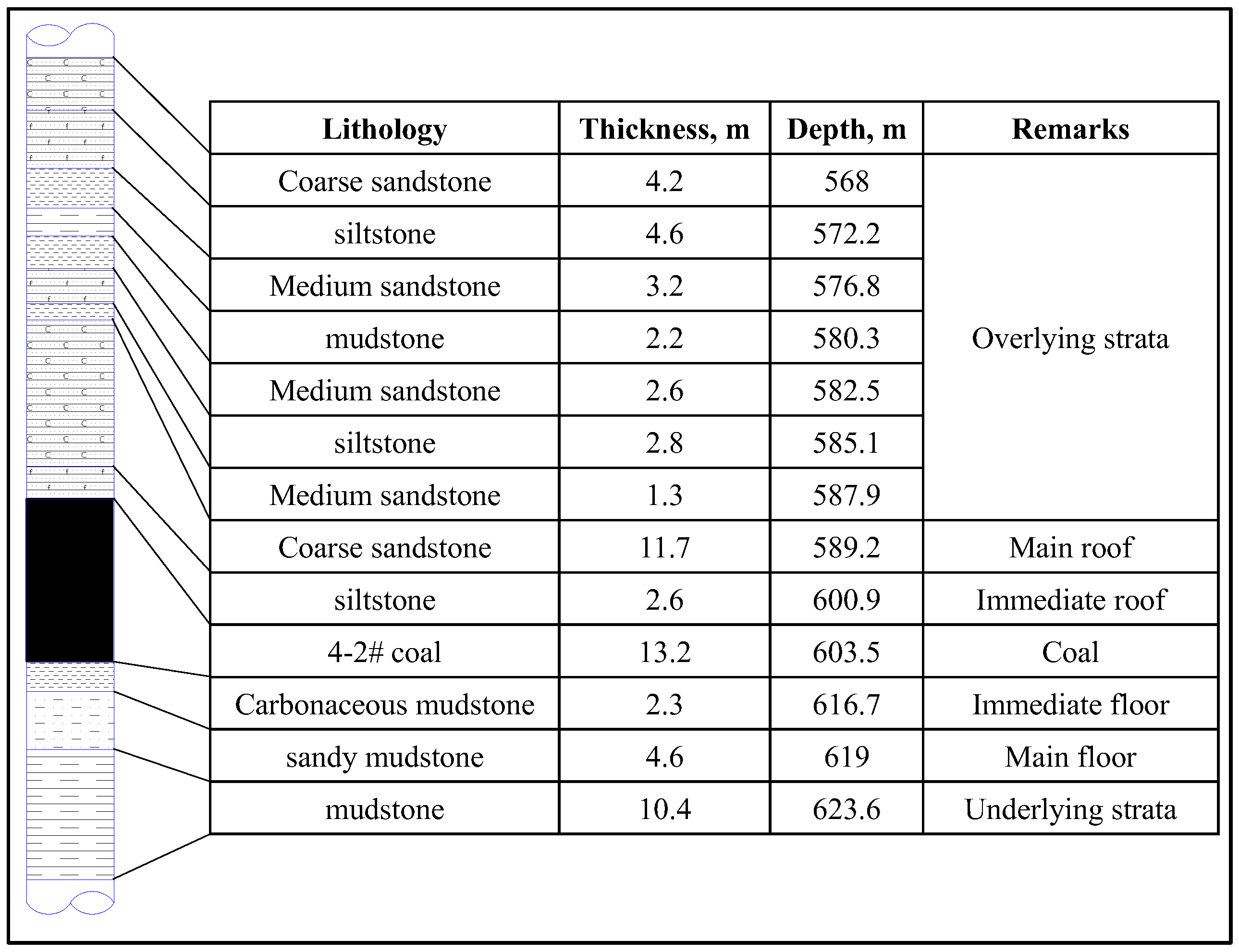
2.1. Geological Conditions of the Working Face

Shaanxi Province Cuijiagou Coal Mine is located in the south-central part of the Jiao Ping Mining Area of Huanglong Jurassic Coal Field, with a length of about 7.7 km from east to west, a width of about 5.6 km from north to south, and a well field area of 28.2008 km2. The main coal seam of the mine is 4-2# coal, and the mine’s production capacity is 1.95 Mt/a. The 2305 comprehensive caving coal face is the continuous face of the mine’s three-disk area, and it is also the fourth face mined in the three-disk area of the mine. It is located in the middle of the mining area, spread along the north-south direction, with a tendency advancing length of 1460 m, a working face length of 200 m, a thickness of the working face mining of 3.5 m, and a caving coal height of 8.5 m. The depth of the 4-2# coal seam in the third disk area is 400~700 m, and the inclination angle is about 5°. The locations of the Cuijiagou coal mine and the 2305 working face are shown in Figure 1.
According to the geological data of the coal mine, the geological conditions of the working face are simple, with no obvious tectonics or fault zones. The strata of the mine field from old to new and from top to bottom, are as follows: Triassic Upper Yongping Formation (T3y), Lower Jurassic Fuxian Formation (J1f), Middle Jurassic Yan’an Formation (J2y), Zhiluo Formation (J2z), Lower Cretaceous Yijun Formation (K1y), Luohe Formation (K1l), Huachi Formation (K1h), and Quaternary (Q) strata. The main roof of the coal seam is gray-white fine powder sandstone, the immediate roof is mainly powder sandstone, and there are medium-grained sandstone and coarse-grained sandstone in the local section. The floor of the coal seam is gray and gray-black mudstone, interspersed with fine sandstone. A comprehensive histogram of coal and rock of the 2305 working face is shown in Figure 2.

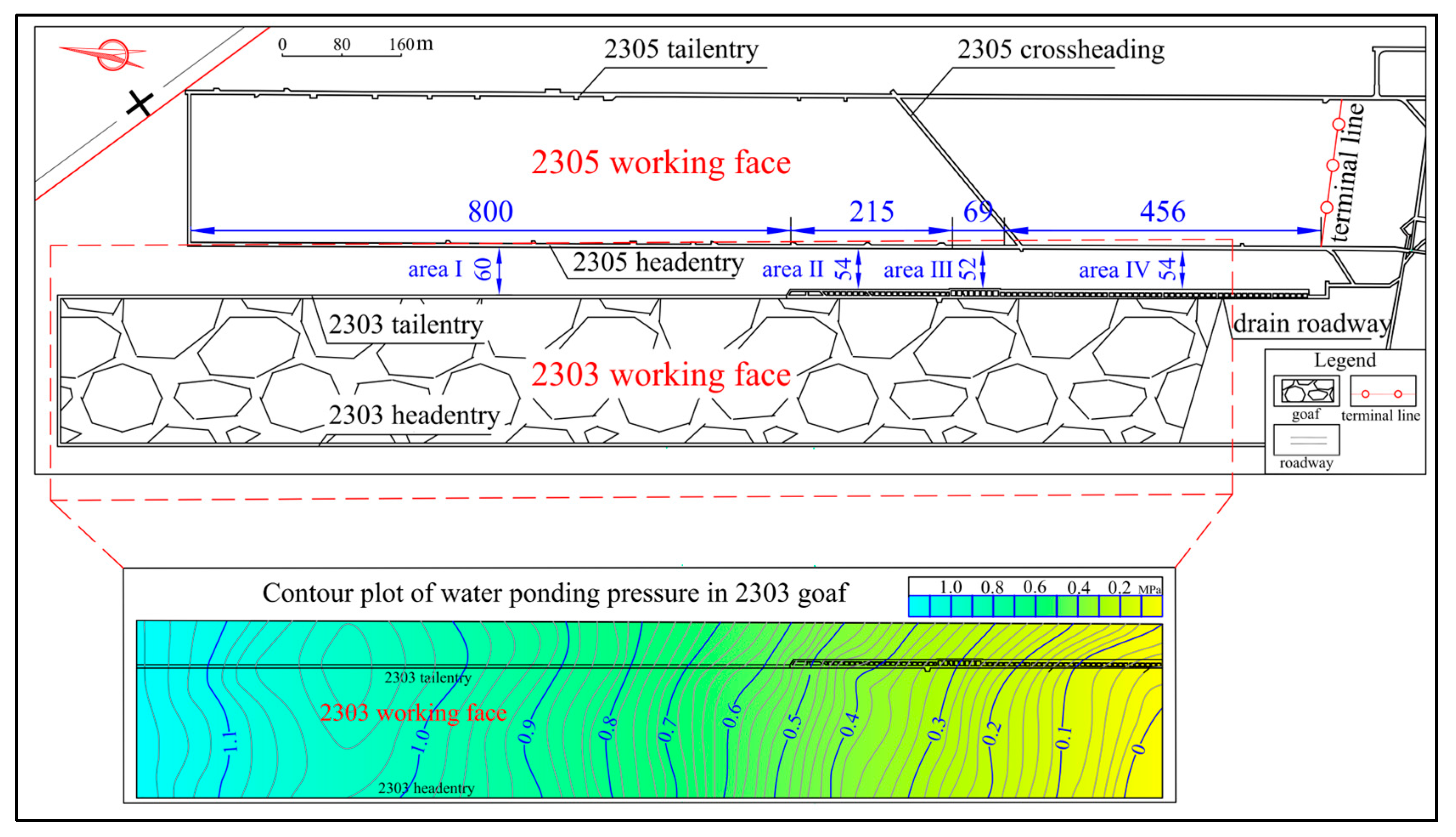
2.2. Water Accumulation Condition in Working Faces

The 2303 working face goaf had water accumulation, which was predicted to be 873,000 m3. Currently, the water outflow of the 2303 working face tailentry water retaining wall is 160~200 m3/h. In order to facilitate the drainage, a drain roadway was constructed on the outside of the 2303 tailentry, causing the uneven width of the coal pillar between the working face, with the width of the coal pillar ranging from 52 to 60 m. The 2305 working face water pressure distribution is shown in Figure 3.
The statistics of water accumulation pressure in different areas of the 2305 working face are shown in Table 1.

3. Analysis of the Coal Pillar Width under the Influence of the Water-Logged Goaf

3.1. Theoretical Calculation of the Width of Waterproof Coal Pillars

When there is a waterlogged goaf in the face to be mined and its adjacent faces, the side of the coal pillar in the section is affected by the water pressure. For the safety of the next working face, a certain width of the coal pillar is required. According to the damage characteristics of the section coal pillar from the previous working face to the next working face, it is divided into water a pressure damage zone (water seepage area), an elastic zone (water isolation area), and a plastic zone. The structure of the waterproof coal pillar is divided and the distribution of force is shown in Figure 4.
The waterproof coal pillar width can be calculated as follows:
l = l 1 + l 2 + l 3
where l is the waterproof coal pillar retention size (in m), l1 is the width of the plastic zone (in m), l2 is the width of the elastic area (in m), and l3 is the water pressure damage area width (in m).

3.2. Calculation of the Width of the Plastic Zone of Waterproof Coal Pillars

Since the coal pillar is long and its length significantly exceeds its height, a specific cross-section was taken along the width direction at a certain position along the length of the coal pillar. A microelement body within the cross-section was then considered, treating the problem as plane stress. The width of the plastic zone was calculated based on Cullen’s criterion. The calculation of coal pillar width using Cullen’s criterion was based on the following assumptions:
(1)
The properties of the coal body are continuous, homogeneous, isotropic, and perfectly elastic.
(2)
Plastic damage occurs when the coal pillar is subjected to shear stress, and the damaged surface is parallel to the coal seam level.
(3)
The coal body undergoes plastic deformation, and the deformation is negligible.
(4)
The force on the coal pillar only considers the gravity of the overlying rock and does not consider the influence of its tectonic stress.
(5)
The stresses above the coal body are symmetrical about the neutral plane.
(6)
The influence of coal body force is not considered.
The width of the plastic zone of the coal column in the section was calculated according to the assumptions above. The mechanical calculation model of the plastic zone width is shown in Figure 5.
The equilibrium equations are listed with the x-axis and y-axis as projection axes, and the plane stress equilibrium differential equations can be obtained as follows:
σ x x + τ y x y = 0 σ y y + σ x y x = 0
When critical damage occurs to the coal pillar along the seam level, the stresses between the seams satisfy the stress limit equilibrium condition, i.e., Cullen’s criterion [36]:
τ y x = ( C 0 + σ y tan φ 0 )
where C0 is the cohesive force between the coal body and roof and floor (in MPa) and φ0 is the friction angle between the coal seam and the roof and floor (in °).
The stress boundary condition at the interface between the plastic and elastic regions is as follows:
( σ y ) x = l 1 = K 1 γ H ( σ x ) x = l 1 = λ K 1 γ H
where λ is the lateral pressure coefficient at the interface between plastic and elastic zones.
Equations (3) and (4) can be obtained as follows:
σ y x tan φ 0 = σ y y
Assume that the function σy is:
σ y = f ( x ) g ( y ) + a
The combination of Equations (5) and (6) yields:
f ( x ) f ( x ) tan φ 0 = g ( y ) g ( y )
This can be obtained by making the left and right sides of the equal sign of Equation (7) equal to the constant b:
f ( x ) = c 1 e b tan φ 0 x g ( y ) = c 2 e b y
Equations (3), (6), and (8) are obtained by association:
σ y = c e b x tan φ 0 τ y x = c e b x tan φ 0 e b x + a tan φ 0 + C 0
where a, b, c, c1, c2 are constants to be determined and c = c 1 c 2 .
By separating the plastic zone l1 section of the coal column, with the horizontal direction of the combined force being zero, the following formula is obtained:
h λ ( σ x ) x = l 1 + 2 0 l 1 τ y x d x p x h = 0
Equations (4) and (10) can be obtained by joining them:
h λ d ( σ y ) x = l 1 d l 1 2 tan φ 0 ( σ y ) x = l 1 2 C 0 = 0
The solution can be obtained as follows:
( σ y ) x = l 1 = b 1 e tan φ 0 h λ C 0 tan φ 0
Equations (9) and (12) are obtained by associating them:
a = C 0 tan φ 0 b = 2 tan 2 φ 0 h λ b 1 = c e h b 2 = c e tan 2 φ 0 λ
Equations (4) and (9)–(13) are obtained by association:
b 1 e 2 tan φ 0 h λ l 1 C 0 tan φ 0 = K 1 γ H K 1 γ H P x λ + b 1 ( 1 e 2 tan φ 0 h λ l 1 ) = 0
Equations (13) and (14) are obtained by associating them:
b 1 = C 0 tan φ 0 + P x λ c = ( C 0 tan φ 0 + P x λ ) e tan 2 φ 0 λ
The combination of Equations (9), (13), and (15) can be used to calculate the stress above the coal seam at a distance l1 from the plastic zone as follows:
σ y = ( C 0 tan φ 0 + P x λ ) e tan φ 0 h λ ( 2 x + 2 y tan φ 0 h tan φ 0 ) C 0 tan φ 0
τ y x = ( C 0 + P x λ tan φ 0 ) e tan φ 0 h λ ( 2 x + 2 y tan φ 0 h tan φ 0 )
By substituting the stress boundary condition at the interface between the plastic zone and the elastic zone into Equation (16), the width of the plastic zone of the zone waterproof coal column can be calculated as:
l 1 = h λ 2 tan φ 0 ln K 1 γ H + C 0 tan φ 0 C 0 tan φ 0 + P x λ + ( h 2 y ) tan φ 0
During actual mining operations, different mining methods, the speed of working face mining, and other factors can affect the plastic zone of the coal pillar, resulting in an expansion of the range of the plastic zone. Therefore, the mining disturbance factor was also considered. Furthermore, the lateral constraints of the coal pillar gangs are uncertain due to the mining of the working faces. In order to ensure that the width of the coal pillar calculated in Equation (18) meets the safety requirements for the working faces, Px must be 0. By substituting this value into the above formula, the following expression can be used to calculate the width of the plastic zone:
l 1 = h d 2 tan φ 0 ln ( 1 + K 1 γ H C 0 tan φ 0 ) λ + tan 2 φ 0
where h is the height of coal pillar (in m), d is the mining influence factor, d = 1.5~3.0, φ0 is the friction angle at the interface between the coal seam and the roof and the floor plate (in °), K1 is the stress concentration factor of coal body in the plastic zone, γ is the rock volume force (in kN/m3), H is the depth of the coal seam (in m), and C0 is the cohesive force at the interface between coal seam and top and bottom plate (in MPa).
Through the collection of information and on-site research, the relevant parameters of the Cuijiagou 4-2# working face were obtained as follows: h = 12 m, H = 600 m, K1 = 2.5, rock volume force γ = 25 kN/m3, mining influence factor d = 1.5, C0 = 3.5 MPa, and φ0 = 30°.
The lateral pressure coefficient was calculated as:
λ = σ x σ y = 1 sin φ 1 + sin φ
where φ is the angle of friction within the coal (in °).
Solving Equation (20) yields λ = 0.3.
By substituting the above parameters into Equation (19), the following was obtained:
l 1 = 12 × 1.5 2 × tan 30 ln ( 1 + 2.5 × 2.5 × 6 3.5 × tan 30 ) 0.3 + tan 2 30 = 14.26   m

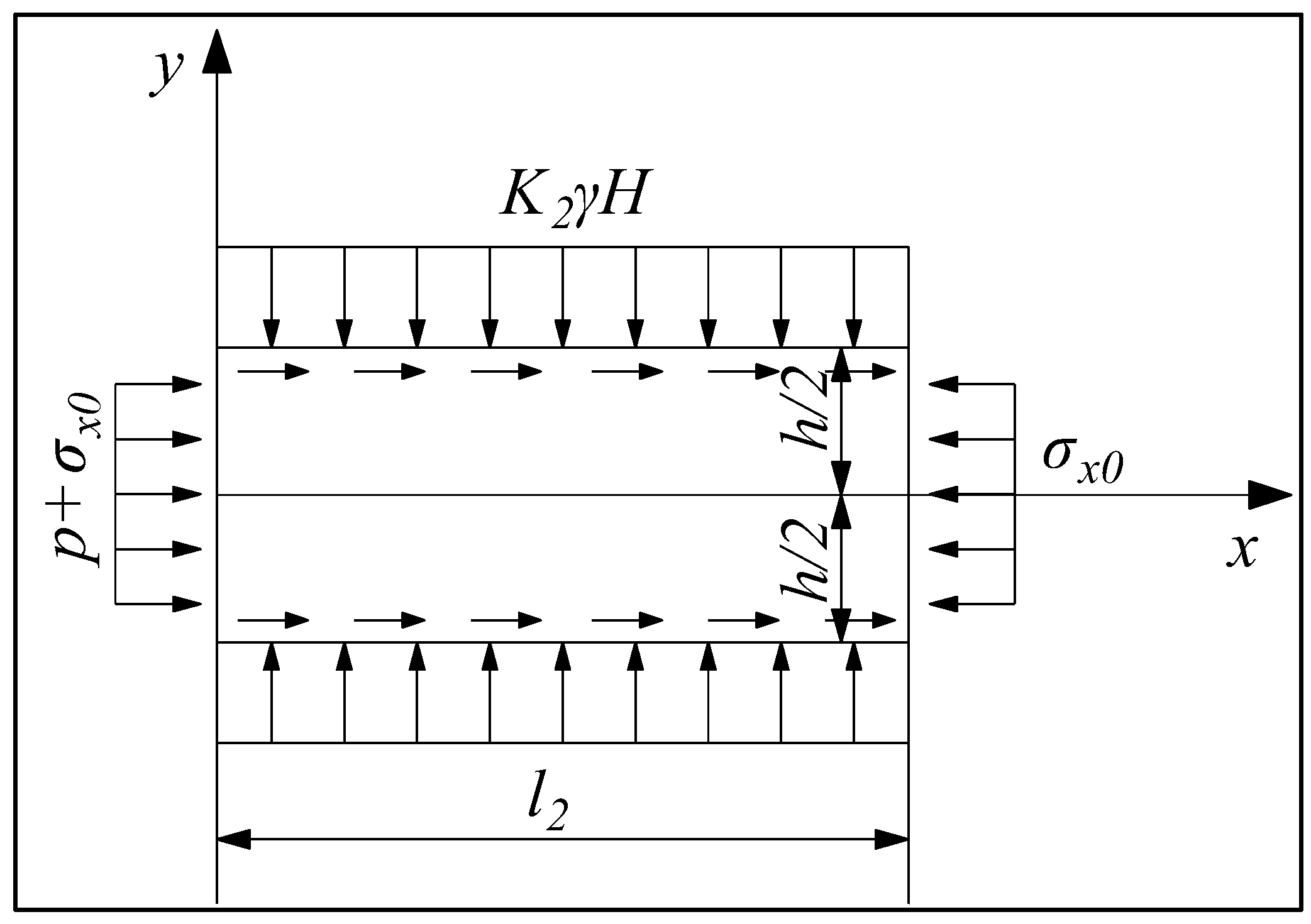
3.3. Calculation of the Width of the Elastic Zone of the Waterproof Coal Pillar

The coal seam in the elastic zone is influenced by lateral water pressure and mining stress at the mining face in waterlogged mining areas. Therefore, a mechanical model was developed to convert the problem into a plane stress scenario to determine the width of the coal pillar. Meanwhile, the mechanical model makes the following assumptions. The mechanical calculation model of coal pillar width in the elastic core area is shown in Figure 6.
(1)
The coal pillar is a uniform, continuous, and isotropic elastomer.
(2)
The stress σx0 on both sides of the coal body in the elastic area is symmetric and uniformly distributed.
(3)
The stress K2γH above the coal body in the elastic area is uniformly distributed and symmetric about the x-axis.
(4)
The lateral water pressure p suffered by the coal body in the elastic area is uniformly distributed, ignoring the blocking effect of the plastic zone on the water pressure, and the size of the water pressure is calculated in accordance with the maximum value measured in the field.
The elastic area coal pillar model boundary conditions are:
( σ y ) y = h 2 = K 2 γ H ( σ x ) x = 0 = p σ x 0 ( σ x ) x = l 2 = σ x 0
The semi-inverse solution method was used to solve the model stress components, assuming that each stress component satisfies the stress function Φ = Φ(x, y); therefore, the stress function was solved.
It was assumed that σy does not vary with x, and σy is a function of y. Therefore, the expression of the assumed function is as follows:
σ y = f ( y )
In the direction of the coal pillar width, the mine pressure K2γH above the coal pillar is uniformly distributed, so the following formula can be obtained:
f ( y ) = K 2 γ H
Based on the relationship between the Airy stress function and the stress components:
σ x = 2 Φ y 2 σ y = 2 Φ x 2 τ y x = 2 Φ x y
The stress function representation of the compatibility equation is:
4 Φ x 4 + 2 4 Φ x 2 y 2 + 4 Φ y 4 = 0
Substituting σy into Equation (24) yields:
2 Φ x 2 = f ( y ) = K 2 γ H
Integrating over x yields:
Φ x = x f ( y ) + f 1 ( y ) Φ = x 2 2 f ( y ) + x f 1 ( y ) + f 2 ( y )
where f1(y) and f2(y) are both y functions to be determined.
Substituting Equation (27) into the compatibility Equation (25) yields:
1 2 d 4 f ( y ) d y 4 x 2 + d 4 f 1 ( y ) d y 4 x + d 4 f 2 ( y ) d y 4 + 2 d 2 f ( y ) d y 2 = 0
Since the stress function must satisfy the compatibility equation in the region, the coefficients and the free term of Equation (28) must be equal to zero, and the solution of the equation is polynomial:
f 1 ( y ) = A y 3 + B y 2 + C y + D
f 2 ( y ) = E y 3 + F y 2 + G y + I
Substituting Equations (23), (29), and (30) into Equation (27) yields:
Φ ( x , y ) = K 2 γ H 2 x 2 + ( A y 3 + B y 2 + C y + D ) x + ( E y 3 + F y 2 + G y + I )
Substituting Equation (31) into Equation (24) yields the stress component as follows:
σ x = 2 Φ y 2 = x ( 6 A y + 2 B ) + ( 6 E y + 2 F ) σ y = 2 Φ x 2 = f ( y ) = K 2 γ H τ x y = 2 Φ x y = ( 3 A y 2 + 2 B y + C )
Substituting Equation (21) into Equation (32) yields:
σ x = p l 2 x ( p + σ x 0 ) σ y = f ( y ) = K 2 γ H τ x y = p l 2 y
The two principal stresses σ1 and σ3 at any point in the elastic zone can be obtained from each stress component σx, σy, and τyx in elastic mechanics:
σ 1 σ 3 = σ x + σ y 2 ± ( σ x σ y 2 ) + τ 2 x y )
For the coal rock body damage problem, the principal stress relationship satisfies the following equation:
σ 1 = 1 + sin φ 1 sin φ σ 3 + 2 c cos φ 1 sin φ
The width of the coal pillar in the elastic core area can be obtained by associating Equations (33)–(35):
l 2 = p h [ 2 c cos φ sin φ ( p + σ x 0 + K 2 γ H ) ] 2 ( K 2 γ H p σ x 0 ) 2
where p is the head pressure (in MPa), h is the height of the coal pillar (in m), c is the coal cohesion (in MPa), φ is the coal body internal friction angle (in °), K2 is the stress concentration coefficient within the coal body in the elastic zone, and σx0 is the horizontal stress at the junction of hydraulic damage area and elastic core area (in MPa).
The relationship equation between vertical stress and lateral stress is:
σ x 0 = 1 sin φ 1 + sin φ K 3 γ H 2 c cos φ 1 + sin φ
where K3 is the stress concentration factor of the coal body in the water pressure damage area.
Based on the information collected, the maximum head pressure p = 1.06 MPa, h = 12 m, c = 3.0 MPa, φ = 30 °, K2 = 1.5, and K3 = 4,
Substituting the above parameters and Equation (37) into Equation (36) yields:
l 2 = 12 × 1.06 [ 2 × 3 cos 30 sin 30 ( 1.06 + 13.08 + 1.5 × 2.5 × 6 ) ] 2 ( 1.5 × 2.5 × 6 1.06 13.08 ) 2 = 4.89   m

3.4. Calculation of the Width of the Water Pressure Damage Zone of Waterproof Coal Pillars

The calculation model for the plastic zone and water pressure damage zone is influenced by mining pressure. However, the coal seam situated near the water accumulation area of the mining site is impacted by water pressure and erosion, leading to its loosening and eventual collapse. Therefore, the impact of water on the coal body was considered when determining the width of the coal pillar in the water pressure damage zone. The mechanical calculation model of the width of the coal pillar in the water pressure damage zone is shown in Figure 7.
The weakening factor of water on the coal body is calculated as:
η 0 = σ w σ c
where σw is the compressive strength of waterlogged coal samples (in MPa) and σc is the compressive strength of dried coal samples (in MPa).
According to Fang Gang’s [37] solution for the width of the hydraulic damage zone, Equation (38) can be obtained by substituting Equation (19):
l 3 = h d ( 1 + η 0 ) 2 tan φ 0 ln ( 1 + K 3 γ H C 0 tan φ 0 ) λ + tan 2 φ 0
Substituting the relevant parameters into Equation (39) yields:
l 3 = 12 × 1.5 × ( 1 + 0.52 ) 2 tan 30 ln ( 1 + 4 × 2.5 × 6 3.5 tan 30 ) 0.3 + tan 2 30 = 24.68   m

3.5. Determination of Width of Waterproof Coal Pillar

By using the above calculation of the width of the coal pillar in the plastic zone, elastic zone, and water pressure damage zone, the theoretical width of the waterproof isolated coal pillar is determined as follows:
l = l 1 + l 2 + l 3 = h d 2 tan φ 0 ln ( 1 + K 1 γ H C 0 tan φ 0 ) λ + tan 2 φ 0 + p h [ 2 c cos φ sin φ ( p + σ x 0 + K 2 γ H ) ] 2 ( K 2 γ H p σ x 0 ) 2 + h d ( 1 + η 0 ) 2 tan φ 0 ln ( 1 + K 3 γ H C 0 tan φ 0 ) λ + tan 2 φ 0 = 14.26   m + 4.89   m + 24.68   m = 43.83   m
Therefore, the minimum theoretical width of the waterproof coal pillar between two working faces in Cuijiagou is 44 m.

4. Safety Analysis of Waterproof Coal Pillar Width in the Working Faces

According to Article 92 in the Rules for Prevention and Control of Water in Coal Mines, waterproof coal pillars should be retained when there is a large amount of water in the old goaf. Since the working face is not affected by the bottom plate water, when considering the sudden water in the horizontal direction, the formula for retaining waterproof coal pillars in the Rules for Prevention and Control of Water in Coal Mines can be utilized to account for the width of coal pillars.
L = 0.5 K M 3 p K p 20   m
where L is the retaining width of the waterproof coal pillar (in m), K is the safety coefficient, generally 2~5, M is the thickness of the coal seam or mining height (in m), p is the ponding pressure (in MPa), and Kp is the coal tensile strength (in MPa).
Kp takes the value of 0.94 MPa, and K takes the value of 4. Other parameters can be substituted into Formula (40) for calculation. The calculation results of coal column width are shown in Table 2.
The theoretical calculation value of the waterproof coal pillar width of the section in the previous section was determined to be 44 m, whereas by combining the calculation result of coal pillar width with the empirical formula found in the rules of coal mine water prevention and control, the calculated value of coal pillar width under both calculation methods is smaller than the actual value of the coal pillar width.

4.1. Analysis of the Development of the Water Conducting Fracture Zone in the Working Face

After the analysis of the width of water-adjacent coal pillars in the waterlogged goaf, in order to further determine its applicability, the height of the development of water-conducting fracture zone in the overlying rock strata of the 2303 and 2305 workings was studied to determine the development of the fracture zone above the coal pillar.

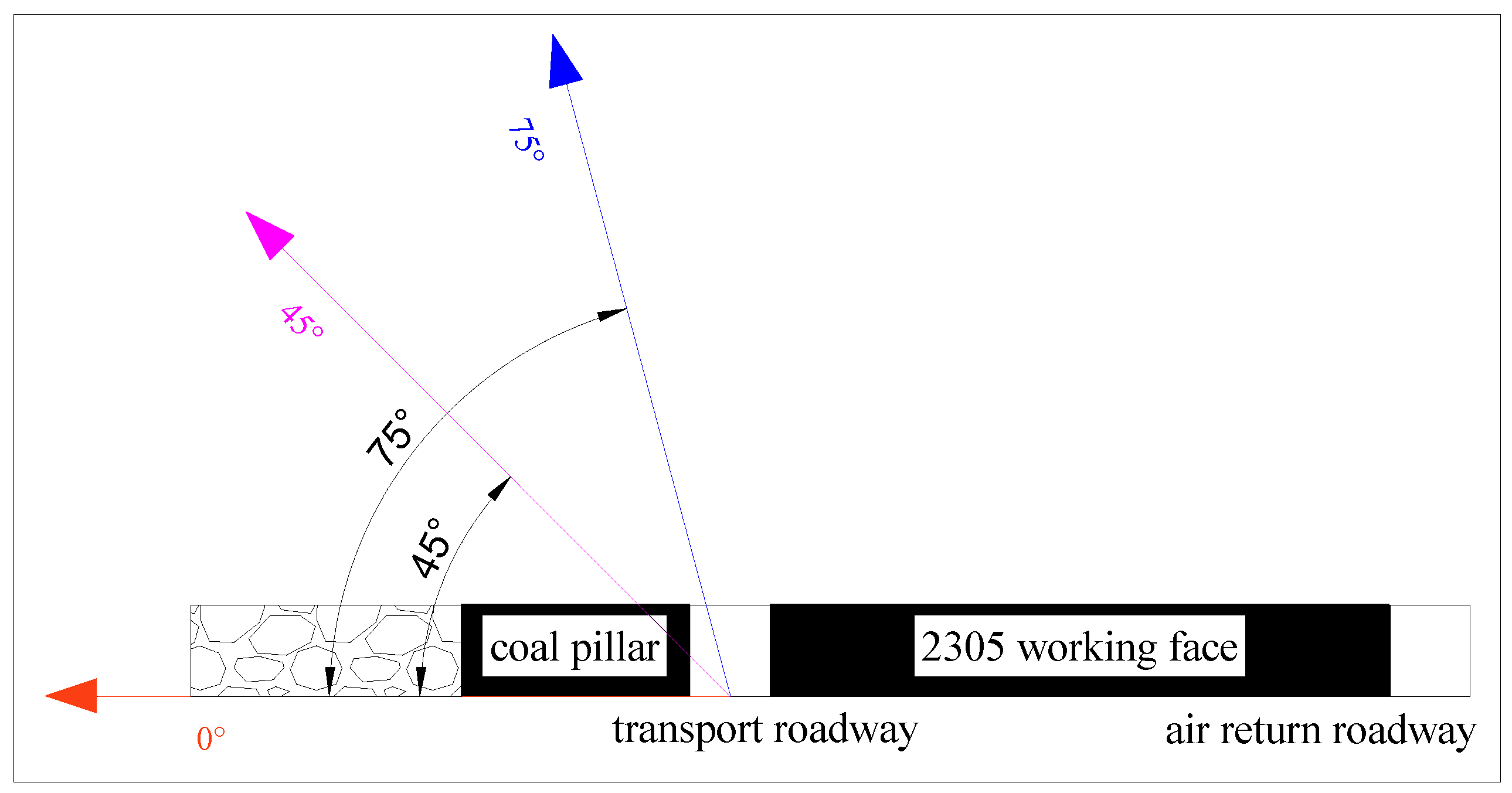
4.2. Calculation of the Development Height of the Water Conducting Fracture Zone

The empirical formula for calculating the height of the water-conducting fracture zone is provided in the Guidelines for Retaining Coal Pillar in Buildings, Water Bodies, Railroads and Major Shafts and Mining of Compacted Coal. The height of the water-conducting fracture zone was calculated by using the corresponding formula:
H l i = 100   M 0.23   M + 6.10 ± 10.42
where Hli is the height of the water-conducting fracture zone (in m) and M is the cumulative mining thickness of the coal seam (in m).
The Cuijiagou 2305 working face overburden rock lithology for the medium-hard, near horizontal coal seam, with an average thickness of the coal seam of 12 m, can be substituted into the Formula (41) to obtain the 2305 working face water-conducting fracture zone height of 125.02~145.86 m. The 2303 working face average mining thickness of 7 m can be substituted into the Formula (41) to obtain the 2303 working face water-conducting fracture zone height of 80.37~101.21 m.

4.3. Numerical Simulation of the Developmental Height of the Water-Conducting Fracture Zone

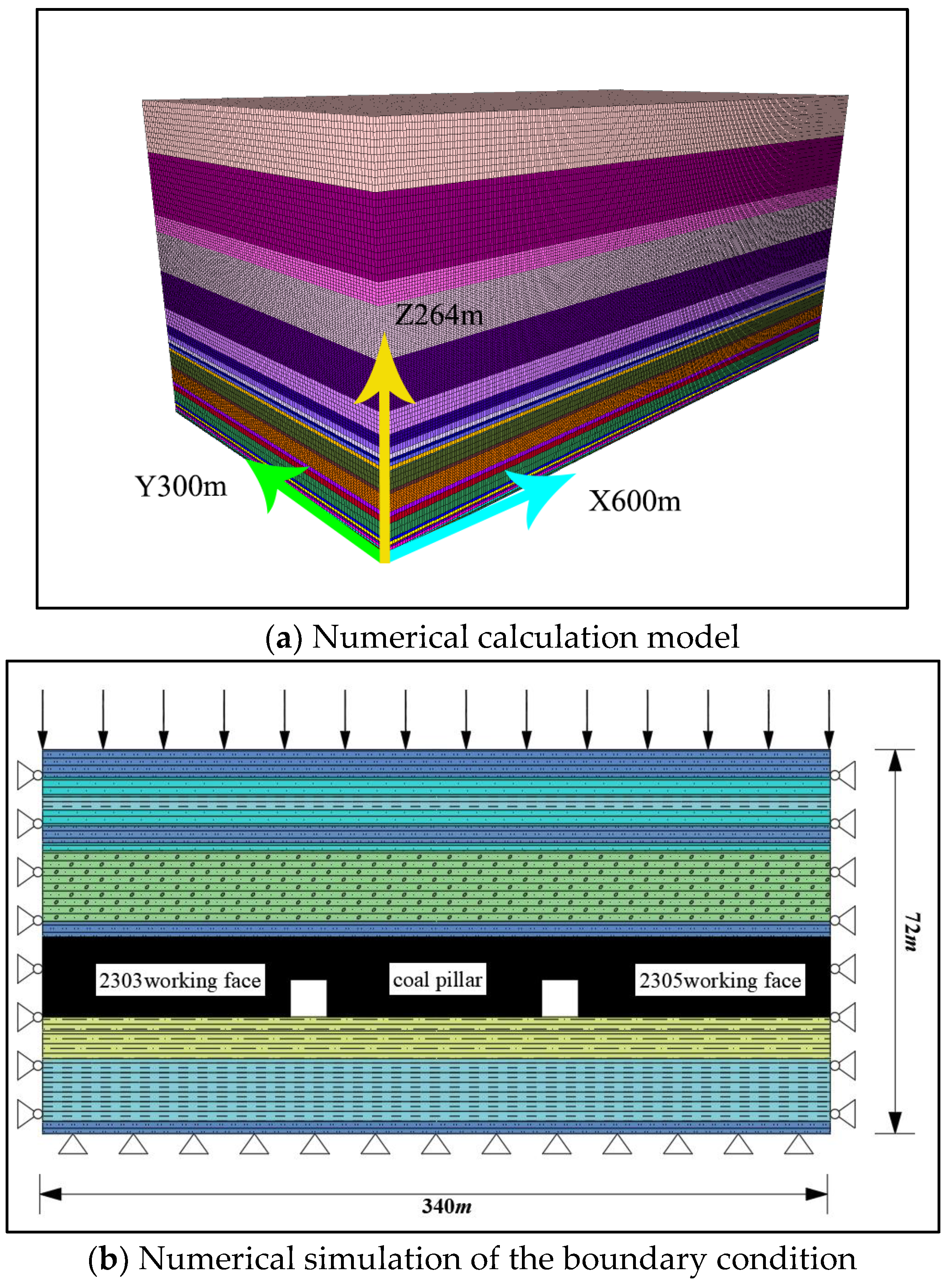
4.3.1. Modeling of Numerical Calculations

The following calculations can be used to make the numerical simulation results reflect the development height and law of the water-conducting fracture zone in the 2305 working face of the Cuijiagou coal mine. According to the actual mining conditions of the 2305 working face and the influence of the boundary effect, the model size X × Y × Z = 600 m × 300 m × 264 m was established. The left and right boundaries of the model each retained 60 m of coal pillars, and the width of the working face was 200 m; the initial computational model and the boundary condition are shown in Figure 8. The left, right, and lower boundaries of the model are displacement fixed constraint boundaries, and the upper boundary of the model applies the equivalent force of the unestablished rock layer, which takes the value of 9.43 MPa. The model parameters are shown in Table 3.

4.3.2. Numerical Simulation Scheme

During the mining process, the overlying rock in the goaf will collapse, fracture, and deform under its own weight and the pressure from the overlying strata. In the mining process, the vertical stress and plastic zone of the overburden rock above the working face were analyzed when the working face advanced 200 m.

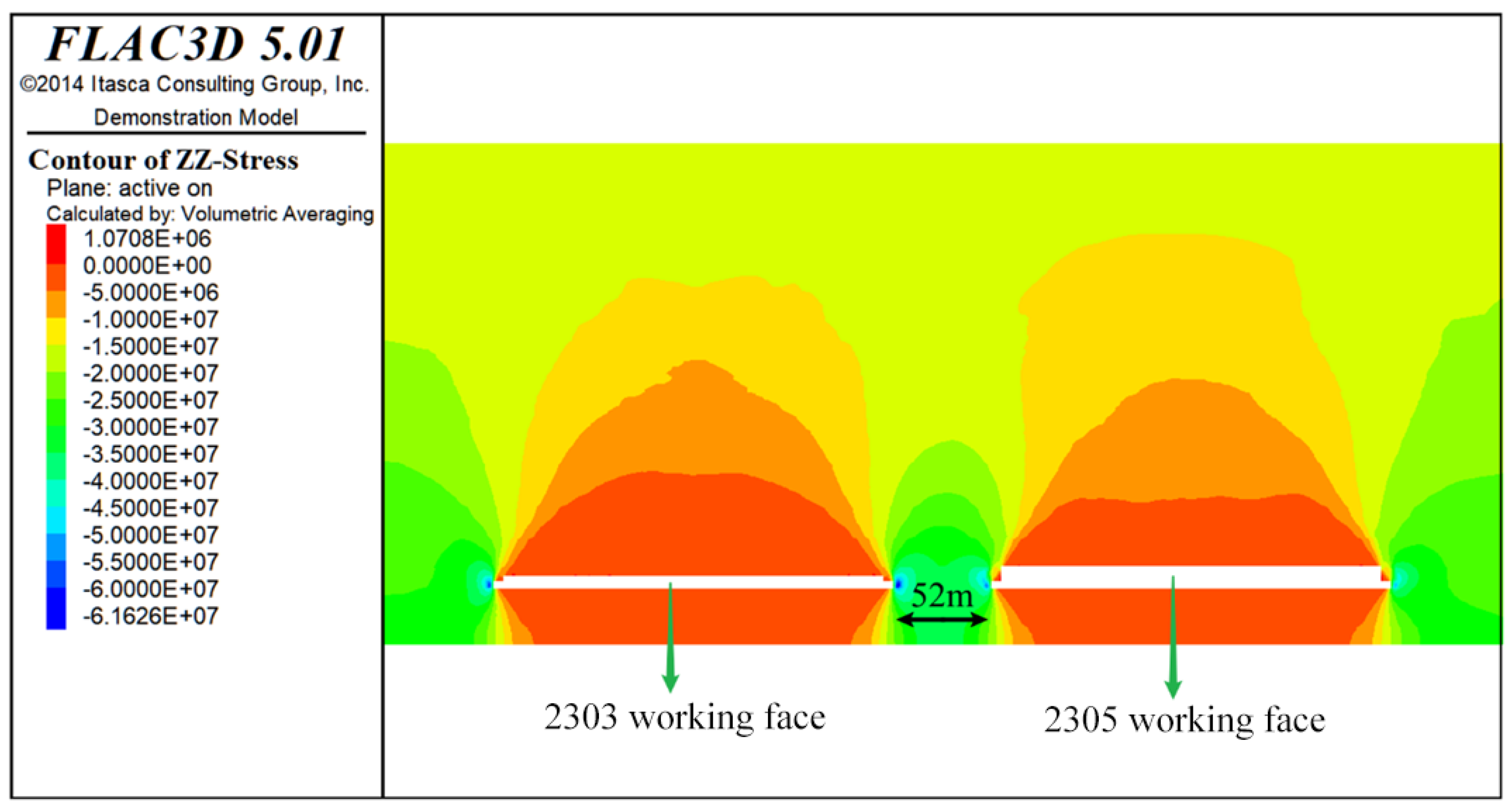
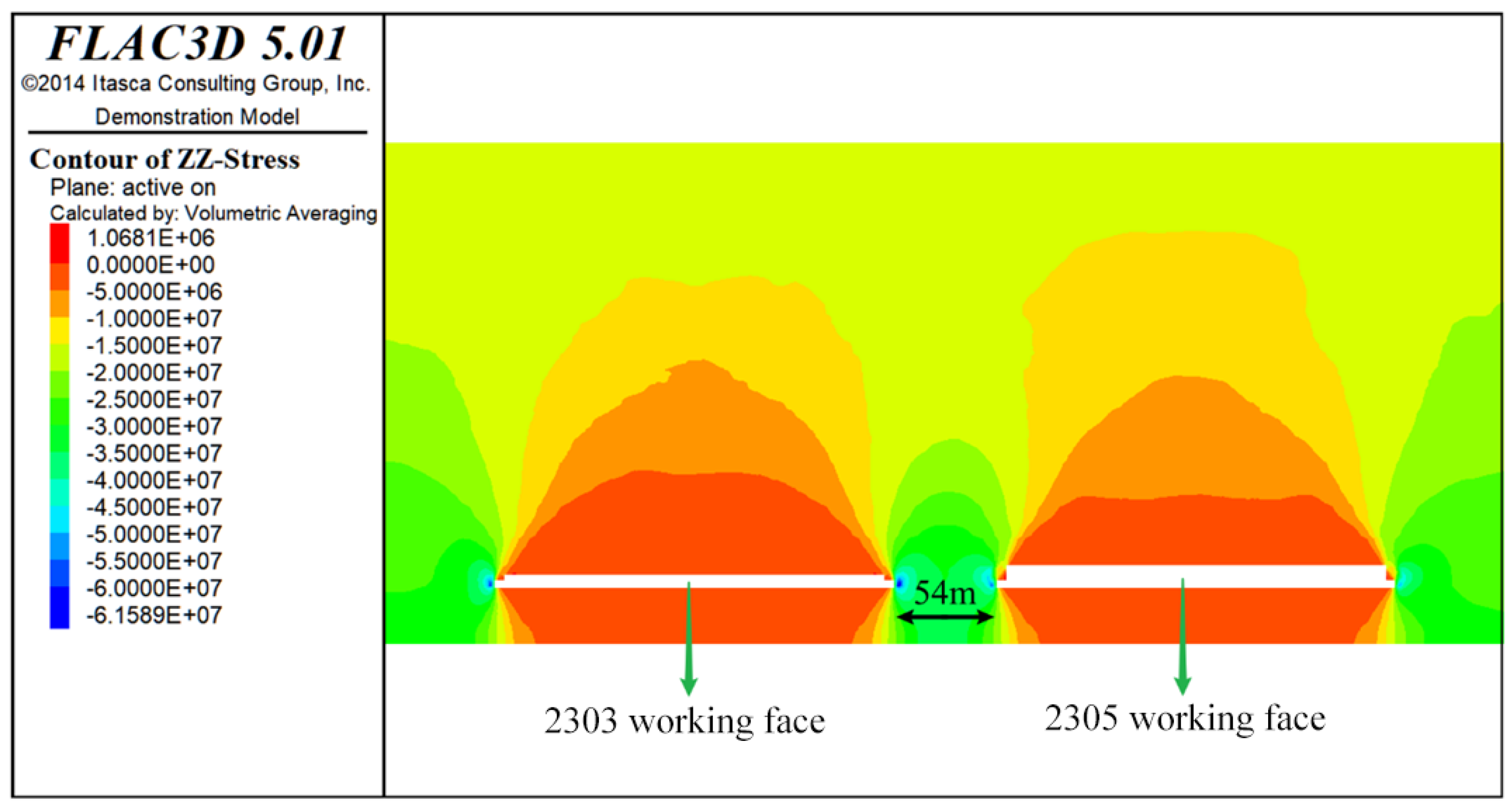
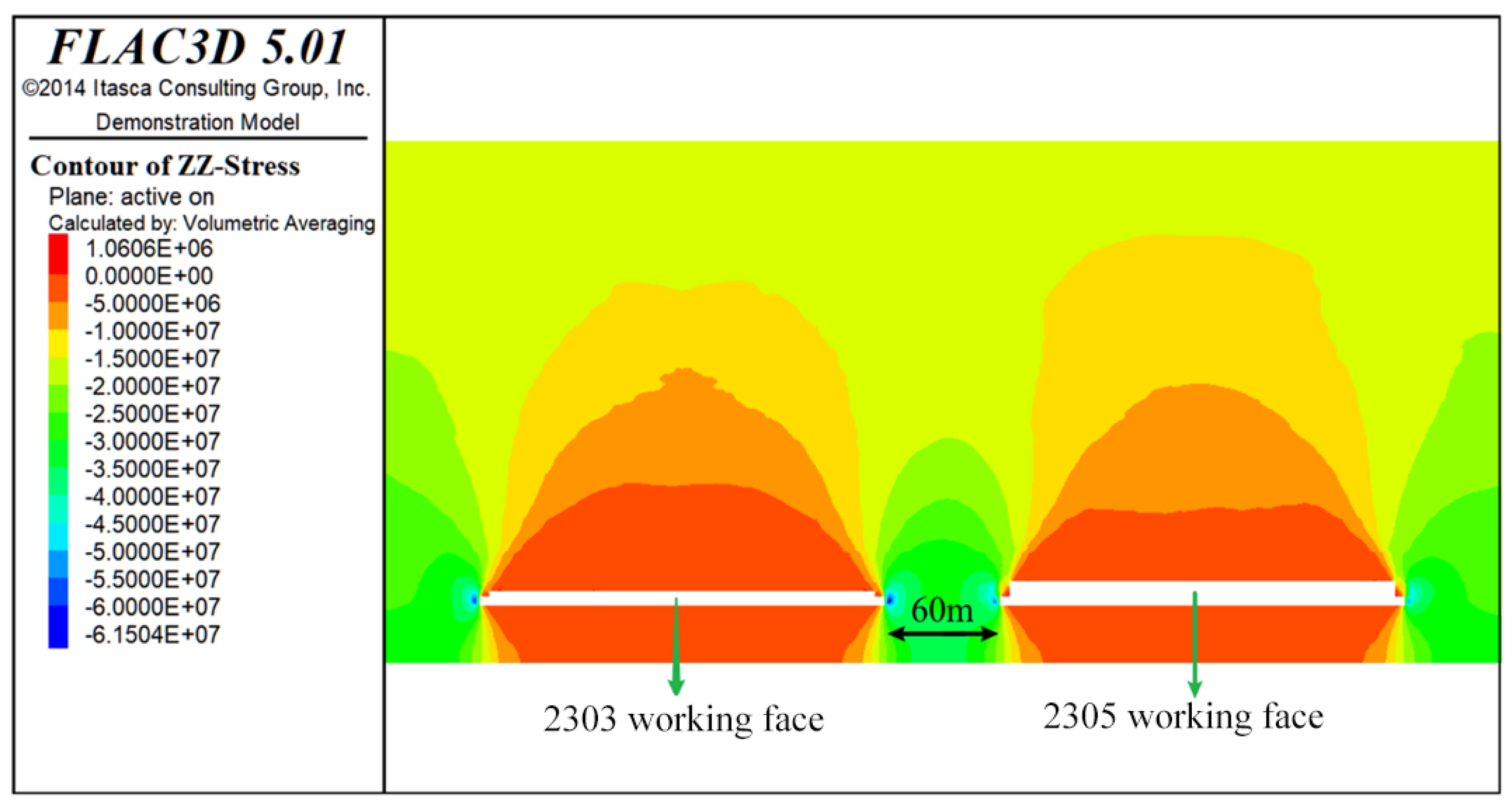
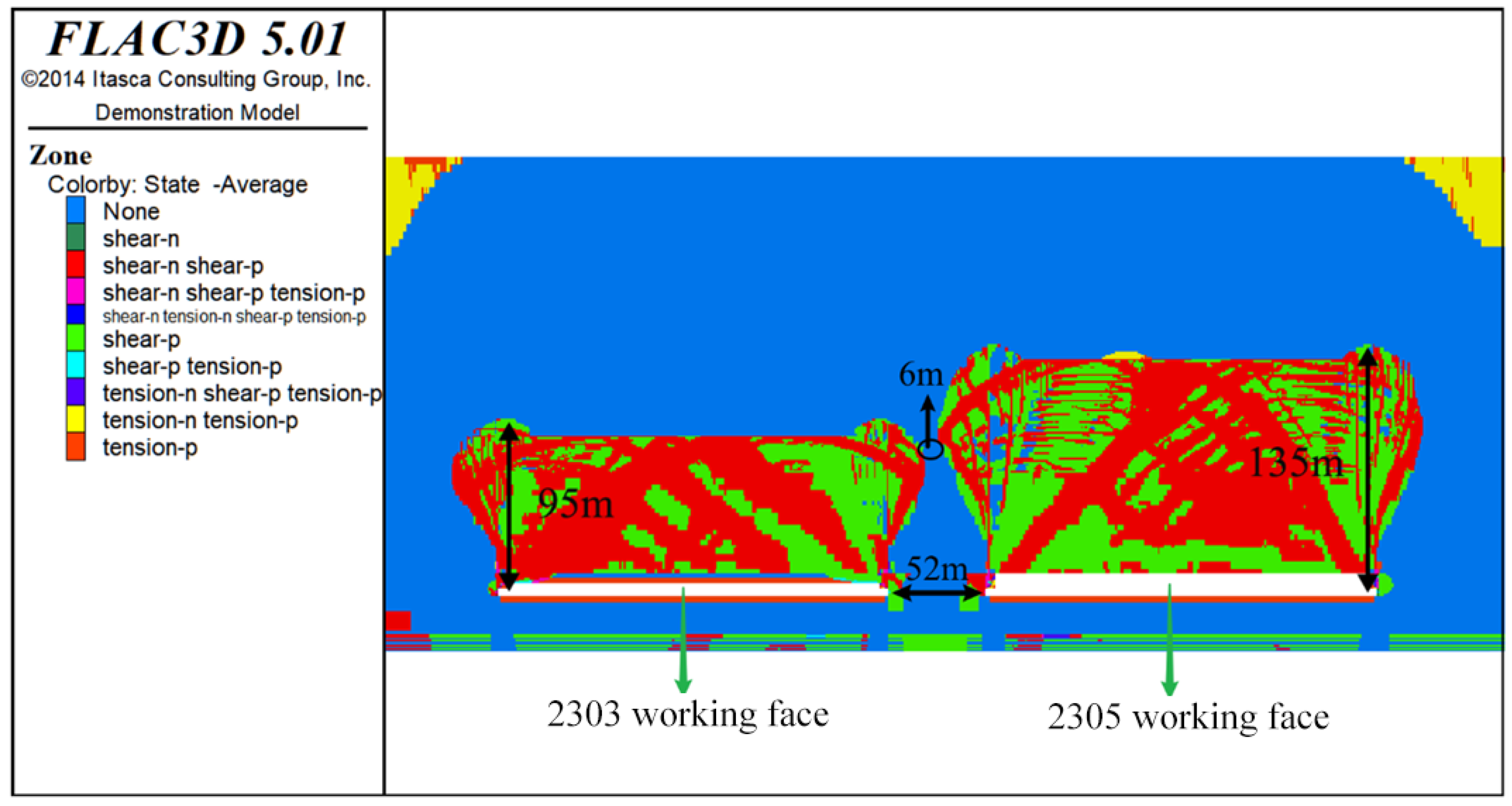
4.3.3. Numerical Simulation Results

An analysis was performed on the development height of the water conducting fracture zone and to determine whether the fracture zone above the coal pillar was connected in the 2303 and 2305 work faces. Therefore, the cross-section was obtained when the working face advanced 200 m to analyze the vertical stress distribution of the overlying rock above the face and the development of the plastic zone.
(1)
The analysis of the vertical stress distribution of overlying rock is shown in Figure 9, Figure 10 and Figure 11.
The vertical stress showed the same change in law under three kinds of coal pillar widths. After the coal seam is at the end of the mining stages, the roof strata above the working face goaf ruptures gradually under the mine pressure, and when the roof rock layer is not enough to support the pressure of the overlying rock, the roof rock layer will collapse, and the overlying rock stress in the goaf will be released to form a low-pressure area.
The vertical stress of the overlying rock above the goaf is symmetrically distributed and forms an arch. The vertical stress is mainly concentrated on both sides of the goaf, the side of the coal pillar, and the side of the coal seam.
When the widths of the coal pillar are 52 m, 54 m, and 60 m, the peak stresses in the coal pillar near the 2303 mining goaf are 61.1 MPa, 61.4 MPa, and 61.5 MPa, respectively, with an increase in the width of the coal pillar. The peak stress is stabilized at about 61 MPa; the peak stresses in the coal pillar at the side of the mining hollow area near the 2305 working face are 59.5 MPa, 59.3 MPa, and 57.1 MPa.
(2)
The analysis of the plastic zone distribution of the overlying rock is shown in Figure 12, Figure 13 and Figure 14.
After the mining stabilization of the 2303 and 2305 working faces, the damage mode of the overlying rock on the roof plate in the goaf is shear damage and tensile damage, and the development stops when the range of the plastic zone reaches a certain distance on both sides of the goaf.
Under three kinds of coal pillar widths, the maximum development height of the plastic damage zone in the 2303 workface is 95 m after the stabilization of the mining area, and the maximum development height of the plastic damage zone in the 2305 workface is 135 m, which is due to the different development heights of the water-conducting fracture zone caused by different mining heights of the two working faces.
In the transverse direction of the plastic damage range of the overlying rock above the goaf, when the widths of the coal pillar are 52 m, 54 m, and 60 m, there are 6 m, 9 m, and 15 m of elastic state rock above the coal pillar, respectively; thus, the plastic zone above the goaf of the two adjacent working faces of 2303 and 2305 has not been connected, which can effectively prevent the accumulation of water in the 2303 goaf.
In summary, through the analysis of overburden stress and plastic zone after the mining of the 2303 and 2305 working faces, the development heights of the water-conducting fracture zone after work face mining were 95 m and 135 m respectively, and there were elastic zones of 6 m, 9 m, and 15 m above the middle coal pillar of the two goaf zones. Therefore, it can be seen from the numerical simulation that the Cuijiagou Coal Mine can meet the safety production of the working face by retaining 52 m, 54 m, and 60 m coal pillars.

5. Analysis of the Geophysical Survey of the Working Face

5.1. Transient Electromagnetic Detection Technology Program

A YCS2000A mining transient electromagnetic instrument was used to detect the water richness in the lateral range of 100 m of the transporting channel of the 2305 comprehensive workface. A YCS 2000A mining transient electromagnetic instrument is shown in Figure 15.
The measuring points start from the intersection of the transportation channel and the cutting eye on the side of the 2305 working face near the mining area. One measuring point is arranged every 20 m in the direction of the stopping line, and the total length of the measuring line is 1460 m, over which each measuring point detects the inside of the interface pillar on the outside of the transportation channel in the directions of horizontal 0°, upward +45°, and upward +75°, respectively. The transient electromagnetic detection direction is shown in Figure 16. There are 74 measurement points and 222 measurement points arranged for this detection.

5.2. Interpretation and Analysis of Transient Electromagnetic Detection Results

Figure 17, Figure 18 and Figure 19 show the cross-sections of apparent resistivity contours in the horizontal +0°, upward 45°, and upward 75° directions on the headentry of the 2305 working face.
The results of probing in the horizontal +0° direction on the outside of the transportation parachute are shown in Table 4.
The results of probing in the upward +45° direction on the outside of the transportation parachute are shown in Table 5.
The results of probing in the +75° direction upward from the outside of the transportation parachute are shown in Table 6.
Table 4, Table 5 and Table 6 show that, except for some sections affected by transport, tunneling machines, and other metal interference in each direction of detection, the overall visual resistivity value changes are relatively smooth, and the detection results are more reliable. According to the size and distribution range of visual resistivity in each cross-section map, 15 Ω·m was taken as the boundary value of a low resistance anomaly area.
Due to the prevalence of metal bodies such as anchor rods, anchor nets, metal pipes, etc., in the exploration tunnel, the interpretation of the water richness of the geophysical survey anomaly area is more prone to interference, and the relatively low resistance zones existing in the sections of 0~120 m, 290~320 m, 390~400 m, 1140~1180 m, and 1410~1460 m at the location of excluded measurement points are presumed to be caused by the metal interference at the site, and they are not interpreted as aqueous zones.
The combined results of the three directions of detection and the locations of the measurement points 460~620 m, 670~820 m, 960~1020 m, and 1060~1180 m section are divided into a relatively low resistance anomaly area, which is thought to be caused by the impact of water accumulation in the goaf. The depth of influence is between 5~15 m, and the integrity of the coal pillar is good.

6. Conclusions

In this paper, the waterproof coal pillar retaining between the 2303 and 2305 working faces of Cuijiagou was studied. The calculation formula for the width of the waterproof coal pillar was derived and the development of the water conducting fracture zone of the overlying rock layer was analyzed. The rationality and safety of the waterproof coal pillar were comprehensively analyzed using a geophysical survey. The main conclusions are as follows:
(1)
According to the mechanical failure characteristics of the coal pillar under the conditions of water accumulation in the goaf, the waterproof coal pillar was divided into a water pressure damage zone, an elastic zone, and a plastic zone. The mechanical model of the coal pillar in different zones was established and the calculation formula of the width of the waterproof coal pillar was obtained. The parameters of the 2303 and 2305 working faces were included in the calculations to obtain the width of the coal pillar corresponding to the plastic zone, elastic area, and water pressure damage zone of the waterproof coal pillar, which were 14.26 m, 4.89 m, and 24.68 m, respectively. The theoretical width of the waterproof coal pillar was 44 m.
(2)
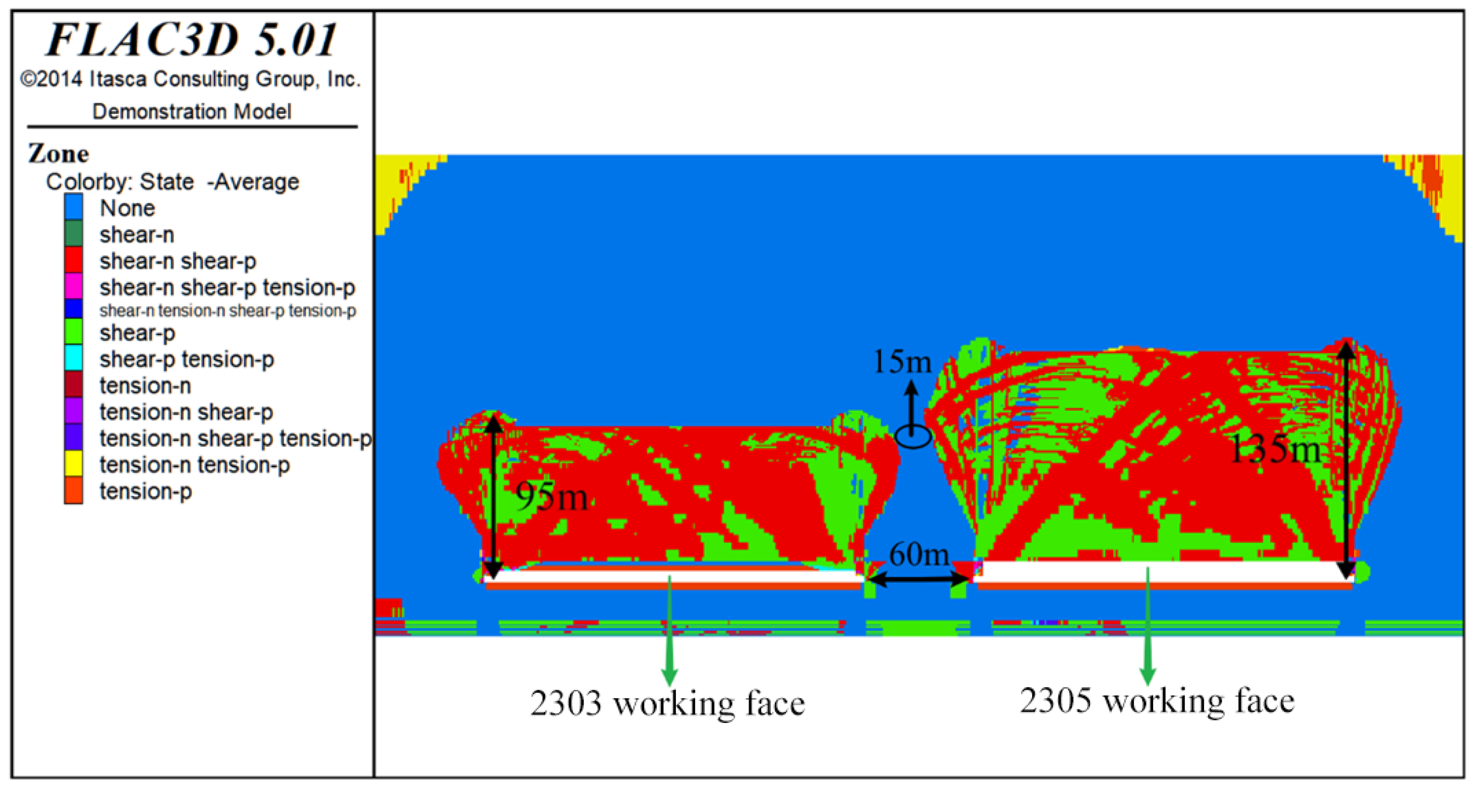
The numerical simulation method was used to analyze the development height of the water conducting fracture zone in the overlying rock strata when the actual coal pillar width between the working faces is 52 m, 54 m, and 60 m. The simulation results indicated that the development height of the water-conducting fracture zone of the 2303 and 2305 working faces is 95 m and 135 m, and there are elastic zones of 6 m, 9 m, and 15 m above the coal pillars in the middle of the goaf of the two working faces.
(3)
The transient electromagnetic method was used to detect the water richness of the actual coal pillar width between the 2303 and 2305 working faces, and the relatively low resistance areas in the sections of 0~120 m, 290~320 m, 390~400 m, 1140~1180 m, and 1410~1460 m at the measurement points were speculated to be caused by on-site metal interference. The 460~620 m, 670~820 m, 960~1020 m, and 1060~1180 m sections of the measuring points are divided into relatively low-resistance anomaly areas, which are inferred to be caused by the influence of water accumulation in the goaf. The depth of the influence of water accumulation in the goaf on the coal pillar is between 5~15 m, and the overall integrity of the coal pillar is good.

Author Contributions

Conceptualization, W.G.; methodology, W.G.; software, D.X.; validation, K.M. and D.X.; formal analysis, D.X. and Y.W.; investigation, D.X. and Y.W.; resources, W.G.; data curation, H.Z. and S.Y.; writing-original draft preparation, Z.H.; writing--review and editing, W.G.; visualization, D.X.; supervision, W.G.; project administration, W.G.; funding acquisition, W.G. All authors have read and agreed to the published version of the manuscript.

Funding

This research was funded by the National Natural Science Foundation of China, grant number 52274103.

Data Availability Statement

The raw data supporting the conclusions of this article will be made available by the authors on request. The data are not publicly available due to privacy.

Conflicts of Interest

The authors declare no conflicts of interest.

References

  1. Wang, C.; Wang, F.; Ye, Y.; Zhang, X.; Su, Y.; Jiang, L.; Li, Z.; Zhang, H. Evolutionary characteristics of coal consumption in China and its driving mechanism based on supply and demand perspectives. J. Nat. Resour. 2020, 35, 2708–2723. [Google Scholar]
  2. Chu, S.; Majumdar, A. Opportunities and challenges for a sustainable energy future. Nature 2012, 488, 294–303. [Google Scholar] [CrossRef] [PubMed]
  3. Yang, Y.; Liu, Y. Progress of world energy geography research and prospect of discipline development. Prog. Geosci. 2013, 32, 818–830. [Google Scholar]
  4. Dyczko, A. Real-time forecasting of key coking coal quality parameters using neural networks and artificial intelligence. Rud.-Geološko-Naft. Zb. 2023, 38, 105–117. [Google Scholar] [CrossRef]
  5. He, Z.; Zhou, Y.; Liu, Y. System dynamics simulation of China’s energy consumption structure in 2050: A transition scenario based on key industries. J. Nat. Resour. 2020, 35, 2696–2707. [Google Scholar]
  6. Li, Z. Research on the situation of coal industry and coal supply and demand in the 14th Five-Year Plan period. Coal Econ. Res. 2021, 41, 9–14. [Google Scholar]
  7. Miao, Q.; Meng, G.; Chen, M.; Ge, W.; Qu, J.; Wang, T. Coal resource availability analysis and guarantee study in China. Energy Environ. 2020, 6–8, 23. [Google Scholar] [CrossRef]
  8. Iordanov, I.; Buleha, I.; Bachurina, Y.; Boichenko, H.; Dovgal, V.; Kayun, O.; Kohtieva, O.; Podkopayev, Y. Experimental research on the haulage drifts stability in steeply dipping seams. Min Min. Depos. 2021, 15, 56–67. [Google Scholar] [CrossRef]
  9. Dychkovskyi, R.; Shavarskyi, I.; Saik, P.; Lozynskyi, V.; Falshtynskyi, V.; Cabana, E. Research into stress-strain state of the rock mass condition in the process of the operation of double-unit longwalls. Min Min. Depos. 2020, 14, 85–94. [Google Scholar] [CrossRef]
  10. Lu, C. Opening a New Era of Major Changes in China’s Energy System and Innovative Development of Clean and Renewable Energy—A Deep Understanding of the Great Historical Significance of Peak Carbon and Carbon Neutral Targets. People’s Forum-Acad. Front. 2021, 1, 28–41. [Google Scholar] [CrossRef]
  11. Sakhno, I.; Sakhno, S.; Skyrda, A. Field investigations of deformations in soft surrounding rocks of roadway with roof-bolting support by auger mining of thin coal seams. Rud.-Geološko-Naft. Zb. 2022, 37, 23–38. [Google Scholar] [CrossRef]
  12. Tian, Y.; Zhang, P.; Wu, R.; Liu, C. Current analysis and prospect of fault activation research under coal mining conditions. Coalf. Geol. Explor. 2021, 49, 60–70. [Google Scholar] [CrossRef]
  13. Zhienbayev, A.; Balpanova, M.; Asanova, Z.; Zharaspaev, M.; Nurkasyn, R.; Zhakupov, B. Analysis of the roof span stability in terms of room-and-pillar system of ore deposit mining. Min Min. Depos. 2023, 17, 129–137. [Google Scholar] [CrossRef]
  14. Lozynskyi, V.; Medianyk, V.; Saik, P.; Rysbekov, K.; Demydov, M. Multivariance solutions for designing new levels of coal mines. Rud.-Geološko-Naft. Zb. 2020, 35, 23–31. [Google Scholar] [CrossRef]
  15. Ren, X. Research on Characteristics and Prevention and Control of Coal Mine Geological Hazards. Contemp. Chem. Res. 2019, 17, 65–66. [Google Scholar] [CrossRef]
  16. Chen, P.P.; Liu, H.Q.; Zhang, G.Y. Determination of waterproof rock pillar height with the top coal caving under sea. Meitan Xuebao/J. China Coal Soc. 2009, 34, 875–880. [Google Scholar]
  17. Nguyen, L.Q.; Le, T.T.T.; Nguyen, T.G.; Tran, D.T. Prediction of underground mining-induced subsidence: Artificial neural network based approach. Min Min. Depos. 2023, 17, 45–52. [Google Scholar] [CrossRef]
  18. Qing, L. Reasonable Width of Waterproof Coal Pillar under the Condition of Different Fault Dip Angles. J. Min. Saf. Eng. 2009, 26, 179–183. [Google Scholar]
  19. Babets, D.; Sdvyzhkova, O.; Hapieiev, S.; Shashenko, O.; Vasyl, V. Multifactorial analysis of a gateroad stability at goaf interface during longwall coal mining—A case study. Min Min. Depos. 2023, 17, 9–19. [Google Scholar] [CrossRef]
  20. Smoliński, A.; Malashkevych, D.; Petlovanyi, M.; Rysbekov, K.; Lozynskyi, V.; Sai, K. Research into Impact of Leaving Waste Rocks in the Mined-Out Space on the Geomechanical State of the Rock Mass Surrounding the Longwall Face. Energies 2022, 15, 9522. [Google Scholar] [CrossRef]
  21. Sharipov, A.; Adoko, A. An approach to estimate coal pillar strength. IOP Conf. Ser. Earth Environ. Sci. 2021, 833, 12136. [Google Scholar] [CrossRef]
  22. Shavarskyi, I.; Falshtynskyi, V.; Dychkovskyi, R.; Akimov, O.; Sala, D.; Buketov, V. Management of the longwall face advance on the stress-strain state of rock mass. Min Min. Depos. 2022, 16, 78–85. [Google Scholar] [CrossRef]
  23. Hejmanowski, R.; Witkowski, W.T. Suitability assessment of artificial neural network to approximate surface subsidence due to rock mass drainage. J. Sustain. Min. 2015, 14, 101–107. [Google Scholar] [CrossRef]
  24. Tan, X.; Song, B.; Bo, H.; Li, Y.; Wang, M.; Lu, G. Extraction of Irregularly Shaped Coal Mining Area Induced Ground Subsidence Prediction Based on Probability Integral Method. Appl. Sci. 2020, 10, 6623. [Google Scholar] [CrossRef]
  25. Deng, X.; Han, M.; Meng, B. Discussion on the principle and calculation method of retaining waterproof coal rock pillars. Coal Technol. 2001, 20, 30–33, 34. [Google Scholar] [CrossRef]
  26. Liu, Y.; Chai, X.; Li, J. Optimization of waterproof coal rock columns in adjacent working faces. J. Coal Sci. 2009, 34, 239–242. [Google Scholar] [CrossRef]
  27. Liu, Y.; Wu, Y.P.; Wang, Y.S. Study on the reasonable width of waterproof coal pillar in the upper disk of fault. J. Xi’an Univ. Sci. Technol. 2010, 30, 523–530. [Google Scholar] [CrossRef]
  28. Liu, C.; Ding, K. On the critical size of underground watertight coal column for pressure damage. J. Coal 2001, 26, 632–636. [Google Scholar] [CrossRef]
  29. Yao, Z. Exploration on setting waterproof coal pillar in 14-coal mining face of Shengli coal mine. Sci. Technol. Wind. 2021, 133–134. [Google Scholar] [CrossRef]
  30. Xie, H. Retention of waterproof coal pillar for mining thick coal seam outcrop area under giant thick red seam. Coal Mine Saf. 2020, 51, 201–204. [Google Scholar]
  31. Wan, Z.; Xing, W. Research on Optimization Design of Waterproof Coal Pillar in Mine. Inn. Mong. Coal Econ. 2018, 3, 126–127. [Google Scholar] [CrossRef]
  32. Du, S.; Lian, F.; Zhang, Y.T. Research on waterproof coal (rock) pillar retention for mining under thick loose layer in Liuzhuang coal mine. Coal Sci. Technol. 2018, 46, 30–33. [Google Scholar]
  33. Wang, R.; Meng, Z.; Xie, X.; Jia, L.; Wang, Y. Rational placement and numerical simulation of waterproof coal pillars under huge-thick loose beds. Coalf. Geol. Explor. 2011, 39, 31–35. [Google Scholar] [CrossRef]
  34. Wang, G.-C.; An, X. Waterproof Coal Pillar Retention Methods under Thick Loose Alluvial Seam. In Proceedings of the 7th Coal Science and Technology Conference, Beijing, China, 17 April 2011; p. 8. [Google Scholar]
  35. An, X. Retention method of waterproof coal pillars in thick loose alluvium. Hydraul. Coal Min. Pipeline Transp. 2010, 2, 67–69. [Google Scholar] [CrossRef]
  36. Jiang, W. Coal body damage characteristics and control mechanism of shallow buried hard coal roadway. Coal Mine Saf. 2021, 52, 207–213. [Google Scholar] [CrossRef]
  37. Fang, G.; Liu, Y.; Li, A. Stability evaluation of coal pillar in working face of shallow buried coal seam in Shenfu mine. Coal Min. 2019, 24, 56–61. [Google Scholar] [CrossRef]
Figure 1. Cuijiagou Coal Mine Location Map and 2305 Working Face Location Map.
Applsci 14 00884 g001
Figure 2. Comprehensive histogram of coal and rock of the 2305 working face.
Applsci 14 00884 g002
Figure 3. Water accumulation pressure distribution of the 2305 working face.
Applsci 14 00884 g003
Figure 4. Schematic structure and force of the waterproof coal pillar by section.
Applsci 14 00884 g004
Figure 5. Mechanical calculation model of the width of the plastic zone.
Applsci 14 00884 g005
Figure 6. Mechanical calculation model of the coal pillar width in the elastic area.
Applsci 14 00884 g006
Figure 7. Mechanical calculation model of the coal pillar width in the water pressure damage zone.
Applsci 14 00884 g007
Figure 8. Initial computational model.
Applsci 14 00884 g008
Figure 9. Vertical stress distribution of overburden rock at 52 m width of the coal pillar (Unit: Pa).
Applsci 14 00884 g009
Figure 10. Vertical stress distribution of overburden rock at 54 m width of the coal pillar (Unit: Pa).
Applsci 14 00884 g010
Figure 11. Vertical stress distribution of overburden rock at 60 m width of the coal pillar (Unit: Pa).
Applsci 14 00884 g011
Figure 12. Plastic zone distribution of overburden rock at 52 m width of the coal pillar.
Applsci 14 00884 g012
Figure 13. Plastic zone distribution of overburden rock at 54 m width of the coal pillar.
Applsci 14 00884 g013
Figure 14. Plastic zone distribution of overburden rock at 60 m width of coal the pillar.
Applsci 14 00884 g014
Figure 15. YCS2000A Mining Transient Electromagnetic Meter.
Applsci 14 00884 g015
Figure 16. Schematic of the transient electromagnetic detection direction.
Applsci 14 00884 g016
Figure 17. Apparent resistivity contour cross-section in the horizontal +0° direction (Blue = [5, 15], Green = [15, 45], Yellow = [45, 65], Red = [65, 85], White = [85, 95], and unit: Ω·m).
Applsci 14 00884 g017
Figure 18. Section of apparent resistivity contours in the +45° direction (Blue = [5, 15], Green = [15, 45], Yellow = [45, 65], Red = [65, 85], White = [85, 95], and unit: Ω·m).
Applsci 14 00884 g018
Figure 19. Section of apparent resistivity contours in the +75° direction (Blue = [5, 15], Green = [15, 45], Yellow = [45, 65], Red = [65, 85], White = [85, 95], and unit: Ω·m).
Applsci 14 00884 g019
Table 1. Statistics of water accumulation pressure in different areas of the 2305 working face.
Area Number1234
2305 Length of working face/m0~800800~10151015~10841084~1540
Width of coal pillar/m60545254
Ponding pressure/MPa1.06~0.60.6~0.360.36~0.30.3~0
Table 2. Calculation results of the waterproof coal pillar width.
Sector NumberSector ISector IISector IIISector IV
K4444
M/m12121212
p/MPa1.060.60.360.3
Kp/MPa0.940.940.940.94
L/m44.133.225.723.5
Actual width/m60545254
Table 3. Model Parameters.
Lithologyρ/kg·m−3K/GPaG/GPaφC/MPaσp/MPa
Mudstone26358.775.7725.36.31.75
Sandy mudstone26688.754.0428.908.81.44
Carbonaceous mudstone26608.653.526.907.81.4
4-2# coal14186.272.41303.00.94
Siltstone26936.485.0931.51.57.53
Coarse-grained sandstone26737.134.6431.79.74.75
Medium-grained sandstone26737.134.6431.77.75.26
Table 4. Detection results in +0° direction on the outside of the transportation roadway.
NumberLow Resistance AreaInterpretation for Results
10~120 mThe apparent resistivity is very low, analyzed as an effect of the transports and rails, and not interpreted as a water anomaly.
2290~320 mThe low apparent resistivity is an effect of the drilling machine and is not interpreted as a water-bearing anomaly.
3390~400 mThe low apparent resistivity is an effect of the rails in the field and is not interpreted as a water anomaly.
4460~620 m
(Probing depth: 45~100 m)
Presumed to be a relatively low resistance area.
5670~820 m
(Probing depth: 40~100 m)
Presumed to be a relatively low resistance area.
61000~1020 m
(Probing depth: 50~100 m)
Presumed to be a relatively low resistance area.
71070~1120 m
(Probing depth: 40~100 m)
Presumed to be a relatively low resistance area.
81140~1180 mThe apparent resistivity is very low, analyzed as an effect of the tunneling machine, and not interpreted as a water anomaly.
91410~1460 mThe apparent resistivity is very low, analyzed as an effect of the steel tube, and not interpreted as a water anomaly.
Table 5. Detection results in the +45° direction on the outside of the transportation roadway.
NumberLow Resistance AreaExplanation for Results
10~120 mThe apparent resistivity is very low, analyzed as an effect of the transports and rails, and not interpreted as a water anomaly.
2290~320 mThe low apparent resistivity is an effect of the drilling machine and is not interpreted as a water-bearing anomaly.
3390~400 mThe low apparent resistivity is an effect of the rails in the field and is not interpreted as a water anomaly.
4710~730 m
(Probing depth: 50~100 m)
Presumed to be a relatively low resistance area.
5770~810 m
(Probing depth: 40~100 m)
Presumed to be a relatively low resistance area.
61000~1020 m
(Probing depth: 65~100 m)
Presumed to be a relatively low resistance area.
71060~1120 m
(Probing depth: 40~100 m)
Presumed to be a relatively low resistance area.
81140~1180 mThe apparent resistivity is very low, analyzed as an effect of the tunneling machine, and not interpreted as a water anomaly.
91410~1460 mThe apparent resistivity is very low, analyzed as an effect of the steel tube, and not interpreted as a water anomaly.
Table 6. Detection results in the +75° direction on the outside of the transportation roadway.
NumberLow Resistance AreaExplanation for Results
10~120 mThe apparent resistivity is very low, analyzed as an effect of the transports and rails, and not interpreted as a water anomaly.
2290~320 mThe low apparent resistivity is an effect of the drilling machine and is not interpreted as a water-bearing anomaly.
3390~400 mThe low apparent resistivity is an effect of the rails in the field and is not interpreted as a water anomaly.
4710~730 m
(Probing depth: 40~100 m)
Presumed to be a relatively low resistance area.
5960~1010 m
(Probing depth: 55~100 m)
Presumed to be a relatively low resistance area.
61060~1130 m
(Probing depth: 40~100 m)
Presumed to be a relatively low resistance area.
71140~1180 mThe apparent resistivity is very low, analyzed as an effect of the tunneling machine, and not interpreted as a water anomaly.
81410~1460 mThe apparent resistivity is very low, analyzed as an effect of the steel tube, and not interpreted as a water anomaly.
Disclaimer/Publisher’s Note: The statements, opinions and data contained in all publications are solely those of the individual author(s) and contributor(s) and not of MDPI and/or the editor(s). MDPI and/or the editor(s) disclaim responsibility for any injury to people or property resulting from any ideas, methods, instructions or products referred to in the content.

