Article

Development of Circuits for Antilogarithmic Converters with Efficient Error–Area–Delay Product Using the Fractional-Bit Compensation Scheme for Digital Signal Processing Applications

Department of Electrical Engineering, National Quemoy University, Kinmen 89250, Taiwan
Appl. Sci. 2024, 14(4), 1487; https://doi.org/10.3390/app14041487
Submission received: 31 December 2023 / Revised: 5 February 2024 / Accepted: 9 February 2024 / Published: 12 February 2024
(This article belongs to the Topic Innovation of Applied System)

Abstract

:
Digital signal processing (DSP) has been widely adopted in sensor systems, communication systems, digital image processing, artificial intelligence, and Internet of Things applications. However, these applications require circuits for complex arithmetic computation. The logarithmic number system is a method to reduce the implementation area and transmission delay for arithmetic computation in DSP. In this study, we propose antilogarithmic converters with efficient error–area–delay products (eADPs) based on the fractional-bit compensation scheme. We propose three mathematical approximations—case 1, case 2, and case 3—to approximate the accurate antilogarithmic curve with different DSP requirements. The maximum percentage errors of conversion for case 1, case 2, and case 3 are 1.9089%, 1.7330%, and 1.2063%, respectively. Case 1, case 2, and case 3 can achieve eADP savings of 15.66%, 80.80%, and 84.61% compared with other methods reported in the literature. The proposed eADP-efficient antilogarithmic converters can achieve lower eADP and digitalized circuit implementation. The hardware implementation utilizes Verilog Hardware Description Language and the digital circuits are created via very-large-scale integration by the Taiwan Semiconductor Manufacturing Company with 0.18 µm CMOS technology. This proposed antilogarithmic converter can be efficiently applied in DSP.

1. Introduction

Digital signal processing (DSP) has been widely adopted in the Internet of Things (IoT), sensor systems, communication systems, digital image processing, and artificial intelligence (AI). Mobile handheld electronic devices, such as mobile phones, tablets, and notebooks, involve new technology and applications such as three-dimensional computer graphics and real-time systems in DSP. These require circuits for complex arithmetic computations such as multiplication, division, square root, squaring, and powering, which entail additional hardware costs and longer latency. To reduce the hardware costs and transmission delays, recent studies have developed novel methods to replace the complex arithmetic computations, such as the CORDIC algorithm [1], the table-based algorithm using rectangular multipliers [2], and the logarithmic number system (LNS) [3,4,5,6,7,8,9,10,11,12,13,14,15,16,17,18,19,20,21,22] to handle arithmetic computations. The CORDIC algorithm [1] uses an iterative method, and is not suitable for three-dimensional real-time DSP because of the limitation of operation speed. The table-based algorithm using rectangular multipliers [2] requires quite a large hardware memory for storage. The logarithmic number system (LNS) [3,4,5,6,7,8,9,10,11,12,13,14,15,16,17,18,19,20,21,22] reduces the implementation area and transmission delay for arithmetic computations in DSP. LNS-based arithmetic computation can simplify the complex operations by transforming multiplication to addition, division to subtraction, square root to right shifts, squaring to left shifts, powering to continuous addition, and reciprocals to complementing. Table 1 shows the LNS-based operations.
The LNS consists of three main units: the logarithmic converter, simple arithmetic unit (SAU), and antilogarithmic converter, as shown in Figure 1. The logarithmic converter is used to convert two binary inputs (e.g., a and b in Table 1) into the logarithmic system format (log2 a and log2 b). The SAU uses the shifter, complement, adder, or subtractor operations to perform a simple mathematical computation in the logarithmic system format. The antilogarithmic function is used to convert the final arithmetic computation result of the logarithmic system and simple arithmetic unit into a fixed-point binary output. The present study focuses on antilogarithmic converters with efficient error–area–delay products (eADPs) using the fractional-bit compensation schemes.
In recent years, many schemes have been proposed for antilogarithmic conversion systems, such as the straight-line method [3], look-up table method [7,15], shift-and-add method [5,11], bit correction scheme [13], and constant compensation scheme [16]. In 1962, Mitchell [3] first used an approximation method to approximate the antilogarithmic converter, which adopted out = 1 + m to approximate an out = 2m curve. Although this method produces considerably large antilogarithmic conversion, it is simple and uses little hardware area. Nam et al. [7,15] used the look-up read-only memory (ROM) method to implement the antilogarithmic converter. This method obtains highly accurate antilogarithmic conversion values from the SAU and logarithmic converter. However, the look-up table scheme demands additional hardware area. Abed and Siferd [5] and Loukrakpam and Choudhury [11] used the shift-and-add scheme to approximate an out = 2m curve. This method improved the performance in terms of the approximation error, hardware area, and delay, though it had further scope for improvement. Juang et al.’s [13] bit-correction scheme to approximate antilogarithmic conversion showed considerable scope for improvement in approximation error. Kuo and Juang [16] proposed the constant compensation scheme to approximate an out = 2m curve, which had scope of improvement in terms of hardware cost and latency. The above-mentioned shift-and-add method, bit correction scheme, and constant compensation scheme are ROM-free, and use mathematical function mapping to replace the look-up table method. However, the performance of these methods is not efficient enough for the design of antilogarithmic converters. The proposed eADP-efficient antilogarithmic converters based on the fractional-bit compensation scheme is expected to achieve high performance, considerably low approximation error, small hardware area, and short latency.
This paper is organized as follows. The methods reported in the literature are described in Section 2. The algorithm for the converter design incorporating the proposed eADP-efficient antilogarithmic converter is described in Section 3. Section 4 presents the results and comparisons of the various methods. Finally, the conclusions are presented in Section 5.

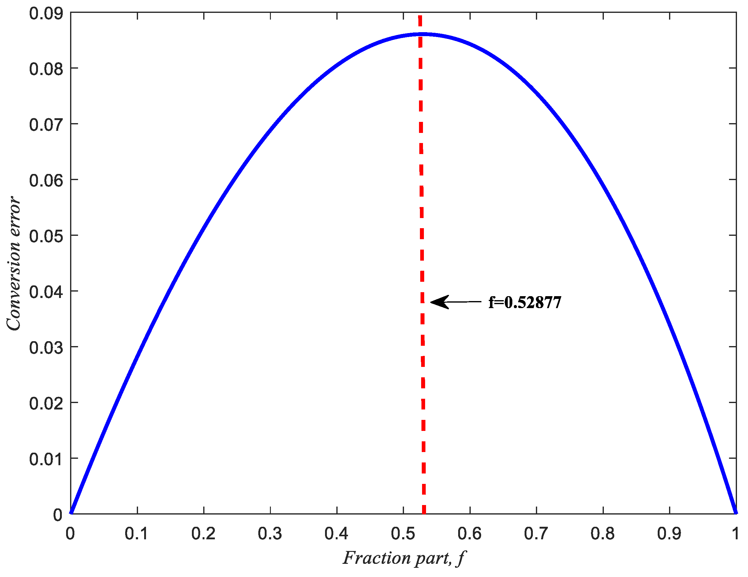
2. Antilogarithmic Conversion Methods

For antilogarithmic conversion, out = 2m, m can be written as m = i + f, where i denotes the integer part and f is the fraction part. Thus, 2m = 2(i+f) = 2i2f. For simplified computation, consider the integer part i to be zero and the fraction part f to be between 0 and 1 ( 0 f < 1 ). Taking 20.4 as an example, let the input value be 0.4 = 0 + 0.4, where i = 0 and f = 0.4. The output will be 20.4 = 20  × 20.4 = 20.4 1.319. In 1962, Mitchell [3] proposed out = 1 + f to approximate 2f. This method is quite simple and has quite a low hardware cost. However, it produces a large approximation error. The maximum approximation error occurs at f = 0.52877, as shown by:
difference ( f ) = [ ( 1 + f ) 2 f ]
d d f difference ( f ) = d d f [ ( 1 + f ) 2 f ] = 1 ln 2 × 2 f
L e t   1 ln 2 × 2 f = 0 ,   2 f = 1 ln 2 ,   f = 1 ln 2 × ln ( 1 ln 2 ) 0.52877
The conversion error of Mitchell’s [3] straight-line out = 1 + f and the accurate antilogarithmic curve out = 2f are shown in Figure 2.
Over the past sixty years, many antilogarithmic conversion methods have been developed to improve the performance of approximation, latency, and hardware area for antilogarithmic converters. Among them, Abed and Siferd’s shift-and-add scheme [5], Nam et al.’s ROM-based look-up table [7,15], Juang et al.’s bit correction scheme [13], Kuo and Juang’s constant compensation scheme [16], and Loukrakpam and Choudhury’s shift-and-add method [11] are some of the most efficient methods. In 2003, Abed and Siferd [5] proposed antilogarithmic converters with two-region, six-region, and seven-region shift-and-add linear approximation methods to reduce antilogarithmic conversion errors. Their two-region equation is:
Y = 2 m { [ m + 3 16 × m 7 M S B i t s ¯ + 13 16 + 1 1024 + 1 2048 ] ,   0 m < 0.5 ; [ m + ( 3 16 ) × m 7 M S B i t s + 13 16 ] ,   0 . 5 m 1 ;
where m q M S B i t s ¯ is represented as 1 − mqMSBits − (1/2q) and mqMSBits is the first q most significant bits after the point of binary input.
The mathematical model of Loukrakpam and Choudhury’s [11] two-region shift-and-add scheme is:
Y = 2 f { [ f ( 1 8 + 1 32 + 1 64 ) × f 7 M S B i t s + 2047 2048 ] ,   0 f < 0.5 ; [ f + ( 1 8 + 1 32 + 1 64 ) × f 7 M S B i t s + 1696 2048 ] ,   0 . 5 f 1 ;
The mathematical model of Juang et al.’s [13] bit correction scheme is:
Y = 2 m { [ 1 + m ( m 2 16 + m 3 ¯ m 2 ¯ 32 + m 4 64 + m 3 128 ) ] ,   0 m < 0.5 ; [ 1 + m ( m 2 ¯ 16 + m 3 m 2 ¯ ¯ 32 + m 4 ¯ 64 + m 3 ¯ 128 ) ] ,   0 . 5 m 1 ;
where is the logic OR gate and is the logic AND gate. For the antilogarithmic converter’s constant compensation scheme, Kuo and Juang’s [16] 14-region constant compensation scheme is given by:
Y = 2 m { [ 1 + m ] ,   0 m < 1 32 ; [ 1 + m ( 1 128 ) ] ,   1 32 m < 2 32 ; [ 1 + m ( 2 128 ) ] ,   2 32 m < 3 32 ; [ 1 + m ( 3 128 ) ] ,   3 32 m < 4 32 ; [ 1 + m ( 4 128 ) ] ,   4 32 m < 5 32 ; [ 1 + m ( 5 128 ) ] ,   5 32 m < 6 32 ; [ 1 + m ( 6 128 ) ] ,   6 32 m < 8 32 ; [ 1 + m ( 8 128 ) ] ,   8 32 m < 12 32 ; [ 1 + m ( 10 128 ) ] ,   12 32 m < 22 32 ; [ 1 + m ( 8 128 ) ] ,   22 32 m < 24 32 ; [ 1 + m ( 7 128 ) ] ,   24 32 m < 26 32 ; [ 1 + m ( 5 128 ) ] ,   26 32 m < 28 32 ; [ 1 + m ( 3 128 ) ] ,   28 32 m < 30 32 ; [ 1 + m ] ,   30 32 m < 1 ;
The antilogarithmic conversion methods in the literature still have scope for improvement in terms of the approximation error, area cost, and delay time of antilogarithmic conversion. The eADP-efficient antilogarithmic converter using the fractional-bit compensation scheme proposed in this study is expected to minimize the approximation error, area cost, and delay time further. Section 3 describes the proposed algorithm of the fractional-bit compensation.

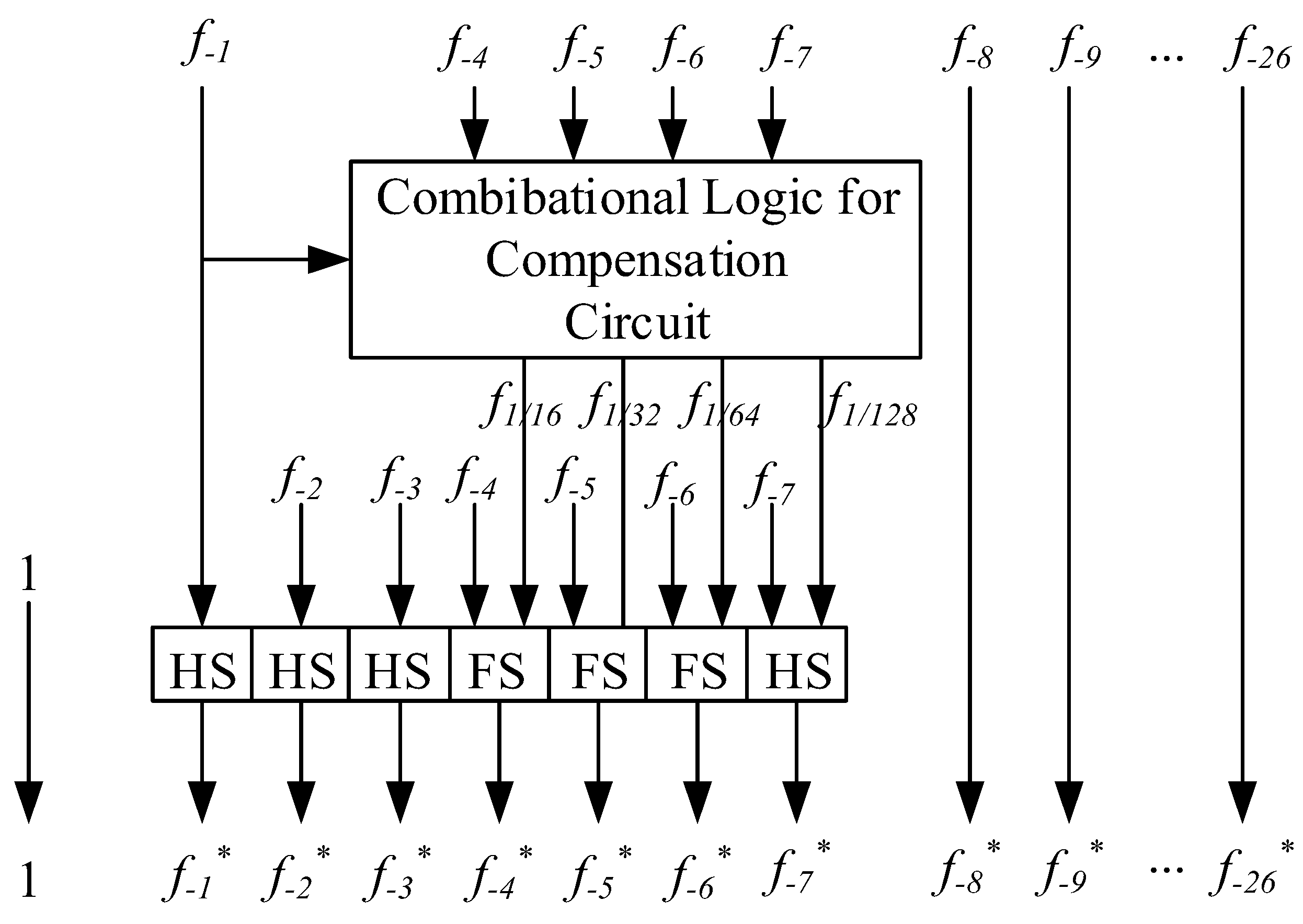
3. Proposed Algorithm for Fractional-Bit Compensation

This section discusses the proposed eADP-efficient antilogarithmic converters using the fractional-bit compensation schemes. To design an efficient antilogarithmic converter, we first compare Mitchell’s [3] straight-line out = 1 + f with the accurate antilogarithmic curve out = 2f and analyze the percentage conversion error, as shown in Figure 3 and Figure 4, respectively. The percentage conversion error is defined as 100% × (conversion error divided by 2f):
  Percentage   Conversion   Error   = Conversion   Error 2 f = ( ( 1 + f ) 2 f ) 2 f × 100 %   ,   0 f < 1
The maximum percentage error is defined as 100% × (sum of absolute value of maximum positive percentage error and minimum negative percentage error):
Maximum   Percentage   Error   = ( | Maximum   positive   percentage   error | + | Minimum   negative   percentage   error | 2 f ) × 100 %   ,   0 f < 1
For the fractional-bit compensation method, we found that the first region and the last region could not be compensated by Figure 3. The compensated region is divided by the 2n region, where n denotes the first most significant bits (MSB). For example, n = 4 is divided by 16 compensated regions. That is, f−1, f−2, f−3, and f−4 bits in the fraction part are used to partition 16 regions.
Table 2 shows the maximum conversion error and percentage error for the uncompensated first region and last region, where n is set to 3 to 8. The partition region is considered to be a uniform partition. Table 2 presents the local errors and local percentage errors for the first and last regions. The larger values of the first region and the last region are considered to be the absolute maximum errors and absolute maximum percentage errors. Table 2 presents the important indexes for deciding the partition and compensation values. Taking n = 4 for example, the partition number is 16 regions. The upper bound of the maximum percentage conversion error is 1.7327%. That is, a designed maximum percentage conversion error below 1.7327% cannot be achieved for 16 uniform regions, even if a full-precision fractional-bit compensation value is used.
The process of optimizing eADP is shown in the flowchart in Figure 5. In the algorithm shown in Figure 3, we first consider the upper bound of each partition region for different fractional bits n. After determining the desired maximum percentage error, the compensation precision for 2k (k = 3, 4, 5, …, 26) is selected and adjusted. In this work, we adopt the Q6.26 format, which contains 6 bits of the integer part and 26 fractional bits. It should be noted that the smaller the partition number and the larger the compensation precision, the smaller the hardware area and the shorter the delay time, respectively. To obtain the truth table for the compensation bits, MATLAB software R2017b is used to simulate the percentage conversion error. Finally, the Karnaugh map is used to simplify the circuit of the truth table. Subsequently, we obtain two regions of the coarse equation for eADP-efficient antilogarithmic converters using fractional-bit compensation schemes. The hardware area and delay time for circuit implementation via very-large-scale integration (VLSI) are obtained using the coarse equation. If the product of error, hardware area, and delay time is larger than the desired target, then the process is repeated until the desired value is achieved. After the fine-tuning process, the eADP-efficient antilogarithmic converter using fractional-bit compensation schemes is designed.
According to the above algorithm, we propose three different specifications for eADP-efficient antilogarithmic converters using fractional-bit compensation schemes. We denote the three equations as case 1, case 2, and case 3. For n = 3 (m−1m−3), the maximum percentage error is larger (3.1427%), so it is not used in the proposed algorithms. First, we use n = 4 (m−1m−4) to give sixteen regions and the compensation values of 2−4, 2−5, 2−6, and 2−7, considering the hardware cost and latency. Note that 2−1, 2−2, and 2−3 are not used, owing to their larger step compensation values. Table 3 shows the truth table and compensation bits for case 1. The corresponding partition regions and compensation values are shown in Table 4. After simplification of the Karnaugh map from Table 3, the proposed equation of the eADP-efficient antilogarithmic converter is given by Equation (10). The maximum percentage error of case 1 is 1.9089%.
o u t = 2 f { [ 1 + f ( ( f 2 f 3 ) ( f 2 ( f 3 f 4 ) ) 16 + ( f 2 ¯ f 3 ) ( f 2 f 3 ¯ f 4 ¯ ) 32 + ( f 2 ¯ f 4 ) ( f 2 f 3 ¯ f 4 ¯ ) 64 ) ] ,   0 f < 0.5 ; [ 1 + f ( f 2 ¯ 16 + f 2 f 3 ¯ 32 + f 2 f 3 f 4 ¯ 64 + f 2 f 3 ¯ 128 ) ] ,   0 . 5 f < 1 ;
Table 5 shows the truth table and compensation bits for case 2. The corresponding partition regions and compensation values are shown in Table 6. After simplification of the Karnaugh map from Table 5, the proposed equation of the eADP-efficient antilogarithmic converter is given by Equation (11). The maximum percentage error of case 2 is 1.7330%.
o u t = 2 f { [ 1 + f ( ( f 2 f 3 ) ( f 2 ( f 3 f 4 ) ) 16 + ( f 2 ¯ f 3 ) ( f 2 f 3 ¯ f 4 ¯ ) 32 + ( f 2 ¯ f 4 ) ( f 2 f 3 ¯ f 4 ¯ ) 64 + f 2 f 3 ¯ f 4 ¯ 128 ) ] ,   0 f < 0.5 ; [ 1 + f ( f 2 ¯ 16 + f 2 f 3 ¯ 32 + f 2 f 3 f 4 ¯ 64 + f 2 f 3 ¯ 128 ) ] ,   0 . 5 f < 1 ;
Table 7 shows the truth table and compensation bits of case 3. The corresponding partition regions and compensation values are shown in Table 8. After simplification of the Karnaugh map from Table 7, the proposed equation of the eADP-efficient antilogarithmic converter is given by Equation (12). The maximum percentage error of case 3 is 1.2063%. In Equations (10)–(12), represents the logic OR gate, represents the logic AND gate, ¯ represents the logic NOT gate, and represents the logic Exclusive OR gate.
o u t = 2 f { [ 1 + f ( ( f 2 f 3 ) ( f 2 f 4 ) ( f 2 f 5 ) 16 + ( f 2 ¯ f 3 ) ( f 2 f 3 ¯ f 4 ¯ f 5 ¯ ) 32 + ( f 2 ¯ f 4 ) ( f 2 f 3 ¯ f 4 ¯ f 5 ¯ ) 64 + ( f 2 ¯ f 5 ) ( f 2 f 3 ) ( f 2 f 4 ) ( f 2 f 5 ¯ ) 128 ) ] ,   0 f < 0.5 ; [ 1 + f ( ( f 2 ¯ f 3 ¯ ) ( f 2 ¯ f 4 ¯ ) ( f 2 ¯ f 5 ¯ ) 16 + ( f 2 f 3 ¯ ) ( f 2 ¯ f 3 f 4 f 5 ) 32 + ( f 2 f 4 ¯ ) ( f 2 ¯ f 3 f 4 f 5 ) 64 + f 2 ¯ f 3 ¯ f 4 ¯ 128 ) ] ,   0 . 5 f < 1 ;
Under the different error tolerances of specific applications of DSP, digital image processing, or AI, the three cases present three different approaches to reducing circuit complexity. However, the more fractional bits there are, the less the maximum percentage error and approximation error will be. The circuit complexity of case 1 (Equation (10)) is simpler than that of case 2 (Equation (11)) and case 3 (Equation (12)). Therefore, case 1 will have larger approximation error. Case 3 uses more fractional bits to compensate for the approximate error, so it has larger hardware cost and longer delay time. The three proposed equations that can be employed under the different error tolerances of eADP-efficient antilogarithmic converters are easy to implement in a digital VLSI circuit with ROM-free requirements. In the next section, we discuss the simulation results using MATLAB software, the hardware implementation, and VLSI synthesis using Verilog Hardware Description Language (HDL) and we compare the system performance with previous schemes.

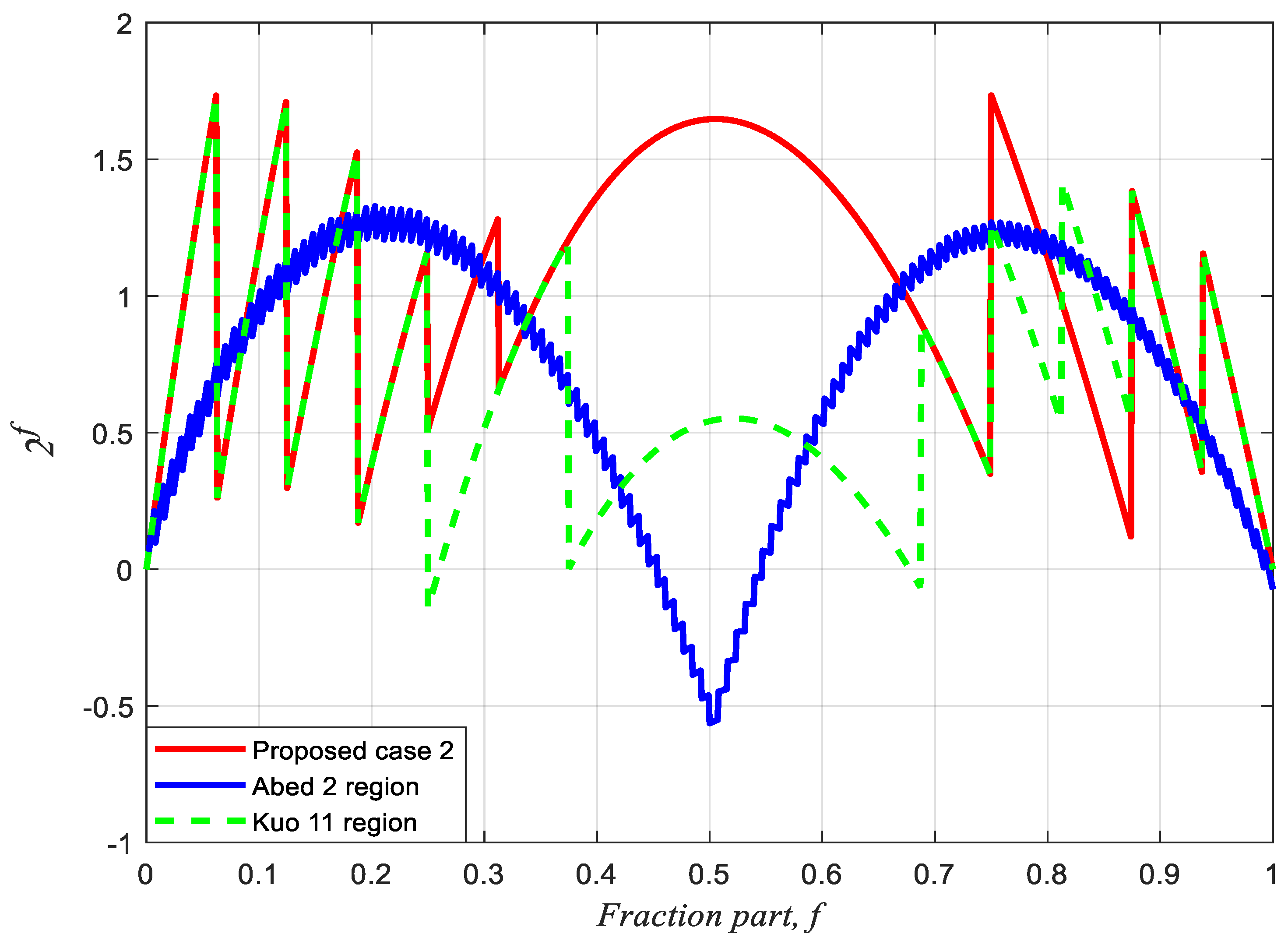
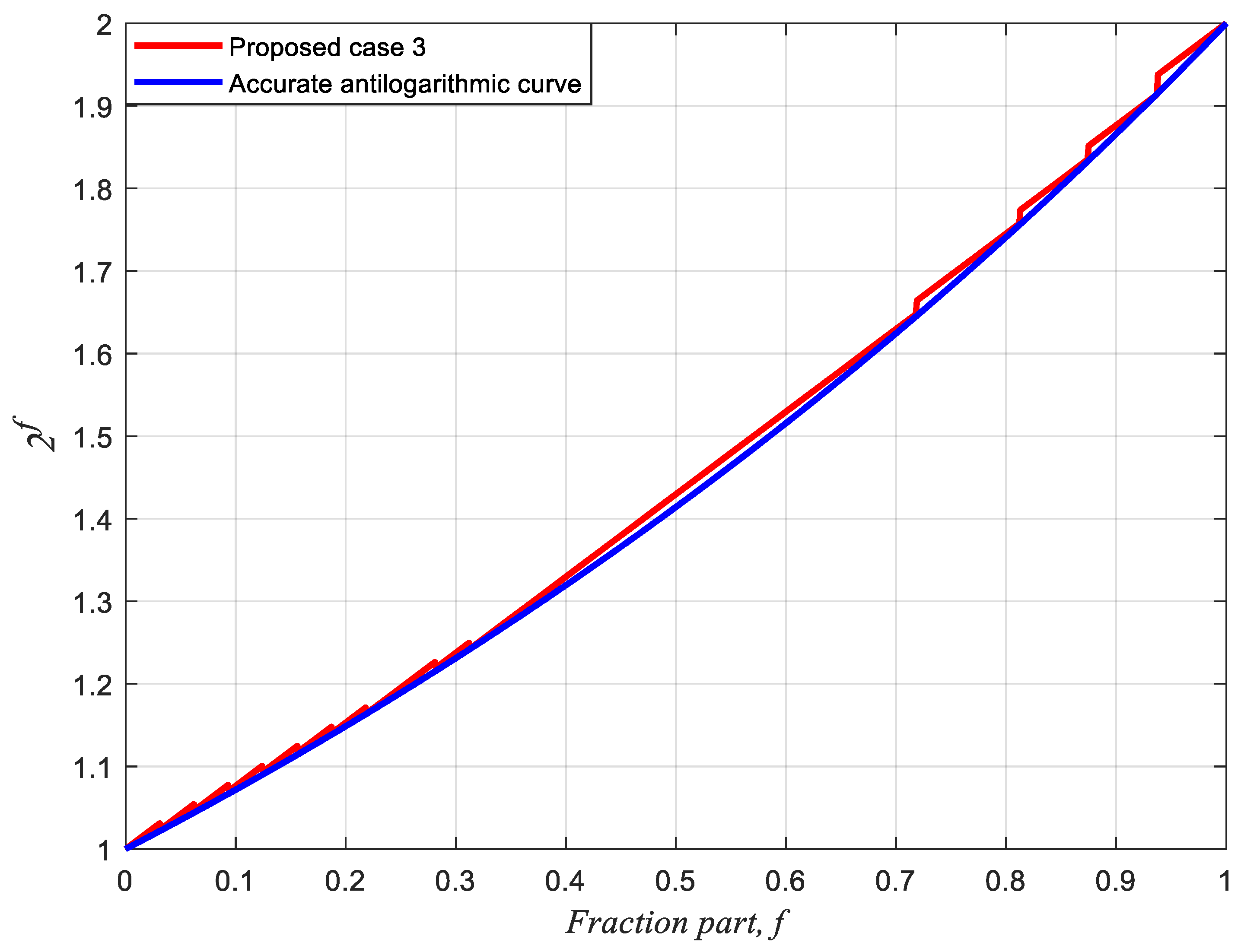
4. Experimental Results and Hardware Implementation

We proposed three equations for eADP-efficient antilogarithmic converters based on fractional-bit compensation schemes under different specifications and requirements for DSP applications. In general, the larger the approximation and maximum percentage error, the less the hardware area cost and delay time. Herein, we first sort the similar maximum percentage errors of antilogarithmic converters reported in the literature as one group and then compare their eADP efficiencies. Next, we compare the performances of the three equations as three groups with those of the methods in the literature. The percentage conversion errors of case 1, case 2, and case 3 are obtained using MATLAB and compared with those of the previous schemes. The maximum percentage conversion errors of case 1, case 2, and case 3 are 1.9089%, 1.7330%, and 1.2063%, respectively. Figure 6 compares case 1 with Juang et al.’s two-region bit correction [13]. Figure 7 compares case 2 with Abed and Siferd’s two-region shift-and-add method [5] and Kuo and Juang’s 11-region constant compensation scheme [16]. Figure 8 compares case 3 with Abed and Siferd’s six-region shift-and-add method [5], Loukrakpam and Choudhury’s two-region shift-and-add method [11], and Kuo’s 14-region constant compensation scheme [16]. Figure 6, Figure 7 and Figure 8 clearly show that the three cases yield considerably lower percentage conversion errors than the previous methods. Figure 9 shows the approximated curve of case 3 compared to the accurate antilogarithmic curve; it is noted that the two-region equation of case 3 is extremely close to the accurate antilogarithmic curve.
Comparisons of the results for VLSI hardware realization and maximum percentage conversion errors for cases 1, 2, and 3 are presented in Table 9, Table 10 and Table 11, respectively. The same hardware and software operation environments are used for all cases and reported methods. For hardware implementation, we used Verilog HDL and had the digital circuits created via VLSI by the Taiwan Semiconductor Manufacturing Company with 0.18 µm CMOS technology. The percentage conversion error is simulated using MATLAB software. In Table 9, Table 10 and Table 11, ADP is defined as the product of hardware area and delay time, while eADP is defined as the product of the approximation’s maximum percentage conversion error, hardware area, and delay time. The approximation’s maximum percentage conversion error is defined as the sum of the absolute value of the positive maximum percentage error and the absolute value of the negative minimum percentage error. Table 9, Table 10 and Table 11 indicate that case 1, case 2, and case 3 can achieve eADP savings of 15.66%, 80.80%, and 84.61% compared with the other methods. The antilogarithmic percentage conversion error, delay time, hardware area, and eADP savings of the proposed cases are superior to those of the other reported methods.
It should be noted that De Morgan’s law of logic circuits can be used to reduce the gate-count number for hardware realization in Equations (10)–(12). Taking f 2 f 3 ¯ f 4 ¯ f 5 ¯ in Equation (12) as an example, f 2 ( f 3 f 4 f 5 ¯ ) can be used to save two gate-counts. Hence, the hardware cost of the proposed eADP-efficient antilogarithmic converters can be significantly reduced by the proposed algorithm of the fractional-bit compensation, Karnaugh map and De Morgan’s law of logic circuits.
The circuit block diagram for hardware implementation for the three cases is shown in Figure 10, where HS is a half subtractor, FS is a full subtractor, fn (where n = 1 to 26) is the uncompensated fractional bit, and fn* (where n = 1 to 26) is the compensated bit. Two regions ( 0 f < 0.5 and 0.5 f < 1 ) of the equations are selected by f−1. The block of logic gates for the compensation circuit (e.g., OR, AND, XOR, and NOT gates) incorporates the combinational logic in the numerators of the equations. In Figure 10, f1/16, f1/32, f1/64, and f1/128 are the compensated output values of 1/16, 1/32, 1/64, and 1/128 in Equations (10)–(12), respectively. For the DSP applications of cases 1, 2, and 3, the more fractional bits there are, the lower the maximum percentage error and approximation error will be. However, more fractional bits will lead to larger hardware area and longer delay time. Therefore, the maximum percentage conversion errors (1.9089%, 1.7330%, and 1.2063%) of cases 1, 2, and 3 can be individually adopted for the error tolerances of specific DSP, digital image processing, or AI applications. We should note that, in this study, the circuit block of Figure 10 is implemented using Verilog HDL code and the digital circuits are integrated by the Taiwan Semiconductor Manufacturing Company with 0.18 µm CMOS technology. MATLAB software is used to display simulation results from Equations (10)–(12) and the other reported methods.

5. Conclusions

We proposed three mathematical equations for antilogarithmic converters with efficient error–area–delay product (eADP) using the fractional-bit compensation scheme. The proposed converters achieved high performance in terms of lower approximation errors, smaller hardware implementation areas, and shorter latency. We compared the proposed algorithms with the previously reported shift-and-add, bit correction, and constant compensation schemes, and found the proposed converters achieved faster result, lower hardware implementation area, and efficient ADP compared to existing methods. The eADP savings of case 1, case 2, and case 3 were 15.66%, 80.80%, and 84.61%, respectively. The digital circuit for the proposed antilogarithmic converters is simple and easy to implement with very-large-scale integration. The proposed eADP-efficient antilogarithmic converters using the fractional-bit compensation scheme are superior to other methods and can be effectively applied to digital signal processing with different specifications and requirements.

Funding

This research received no external funding.

Data Availability Statement

The original contributions presented in the study are included in the article, further inquiries can be directed to the corresponding author.

Acknowledgments

This paper was partly supported by the Ministry of Science and Technology in Taiwan, under grant number MOST 108-2221-E-507-010.

Conflicts of Interest

The author declares no conflicts of interest.

References

  1. Walther, J.S. A Unified Algorithm for Elementary Functions. In Proceedings of the Spring Joint Computer Conference, Atlantic City, NJ, USA, 18–20 May 1971; pp. 379–385. [Google Scholar]
  2. Wong, W.F.; Goto, E. Fast Hardware-Based Algorithms for Elementary Function Computations Using Rectangular Multipliers. IEEE Trans. Comput. 1994, 43, 278–294. [Google Scholar] [CrossRef]
  3. Mitchell, J.N. Computer multiplication and division using binary logarithms. IRE Trans. Electron. Comput. 1962, EC-11, 512–517. [Google Scholar] [CrossRef]
  4. Stine, J.E.; Schulte, M.J. The symmetric table addition method for accurate function approximation. J. VLSI Sig. Proc. 1999, 21, 167–177. [Google Scholar] [CrossRef]
  5. Abed, K.H.; Siferd, R.E. VLSI implementation of a low-power antilogarithmic converter. IEEE Trans. Comput. 2003, 52, 1221–1228. [Google Scholar] [CrossRef]
  6. Juang, T.B.; Chen, S.H.; Cheng, H.J. A lower-error and ROM-free logarithmic converter for digital signal processing applications. IEEE Trans. Circuits Syst. II Express Briefs 2009, 56, 931–935. [Google Scholar]
  7. Nam, B.G.; Kim, H.J.; Yoo, H.J. Power and area-efficient unified computation of vector and elementary functions for handheld 3D graphics system. IEEE Trans. Comput. 2008, 57, 490–504. [Google Scholar] [CrossRef]
  8. Paul, S.; Jayakumar, N.; Khatri, S. A fast hardware approach for approximate, efficient logarithm and antilogarithm computations. IEEE Trans. VLSI Syst. 2009, 17, 269–277. [Google Scholar] [CrossRef]
  9. Liu, C.W.; Ou, S.H.; Chang, K.C.; Lin, T.C.; Chen, S.K. A low-error, cost-efficient design procedure for evaluating logarithms to be used in a logarithmic arithmetic processor. IEEE Trans. Comput. 2016, 65, 1158–1164. [Google Scholar] [CrossRef]
  10. Kuo, C.T. Design and realization of high performance logarithmic converters using non-uniform multi-regions constant adder correction schemes. Microsyst. Technol. 2018, 24, 4237–4245. [Google Scholar] [CrossRef]
  11. Loukrakpam, M.; Choudhury, M. Error-Aware Design Procedure to Implement Hardware-Efficient Antilogarithmic Converters. Circuit Syst. Signal Process. 2019, 38, 4266–4279. [Google Scholar] [CrossRef]
  12. Kuo, C.T. Design and Circuit Implementation of Area-Delay-Product-Efficient Logarithmic Converters Using Mantissa-Bit Compensation Scheme. Circuit Syst. Signal Process. 2022, 41, 4266–4279. [Google Scholar] [CrossRef]
  13. Juang, T.B.; Kuo, H.L.; Jan, K.S. Lower-error and area-efficient antilogarithmic converters with bit correction schemes. J. Chin. Inst. Eng. 2016, 39, 57–63. [Google Scholar] [CrossRef]
  14. Ha, H.; Lee, S. Accurate hardware-efficient logarithm circuit. IEEE Trans. Circuits Syst.—II Express Briefs 2017, 64, 967–971. [Google Scholar] [CrossRef]
  15. Kim, H.; Nam, B.G.; Sohn, J.H.; Woo, J.H.; Yoo, H.J. A 231-MHz, 2.18Mw 32-bit logarithmic arithmetic unit for fixed-point 3-D graphics system. IEEE J Solid State Circuits. 2006, 41, 2373–2381. [Google Scholar] [CrossRef]
  16. Kuo, C.T.; Juang, T.B. Area-efficient and highly accurate antilogarithmic converters with multiple regions of constant compensation schemes. Microsyst. Technol. 2018, 24, 219–225. [Google Scholar] [CrossRef]
  17. Chaudhary, M.; Lee, P. Two-stage logarithmic converter with reduced memory requirements. IET Comput. Digit. Tech. 2014, 8, 23–29. [Google Scholar] [CrossRef]
  18. Chaudhary, M.; Lee, P. An improved two-step binary logarithmic converter for FPGAs. IEEE Trans. Circuits Syst. II Express Briefs 2015, 62, 476–480. [Google Scholar] [CrossRef]
  19. Pineiro, J.A.; Ercegovac, M.D.; Bruguera, J.D. Algorithm and architecture for logarithm, exponential, and powering computation. IEEE Trans. Comput. 2004, 53, 1085–1096. [Google Scholar] [CrossRef]
  20. Gutierrez, R.; Valls, J. Low cost hardware implementation of logarithm approximation. IEEE Trans. Very Large Scale Integr. Syst. 2011, 19, 2326–2330. [Google Scholar] [CrossRef]
  21. Juang, T.B.; Meher, P.K.; Jan, K.S. High-performance logarithmic converters using novel two-region bit-level manipulation schemes. In Proceedings of the 2011 International Symposium on VLSI Design, Automation and Test, Hsinchu, Taiwan, 25–28 April 2011. [Google Scholar]
  22. Caro, D.D.; Petra, N.; Strollo, A.G.M. Efficient logarithmic converters for digital signal processing applications. IEEE Trans. Circuits Syst. II Express Briefs 2011, 58, 667–671. [Google Scholar]
Figure 1. Logarithmic number system.
Applsci 14 01487 g001
Figure 2. The conversion error of Mitchell’s [3] straight-line out = 1 + f and the accurate antilogarithmic curve out = 2f.
Applsci 14 01487 g002
Figure 3. Comparison of Mitchell’s [3] straight-line out = 1 + f and the accurate antilogarithmic curve out = 2f.
Applsci 14 01487 g003
Figure 4. Percentage conversion error of Mitchell’s [3] straight-line out = 1 + f and the accurate antilogarithmic curve out = 2f.
Applsci 14 01487 g004
Figure 5. Flowchart for optimization of eADP in the range 0 ≤ f < 1.0.
Applsci 14 01487 g005
Figure 6. Comparison of the antilogarithmic percentage conversion errors of case 1 and Juang et al.’s [13] 2-region bit correction scheme.
Applsci 14 01487 g006
Figure 7. Comparison of the antilogarithmic percentage conversion errors of case 2 and Abed and Siferd’s [5] 2-region shift-and-add and Kuo and Juang’s [16] 11-region bit constant compensation schemes.
Applsci 14 01487 g007
Figure 8. Comparison of the antilogarithmic percentage conversion errors of case 3 and Abed and Siferd’s [5] 6-region shift-and-add, Loukrakpam and Choudhury’s [11] 2-region shift-and-add, and Kuo and Juang’s [16] 14-region bit constant compensation schemes.
Applsci 14 01487 g008
Figure 9. Approximate curve of proposed case 3 compared to the accurate antilogarithmic curve.
Applsci 14 01487 g009
Figure 10. Circuit block diagram for hardware implementation.
Applsci 14 01487 g010
Table 1. LNS-based operations for arithmetic computations.
Arithmetic ComputationArithmetic OperationLNS-Based Operation
Multiplicationout = a·bA + B
Divisionout = a/bAB
Square root o u t = a A >> 1
Squaringout = a2A << 1
Poweringout = ab A + A + ...... + A b
Reciprocalout = 1/aX
Table 2. Maximum conversion errors and percentage errors for the uncompensated first region and last region.
f−1fnUniform
Partition Numbers
Key Uncompensated
Region
Local
Error
Local
Percentage Error
Absolute
Maximum
Error
Absolute
Maximum
Percentage Error
n = 38First region0.03423.1427%0.04103.1427%
Last region0.04102.2351%
n = 416First region0.01811.7327%0.02211.7327%
Last region0.02211.1551%
n = 532First region0.00930.9083%0.01150.9083%
Last region0.01150.5883%
n = 664First region0.00450.4502%0.00570.4502%
Last region0.00570.2873%
n = 7128First region0.00210.2126%0.00270.2126%
Last region0.00270.1347%
n = 8256First region0.00090.0916%0.00120.0578%
Last region0.00120.0578%
Table 3. Truth table and compensation bits of case 1.
f−1f−4Compensation Bitf−1f−4Compensation Bit
2−42−52−62−72−42−52−62−7
0000000010001000
0001001010011000
0010010010101000
0011011010111000
0100011011000101
0101100011010101
0110100011100010
0111100011110000
Table 4. Partition regions and compensation values of case 1.
Partition
Items
Partition RegionCompensation
Value
Partition
Items
Partition
Region
Compensation
Value
1[0, 1/16)05[5/16, 12/16)−8/128
2[1/16, 2/16)−2/1286[12/16, 14/16)−5/128
3[2/16, 3/16)−4/1287[14/16, 15/16)−2/128
4[3/16, 5/16)−6/1288[15/16, 1)0
Table 5. Truth table and compensation bits of case 2.
f−1f−4Compensation Bitf−1f−4Compensation Bit
2−42−52−62−72−42−52−62−7
0000000010001000
0001001010011000
0010010010101000
0011011010111000
0100011111000101
0101100011010101
0110100011100010
0111100011110000
Table 6. Partition regions and compensation values of case 2.
Partition
Items
Partition RegionCompensation
Value
Partition
Items
Partition
Region
Compensation
Value
1
2
3
4
5
[0, 1/16)
[1/16, 2/16)
[2/16, 3/16)
[3/16, 4/16)
[4/16, 5/16)
0
−2/128
−4/128
−6/128
−7/128
6
7
8
9
[5/16, 12/16)
[12/16, 14/16)
[14/16, 15/16)
[15/16, 1)
−8/128
−5/128
−2/128
0
Table 7. Truth table and compensation bits of case 3.
f−1f−5Compensation Bitf−1f−5Compensation Bit
2−42−52−62−72−42−52−62−7
000000000100001001
000010001100011001
000100010100101001
000110011100111001
001000100101001001
001010101101011001
001100110101101001
001110111101110111
010000111110000111
010011000110010111
010101001110100101
010111001110110101
011001001111000011
011011001111010011
011101001111100000
011111001111110000
Table 8. Partition regions and compensation values of case 3.
Partition
Items
Partition RegionCompensation
Value
Partition
Items
Partition
Region
Compensation
Value
1[0, 1/32)08[7/32, 9/32)−7/128
2[1/32, 2/32)−1/1289[9/32, 10/32)−8/128
3[2/32, 3/32)−2/12810[10/32, 23/32)−9/128
4[3/32, 4/32)−3/12811[23/32, 26/32)−7/128
5[4/32, 5/32)−4/12812[26/32, 28/32)−5/128
6[5/32, 6/32)−5/12813[28/32, 30/32)−3/128
7[6/32, 7/32)−6/12814[30/32, 1)0
Table 9. Comparison of percentage conversion errors and results for proposed case 1 and Juang et al.’s [13] two-region bit correction schemes.
Compared ItemsJuang et al. [13]Proposed
Case 1
Compensation schemeBitFractional bits
Segment number22
Significant fractional bitnonenone
Max. positive percentage error1.72%1.9089%
Min. negative percentage error−0.6%0
Total percentage conversion error2.32%1.9089%
Area (µm2)1729.621772.97
Delay (ns)0.70.7
ADP1210.7341241.079
ADP saving0−2.51%
eADP28.089023.6910
eADP saving015.66%
Table 10. Comparison of percentage conversion errors and results for proposed case 2 and Abed and Siferd’s [5] two-region and Kuo and Juang’s [16] 11-region schemes.
Compared ItemsAbed & Siferd [5,16]Kuo & Juang [16]Proposed
Case 2
Compensation schemeShift-and-AddConstantFractional bits
Segment number2112
Significant fractional bit7nonenone
Max. positive percentage error1.3310%1.7327%1.7330%
Min. negative percentage error−0.5631%−0.0992%0
Total percentage conversion error1.8941%1.8319%1.7330%
Area (µm2)3562.572807.481869.44
Delay (ns)21.40.8
ADP7125.143930.471495.55
ADP saving044.84%79.01%
eADP134.957371.259425.9179
eADP saving047.20%80.80%
Table 11. Comparison of percentage conversion errors and results for proposed case 3 and Abed and Siferd’s [5] six-region, Kuo and Juang’s [16] 14-region, and Loukrakpam and Choudhury’s [11] two-region schemes.
Compared ItemsAbed & Siferd
[5,16]
Kuo & Juang
[16]
Loukrakpam
[11]
Proposed
Case 3
Compensation schemeShift-and-AddConstantShift-and-AddFractional bits
Segment number61422
Significant fractional bit7none7none
Max. positive percentage error0.9572%1.2%1.5054%1.1551%
Min. negative percentage error−0.5786%−0.1436%−0.0488%−0.0512%
Total percentage conversion error1.5358%−0.1436%1.5542%1.2063%
Area (µm2)6439.913319.755425.362122.24
Delay (ns)6439.911.51.81.1
ADP11,913.834979.639765.652334.46
ADP saving058.20%18.31%80.41%
eADP182.972666.9063151.7828.1606
eADP saving063.43%17.05%84.61%
Disclaimer/Publisher’s Note: The statements, opinions and data contained in all publications are solely those of the individual author(s) and contributor(s) and not of MDPI and/or the editor(s). MDPI and/or the editor(s) disclaim responsibility for any injury to people or property resulting from any ideas, methods, instructions or products referred to in the content.

