
Investigation into the Uniformization of Proton Beams for FLASH Therapy

1
Faculty of Material Science and Technology, Shanghai-Tech University of China, Shanghai 200127, China
2
Shanghai Institute of Applied Physics, Chinese Academy of Sciences, Shanghai 201899, China
3
Shanghai Key Laboratory of Proton-Therapy, Shanghai 201801, China
*
Author to whom correspondence should be addressed.
Appl. Sci. 2024, 14(6), 2660; https://doi.org/10.3390/app14062660
Submission received: 4 February 2024
/
Revised: 7 March 2024
/
Accepted: 14 March 2024
/
Published: 21 March 2024
(This article belongs to the Section Applied Physics General)
Abstract
:Featured Application
A beam-expanding method that can achieve uniform proton beams for FLASH therapy is provided.
Abstract
FLASH proton therapy is widely considered in many labs. However, achieving a dose rate sufficient for FLASH is challenging, especially when using the scanning method. A beam uniformization process using a nonlinear magnet is employed to reduce the scanning time, supplemented by multi-energy extraction to enhance the dose rate. The impact of octupole fields, multipole field components, and step field on the transport line are tested. The nonlinear effect of the magnetic fields on the transverse motion of the particle beam is used to establish a uniform dose distribution at the target. Different schemes are investigated and the octupole approach was finally selected.
1. Introduction
As one of the modern ways to treat cancer, radiation therapy is the cornerstone of curative and palliative cancer treatment [1]. Modern research indicates that ultra-high-dose-rate (>40 Gy/s) irradiation [1,2] leads to a significantly higher survival rate of normal cells than low dose rates [3], making it clinically advantageous for reducing the side effects of radiation therapy. This phenomenon reduces radiation-induced toxicity while maintaining an equivalent tumor response. Therefore, to ensure experimental integrity, for example, to compare the performance of two medical devices used on the neck, radiation therapy was used to establish a control group in clinical trials [4]. In order to realize the clinical FLASH effect, high requirements were put forward in terms of the current-extraction strength of the accelerator, the beam-conveying hardware and scanning control system, the scanning mode of the proton beam, and the utilization of the beam after scanning [5,6]. Since 2014, FLASH therapy has made significant advancements in various in vivo studies [7,8,9]. Achieving FLASH therapy has become a focal point in the development of equipment. Ultra-high dose rates impose stringent requirements on beam modulation, especially for proton therapy. The “bragg peak” effect leads to better dose distribution of protons in normal tissue. When proton therapy is used in patients with head and neck cancer, it minimizes the dose of radiation to important structures around the tumor, thus reducing toxicity and improving the prognosis of patients with head and neck cancer [10]. However, more beam modulation is required to conform to the target. Energy changes and beam spot scanning are employed in longitudinal and transverse directions, respectively. Due to the small initial size of the beam extracted from accelerators, typical point-scanning treatments for three-dimensional tumor conformation are time-consuming. Double scattering treatments have a low beam transmission efficiency, necessitating higher beam-intensity requirements for accelerators. Several methods, such as shoot-through, 3D modulators, layer stacking, and scanning by deflecting cavities, are under development [11].
Proton therapy based on the use of an synchrotron accelerator adopts a third-order resonance, slow extraction method [12], making it challenging to meet the FLASH dose rate requirements [1]. In this paper, beam expansion with uniformization is considered an effective approach. To achieve beam expansion through uniformization, the utilization of higher-order or specially shaped magnetic fields is needed to modulate beam shape and density [13,14]. Leveraging the domestically produced proton therapy system, the research focuses on beam uniformization in the transport line, experimenting with different types of magnets to expand and homogenize the initially Gaussian-distributed beam. This progress forms a uniform distribution in a single energy slice and reaches the required dose within a short time according to the different beam currents. No scanning time is required. By incorporating multi-energy extraction to enhance the dose rate, the goal of FLASH therapy can be achieved. Additionally, the integration of a rapid-cycling synchrotron accelerator [15] can offer more advanced modulation methods and a higher particle number in the same time scale, reducing the impact of radiation on the environment, lowering the accelerator performance requirements, and enabling the clinical translation of FLASH therapy.
Unlike the other beam modulation devices, which are mainly located in the nozzle, the higher-order or specially shaped magnet often sits in the transport line and should be designed together with the transport line. This scheme of homogenizing nonlinear magnet elements to ensure uniformization in the transport line is called beam-broadening homogenization, for which the use of a multipole magnet for beam spot homogenization was first proposed by Meads [16]. Kashy and Sherrill verified the homogenization effect of the octupole magnet via numerical calculation for a specific optical path [17]. Later, they demonstrated that the homogenization of Gaussian beam spots requires odd-order multipolar fields, such as octupole magnets and dodecapole magnets [18]. Jing-yu Tang proposed a step-like field magnet (SFM) and studied its uniformization effect [19]. Both domestically and internationally, schemes for beam transport uniformization include nonlinear magnets with two pairs of octupole magnets and twelve-pole magnets in the ESS long-pulse target transport line [20], and two pairs of octupole nonlinear magnets in the CLAPA-II laser accelerator at Peking University [21]. A step-like magnet was designed for the IFIF-HEBT transport lines [20]. A comparison is made among different non-linear magnets and combinations to determine the optimal uniformization method.
2. Materials and Methods
2.1. The Physical Principle of Beam Uniformization Using Nonlinear Magnets
A pair of octupole fields, a pair of octupole and dodecapole pole fields, and a pair of step fields were inserted into transport lines, and their effects on the uniformity of the beam spot at the target (selected at the end of the transport line) were compared.
2.1.1. Multipole Magnet
According to the Taylor expansion of Cartesian coordinates, the expansion of the magnetic field in the x and y directions is expressed as follows:
where and represent the coefficients of the 2nth polar field. n is the number of axes of symmetry, is the positive multipole field, and is the oblique multipole field. and represent the reference magnetic field and the corresponding reference orbit. Therefore, each term of the x and y expansions above represents the formula for the magnetic field strength of the 2n pole, respectively. When n = 4 and n = 6, the magnetic field formula of the normalized positive octupole-pole field and dodecapole-pole field is [21,22] listed in Table 1:
In the formula, G and M represent the focusing constant of the multipole magnet, indicating the strength of the magnet’s focusing capability.
The initial proton beam density distribution at the multipole magnet follows the Gaussian distribution formula:
where σ0 represents the RMS radius of the beam envelope and x0 represents the particle coordinates. The formula for the uniformized density at the target is given by , where is the beam spot width.
The density formula at the target under the function of a multipole magnet is [23]:
where represents the focusing constant of the multipole magnet and φ is the phase advance between the multipole magnet and the target. are the beta function at the multipole magnet and the target. Substituting these into Equation (4) can obtain [23]:
Through analysis, it was determined that for n = 4, 6, 8, …, corresponding to odd-order nonlinear terms in the respective magnets, a uniformized beam distribution can be achieved. According to formula (5), the beam spot width is unrelated to the strength of the nonlinear magnet but depends on the phase advance in other linear elements during propagation and the amplitude function at the target. To achieve uniformization, the strength of the multipole nonlinear magnet used is inversely proportional to the β function before entering the multipole magnet.
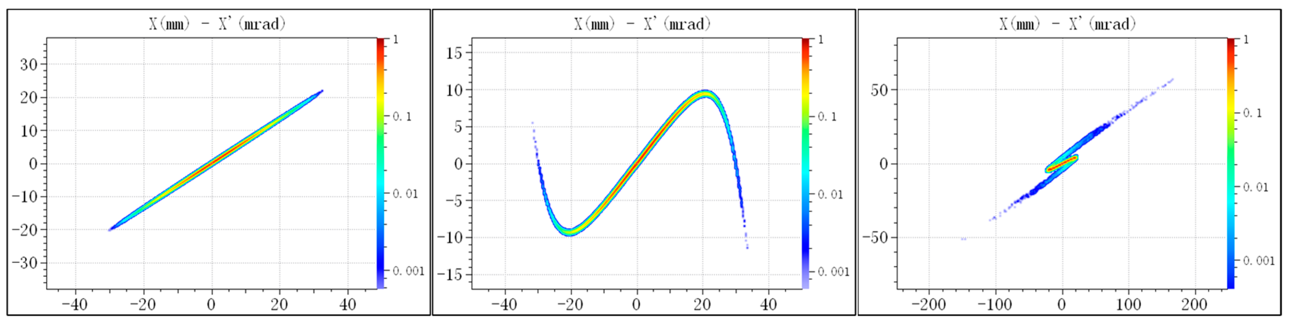
The primary principle of uniformization using a nonlinear magnet is shown in Figure 1. First, the two bow sections with low particle density in the normalized phase diagram were translated up and down by a small phase difference, and then the bow section was rotated through the drift space or the lateral phase shift of the focusing element, so that the projection of its x coordinate was overlapped within the uncut part, thus achieving beam uniformization.
To achieve uniformization in both the x and y directions, at least two pairs of nonlinear magnetic fields are required to act separately in each direction. To minimize coupling effects, it is essential to “flatten” the beam before the nonlinear magnets. The resulting beam envelope, when inserting a nonlinear magnet into this transport line segment, is depicted in Figure 4 (1). The magnetic field gradient of the two pairs of octupole magnets is 2978 T/m3 to −1910 T/m3, while the gradients for the octupole and dodecapole magnet components are 2978 T/m3 to −150,000 T/m5 and −1910 T/m3 to −1,370,000 T/m5, respectively.
From Figure 2, it is evident that the dodecapole component can eliminate the “peak” effect caused by the octupole magnet, resulting in a flatter beam and an increased uniform region. This is attributed to the addition of higher-order magnetic field components, which increase the steepness of the beam spot, compensating for the effects produced by the lower-order components. Figure 3 is the cross-section view of multipole magnet.
2.1.2. Step-like Magnet
The principle of a step-like magnet is similar to that of a multipole magnet, and they can both be called nonlinear magnets. From the images generated in Figure 4 for the step-like field and the field produced by multiple poles, it is evident that their magnetic fields are significantly higher at the transverse edges, generating a field much larger than the central field uniformization.
The fitting curve in the other direction can be approximated by calculation as:
The magnetic field strength of the step field, denoted as B0, is defined as B0 = Fs/L, where Fs represents the step field strength, L is the step width, b represents the step steepness, and x0 denotes the position of the step’s rise or fall [19]. Figure 4 shows the difference between the magnetic field map of the step-like field and octupole field.
Referring to Formula (5), with certain adjustments, the density between the peaks is enhanced, while the peaks at the edges of the beam spot are diminished. The design parameters of the two pairs of step-like magnets are shown in Table 2 [20,25]:
The schematic figure of the step-like magnet designed by OPERA 2021 modeling software is shown in the Figure 5; a step-like magnetic field can be achieved by a magnet with a nested structure of two pairs of yokes and two pairs of coils. The flat-top field is used to fold transverse particles at the magnet into the beam core at the target. The outer yoke and coil are also called the main core and main coil, while the inner yoke and coil are called the auxiliary core and coil.
3. The Physical Principle of Beam Uniformization Using Nonlinear Magnet
The main function of the transport line shown in Figure 6 is to adjust the envelope and spot size of the proton beam, match the transverse and longitudinal phase spaces, and deliver the beam to the corresponding treatment room [26]. The extraction proton beam from a medical synchrotron has an energy range between 70 MeV and 235 MeV, with an emittance ranging from 1 to 10 π·mm·mrad [26]. The divergence angle, energy spread, and beam radius are crucial factors in determining the characteristics and behavior of the beam as it progresses through the transport line and interacts with the treatment room components. The specified number of particles indicates the scale at which the simulation or modeling is conducted, allowing for a detailed analysis of the proton beam dynamics.
The transport line is primarily composed of two dipole magnets with a bending angle of 30° and a curvature radius of 1500 mm, offset sections, collimators, and ten quadrupole magnets. Figure 4b shows the envelope figure of the beam. is the RMS radius of the beam envelope. According to the formula , the envelope of the beam is related to the emittance of the initial particle distribution and the linear element in the optical path. Table 3 lists the design parameters for the dipole and quadrupole magnets, where the magnetic field gradient represents the setting parameters of the quadrupole magnet and the radius curvature of the central trajectory represents the dipole magnet. M1 and M2 in Figure 6 represent the insertion positions of two pairs of nonlinear magnets.
Among them, DIP represents a dipole magnet; according to the design needs, the curvature of the two bipolar irons is 1500 mm and the bending angle is 30°. QP stands for quadrupole magnet. The radius, length, and magnetic field gradient of the quadrupole magnet and the length of drifts are mainly determined by the size of the envelope when the beam passes through the first and second nonlinear magnets and the β value of the horizontal and vertical amplitude functions; the modulation parameters were realized using TRANSPORT 1998 software [27].
As shown in Figure 7, the data input into the transport software mainly consists of the design parameters of the initial particle bundle (including the design of TWISS parameters) and the LATTICE structure design parameters of each element (including the length of the element L, focusing constant K1). The TWISS parameters at the nonlinear magnets are modified using the “FIT” command, and the modified results were imported into the TraceWin 2021 [28] beam dynamics software to convert the corresponding gradient value (G), and the aperture size (R) in the corresponding LATTICE was modified according to the envelope size, and the optimal solution are obtained through repeated optimization.
When the particle beam passes through the aforementioned nonlinear magnets, the action of nonlinear forces results in the distortion of the external region while leaving the transverse spatial region unaffected [28]. Consequently, the beam envelope trajectory of the beam remains unchanged. The phase space distortion at the nonlinear magnet induces rotation in the subsequent matrix transport process, effectively moving edge particles towards the center of the beam. Notably, for optimal beam uniformization, specific designs are required for the placement of nonlinear magnets. These designs can be categorized into two aspects: horizontal and vertical requirements. Firstly, to minimize beam coupling in the horizontal and vertical directions, the beam cross-section at the nonlinear magnet should be “flattened”. This means that the horizontal size-to-vertical size ratio of the beam should be greater than 4 [21]. This ensures that coupling effects between the two directions do not adversely affect uniformization. The mentioned transverse size ratio refers to the ratio of the maximum beam width in the x-direction to that in the y-direction. At the first nonlinear magnet, this ratio is defined as the maximum value in the x-direction divided by the maximum value in the y-direction. At the second nonlinear magnet, it is defined as the maximum value in the y-direction divided by the maximum value in the x-direction. Secondly, the position of the nonlinear magnet should have a phase shift with the target position as close to π or 2π as possible. This is necessary to achieve specific rotation angles in phase space, allowing distorted edge particles to overlay in the central region of the beam, thereby improving the uniformity of particle distribution [23]. The action of the quadrupole magnet before the first nonlinear magnet is to adjust the ratio of the β functions in the x and y directions, making the βx value larger and the βy value smaller. This ensures a suitable ratio at the nonlinear magnet, as shown in Figure 8, with the ratio at the first nonlinear magnet in the case being βx/βy = 66/3. Similarly, after passing through the first nonlinear magnet, the beam undergoes magnetic focusing through the FODO structure [29], increasing the βy value and decreasing the βx value. In this case, the ratio at the second nonlinear magnet is βy/βx = 70/0.12. Due to a significant increase in the horizontal Ɛrms after the first nonlinear magnet, lowering the βx value is necessary to match the transverse size ratio of the beam at the second nonlinear magnet.
After passing through the second nonlinear magnet, the beam undergoes vertical compression and horizontal expansion using three quadrupole magnets. This process ensures that, at the exit of the final quadrupole magnet, the horizontal and vertical beta functions are maintained, and Ɛrms remains consistent. Subsequently, a long drift section is employed to enlarge the beam spot. According to Formula (5), the width of the beam spot, denoted as 2rₜ, is dependent on the beta functions at the target location. Therefore, the length of the drift section can be adjusted to alter the size of the beam spot.
In order to compare the uniformity at the target when different nonlinear magnet elements are inserted, two pairs of nonlinear magnets were inserted at the same position (m1 and m2), and the cross-section of the particles was intercepted in the same range.
4. Comparison of Uniformization Results
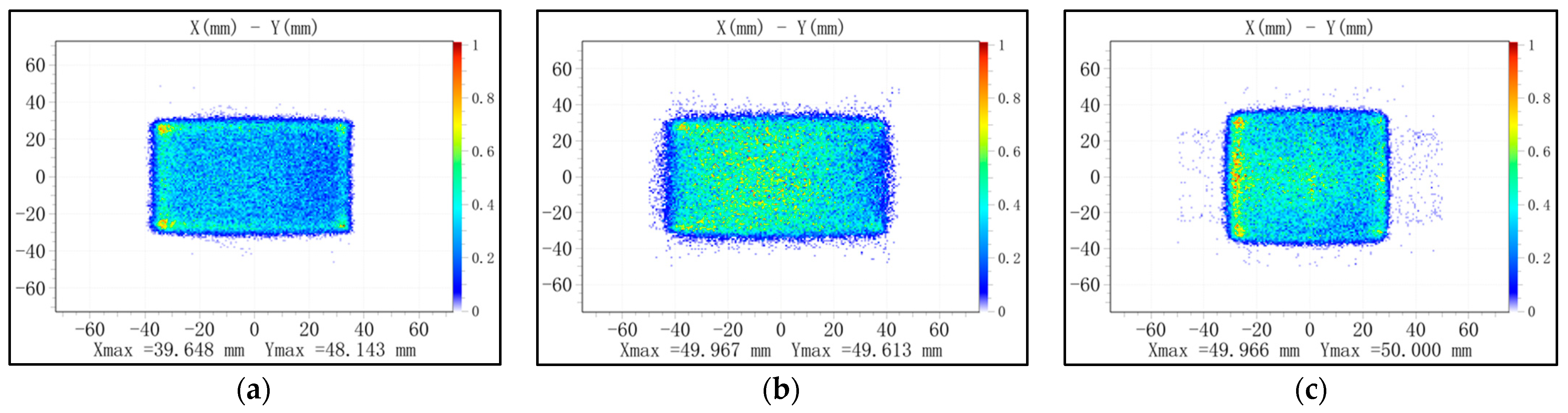
Without altering the central trajectory of the beam in the aforementioned transport line, particle cross-sections at the target were selectively intercepted using a collimator with a radius of 50 mm. The resulting beam spot cross-sections are shown in Figure 9, with particle loss rates of 0.004%, 0.02%, and 1.4%, respectively. Overall, the results indicate that the use of nonlinear magnets in the design of the proton therapy device’s transport line significantly enhances beam uniformity, yielding positive effects for various applications. To assess the uniformity of the beam spot, in Figure 10, a 20 × 20 grid was applied to a cross-sectional area of 100 mm × 100 mm, totaling 400 individual grids with each grid measuring 5 mm × 5 mm. Particle counts within each corresponding grid were then recorded and analyzed.
From left to right, the figures correspond to the selection of horizontal and vertical grids from the 5th to the 16th. Specifically, the middle picture selects horizontal grids ranging from the 5th to the 16th and the vertical grids range from the 3rd to the 17th. The horizontal grids span from the 4th to the 17th and the vertical grids range from the 6th to the 16th. The utilization rates for particles are 78.78%, 84.38%, and 82.5%, respectively. The coordinates of each grid are determined by the indices , where and represent the horizontal and vertical directions, and the particle count in each grid is denoted as , . The formula for calculating non-uniformity is defined as [30]:
Through calculations, the obtained results for non-uniformity are ±10.09%, ±13.23%, and ±12.3% for the methods using octupole magnet, multipole magnet components, and step-like field. The comparison results are shown in Table 4. The results indicate that the method of using multipole magnet components achieves the highest beam utilization, while the method using only the octupole magnet yields the best non-uniformity result, but the difference is very small. Considering the need for flatness in clinical settings to achieve the FLASH treatment effect, the design with the octupole magnet-only approach is deemed more optimal.
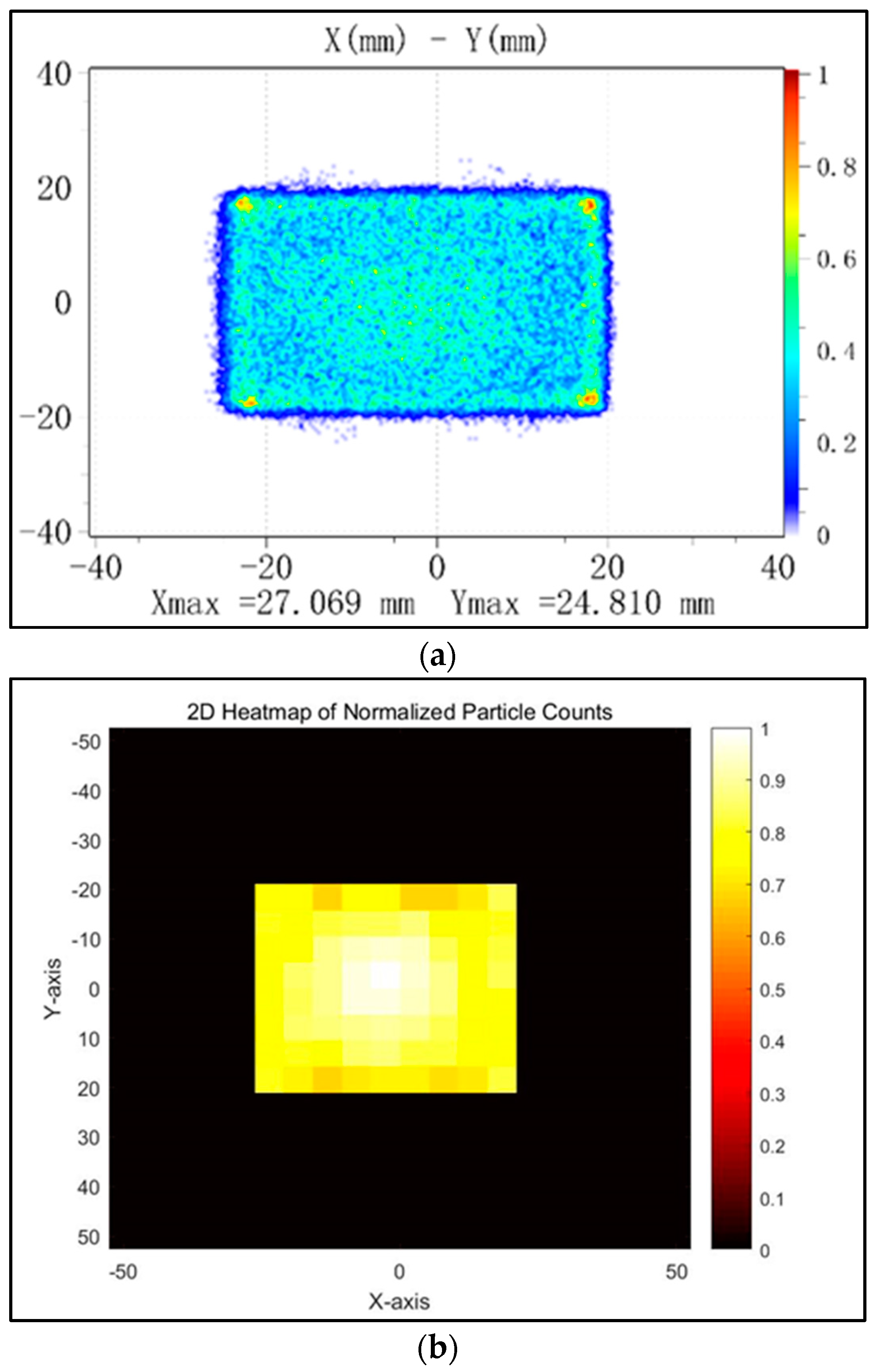
Due to the impact of beam energy dispersion, the beam spot cross-section generated by the octupole magnet exhibits an asymmetric distribution, to reduce the non-uniformity of the beam spot, enhance beam uniformization, and improve the flatness and symmetry of the beam scanned in the horizontal direction, a sext-pole magnet with the same size gradient of −8.62/m2 is added after the first octupole magnet in the horizontal direction. Additionally, the gradient component of the second octupole magnet is optimized and reduced to −1199/m3. The results at the target location are shown in Figure 11, the same area as the grid drawn above, with a 20 × 20 grid applied to a cross-sectional area of 100 mm × 100 mm, totaling 400 individual grids with each grid measuring 5 mm × 5 mm. Selecting i values from the 7th to the 14th grid and j values from the 6th to the 14th grid, the particle utilization rate is 99.23%. The calculated non-uniformity result is ±7.5%, the utilization rate of the particles is improved, and the heterogeneity is reduced, which may enable the clinical transformation of the FLASH effect [31].
5. Conclusions
This study focuses on the design of a transport line for the proton beam extracted from a synchrotron accelerator in a domestic proton therapy device. The designed transport line is 9.6 m long. Three different types of nonlinear magnets (octupole magnet, a combination of octupole and dodecapole magnets (multipole magnet components), step-like magnet) were inserted at the locations corresponding to the horizontal and vertical “flat beam” of the beam cross-section. By comparing the unevenness of the cross-sectional distribution at the target, it was concluded that using octupole magnets maximizes the uniformity of the beam. To reduce the impact of energy dispersion on the beam uniformity, a sext-pole magnet was added after the first octupole magnet, improving both the beam uniformity and utilization efficiency. This may enable increasing the dose rate and achieving the clinical translation of the FLASH effect. However, the disadvantage is that the design of the above-mentioned transport lines is relatively simplified, lacking complete simulation, and subsequent experimental verification is needed. In addition, considering the limitations of radiation therapy in the treatment of tumors, other effective schemes should be considered in the actual treatment [32].
Author Contributions
Conceptualization, M.Z.; methodology, M.Z.; software, M.Z.; validation, M.Z.; formal analysis, X.H. and M.Z.; investigation, X.H. and M.Z.; resources, X.H.; data curation, X.H.; writing—original draft preparation, X.H.; writing—review and editing, M.Z.; visualization, M.Z.; supervision, M.Z.; project administration, M.Z.; funding acquisition, M.Z. All authors have read and agreed to the published version of the manuscript.
Funding
This research received no external funding.
Institutional Review Board Statement
Not applicable.
Informed Consent Statement
Not applicable.
Data Availability Statement
The raw data supporting the conclusions of this article will be made available by the authors on request.
Acknowledgments
The authors would like to thank colleagues Hua-Fei Yu of the School of Communication and Information Engineering, Shanghai University, for their help with the article. The authors would also like to thank the anonymous reviewers for their constructive comments.
Conflicts of Interest
The authors declare no conflicts of interest.
References
- Wilson, J.D.; Hammond, E.M.; Higgins, G.S.; Petersson, K. Ultra-High Dose Rate (FLASH) Radiotherapy: Silver Bullet or Fool’s Gold? Front. Oncol. 2020, 9, 1563. [Google Scholar] [CrossRef]
- Esplen, N.M.; Mendonca, M.S.; Bazalova-Carter, M. Physics and biology of ultrahigh dose-rate (FLASH) radiotherapy: A topical review. Phys. Med. Biol. 2020, 65, 23TR03. [Google Scholar] [CrossRef]
- Bourhis, J.; Sozzi, W.J.; Jorge, P.G.; Gaide, O.; Bailat, C.; Duclos, F.; Patin, D.; Ozsahin, M.; Bochud, F.; Germond, J.-F.; et al. Treatment of a first patient with FLASH-radiotherapy. Radiother. Oncol. 2019, 139, 18–22. [Google Scholar] [CrossRef] [PubMed]
- Serra, A.; Spinato, G.; Spinato, R.; Conti, A.; Licciardello, L.; Di Luca, M.; Campione, G.; Tonoli, G.; Politi, D.; Castro, V.; et al. Multicenter prospective crossover study on new prosthetic opportunities in post-laryngectomy voice rehabilitation. J. Biol. Regul. Homeost. Agents 2017, 31, 803. [Google Scholar]
- Zou, W.; Diffenderfer, E.S.; Cengel, K.A.; Kim, M.M.; Avery, S.; Konzer, J.; Cai, Y.; Boisseu, P.; Ota, K.; Yin, L.; et al. Current delivery limitations of proton PBS for FLASH. Radiother. Oncol. 2021, 155, 212–218. [Google Scholar] [CrossRef] [PubMed]
- Zhang, G.L.; Wang, J.L. Proton FLASH: Passive scattering or pencil beam. Phys. Med. Biol. 2021, 66, 03NT01. [Google Scholar] [CrossRef] [PubMed]
- Favaudon, V.; Caplier, L.; Monceau, V.; Pouzoulet, F.; Sayarath, M.; Fouillade, C.; Poupon, M.-F.; Brito, I.; Hupé, P.; Bourhis, J.; et al. Ultrahigh dose-rate FLASH irradiation increases the differential response between normal and tumor tissue in mice. Sci. Transl. Med. 2014, 6, 245ra93. [Google Scholar] [CrossRef] [PubMed]
- Girdhani, S.; Abel, E.; Katsis, A.; Rodriquez, A.; Senapati, S.; KuVillanueva, A.; Jackson, I.L.; Eley, J.; Vujaskovic, Z.; Parry, R. Abstract LB-280: FLASH: A novel paradigm changing tumor irradiation platform that enhances therapeutic ratio by reducing normal tissue toxicity and activating immune pathways. In Proceedings of the AACR Annual Meeting 2019, Atlanta, GA, USA, 29 March–3 April 2019. [Google Scholar]
- Montay-Gruel, P.; Acharya, M.M.; Petersson, K.; Alikhani, L.; Yakkala, C.; Allen, B.D.; Ollivier, J.; Petit, B.; Jorge, P.G.; Syage, A.R.; et al. Long-term neurocognitive benefits of FLASH radiotherapy driven by reduced reactive oxygen species. Proc. Natl. Acad. Sci. USA 2020, 116, 10943–10951. [Google Scholar] [CrossRef] [PubMed]
- Nuyts, S.; Bollen, H.; Ng, S.P.; Corry, J.; Eisbruch, A.; Mendenhall, W.M.; Smee, R.; Strojan, P.; Ng, W.T.; Ferlito, A. Proton Therapy for Squamous Cell Carcinoma of the Head and Neck: Early Clinical Experience and Current Challenges. Cancers 2022, 14, 2587. [Google Scholar] [CrossRef] [PubMed]
- Kumada, H. Beam Delivery System for Proton Radiotherapy. In Proton Beam Radiotherapy: Physics and Biology; Tsuboi, K., Sakae, T., Gerelchuluun, A., Eds.; Springer: Singapore, 2020; pp. 97–112. [Google Scholar]
- Pullia, M.G. Synchrotrons for Hadrontherapy. Rev. Accel. Sci. Technol. 2009, 2, 157–178. [Google Scholar] [CrossRef]
- Guo, Z.; Tang, J.Y.; Yang, Z.; Wang, X.Q.; Sun, B. A novel structure of multipole field magnets and their applications in uniformizing beam spot at target. Nucl. Instrum. Methods Phys. Res. Sect. A Accel. Spectrometers Detect. Assoc. Equip. 2012, 691, 97–108. [Google Scholar] [CrossRef]
- Meot, F.; Aniel, T. Principles of the non-linear tuning of beam expanders. Nucl. Instrum. Methods Phys. Res. Sect. A Accel. Spectrometers Detect. Assoc. Equip. 1996, 379, 196–205. [Google Scholar] [CrossRef]
- Nagaitsev, S.; Lebedev, V. A Cost-Effective Rapid-Cycling Synchrotron. Rev. Accel. Sci. Technol. 2019, 10, 245–266. [Google Scholar] [CrossRef]
- Meads, P.F., Jr. A Nonlinear Lens System to Smooth the Intensity Distribution of a Gaussian Beam. IEEE Trans. Nucl. Sci. 2007, 30, 2838–2840. [Google Scholar] [CrossRef]
- Kashy, E.; Sherrill, B. A method for the uniform charged particle irradiation of large targets. Nucl. Instrum. Methods Phys. Res. Sect. B Beam Interact. Mater. At. 1987, 26, 610–613. [Google Scholar] [CrossRef]
- Sherrill, B.; Bailey, J.; Kashy, E.; Leakeas, C. Use of multipole magnetic fields for making uniform irradiations. Nucl. Instrum. Methods Phys. Res. 1989, 40 Pt 2, 1004–1007. [Google Scholar] [CrossRef]
- Tang, J.Y.; Li, H.H.; An, S.Z.; Maier, R. Distribution transformation by using step-like nonlinear magnets. Nucl. Instrum. Methods Phys. Res. Sect. A 2004, 532, 538–547. [Google Scholar] [CrossRef]
- Yang, Z.; Tang, J.Y. Using Step-Like Nonlinear Magnets for Beam Uniformization at IFMIF Target. In Proceedings of the HB2012, Beijing, China, 17–21 September 2012. [Google Scholar]
- Wang, K.; Zhu, K.; Easton, M.J.; Li, Y.; Xie, X.; Lan, H.; Cai, S.; Wang, H.; Ge, H.; Zhu, T.; et al. Beam distribution homogenization design for laser-driven proton therapy accelerator. Nucl. Instrum. Methods Phys. Res. Sect. A Accel. Spectrometers Detect. Assoc. Equip. 2022, 1040, 167196. [Google Scholar] [CrossRef]
- Tanabe, J.T. Iron Dominated Electromagnets: Design, Fabrication, Assembly and Measurements; World Scientific: Singapore, 2005. [Google Scholar]
- Yuri, Y.; Miyawaki, N.; Kamiya, T.; Yokota, W.; Arakawa, K.; Fukuda, M. Uniformization of the transverse beam profile by means of nonlinear focusing method. Phys. Rev. Accel. Beams 2007, 10, 104001. [Google Scholar] [CrossRef]
- Tang, J.Y.; Wei, G.H.; Zhang, C. Step-like field magnets to transform beam distribution at the CSNS target. Nucl. Instrum. Methods Phys. Res. 2007, 582, 326–335. [Google Scholar] [CrossRef]
- Tang, J.Y.; Feng, G.Y.; Liu, G.W. Design and Prototyping of a Step-Like Field Magnet. IEEE Trans. Appl. Supercond. 2010, 20, 1041–1044. [Google Scholar] [CrossRef]
- Furukawa, T.; Noda, K.; Fujimoto, T.; Uesugi, T.; Shibuya, S.; Torikoshi, M. Optical matching of a slowly extracted beam with transport line. Nucl. Instrum. Methods Phys. Res. 2006, 560, 191–196. [Google Scholar] [CrossRef]
- Carey, D.C.; Brown, K.L.; Rothacker, F. Third-Order Transport with MAD Input: A Computer Program for Designing Charged Particle Beam Transport Systems; Office of Scientific & Technical Information Technical Reports; National Technical Information Service, U.S. Department of Commerce: Springfield, VA, USA, 1998.
- Uriot, D.; Pichoff, N. TraceWin Documentation. 2011. Available online: https://www.researchgate.net/publication/332528234_TraceWin_documentation (accessed on 3 February 2024).
- Sun, Y.P.; Gao, J.; Guo, Z.Y.; Wan, W.S. International Linear Collider damping ring lattice design based on modified FODO arc cells. Rev. Mod. Phys. 2008, 11, 061001. [Google Scholar] [CrossRef]
- Gu, S.; Liu, W. Uniformization of the Transverse Beam Profile by a New Type Nonlinear Magnet. In Proceedings of the 6th International Particle Accelerator Conference (IPAC’15), Richmond, VA, USA, 3–8 May 2015. [Google Scholar]
- Purdy, J. Prescribing, Recording and Reporting Photon Beam Therapy; ICRU Report 50; International Commission on Radiation Units & Measurements, Inc.: Bethesda, MD, USA, 1999. [Google Scholar]
- Baliga, S.; Kabarriti, R.; Ohri, N.; Haynes-Lewis, H.; Yaparpalvi, R.; Kalnicki, S.; Garg, M.K. Stereotactic body radiotherapy for recurrent head and neck cancer: A critical review. Head Neck 2016, 39, 595–601. [Google Scholar] [CrossRef] [PubMed]
Figure 1.
Variation principle of beam uniformization of step field in X-X’ phase space, from left to right, is the image of the phase space before, when and after the nonlinear magnet.
Figure 1.
Variation principle of beam uniformization of step field in X-X’ phase space, from left to right, is the image of the phase space before, when and after the nonlinear magnet.

Figure 2.
Compares the impact on particle distribution at the target when incorporating dodecapole magnet components. The left side depicts the octupole component with a gradient of 2978 T/m3, while the right side shows the octupole and dodecapole gradient components at 2978 T/m3 and −150,000 T/m5, respectively.

Figure 3.
Cross-section view of multipole magnet. Each pole contains a pole head and a winding coil, and the magnetic field within the circle is affected by the current of the coil and the material properties of the pole head.
Figure 3.
Cross-section view of multipole magnet. Each pole contains a pole head and a winding coil, and the magnetic field within the circle is affected by the current of the coil and the material properties of the pole head.

Figure 4.
(a) Magnetic field map of step-like field; (b) magnetic field map of octupole field.

Figure 5.
Three-dimensional design diagram of step-like magnet.

Figure 6.
(a) The initial distribution of a proton beam with an energy of 233 Mev is used as an example to set by the following parameters, proton energy: 233 MeV, emittance: 1.0000 π·mm·mrad, initial divergence angle: 1.74°, energy spread: ±0.2%, initial beam radius: 10 mm. Number of particles: 100,000, from left to right, the figure represents horizontal and vertical phase spaces and horizontal cross sections of particles, respectively. (b) Transport line layout; (c) corresponding beam envelope.


Figure 7.
Flow chart of LATTICE parameter modulation.

Figure 8.
Shows the transverse beam profiles at the locations of Nonlinear Magnet Group 1 (left) and Nonlinear Magnet Group 2 (right). At these two positions, the transverse size ratios are respectively approximated 4.8 and 5.5.
Figure 8.
Shows the transverse beam profiles at the locations of Nonlinear Magnet Group 1 (left) and Nonlinear Magnet Group 2 (right). At these two positions, the transverse size ratios are respectively approximated 4.8 and 5.5.

Figure 9.
Compare the cross-sectional results of the beam spot at the target location. From (a–c), the sequentially inserted components are the octupole magnet, multipole magnet components, and step-like field.
Figure 9.
Compare the cross-sectional results of the beam spot at the target location. From (a–c), the sequentially inserted components are the octupole magnet, multipole magnet components, and step-like field.

Figure 10.
The corresponding two-dimensional normalized grid particle count heatmaps. From (a–c), the sequentially inserted components are the octupole magnet, multipole magnet components, and step-like field.
Figure 10.
The corresponding two-dimensional normalized grid particle count heatmaps. From (a–c), the sequentially inserted components are the octupole magnet, multipole magnet components, and step-like field.

Figure 11.
(a) Illustration of the stepwise cross-section of the proton beam at the target location and the corresponding two-dimensional particle count heatmap within the range of the grid drawn; (b) is divided into cells of 5 mm × 5 mm grids.
Figure 11.
(a) Illustration of the stepwise cross-section of the proton beam at the target location and the corresponding two-dimensional particle count heatmap within the range of the grid drawn; (b) is divided into cells of 5 mm × 5 mm grids.


Table 1.
The magnetic field strength of the octupole field and dodecapole field in the X and Y directions.
Table 1.
The magnetic field strength of the octupole field and dodecapole field in the X and Y directions.
| Octupole Field | Dodecapole Field |
|---|---|
Table 2.
The design parameters of step-like magnet field.
| B (T) | L (m) | Step Location (mm) | b (1/mm) | Gap (mm) | |
|---|---|---|---|---|---|
| SFMX1-1 | 0.84 | 0.2 | 10 | 0.22 | 100 |
| SFMX1-2 | 0.84 | 0.2 | 50 | 0.22 | 100 |
| SFMY2-1 | 0.2 | 0.2 | 10 | 0.22 | 100 |
| SFMY2-2 | 0.2 | 0.2 | 60 | 0.22 | 100 |
Table 3.
The design parameters for dipole magnets and quadrupole magnets in the transport line.
| Element | Length (mm) | Radius (mm) | Magnetic Gradient (T/m)/Radius Curvature of the Central Trajectory (mm) |
|---|---|---|---|
| QP1 | 200 | 36 | 17.12 |
| QP2 | 200 | 36 | −16.3 |
| DIP1 | 200 | 20 | 1500 |
| QP3 | 200 | 36 | 24.2 |
| QP4 | 200 | 60 | −24.75 |
| DIP2 | 200 | 20 | 1500 |
| QP5 | 200 | 80 | −12.98 |
| QP6 | 200 | 80 | 13.4 |
| QP7 | 200 | 80 | 5.92 |
| QP8 | 300 | 90 | −18.85 |
| QP9 | 300 | 90 | 25.8 |
| QP10 | 400 | 90 | −28.07 |
Table 4.
The comparison results at the target using different nonlinear magnet elements.
| Nonlinear Elements | Selected Area (Horizontal (mm) × Vertical (mm)) | Utilization Rates | Non-Uniformity |
|---|---|---|---|
| OCTUPOLE | 60 × 60 | 78.84% | ±10.09% |
| MULTIPOLE COMPONENTS | 60 × 75 | 84.38% | ±13.23% |
| STEP-LIKE MAGNET | 70 × 55 | 82.5% | ±12.3% |
Disclaimer/Publisher’s Note: The statements, opinions and data contained in all publications are solely those of the individual author(s) and contributor(s) and not of MDPI and/or the editor(s). MDPI and/or the editor(s) disclaim responsibility for any injury to people or property resulting from any ideas, methods, instructions or products referred to in the content. |
© 2024 by the authors. Licensee MDPI, Basel, Switzerland. This article is an open access article distributed under the terms and conditions of the Creative Commons Attribution (CC BY) license (https://creativecommons.org/licenses/by/4.0/).
Share and Cite
MDPI and ACS Style
Han, X.; Zhang, M. Investigation into the Uniformization of Proton Beams for FLASH Therapy. Appl. Sci. 2024, 14, 2660. https://doi.org/10.3390/app14062660
AMA Style
Han X, Zhang M. Investigation into the Uniformization of Proton Beams for FLASH Therapy. Applied Sciences. 2024; 14(6):2660. https://doi.org/10.3390/app14062660
Chicago/Turabian StyleHan, Xuejian, and Manzhou Zhang. 2024. "Investigation into the Uniformization of Proton Beams for FLASH Therapy" Applied Sciences 14, no. 6: 2660. https://doi.org/10.3390/app14062660
Note that from the first issue of 2016, this journal uses article numbers instead of page numbers. See further details here.