Article

Sonic Crystal Noise Barrier with Resonant Cavities for Train Brake Noise Mitigation

by
David Ramírez-Solana
1,2,*,
Jaime Galiana-Nieves
1,
Rubén Picó
1,
Javier Redondo
1,
Valentino Sangiorgio
3,
Angelo Vito Graziano
4 and
Nicola Parisi
4
1
Instituto de Investigación para la Gestión Integrada de Zonas Costeras, Universitat Politècnica de València, Campus de Gandía. C. Paranimf, 1, 46730 Gandía, Spain
2
Dipartimento di Ingegneria Elettrica e dell’Informazione, Politecnico di Bari, Via Orabona, 4, 70125 Bari, Italy
3
Department of Engineering and Geology (INGEO), D’Annunzio University of Chieti—Pescara, Viale Pindaro, 42, 65127 Pescara, Italy
4
ArCoD Dipartimento Architettura Costruzione e Design, Politecnico di Bari, Via Orabona, 4, 70125 Bari, Italy
*
Author to whom correspondence should be addressed.
Appl. Sci. 2024, 14(7), 2753; https://doi.org/10.3390/app14072753
Submission received: 19 January 2024 / Revised: 22 March 2024 / Accepted: 23 March 2024 / Published: 25 March 2024
(This article belongs to the Special Issue Measurement, Simulation and Design of Sound in Urban Spaces)

Abstract

:
In an experimental investigation, the development of sonic crystal noise barriers (SCNBs) is undertaken to address the issue of train brake noise (TBN), focusing on the use of local resonances in scatterers of sonic crystals. Recent research has shown that the inclusion of cavity resonators in the crystal scatterers allows for the modification of their insulating properties. In those works, it has been demonstrated that this interaction can be used to build highly insulating structures. The study proposes an SCNB design that includes a resonant cavity specifically to mitigate TBN and validates this design through experimental measures. The experiments confirm the enhanced sound insulation capabilities of SCNBs, compare them to the conventional noise barriers ones and demonstrate the applicability and effectiveness of the proposed design in real-world scenarios.

1. Introduction

In today’s industrialized world, noise pollution is a pervasive issue with significant implications for public health and well-being [1]. Road traffic noise, especially mid-to-high-frequency components (1 kHz to 5 kHz), has produced several health-related depression issues [2].
Among all different transportation vehicles, trains are the ones with the highest levels of noise at those frequencies, where human hearing sensitivity has a low audibility threshold and the annoyance is greater [3]. In particular, the most annoying noise produced is the train brake noise (TBN), an unpleasant noise that typically ranges from 2.0 to 4.5 kHz as several studies have proved [4,5,6,7,8]. More precisely, Chiello et al. [4] and Cascetta et al. [5] analysed different models of disc brakes in numerical and laboratory studies, while Jansen et al. [6] and Lázaro et al. [7] measured some trains braking in railways at different velocities.
For effective noise-reduction strategies, extensive research has been carried out at three key stages: near the noise source, during transmission and at the receiver. A widely adopted approach, primarily due to its simplicity, is to use devices at the transmission level, in particular noise barriers (NB), to mitigate noise propagation [9,10]. The performance of these NB structures can be enhanced by carefully tailoring their geometrical properties, including the shape of their edges and the curvature of their primary surfaces, to control sound diffraction [11,12]. In addition, the incorporation of porous materials into NBs further improves their acoustic efficacy, particularly with respect to the reflection of sound waves between the source and the barrier structure [13,14].
In this scope of noise mitigation, a novel methodology has gained prominence in recent decades, offering some advantages compared to conventional noise barriers: sonic crystal noise barriers (SCNBs) [15,16,17,18]. SCNBs incorporate periodic materials known as sonic crystals, which consist of arrays of scatterers embedded in air [19]. SCNBs can be strategically arranged to attenuate noise within specific target frequency ranges and this capability sets them apart from traditional barriers incapable of distinguishing between different types of noise. SCNBs are also permeable to fluids, and in the case of train noise mitigation, open barriers have tested its benefits compared with closed ones [20,21,22,23]. Notably, SCNBs exhibit a characteristic feature called Bragg bandgaps (Bragg-BGs), which are frequency ranges where acoustic waves are prohibited from propagating due to the interference generated by multiple wave scattering [24,25]. The central frequency of the first Bragg-BG is determined by fBragg = c/2a, with ‘c’ representing the speed of sound in the fluid (m/s), air in this case, and ‘a’ denoting the lattice constant, which is the distance between scatterers, characteristic of the unit cell in a crystal lattice [26]. Bragg-BGs have revolutionized the control of wave propagation and found applications in diverse fields different from NBs such as waveguides [27,28], diffusers [29] and windows [30,31].
In addition to Bragg scattering, bandgaps can also be generated through local resonances (LRs) [32,33,34,35,36]. The resulting bandgaps based on local resonances of LRs (LR-BGs) depend on the alignment of the resonator’s mouth with respect to the incident sound wave. It is worth noting that LR-BGs have a more limited frequency range compared to Bragg-BGs. The interaction between LR-BGs and Bragg-BGs has been explored [37,38,39] and at times, the interaction between these two wave propagation phenomena fails to yield improvements in the sound insulation capacity of SCNBs [40,41]. This study is specifically designed to bridge the identified gap by examining the impact of the interaction between local resonance bandgaps (LR-BG) and Bragg bandgaps (Bragg-BG), particularly focusing on the enhancement of Bragg-BG insulation capabilities when the LR-BG exhibits higher frequencies. Significant emphasis is placed on the orientation of the mouths of locally resonant scatterers relative to the incident waves, which significantly influences the overall noise insulation effectiveness of sonic crystal noise barriers (SCNBs). The primary aim of this research is to experimentally validate the optimal configuration of resonant scatterers to maximize the acoustic insulation properties of SCNBs, thereby offering a practical solution to mitigate train brake noise (TBN). We aim to provide a more comprehensive understanding of the factors influencing SCNB performance and to demonstrate the practical implications of scatterer orientation on enhancing noise insulation.

2. Materials and Methods

The process of creating and confirming effective solutions for noise reduction typically demands a substantial investment of time, specialized laboratory resources and considerable expenses, often with a limited margin for modification until a fresh prototype is produced. To address these challenges, the scientific community has introduced and authenticated various numerical algorithms aimed at assessing the acoustic efficacy of emerging devices. The precise prediction of acoustic properties is deemed essential even prior to the design phase. These simulation methods have played a pivotal role in advancing acoustic technology, particularly in the innovation of novel periodic materials like SCs. The integration of numerical simulation techniques and optimization strategies serves as a potent tool for designing devices with enhanced acoustic performance and novel functionalities [42,43]. In recent years, a variety of simulation methods have been used to evaluate the effectiveness of periodic structures in acoustics. In this work, domain-discretized techniques are used for numerical simulations.

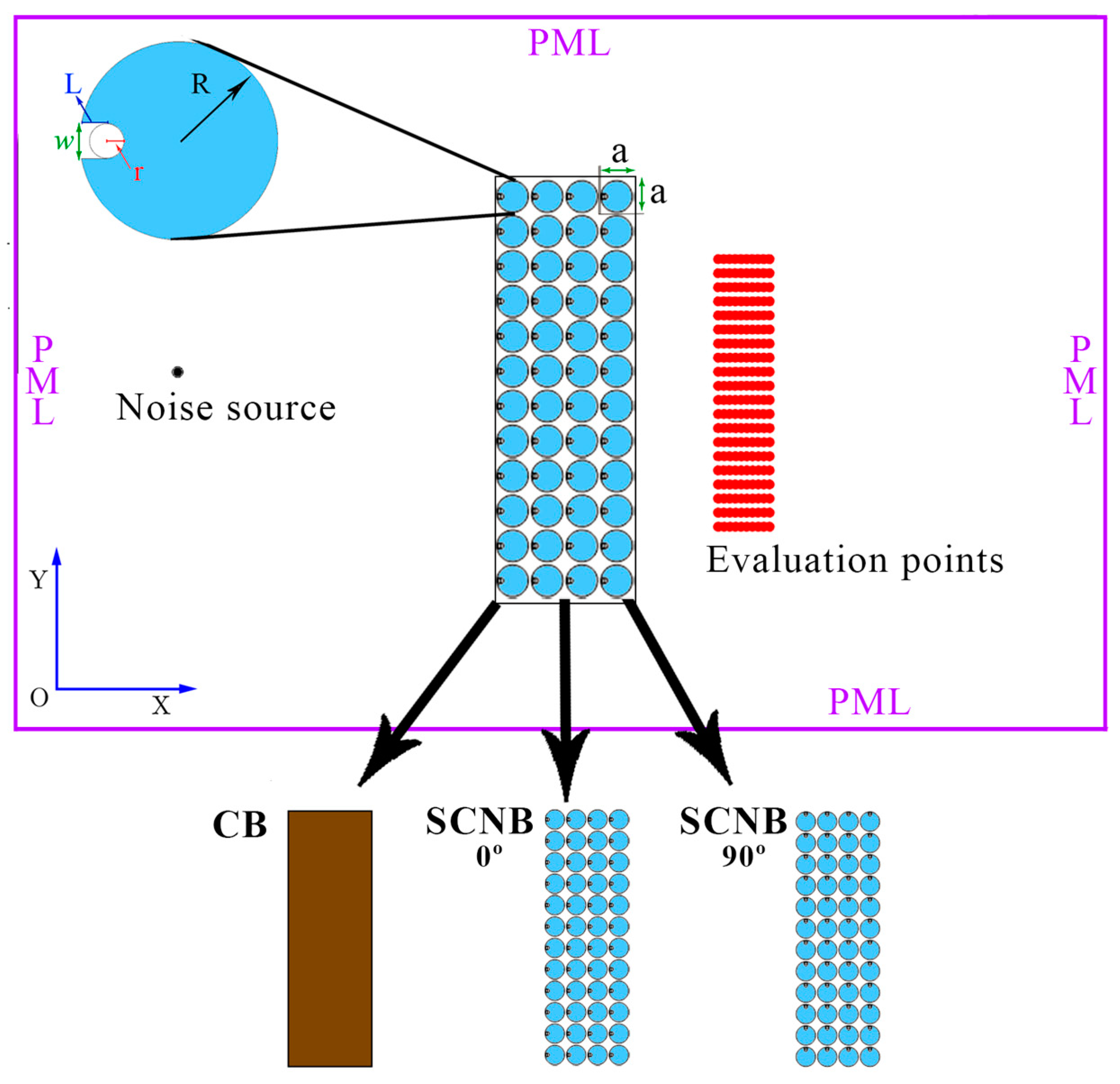
2.1. Numerical 2D Model

Finite-element method (FEM) numerical simulations with the commercial software COMSOL Multiphysics 6.1 are performed to evaluate the transmission of two-dimensional SCNBs and compare its performance with a conventional barrier (CB). The CB is a flat wall with the same dimensions as the SC ones and the SCNB consists of a set of locally resonant scatterers distributed in a square-periodic lattice with two different orientations of the resonant cavity with respect to the noise source (0° and 90°) as shown in Figure 1. By evaluating the insulation provided by the rigid flat barrier, a comparison is possible to the maximum possible level considering the border diffraction according to the SCNB dimensions.
Figure 1 illustrates the 2D SCNB model under investigation, which is defined by a square-periodic structure of 4 rows and 12 columns. The dimensions of the three barriers are the same: 11.5 cm in width (X-direction) per 0.36 m in length (Y-direction). In Figure 2b, the dimensions are shown.
The noise source is located at 30 cm from the barrier at the left part of the domain and in the centre of the barrier. It is radiating 1Pa of acoustic pressure.
It is placed in a rectangular domain of 50 cm in width (X-direction) per 80 cm in length (Y-direction). In this domain, the boundaries are perfectly matched layers (PML) [44], usually applied to absorb waves propagating outward from the domain due to their non-reflective properties.
In this 2D model, 3-node triangular elements were utilized to construct the mesh, ensuring convergence by using mesh elements with a maximum size able to evaluate 8 points per wavelength even at the maximum frequency of the study (4.5 kHz). The final geometry has a mesh of 257,168 domain elements and 128,366 boundary elements with 2,660,126 degrees of freedom.
The local resonance of the scatterers depends on the length of the neck (L), the width of the mouth (w) and the inner surface area (S = πr2), with r being the inner radius of the surface of the locally resonant scatterer. The scatterers are assumed to be rigid, neglecting the acoustic–structure coupling.
In this work, the numerical study and prototyping are carried out on a 1:2 scale model, including viscothermal losses. It is important to note that in full-scale applications, these viscothermal losses are slightly different as they are not directly scalable. Nonetheless, the research proceeds with the understanding that the variations in viscothermal losses do not critically impact the fundamental acoustic performance of the SCNB for reducing TBN. These viscothermal losses in the medium are implemented in the local resonant slit of the scatterer, according to the following equations of the complex density and the complex impedance [45]:
ρ c = ρ 0 Ψ v   k g m 3 ,
Z c 2 = ρ 0 c 2 Ψ v γ γ 1 Ψ t   P a · s m ,
where  γ  is the specific heat ratio in the air and Ψt, Ψv are the analytic expressions of the mean values of the viscous and thermal fields (φ is either v or t) in the local resonator neck:
Ψ φ = 1 tan k φ w 2 k φ w 2 ,
with  w  being the width of the mouth of the local resonator. For further details on the implementation of viscothermal losses in the FEM model, see Appendix A in [39].
The transmission of the system is analysed in the evaluation points at a distance from 0.06 m to 0.1 m from the barriers by evaluating the insertion loss (IL) in decibels defined by:
I L = 10 log 10 P d 2 P b 2   [ dB ] ,
where < > represents the average value of all evaluation points of the squared direct acoustic pressure without the barrier (Pd) and the squared acoustic pressure after placing the barrier (Pb). This parameter indicates how the sound pressure level at the evaluation points changes when the SCNB is positioned in the acoustic path of the incident wave.
Considering the TBN frequency range (2 kHz–4.5 kHz), the distribution of the scatterers in a square-lattice SCNB was chosen to have a first Bragg-BG at 3.1 kHz, being a = 0.055 m. The band structure plotted in Section 3.1 illustrates the complete Bragg-BG and the pseudo-BG in ΓX directions. In aiming to strike a balance between insulation and permeability, a filling fraction of ff = π(R/a)2 = 0.64 is established, where R represents the external radius of the scatterer.

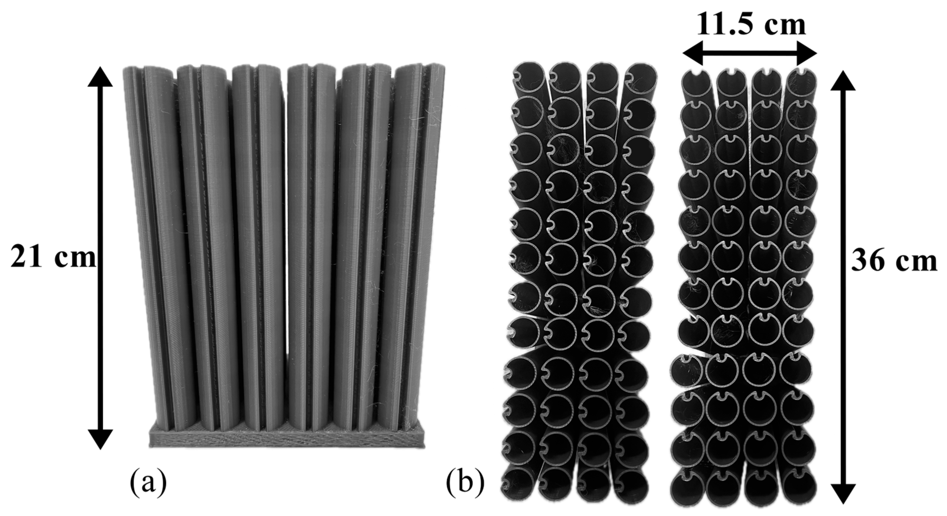
2.2. Experimental Set Up

In order to validate the resonant SCNBs experimentally, a 3D-printed prototype on a 1:2 scale was produced from polylactic acid (PLA) material. Three-dimensional printing is an advanced manufacturing technique that involves building three-dimensional objects by depositing a material layer by layer. The 3D model was created using computer-aided design (CAD) software, specifically Rhinoceros 3D (v.7.19.22165.13002) [46], to facilitate the design processes. The scaled prototype was produced using fused deposition modelling (FDM) 3D printing technology, as depicted in Figure 2. In particular, Figure 2a displays a frontal view of the SCNBs with the local resonator at 0°, while Figure 2b presents a top view of the SCNBs in the two configurations, 0° and 90°, respectively, on the left and right. Due to the size of the 3D printer, the SCNB was printed in two identical modules. One of them is shown in Figure 2a and the entire SCNB is shown in Figure 2b.
The Ultimaker S5 (Ultimaker, Utretch, The Netherlands) was used as the 3D printer due to its large printing area and high printing quality. Ultimaker PLA filament served as the printing material, processed at 220 °C with a 0.4 mm-diameter nozzle and a heated bed at 60 °C. The layer height, indicative of printing resolution, was set at approximately 100 microns. The slicing and toolpath instructions for the Ultimaker S5 were generated using CURA (version 4.13.1), an open-source slicing software selected for its compatibility with the Ultimaker S5 3D printer. CURA effectively transforms the 3D model into data suitable for execution on the Ultimaker S5 3D printer. The data are transferred in G-code format to the 3D printer, which then receives all the control information to three-dimensionally produce the prototype.
To assess the noise insulation produced by the SCNBs and to verify the importance of the orientation of the resonant cavity with respect the noise source, acoustic experiments were carried out in the anechoic chamber of the Higher Polytechnic School of Gandía. In addition, a conventional flat barrier of the same size is tested to compare the results and observe the upper and border edges diffraction limit. The dimensions of the scaled barriers are 21 cm in height, 11.5 cm in depth and 36 cm in width. A Genelec 8030A active loudspeaker is used as the sound source positioned 30 cm from the centre of the barrier, being the same distance as the 2D numerical model. Two condenser microphones, Behringer ECM8000, are used to measure the acoustic pressure at 6 cm and 10 cm of distance from the barrier. The distances of 6 cm and 10 cm were chosen to ensure placement within the “shadow zone” of the barrier according to its dimensions. Two different measurement heights at 10 cm and 12 cm were chosen to avoid possible resonances due to same wave path length. Before using them, they were calibrated with the Brüel & Kjær Sound calibrator type 4231 Class 1 (Brüel & Kjær, Nærum, Denmark), a device designed for the accurate in-field acoustic calibration of microphones and other sound measurement equipment.
They are located in the centre at a distance of 8 cm from the central edge and at a distance of 10 cm on the right and left sides of the barrier as shown in Figure 3. At these positions, the CB, the 0° SCNB, the 90° SCNB and the case without the barrier are measured to obtain the IL results.
The measurements were carried out with an M-Audio M-Track MKII soundcard and emitting sine sweeps signals from 2 to 9 kHz. In all barriers, three sine sweeps measurements were averaged. This type of signal facilitates the assessment of the impulse response for a time-invariant linear system by cross-correlating the recorded signal from the microphone.

3. Results

This section presents the numerical results of the 2D FEM model described in Section 2.1. The experimental results obtained by measuring the scaled 3D-printed prototype are then presented and finally, a comparison with the related literature of TBN barriers is made.

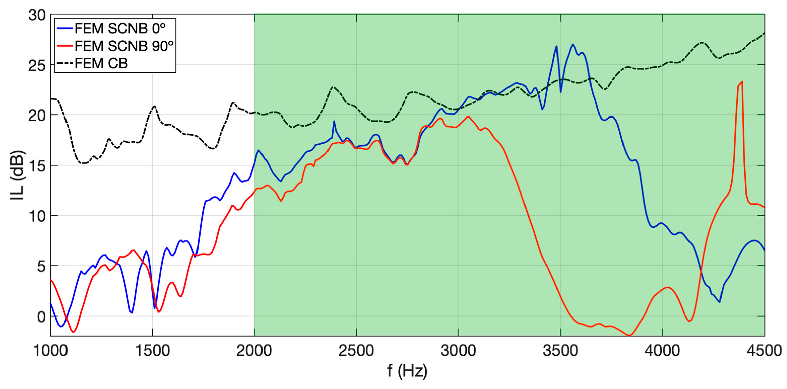
3.1. Numerical Results

Since the main purpose of SCNBs is to achieve a similar insulation level that a CB could provide, the comparison is necessary to obtain a more global picture of the case under study.
Figure 4 shows the numerical results of the FEM simulations obtained from the 2D model explained in Section 2.1. With the same dimensions as the proposed SCNB, a CB can achieve 20 to 25 dB of IL in the studied TBN frequency range (2 kHz–4.5 kHz).
The numerical IL is calculated at the evaluation points from the acoustic pressure with and without the barrier for each case, following from (4).
An open barrier such as the SCNB has lower levels but is competitive at some frequencies. One of the most important points to consider is the orientation of the mouth of the resonant cavity according to the noise source. With this rotation, a high reduction is observed when the mouth is set to 90°. In a large part of the target frequency range (2.85 to 4.2 kHz, with colour gradient) of the TBN (green colour), differences of up to 27 dB in the IL are observed when the scatterers are rotated by 90° compared to the 0° case. This reduction results in a smaller Bragg-BG and the destructive interaction of the LR-BG with the Bragg-BG. This illustrates how important it is to correctly localize the aperture of local resonators with respect to the incident noise. In addition, from 2.85 kHz to 3.7 kHz, the 0° SCNB produces similar levels of insulation compared with the CB with two peaks of maximums in the IL at approximately 3.5 kHz.
To gain a deeper insight into the noise control mechanisms that influence both 0° SCNB and 90° SCNB, the band structure is calculated with FEM simulation. With a unit-cell model, we compute the dispersion curves diagram and BG structure of two configurations of scatterers. We utilized the conventional representation using wave-vectors, where the directions ΓX correspond to specific pairs of (kx, ky) values, namely (0, 0), (π/a, 0) and (π/a, π/a), where kx and ky represent the wavenumbers in the two orthogonal directions of an infinite periodic structure with a lattice constant (a).
In Figure 5, the 0° SCNB and 90° SCNB configurations have two complete band gaps (grey colour). The first one is related to the Bragg-BG centred at 3.1 kHz, and the second one is related to the LR-BG, located at 4.37 kHz.
Examining the BG structures, computed for both the 0° SCNB and 90° SCNB, significant differences in the BG structure are observed. Specifically, the analysis of the 0° SCNB reveals the increase in the pseudo-gap around 3.1 kHz in ΓX (blue colour). For the propagation directions of interest in our experimental measurements and simulations, the relevant part of this band gap structure is between the directions ΓX.
In the case of the 0° SCNB, a pseudo-band gap is observed between 1.54 kHz and 4.28 kHz, corresponding to the target frequency range of TBN, while for 90° SCNB, it occurs between 1.73 kHz and 3.47 kHz, not covering the full range of interest.
In this section, the results of the experimental measurements are analysed and the two different configurations of SCNBs at 0° and 90° are compared.
Figure 6 shows a significant difference between the configurations in the lower frequency range (1 to 1.8 kHz), while the CB reaches levels of IL around 15 dB, and in the 0° and 90° cases, peaks about 6 and 9 dB are obtained, respectively. Nevertheless, almost in the same frequency range as the numerical result, from 2.85 kHz to 4.0 kHz, some peaks with better insulation levels are found in the experimental measurement with the 0° SCNB compared to the CB measurement. At some frequencies, such as 3.95 kHz, approximately 7 dB peaks higher insulation values are measured in the 0° SCNB case compared to the rigid barrier. This value is also observed in the numerical simulation, but with a small frequency shift. When comparing the experimental cases, it is important to consider that the maximum levels reached with the CB are the goal to achieve in the target frequency range of TBN. Due to small 3D printing defects in the small local resonator cavity, the dimensions were slightly different from model to prototype. A shift to higher frequencies can be observed throughout the frequency range, from the lowest frequency of interest to the highest peaks in the 3.5–4.0 kHz range [47]. A remarkable increase in IL is measured in the frequency range from 3.0 to 4.5 kHz, with an insulation value around 15 dB. Due to the already mentioned frequency shift and the effect of viscothermal losses (FEM model; Section 2.1), it is possible that the decrease is actually smoother and less abrupt.
From 2.85 kHz to 4.0 kHz, the insulation performance in the case of the 0° SCNB exceeds the CB, but with the 90° SCNB only poorer IL results are achieved due to the 90° rotation of all scatterers. In fact, from 2.85 to 4.5 kHz, the 90° SCNB measurement is always lower than the 0° SCNB case, resulting in a reduction in the main Bragg-BG and thus of the target frequency range where the TBN may be the most annoying.

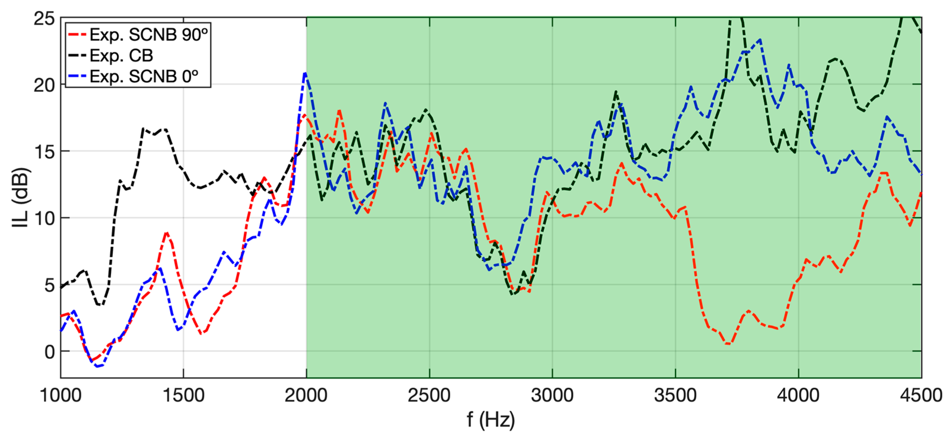
3.2. Application of the Insertion Loss Obtained via In Situ Measurements of the TBN

In this section, a practical application is developed to assess the impact of isolating a barrier in real train scenarios. This approach is intended to facilitate the evaluation of the actual sound pressure level (SPL) reduction resulting from the implementation of the barrier in a real situation. To assess the performance of these barriers, the IL obtained from the measurements described in Section 3.2 was added to the sound pressure level in the cases found in the literature regarding train noise. In particular, Jansen et al. [6] concluded that maximum levels in this frequency range were found during braking at different speeds (93, 89 and 58 km/h), and Lázaro et al. [7] measured the noise spectrum at 84 km/h and 72 km/h. Based on their measurements of the TBN, an estimate of the improvement resulting from the installation of these barriers is presented.
We start by extracting the sound pressure level (SPL) data for each case study from the existing literature. We then subtract this value the IL of the SNCB barriers measured experimentally in Section 3.2 from the TBN within the same frequency range. This method provides a clearer understanding of the barriers’ performance in realistic scenarios and allows for the assessment of their applicability. Finally, we obtain the A-weighted SPL. The results are shown in Table 1.
The perceived SPL is lower in all cases when considering the IL provided by the 0° and the 90° SCNB barriers. The overall improvement is greater than the just-noticeable difference (JND) of 1 dBA, indicating that the reduction is not only measurable but also perceptibly significant [48]. These results provide an overview of the performance of the SCNB insulation and show that the SCNB at 0° outperforms the SCNB 90° in all cases evaluated.

4. Conclusions

This work introduces the issue of noise pollution, particularly that posed by TBN in the 2 to 4.5 kHz range. The most annoying frequencies of TBN are mitigated by the introduction of SCNBs, which strategically attenuate noise within certain frequency ranges, offering a promising solution for this type of noise. More specifically, large differences were observed in numerical simulations (20 dB) and in the experimental results (25 dB) between the 0° SCNB and the 90° SCNB in the TBN frequency range.
The present research explores the integration of LRs and their interaction with Bragg scattering in resonant SCNBs, emphasizing the crucial role of resonator orientation. Advanced numerical simulations, employing FEM, assess the acoustic efficacy of 2D SCNB models, while experimental validation using 3D-printed prototypes confirms their competitive noise reduction levels compared to conventional barriers.
The appropriate configuration of the SCNBs, particularly the orientation of the resonant cavity, proves to be crucial for effective noise reduction, especially when the local resonators are oriented at 0°. Our study designed for the specific frequency range of TBN, from 2 kHz to 4.5 kHz, focusing on this spectrum allows for in-depth analysis and targeted solutions for TBN mitigation. Additionally, we highlight the potential for scalability of our findings, with a note that large-scale applications should consider the role of viscothermal losses. This opens avenues for future research, allowing for the exploration of our model’s adaptability and its impact across various scales and contexts. The study opens up new avenues for future investigations in noise reduction and SCNBs. Potential future research areas include exploring scalability to diverse transportation environments, optimizing SCNB materials and resonator designs, integrating smart technologies for active noise mitigation and assessing long-term durability and maintenance requirements.

Author Contributions

Conceptualization, D.R.-S., J.G.-N., J.R. and R.P.; methodology, J.G.-N., D.R.-S., V.S., A.V.G., N.P., J.R. and R.P.; software, D.R.-S., V.S., A.V.G., N.P. and R.P.; validation, J.R. and R.P.; formal analysis, J.G.-N., D.R.-S., J.R. and R.P.; investigation, J.G.-N., V.S., A.V.G., N.P., J.R. and R.P.; resources, V.S., A.V.G., N.P., J.R. and R.P.; data curation, J.G.-N. and D.R.-S.; writing—original draft preparation, D.R.-S. and J.G.-N.; writing—review and editing, J.G.-N., D.R.-S., V.S., A.V.G., N.P., J.R. and R.P.; visualization, J.G.-N. and D.R.-S.; supervision, J.R. and R.P; project administration, V.S., A.V.G., N.P., J.R. and R.P.; funding acquisition, V.S., A.V.G., N.P. and R.P. All authors have read and agreed to the published version of the manuscript.

Funding

This work was supported by the Spanish Ministry of Economy and Innovation (MINECO) and the European Union FEDER (project PID2019-109175GB-C22).

Data Availability Statement

The raw data supporting the conclusions of this article will be made available by the authors on request.

Acknowledgments

The authors acknowledge FabLab Bitonto and Enrique Anastasio Späth.

Conflicts of Interest

The authors declare no conflicts of interest.

References

  1. European Commission; Directorate General for Environment; The European Parliament and the Council of the European Union. Implementation of the Environmental Noise Directive in Accordance with Article 11 of Directive 2002/49/EC; European Comission: Brussels, Belgium, 2023.
  2. Lin, J.-Y.; Cheng, W.-J.; Wu, C.-F.; Chang, T.-Y. Associations of Road Traffic Noise and Its Frequency Spectrum with Prevalent Depression in Taichung, Taiwan. Front. Public Health 2023, 11, 1116345. [Google Scholar] [CrossRef]
  3. Polak, K.; Korzeb, J. Modelling the Acoustic Signature and Noise Propagation of High Speed Railway Vehicle. Arch. Transp. 2022, 64, 73–87. [Google Scholar] [CrossRef]
  4. Chiello, O.; Sinou, J.-J.; Vincent, N.; Vermot Des Roches, G.; Cocheteux, F.; Bellaj, S.; Lorang, X. Squeal Noise Generated by Railway Disc Brakes: Experiments and Stability Computations on Large Industrial Models. J. Acoust. Soc. Am. 2013, 133, 3461. [Google Scholar] [CrossRef]
  5. Cascetta, F.; Caputo, F.; De Luca, A. Squeal Frequency of a Railway Disc Brake Evaluation by FE Analyses. Adv. Acoust. Vib. 2018, 2018, 4692570. [Google Scholar] [CrossRef]
  6. Jansen, E.H.; Dittrich, M.G.; Sikma, E.L. Brake Noise Measurements on Mixed Freight Trains with Composite Brake Blocks. J. Acoust. Soc. Am. 2008, 123, 3266. [Google Scholar] [CrossRef]
  7. Lázaro, J.; Pereira, M.; Costa, P.A.; Godinho, L. Performance of Low-Height Railway Noise Barriers with Porous Materials. Appl. Sci. 2022, 12, 2960. [Google Scholar] [CrossRef]
  8. Tickell, C.E.; Downing, P.; Jacobsen, C.J. Rail Wheel Squeal—Some Causes and a Case Study of Freight-Car Wheel Squeal Reduction. In Proceedings of the Acoustics 2004, Gold Coast, Australia, 3 November 2004; pp. 239–244. [Google Scholar]
  9. Harris, C.M. Handbook of Acoustical Measurements and Noise Control; McGraw-Hill: New York, NY, USA, 1991; pp. 3019–3020. [Google Scholar]
  10. Maekawa, Z. Noise Reduction by Screens. Appl. Acoust. 1968, 1, 157–173. [Google Scholar] [CrossRef]
  11. Branco, F.J.F.G.; Godinho, L.; Tadeu, A. Acoustic Insertion Loss Provided by Rigid Acoustic Barriers of Different Shapes. J. Comput. Acoust. 2003, 11, 503–519. [Google Scholar] [CrossRef]
  12. Jolibois, A.; Defrance, J.; Koreneff, H.; Jean, P.; Duhamel, D.; Sparrow, V.W. In Situ Measurement of the Acoustic Performance of a Full Scale Tramway Low Height Noise Barrier Prototype. Appl. Acoust. 2015, 94, 57–68. [Google Scholar] [CrossRef]
  13. Sousa, L.; Pereira, L.; Montes-González, D.; Ramos, D.; Amado-Mendes, P.; Barrigón-Morillas, J.M.; Godinho, L. Experimental Analysis and Simulation of a Porous Absorbing Layer for Noise Barriers. Appl. Sci. 2023, 13, 2638. [Google Scholar] [CrossRef]
  14. Fusaro, G.; Garai, M. Acoustic Requalification of an Urban Evolving Site and Design of a Noise Barrier: A Case Study at the Bologna Engineering School. Appl. Sci. 2024, 14, 1837. [Google Scholar] [CrossRef]
  15. Sanchez-Perez, J.V.; Rubio, C.; Martinez-Sala, R.; Sanchez-Grandia, R.; Gomez, V. Acoustic Barriers Based on Periodic Arrays of Scatterers. Appl. Phys. Lett. 2002, 81, 5240–5242. [Google Scholar] [CrossRef]
  16. Kushwaha, M.S. Stop-Bands for Periodic Metallic Rods: Sculptures That Can Filter the Noise. Appl. Phys. Lett. 1997, 70, 3218–3220. [Google Scholar] [CrossRef]
  17. D’Orazio, T.; Asdrubali, F.; Godinho, L.; Veloso, M.; Amado-Mendes, P. Experimental and Numerical Analysis of Wooden Sonic Crystals Applied as Noise Barriers. Environments 2023, 10, 116. [Google Scholar] [CrossRef]
  18. Morandi, F.; Miniaci, M.; Marzani, A.; Barbaresi, L.; Garai, M. Standardised Acoustic Characterisation of Sonic Crystals Noise Barriers: Sound Insulation and Reflection Properties. Appl. Acoust. 2016, 114, 294–306. [Google Scholar] [CrossRef]
  19. Martínez-Sala, R.; Sancho, J.; Sánchez-Pérez, J.V.; Gómez, V.; Llinares, J.; Meseguer, F. Sound Attenuation by Sculpture. Nature 1995, 378, 241. [Google Scholar] [CrossRef]
  20. Yang, W.; Ouyang, D.; Deng, E.; He, X.; Zou, Y.; Huang, Y. Aerodynamic Characteristics of Two Noise Barriers (Fully Enclosed and Semi-Enclosed) Caused by a Passing Train: A Comparative Study. J. Wind Eng. Ind. Aerodyn. 2022, 226, 105028. [Google Scholar] [CrossRef]
  21. Zheng, J.; Li, Q.; Li, X.; Luo, Y. Train-Induced Fluctuating Pressure and Resultant Dynamic Response of Semienclosed Sound Barriers. Shock Vib. 2020, 2020, 6901564. [Google Scholar] [CrossRef]
  22. Minelli, G.; Yao, H.-D.; Andersson, N.; Lindblad, D.; Forssén, J.; Höstmad, P.; Krajnović, S. Using Horizontal Sonic Crystals to Reduce the Aeroacosutic Signature of a Simplified ICE3 Train Model. Appl. Acoust. 2021, 172, 107597. [Google Scholar] [CrossRef]
  23. Wu, X.; He, X.; Huang, J. Comparative Analysis of Dynamic Responses of Different Types of High-Speed Railway Noise Barriers under the Influence of Fluctuating Wind Pressure. Sustainability 2022, 14, 12900. [Google Scholar] [CrossRef]
  24. Economou, E.N.; Sigalas, M.M. Elastic and Acoustic Wave Band Structure. J. Sound Vib. 1992, 158, 377–382. [Google Scholar]
  25. Chen, Y.-Y.; Ye, Z. Theoretical Analysis of Acoustic Stop Bands in Two-Dimensional Periodic Scattering Arrays. Phys. Rev. E 2001, 64, 036616. [Google Scholar] [CrossRef] [PubMed]
  26. Kittel, C. Introduction to Solid State Physics, 8th ed.; Wiley: Hoboken, NJ, USA, 2005; ISBN 978-0-471-41526-8. [Google Scholar]
  27. Zhang, S.; Liu, J.; Zhang, H.; Wang, S. Tunable Low Frequency Band Gap and Waveguide of Phononic Crystal Plates with Different Filling Ratio. Crystals 2021, 11, 828. [Google Scholar] [CrossRef]
  28. Miyashita, T. Sonic Crystals and Sonic Wave-Guides. Meas. Sci. Technol. 2005, 16, R47–R63. [Google Scholar] [CrossRef]
  29. Redondo, J.; Picó, R.; Sánchez-Morcillo, V.J.; Woszczyk, W. Sound Diffusers Based on Sonic Crystals. J. Acoust. Soc. Am. 2013, 134, 4412–4417. [Google Scholar] [CrossRef]
  30. Lee, H.M.; Hua, Y.; Xie, J.; Lee, H.P. Parametric Optimization of Local Resonant Sonic Crystals Window on Noise Attenuation by Using Taguchi Method and ANOVA Analysis. Crystals 2022, 12, 160. [Google Scholar] [CrossRef]
  31. Li, X.-L.; Lam, W.K.; Tang, S.K. Experimental Investigation on the Enhancement of Plenum Window Noise Reduction Using Solid Scatterers. J. Acoust. Soc. Am. 2023, 153, 1361–1374. [Google Scholar] [CrossRef]
  32. Lardeau, A.; Groby, J.-P.; Romero-García, V. Broadband Transmission Loss Using the Overlap of Resonances in 3D Sonic Crystals. Crystals 2016, 6, 51. [Google Scholar] [CrossRef]
  33. Liu, Z.; Zhang, X.; Mao, Y.; Zhu, Y.Y.; Yang, Z.; Chan, C.T.; Sheng, P. Locally Resonant Sonic Materials. Science 2000, 289, 1734–1736. [Google Scholar] [CrossRef]
  34. Lagarrigue, C.; Groby, J.P.; Tournat, V.; Dazel, O.; Umnova, O. Absorption of Sound by Porous Layers with Embedded Periodic Arrays of Resonant Inclusions. J. Acoust. Soc. Am. 2013, 134, 4670–4680. [Google Scholar] [CrossRef]
  35. Cavalieri, T.; Cebrecos, A.; Groby, J.-P.; Chaufour, C.; Romero-García, V. Three-Dimensional Multiresonant Lossy Sonic Crystal for Broadband Acoustic Attenuation: Application to Train Noise Reduction. Appl. Acoust. 2019, 146, 1–8. [Google Scholar] [CrossRef]
  36. Romero-García, V.; Sánchez-Pérez, J.V.; Garcia-Raffi, L.M. Tunable Wideband Bandstop Acoustic Filter Based on Two-Dimensional Multiphysical Phenomena Periodic Systems. J. Appl. Phys. 2011, 110, 014904. [Google Scholar] [CrossRef]
  37. Yuan, B.; Humphrey, V.F.; Wen, J.; Wen, X. On the Coupling of Resonance and Bragg Scattering Effects in Three-Dimensional Locally Resonant Sonic Materials. Ultrasonics 2013, 53, 1332–1343. [Google Scholar] [CrossRef]
  38. Cenedese, M.; Belloni, E.; Braghin, F. Interaction of Bragg Scattering Bandgaps and Local Resonators in Mono-Coupled Periodic Structure. J. Appl. Phys. 2021, 129, 124501. [Google Scholar] [CrossRef]
  39. Redondo, J.; Ramírez-Solana, D.; Picó, R. Increasing the Insertion Loss of Sonic Crystal Noise Barriers with Helmholtz Resonators. Appl. Sci. 2023, 13, 3662. [Google Scholar] [CrossRef]
  40. Peiró-Torres, M.P.; Castiñeira-Ibáñez, S.; Redondo, J.; Sánchez-Pérez, J.V. Interferences in Locally Resonant Sonic Metamaterials Formed from Helmholtz Resonators. Appl. Phys. Lett. 2019, 114, 171901. [Google Scholar] [CrossRef]
  41. Redondo, J.; Godinho, L.; Staliunas, K.; Vicente Sánchez-Pérez, J. An Equivalent Lattice-Modified Model of Interfering Bragg Bandgaps and Locally Resonant Stop Bands for Phononic Crystal Made from Locally Resonant Elements. Appl. Acoust. 2023, 211, 109555. [Google Scholar] [CrossRef]
  42. Peiró-Torres, M.P.; Parrilla Navarro, M.J.; Ferri, M.; Bravo, J.M.; Sánchez-Pérez, J.V.; Redondo, J. Sonic Crystals Acoustic Screens and Diffusers. Appl. Acoust. 2019, 148, 399–408. [Google Scholar] [CrossRef]
  43. Ramírez-Solana, D.; Redondo, J.; Mangini, A.M.; Fanti, M.P. Particle Swarm Optimization of Resonant Sonic Crystals Noise Barriers. IEEE Access 2023, 11, 38426–38435. [Google Scholar] [CrossRef]
  44. Berenger, J.-P. A Perfectly Matched Layer for the Absorption of Electromagnetic Waves. J. Comput. Phys. 1994, 114, 185–200. [Google Scholar] [CrossRef]
  45. Stinson, M.R. The Propagation of Plane Sound Waves in Narrow and Wide Circular Tubes, and Generalization to Uniform Tubes of Arbitrary Cross-Sectional Shape. J. Acoust. Soc. Am. 1991, 89, 550–558. [Google Scholar] [CrossRef]
  46. Rhinoceros 3D. (2023, November). Rhinoceros 3D Website. Available online: https://www.rhino3d.com/ (accessed on 19 January 2024).
  47. Fusaro, G.; Barbaresi, L.; Cingolani, M.; Garai, M.; Ida, E.; Prato, A.; Schiavi, A. Investigation of the Impact of Additive Manufacturing Techniques on the Acoustic Performance of a Coiled-Up Resonator. J. Acoust. Soc. Am. 2023, 153, 2921. [Google Scholar] [CrossRef] [PubMed]
  48. Redondo, J.; Gaja-Silvestre, P.; Godinho, L.; Amado-Mendes, P. A Simple Method to Estimate the In Situ Performance of Noise Barriers. Appl. Sci. 2022, 12, 7027. [Google Scholar] [CrossRef]
Figure 1. Numerical FEM model of the resonant scatter at 0° and 90° (upper part), simulation domain with the 4 × 12 SCNB at 0° (middle part) and the three different barriers, CB, SCNB 0° and SCNB 90° (lower part).
Applsci 14 02753 g001
Figure 2. 3D-printed 1:2 scaled SCNB PLA prototypes: (a) Front view of the scaled SCNBs with the local resonator at 0°; (b) Top view of the scaled SCNBs at the 0° and 90° configurations.
Applsci 14 02753 g002
Figure 3. Experimental set up measurement system: (a) SCNB measurement; (b) CB measurement.
Applsci 14 02753 g003
Figure 4. Insertion loss of numerical FEM models with 0° SCNB (blue), 90° SCNB (red) and CB (black).
Applsci 14 02753 g004
Figure 5. Band structure diagrams for the 0° SCNB (left) and 90° SCNB (right), both including the unit cell of the two-dimensional scatterer with LR, which forms the periodic system defining the SCNB and irreducible Brillouin zone of the square lattice SC based on the Bloch–Floquet theory for the calculation of the band structure.
Applsci 14 02753 g005
Figure 6. Insertion loss of the experimental measurements, with experimental 0° SCNB (blue dot-dashed), experimental 90° SCNB (red dot-dashed) and experimental CB (black dot-dashed).
Applsci 14 02753 g006
Table 1. Comparison of the A-weighted SPL in dBA for each SCNB arrangement at 0° and 90° when added to real cases of TBN measurements.
CaseSPL without Barrier
(dBA)
SPL SCNB 0°
(dBA)
SPL SCNB 90°
(dBA)
Jansen et al. [6] (1)71.363.463.6
Jansen et al. [6] (2)77.970.771.0
Jansen et al. [6] (3)78.268.969.7
Lázaro et al. [7] (1)80.166.269.4
Lázaro et al. [7] (2)79.575.475.3
Lázaro et al. [7] (3)68.855.258.2
Disclaimer/Publisher’s Note: The statements, opinions and data contained in all publications are solely those of the individual author(s) and contributor(s) and not of MDPI and/or the editor(s). MDPI and/or the editor(s) disclaim responsibility for any injury to people or property resulting from any ideas, methods, instructions or products referred to in the content.

