
Research on Out-of-Plane Bending Test of PVB Laminated Glass Plate with Different Number of Layers

1
College of Water Resources and Architectural Engineering, Northwest A&F University, Xianyang 712100, China
2
Deepwater Engineering Research Center, Dalian University of Technology, Dalian 116081, China
3
Ningbo Institute, Dalian University of Technology, Ningbo 315032, China
*
Authors to whom correspondence should be addressed.
Appl. Sci. 2024, 14(8), 3416; https://doi.org/10.3390/app14083416
Submission received: 7 March 2024
/
Revised: 11 April 2024
/
Accepted: 12 April 2024
/
Published: 18 April 2024
(This article belongs to the Section Civil Engineering)
Abstract
:Polyvinyl Butyral (PVB) laminated glass (LG) with varying numbers of layers is extensively utilized in building structures, and its complex mechanical properties, due to the presence of PVB, pose significant challenges. While comprehensive research has been conducted on the bending behavior of two-layer PVB laminated glass, studies focusing on three-layer variants remain limited. This study aims to investigate the bending behavior of three-layer PVB laminated glass under out-of-plane forces and to ascertain the effects of increasing the number of layers. Experimental studies were carried out on one-, two-, and three-layer PVB laminated glass plates subjected to such loads. During the loading process, the out-of-plane displacement and surface strain of the glass plates were monitored and analyzed. From these observations, load-deflection curves were constructed, allowing for the determination of deflection and strain distribution across the planes. The impact of the number of glass layers on stiffness and ultimate load capacity was examined. Additionally, another experiment was conducted to analyze the mechanical properties of the laminated material (PVB). The research results indicate that the tensile strain at the bottom layer of the laminated glass plate reaches its threshold under an out-of-plane load, leading to a brittle fracture in that layer. However, the remaining layers of PVB LG do not fail at this stage, enabling the plate to continue bearing the load. The average ultimate loads for three-layer, two-layer, and one-layer PVB laminated glass are 37.8 kN, 36 kN, and 24.7 kN, respectively, with a ratio of 1:0.95:0.65. The bending stiffness values for these are 2.77 kN/mm, 1.71 kN/mm, and 1.21 kN/mm, respectively, corresponding to a ratio of 1:0.62:0.44. The stiffness shows a nonlinear increase with the layer count, an effect attributed to the PVB’s characteristics according to the analytical findings. The tensile behavior of the laminated materials demonstrates a bilinear characteristic when subjected to strain. The out-of-plane bending tests on glass plates reveal that when the strain rate is low, PVB behaves like a quasi-linear elastic material. Therefore, for design calculations of PVB LG, adopting an elastic modulus of 1.34 MPa for PVB is deemed reasonable. The findings of this study provide insights for research on laminated glass plates, which are instrumental in refining the calculation methods specified in relevant design standards. Concurrently, it offers guidance for selecting the appropriate number of PVB LG layers in engineering applications.
1. Introduction
As a type of high-strength translucent composite plate, the Polyvinyl Butyral (PVB) laminated glass plate (LG) is manufactured by hot-pressing multiple borosilicate glass plates with an interlayer of PVB. Owing to its excellent transparency, high strength, and superior physical isolation properties, PVB LG has been extensively employed in buildings, vehicles, and various other structures since its inception in 1903. Initially, PVB LG was predominantly used as a decorative feature in buildings, but with advancements in manufacturing technology and architecture, its application as a load-bearing element has become increasingly prevalent. A glass floor is a quintessential example of such use. To resist out-of-plane loads exerted by people, vehicles, and other entities, the number of glass layers in PVB LG is carefully selected, often comprising two or three layers. As a laminated component, its mechanical behavior is intricately influenced by both the PVB interlayer and the glass layers, rendering its properties exceedingly complex. Overestimating its load-bearing capacity can lead to dire consequences, whereas underestimating it can cause considerable material wastage. In light of this, accurately determining the mechanical response characteristics of laminated glass plates under out-of-plane loads is essential for their rational structural design [1].
The bending behavior of PVB laminated glass panels is complex, partly because the elastic modulus of PVB is significantly lower than that of borosilicate glass. Despite both materials being isotropic, this discrepancy in elastic modulus means that when PVB laminated glass is subjected to bending out of plane, PVB’s low elastic modulus cannot adequately support the coordinated deformation of each glass layer. Consequently, a certain degree of in-plane relative sliding occurs at the interfaces between glass layers. It has been established that the flexural stiffness of laminated glass plates is lower compared to a single-layer plate of the same thickness [2]. The extent of this relative slippage is influenced by the shear stress provided by PVB, which is closely related to its elastic modulus [3]. Given that PVB is a non-linear constitutive polymer material [4], this adds to the complexity of the bending behavior of PVB laminated glass. In response to this complexity, scholars have undertaken theoretical research on the bending behavior of laminated glass under various operational conditions and mechanical hypotheses. For glass plates with unidirectional support, the plates can be simplified into an equivalent superposed beam, which reduces the number of generalized variables in the control equation and simplifies the solution process [5]. Hooper et al. [6] derived an analytical solution for an equivalent beam with simple support under four-point bending and compression, confirming the solution’s validity. Asik et al. [7] extended equivalent beam theory to three-layer glass plates, derived the control differential equation by accounting for shear deformation in the laminated layer, and used the variational method to obtain a theoretical solution. However, the layered beam theory may not capture all complexities of the plates. Asik et al. [8] applied a variational approach to the partial differential equations of laminated plates, yielding an analytical solution for the non-linear bending of these plates. Vallabhan et al. [9] employed the Finite Difference Method (FDM) to discretize the bending partial differential equation for laminated glass plates, offering a convergent solution.
Presenting an analytical solution directly is challenging due to the complexity involved in applying classical shell theory to laminated glass plates and the influence of numerous generalized variables, which limits its practicality. Consequently, in structural design practice, the equivalent thickness method is commonly used to compute the bending resistance of laminated glass plates. This method facilitates the application of classical analytical solutions, devised for single-layer plates, to laminated plates. Owing to its simplicity, this approach has been adopted in glass plate specifications across many countries [10,11,12,13]. However, these specifications differ in the methodology used to determine the equivalent thickness of laminated glass plates. Additionally, variations in the equivalent principle lead to discrepancies in measured equivalent thickness [14,15,16,17]. Theoretical studies have mainly focused on the bending calculations of two-layer PVB LG, with limited research on three-layer PVB LG. Furthermore, these studies typically assume the elastic modulus of PVB to be a constant value for calculations, ignoring the material’s nonlinearity [17]. The validity of such an assumption remains in question and requires verification.
Due to the high complexity involved in achieving a closed-form solution using lamination theory, finite element numerical analysis has become another popular method for studying the mechanical response of laminated glass plates. Typically, the finite element analysis of a laminated glass plate involves multi-layer plate elements for numerical simulation, introducing the constitutive model of PVB to simulate the relative slip between the plates. This finite element model is suitable for analyzing how various factors, such as the number of glass layers, temperature, and adhesive thickness, affect the mechanical properties of laminated glass plates. Biolzi et al. [18] performed numerical analyses to investigate the effects of plate size, interlayer thickness, glass thickness, and the number of glass layers on bending behavior, indicating that plate size significantly influences the analytical results. Through finite element parametric analysis, Galic et al. [19] assessed the impact of temperature, load duration, and laminate thickness on the deflection of the entire plate and the stress distribution within it, leading to the proposal of an approximate method for calculating the bending stiffness of the plate. Ali et al. [20] used the improved zig-zag theory to develop numerical methods suitable for general working conditions and presented an analytical solution for statically determinate beams by treating the glass plate as an Euler beam and considering the adhesive layer as solely providing shear stiffness for coupling the glass layers. Jaśkowiec et al. [21] created a 3D modeling approach for bending laminated glass plates using a 2D planar grid and completed a visualization post-processing program. They utilized this method to compute the bending of laminated glass with two, three, and four layers of glass and analyzed the accuracy of the calculated results. Vedrtam et al. [22] employed ANSYS for numerical simulations of laminated glass, unveiling a strong correlation between bending stiffness and the type and thickness of the laminate material. Yongjiu S. et al. [23] developed a finite element model for PVB laminated glass supported at four points, examining the effect of load duration on maximum deflection and finding that prolonged loading can diminish the bending resistance of PVB laminated glass. Wen W. et al. [24] carried out finite element analyses of PVB laminated glass with varying thicknesses for each glass layer, discovering that a significant discrepancy in layer thicknesses can increase deflection, thereby reducing load-bearing capacity. Bending stiffness is the physical quantity that most directly indicates a plate’s ability to resist bending deformation. Although existing numerical simulations have explored the deformation of different layers of PVB LG, none have quantitatively analyzed the effect of the number of glass layers on bending stiffness. Moreover, the numerical simulation of three-layer PVB LG still lacks experimental validation.
Conducting bending experiments on laminated glass plates is considered the most vital method for analyzing their mechanical response [25], providing a means for theoretical verification and numerical analysis. Researchers have focused on double-layered glass plates to experiment with the load-bearing capacity of laminated glass under bending conditions. Zhang et al. [26] performed bending load tests on cold-bent laminated glass with varying cold bending rates and interlayer thicknesses. Cold-bent glass is produced by applying external forces to flat glass to induce deformation, permanently setting it to the desired curved shape, with the cold bending rate defined as the curvature of the curved arc. They observed that the ultimate load-bearing capacity of laminated glass decreases with an increase in both the cold bending rate and the interlayer thickness. Vedrtnam et al. [22] conducted a three-point bending test to study the impact of a non-uniform thermal gradient on the bending performance of laminated glass. They demonstrated that the bending deformation of laminated glass under heating is significantly more pronounced than that without heating, with residual deformation being observable after unloading. In addition, Vedrtnam et al. [27] measured the flexural strength of laminated glass with various interlayer materials and thicknesses. The experimental results indicated that PVB laminated glass exhibits a greater extent of average deformation and can bear a higher average load compared to vinyl acetate laminated glass. The average pre-fracture deformation was found to increase with the rise in interlayer thickness. Mohagheghian et al. [28] investigated the influence of polymer interlayer thickness, glass, and polymer type on structural performance through static and low-speed loading experiments on laminated glass. Their analysis focused on the effects of interlayer type, thickness, and loading method on the fracture patterns of each glass layer. Huang et al. [29] conducted bending experiments on two types of laminated materials under four-sided simple support, discovering that the bending stiffness of LG with polymer interlayers increases with a rise in the thickness of the lamination. However, the LG with a polyvinyl butyral interlayer exhibited insensitivity to changes in interlayer thickness, provided there was no significant deflection bending. Vallabhan et al. [9] performed a four-point bending test on LG plates to compare the effects of temperature, load duration, and adhesive thickness on the overall deflection and stress distribution within the plate. They presented an approximate calculation method for determining the bending stiffness of the plate. Although scholars have conducted experimental studies on various factors affecting the bending behavior of laminated glass, these studies have predominantly focused on two-layer glass plates, with no experimental studies on three-layer glass plates. The relationship between the number of glass layers and the ultimate load-carrying capacity of PVB laminated glass, as well as the relationship between the number of layers and the bending stiffness of PVB laminated glass, remain to be further researched.
To study the influence of the number of glass layers on the bending behavior of PVB LG (Trading Company, Guangzhou, China), and to address the gap in experimental research on three-layer PVB LG, this study conducted and analyzed bending experiments on one-layer, two-layer, and three-layer PVB LG under out-of-plane loading. During the loading process, the out-of-plane displacement and surface strain of the glass plate were monitored and analyzed. Load-deflection curves were plotted based on these observations, and the distribution of deflection and strain in the plane was obtained. The influence of layer count on stiffness and ultimate load was examined. Surprisingly, it was found that the stiffness of PVB LG does not increase linearly with the number of layers. By calculating and comparing the stiffness of LG when the effect of PVB is completely disregarded, it was revealed that the nonlinearity is attributed to the PVB. Moreover, this study provides a value for the elastic modulus suitable for PVB LG bending calculations through material testing of PVB. This study offers experimental evidence to support the theoretical and numerical simulation of PVB LG and serves as a reference for selecting the number of layers in engineering applications. Additionally, the recommended elastic modulus of PVB provided in this paper can be used as a reference in design calculations.
2. Materials and Methods
2.1. Mechanical Properties of PVB
PVB is a nonlinear constitutive material, with its elastic modulus varying at different strain stages [29,30,31,32]. However, in the design calculations for LG, the elastic modulus of PVB is often assumed to be a constant value to simplify the calculations, and this value is not universally agreed upon [10]. To determine whether it is reasonable to consider the elastic modulus as a constant value, and to provide recommended values, this study conducted experiments to assess the mechanical properties of PVB.
2.1.1. PVB Sample Design
The PVB specimens were designed in accordance with ISO 3537 (Road vehicles-Safety glazing materials-Mechanical tests) [33], as depicted in Figure 1, with their specific dimensions provided in Table 1. All PVB samples for testing were peeled from the same batch of PVB laminated glass and were cut into the standard shapes specified in the standard. According to the standard, the tensile speeds were set at 10 mm/min and 20 mm/min, which allowed fractures to occur within 0.5–5 min during preliminary experiments. The specimens were divided into two groups, each consisting of five specimens with identical specifications. Their details are presented in Table 1.
2.1.2. Test Setup
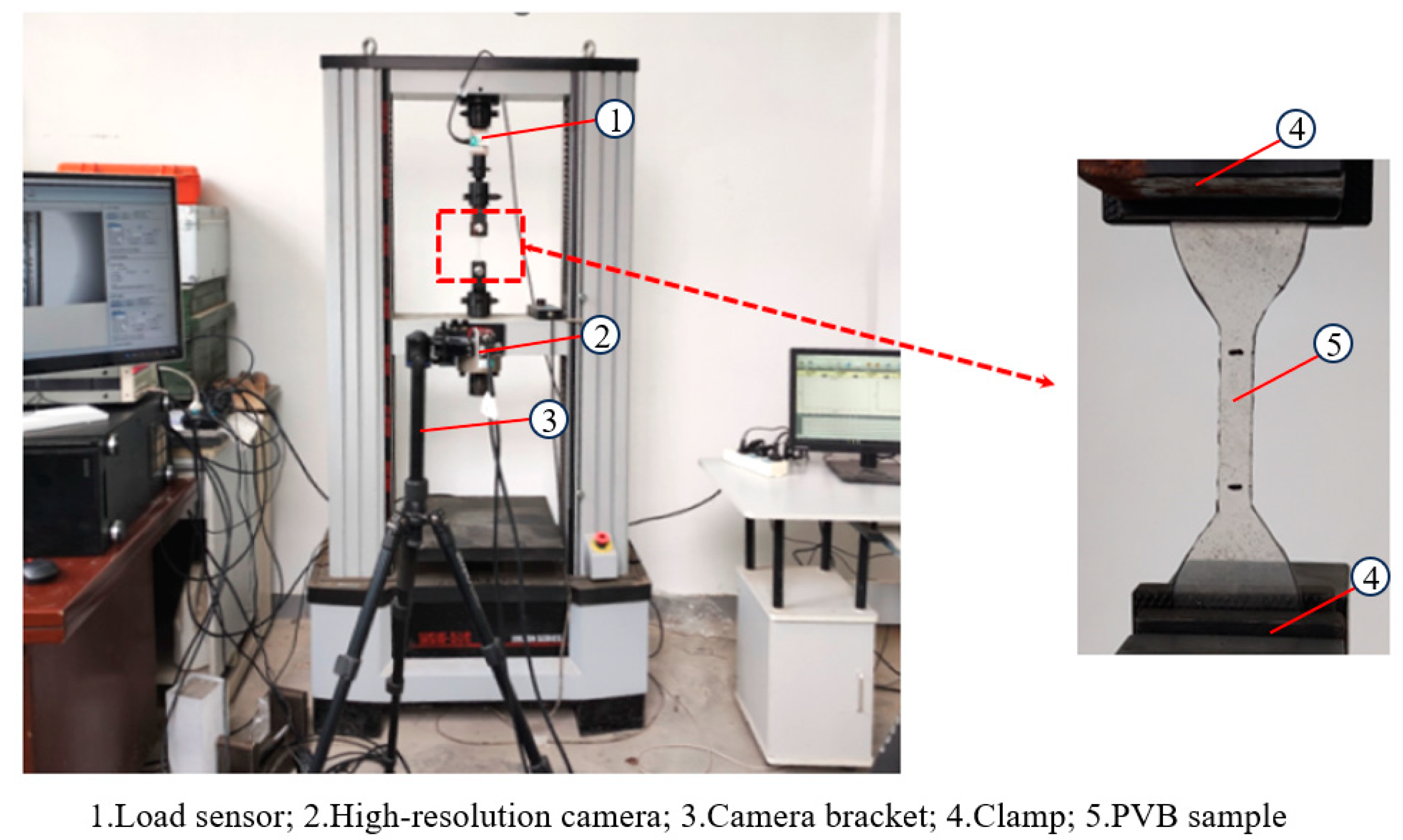
The mechanical property tests of PVB were conducted in the Structural Laboratory at the School of Water Architecture, Northwest A&F University. Figure 2 illustrates the experimental setup for the PVB tensile testing. During these tests, the PVB specimen was stretched axially at a constant speed until fracture occurred. A load sensor was installed at the position indicated in Figure 2 to measure the tensile load. Additionally, a high-resolution camera was set up directly in front of the tensile tester to continuously capture the tensile process of the PVB sample at a frequency of one picture per second. The camera specifications are listed in Table 2.
2.1.3. Elastic Modulus of PVB
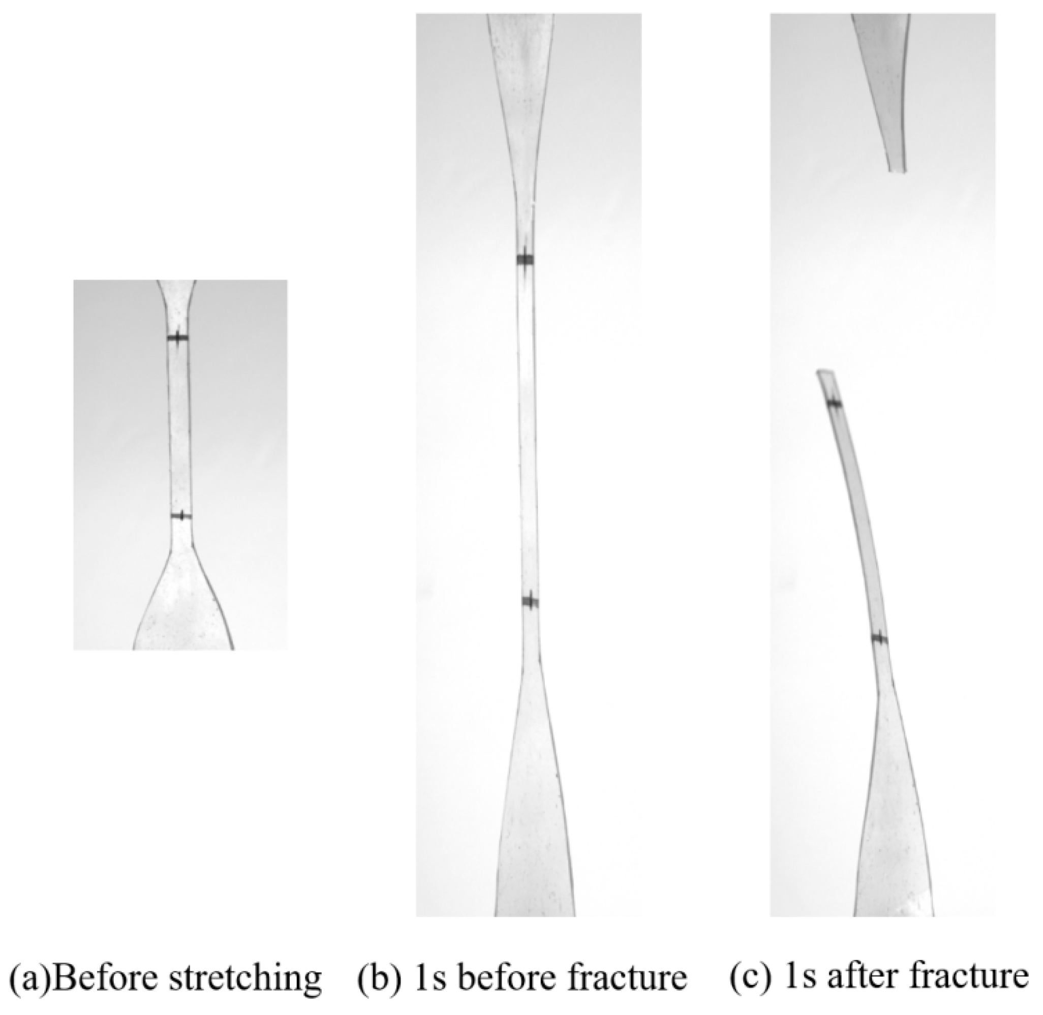
During the stretching process, the length of the specimen increased gradually, while its width decreased. Upon reaching the stretching limit, a low and dull sound, described as a “Bang”, was heard, as depicted in Figure 3. At this point, the ultimate elongation approached 200% (±10%). For the tensile test, the engineering stress (σ) is denoted in MPa, and the conditional strain (engineering strain) is expressed as (), calculated by:
where represents the load applied to the specimen, in ; denotes the cross-sectional area of the specimen before stretching, in mm2; denotes the change in the specimen’s length after stretching, in mm; and is the length of the specimen before stretching, in mm.
Figure 4 shows the engineering stress–strain relationship exhibited by all of the specimens, and Table 3 lists their experimental results, especially the mechanical properties of PVB under investigation. This stress–strain curve is similar to those obtained through quasi-static tensile tests conducted by Kluppel et al. [34] and Xu et al. [35].
The tensile curve is divided into three phases. In phase I, where the engineering strain is less than 0.6, the elastic modulus is comparatively low, and the engineering stress–engineering strain curve is almost linear. This observation is consistent with the findings of Rong and Chen [36], who stated that the stress–strain relationship of PVB is essentially linear under quasi-static conditions and with minimal deformation. On average, the initial elastic modulus of PVB materials is 1.34 MPa at a tensile speed of 10 mm/min and 1.54 MPa at 20 mm/min. In phase II, with the engineering strain between 0.6 and 1.6, the elastic modulus increases progressively, and the engineering stress–engineering strain curve becomes markedly nonlinear. In phase III, as depicted by the elastic modulus curve in Figure 4, when the engineering strain exceeds 1.6, the elastic modulus of PVB tends to stabilize, hence this phase is also considered linear. The elastic modulus levels off at an average of 17.75 MPa for a tensile speed of 10 mm/min and at an average of 18.78 MPa for 20 mm/min. It is evident that a higher tensile speed results in a greater elastic modulus.
2.2. Bending Experiment on PVB Laminated Glass
2.2.1. LG Sample Design
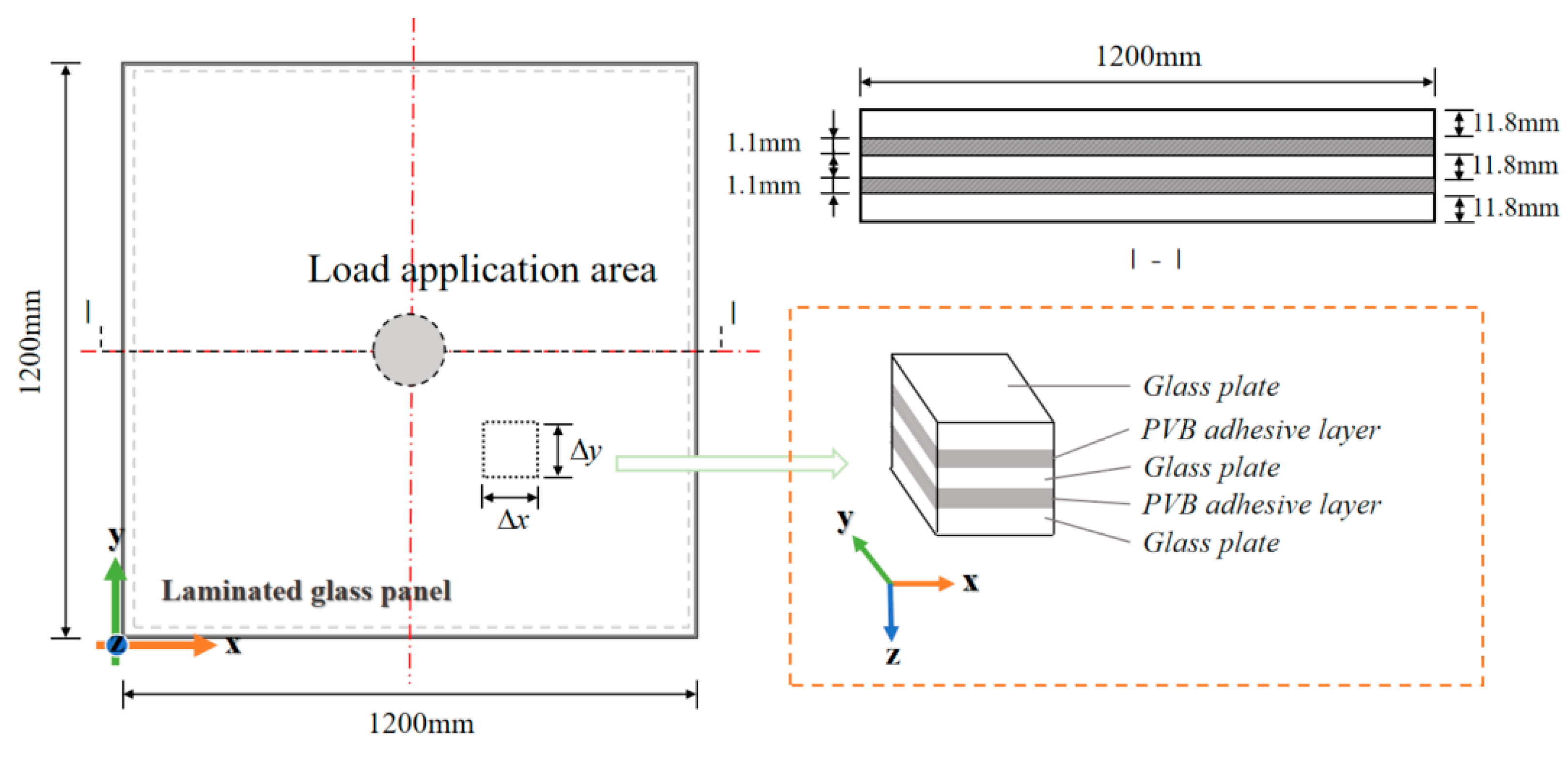
To investigate the bending behavior of different layers of LG under out-of-plane loading, we conducted bending experiments on LG samples. All LG samples were custom-made by the manufacturer, and the glass plates used met the requirements of EN 16612 [11]. We prepared three types of LG samples: 1-layer, 2-layer, and 3-layer. Each type was represented by three identical pieces, totaling nine LG samples. The dimensions of all LG samples were 1200 mm in length and width. In the LG samples, the thickness of each glass layer was 11.8 mm, and the thickness of each PVB layer was 1.1 mm. Figure 5 illustrates the geometry and cross-section of the 3-layer LG sample. Table 4 details the parameters of all of the samples. In the table, 3L-a to 3L-c, 2L-a to 2L-c, and 1L-a to 1L-c denote the three samples of the respective 3-layer, 2-layer, and 1-layer LG.
2.2.2. Displacement Measurement Technology (DIC Technology)
Digital image correlation (DIC) is a non-contact optical method that analyzes digital images of an object’s surface before and after deformation to capture deformation data. This technique typically involves a camera, image analysis software, (Software name: Match ID 2019; version: 19.2.0.0) and markers or speckles that create identifiable surface patterns. The DIC system’s displacement resolution can reach sub-pixel levels, such as 0.01 pixels [37]. Unlike traditional methods that measure strain at discrete points, DIC provides a full-field view of the displacement distribution. The precision of DIC technology is exceedingly high, often within micrometer accuracy.
2.2.3. Test Setup
Figure 6a displays the experimental setup for the LG bending test under out-of-plane loading. The LG was placed on a square steel frame to achieve simple support along its four edges. The geometry of the load application area was a circular section with a radius of 100 mm to simulate the footprints or wheel marks on floor glass in practical applications. This load application area was located at the center of the LG’s upper surface. The loading device was a 3000 kN electric servo-hydraulic press. The experiment employed a displacement-controlled loading at a rate of 2 mm/min. After every 2 mm increment of loading, a 10 s pause was observed to allow for strain measurement collection.
Strain measurements were taken using three-direction strain gauges, with the arrangement of the gauges depicted in Figure 6. A strain reading was recorded after every 2 mm of loading, during the 10 s pause.
Displacement monitoring during the deformation process of the LG was conducted using DIC technology. Speckles were applied to the outer surface of the lower side of the laminated glass to facilitate this monitoring. The measurement area covered only a quarter of the plate surface to exploit symmetry in determining the displacement field of the entire plate. The camera was positioned beneath the glass plate as shown in Figure 6a, and photographs of the DIC measurement area were taken at 0.1 s intervals. The camera specifications are listed in Table 2. Displacement tracking continued even during the loading pauses.
3. Results and Discussion
3.1. Destruction Mode of PVB LG
Figure 7 illustrates the initial condition of the laminated glass and the morphology at the moment of the first failure. Throughout the loading process, two distinct failures are observed. Prior to the first failure, the glass plate uniformly deforms downward under the displacement load. Upon reaching the ultimate load, a sharp “Bang” is heard, signaling the first failure event. At this juncture, the middle and top glass layers remain intact, while the bottom layer shatters into numerous small fragments, creating a network-like pattern. Supported by the unbroken top and middle layers and the adhesive layer’s bonding effect, the glass plate still maintains its flatness, with minimal debris falling off (0–3 pieces).
After the initial failure, the displacement loading proceeds. When the second ultimate load is achieved, another “Bang” indicates the second failure. This time, the top and middle glass layers break almost simultaneously, exhibiting a spider web-like pattern of damage on the top layer. The center of the plate sags significantly, compromising its complete flatness, yet the overall integrity of the glass plate is preserved by the adhesive layer. Figure 8 compares the morphological differences between the two failures. Notably, both instantaneous failures occur during displacement loading—not during the pauses—hence, no crack development takes place while the displacement is maintained.
3.2. In-Plane Distribution of Deflection and Maximum Principal Strain
Traditional out-of-plane bending tests on glass require the use of displacement meters to measure displacement. However, displacement meters can only be placed at a few strategic points, making it challenging to capture a continuous displacement distribution. In this study, we employ DIC binocular vision technology and high-resolution cameras to photograph the speckles in the monitoring area at high frequencies. Utilizing the principle of binocular vision, the displacement field is determined by analyzing changes in the speckle patterns. Figure 9 depicts the displacement distribution changes of samples 3L-a to 3L-c during the loading sequence, with Pu1 representing the ultimate load. Spatially, the displacement contours are nearly circular at the centroid and transition to a rounded square shape near the edges to conform to the boundary support conditions. Over time, the magnitude of central deflection increases, with the lines of equal displacement gradually expanding outward, while the spacing between them decreases as the loading progresses.
Figure 10 presents the distribution of the maximum principal strain for sample 3L-a, measured immediately before failure. The figure indicates that the maximum principal strain values are higher closer to the plate’s center, with the strain direction radiating outward from the center.
From the analysis of displacement and strain distributions, both exhibit similar patterns, with the maximum values occurring near the plate’s center. Consequently, in engineering design calculations for four-sided simply supported PVB laminated glass under symmetric lateral loads, displacement and strain verification should focus on the plate’s center. According to classical thin plate bending theory, the maximum compressive or tensile stress in anti-symmetric bending of thin plates is found on the plate’s top and bottom surfaces, with equal magnitudes. Furthermore, like concrete, silicate glass displays significantly higher compressive strength compared to tensile strength. Therefore, verifying stress and strain on the tensile surface becomes more critical. In summary, for PVB laminated glass under anti-symmetric bending, design calculations for deflection, stress, and strain need only consider the tensile surface at the plate’s center.
3.3. The Influence of the Number of Layers of Glass on Ultimate Load
To evaluate the effect of the number of glass layers on the mechanical response, bending experiments were conducted on one-layer, two-layer, and three-layer glass plates under four-sided simple support conditions. Figure 11 depicts the load-deflection relationship for PVB LG with varying numbers of layers. As illustrated in the figure, the central deflection increases approximately linearly with the increasing load, aligning with the findings of Wang et al. [38].
Figure 12a presents a comparison of the ultimate load-bearing capacities of PVB LG with different layer counts. The data indicate that the average ultimate load-bearing capacities for three-layer, two-layer, and single-layer glass plates are 37.8 kN, 36 kN, and 24.7 kN, respectively, corresponding to a ratio of 1:0.95:0.65. The ultimate load capacity of the two-layer PVB LG is significantly enhanced compared to that of the single-layer glass plate, showing an increase of 45.7%. However, the three-layer PVB LG exhibits only a 5% increase in ultimate load capacity relative to the two-layer PVB LG, despite a 50% increase in thickness. Evidently, from an ultimate load-bearing capacity perspective, utilizing two-layer PVB LG is more cost-effective than three-layer PVB LG in construction projects.
By dividing the ultimate load-bearing capacity of PVB LG (Nu) by the total thickness of the glass (t), the ultimate load capacity per unit thickness is obtained. Figure 13 shows the relationship between ultimate load capacity per unit thickness and the number of glass layers (n). It is evident from the figure that a smaller number of layers results in a higher ultimate load capacity per unit thickness. This finding is in agreement with the theoretical research of Cong [39]. Therefore, unless specific requirements dictate otherwise, it is recommended to select two-layer PVB LG for economic considerations.
3.4. The Influence of the Number of Layers of Glass on Stiffness
Figure 12b compares the stiffness of PVB LG with different numbers of layers. The stiffness , represented as the average slope of the load–deflection curve from Figure 11, increases with the number of layers. The average bending stiffness values for three-layer, two-layer, and single-layer glass plates are 2.77 kN/mm, 1.71 kN/mm, and 1.21 kN/mm, respectively, with a ratio of 1:0.62:0.44. As depicted in Figure 14, the stiffness of LG increases nonlinearly with the number of glass layers, a trend that deviates from expected outcomes. To understand the cause, the bending calculation theory for PVB LG must be considered.
Typically, three assumptions are made when calculating the bending of PVB laminated glass: (a) treating the glass as a simple stack, completely ignoring the PVB and only considering the normal compression between glass layers; (b) assuming the PVB’s elastic modulus is sufficiently high, treating each glass layer as a single unit subject to deformation; (c) the PVB is soft but has adequate bonding strength to participate in deformation coordination. In reality, laminated glass is most likely in the third state, a hybrid of the first two conditions [39]. These three states are illustrated in Figure 15.
If the PVB’s presence is completely disregarded, as portrayed in Figure 15a, the complete calculation method is provided in Chapter 9 of JGJ 113-2015 [10]. For n-layer PVB LG with equal thickness, the deflection calculation is formulated into the following functions:
Among them: is the elastic modulus of glass (MPa); is load (MPa); is Poisson’s ratio for glass (MPa); is center deflection (mm); is thickness of single-layer glass (mm); is flexural rigidity for classical theory (Nmm); is the effective thickness (mm); is the edge length of the board (mm).
According to Formulas (3)–(5), we can deduce that
So,
where
Since the geometric dimensions and material parameters of LG are determined, k is a constant. So formula (7) indicates a linear relationship between and when PVB is excluded. Therefore, the observed nonlinear increase in PVB LG stiffness can be attributed to the influence of PVB as the number of glass layers increases. If an engineering structure requires tight control over deformation, selecting PVB LG with more layers is necessary.
3.5. Selection of PVB Modulus for the Calculation of PVB LG
In studying the selection of the elastic modulus of PVB for the bending calculation of laminated glass, it is essential to first understand the deformation behavior of PVB LG. Currently, the most widely accepted theory for the deformation of PVB LG is that the PVB is soft yet possesses adequate bonding strength. This ensures that the PVB does not separate from the glass, allowing for a compatible deformation relationship between the two materials [36], as illustrated in Figure 15c.
The glass plate is treated as a standard thin plate, with its maximum strain occurring at the top and bottom surfaces. In this scenario, PVB serves as a mediator to coordinate the deformation of the glass plate, experiencing maximum strain at its interface with the glass. Under the premise that PVB remains bonded to the glass, the strain at their interface is identical. Given that the strain on the outer surfaces of the glass in antisymmetric bending is assumed to be the same, the strain recorded on the exterior of the glass in the experiments described in Section 2.2 is approximately equal to the strain at the interface between the glass and PVB. Referring to the strain distribution shown in Figure 10, the observed maximum strain (1.6 × 10⁻³) is significantly less than 0.6, which indicates that the PVB is within the initial, elastic stage depicted in Figure 4.
Accordingly, under loading conditions, the PVB in laminated glass remains within the elastic range. For theoretical calculations, the elastic modulus of PVB is taken from the linear portion of the stress–strain curve at a tensile rate of 10 mm/min, which is = 1.34 MPa. Given that the values of Poisson’s ratio from various national standards and academic research are comparable, these values are considered consistent. In this study, Poisson’s ratio is set to 0.5, fulfilling the criteria of both EN 16612 [11] and JGJ 113-2015 [12].
4. Conclusions
In addressing the complex mechanical behavior of PVB laminated glass, this study conducted loading tests. Observations were made of the load–displacement curve, as well as the displacement and strain distribution during loading. The study analyzed variations in stiffness and ultimate bearing capacity with respect to the number of glass layers. Additionally, the mechanical properties of PVB were examined to assess their constitutive characteristics. The findings are summarized as follows:
- The load–displacement curve remains approximately linear prior to damage in the LG. Displacement manifests a circular distribution within the plane, with the first principal strain value increasing towards the center of the plate. The direction of the first principal strain radiates from the center of the plate.
- The average ultimate load capacity for three-layer, two-layer, and single-layer PVB laminated glass is 37.8 kN, 36 kN, and 24.7 kN, respectively, corresponding to a ratio of 1:0.95:0.65. The bending stiffness values for the same are 2.77 kN/mm, 1.71 kN/mm, and 1.21 kN/mm, respectively, with a ratio of 1:0.62:0.44. The ultimate bearing capacity of PVB LG increases with the number of layers; however, this increase diminishes with additional layers, leading to material waste. For economic efficiency, it is advisable to utilize LG with fewer layers in practical applications. The stiffness of LG increases nonlinearly with the addition of layers, an effect attributable to the characteristics of PVB. For engineering structures with strict deformation limits, selecting PVB LG with more layers is necessary.
- The mechanical property testing presented in this paper reveals that the constitutive model of PVB laminate transitions from tensile deformation to fracture with a bilinear relationship to strain rate. Elastic modulus is found to be lower at reduced strain rates. Linearity is maintained when axial strain is below 0.6. Beyond an axial strain of 1.6, the elastic modulus significantly increases, the differential being more than tenfold. Considering the overall bending deformation of laminated glass plates, the maximum principal strain on the surface is two orders of magnitude less than 0.6. Therefore, this study concludes that the PVB layer involved in deformation coordination is within the low strain rate stage. For calculating the out-of-plane bending of laminated glass, it may be treated as a material with small-scale linear elasticity. The recommended elastic modulus is 1.34 MPa.
It should be noted that these conclusions are derived from quasi-static experiments and do not apply to the mechanical response under high-speed impact loading. Furthermore, these conclusions pertain solely to PVB LG under four-sided simple support conditions, necessitating further research to ascertain their relevance to point-supported LG.
Author Contributions
Conceptualization, H.L.; Methodology, L.Y., H.L., N.Z. and W.S.; Validation, R.H.; Writing—original draft, L.Y.; Writing—review and editing, N.Z., W.S. and R.H.; Visualization, L.Y.; Supervision, H.L. and W.S.; Project administration, H.L. and N.Z. All authors have read and agreed to the published version of the manuscript.
Funding
This research was funded by the National Natural Science Foundation of China (No. 52208207), the Natural Science Basic Research Plan in Shaanxi Province of China (No. 2022JQ-475).
Data Availability Statement
The raw data supporting the conclusions of this article will be made available by the authors on request.
Conflicts of Interest
The authors declare no conflicts of interest.
References
- Ivanov, I.V. Analysis, modelling, and optimization of laminated glasses as plane beam. Int. J. Solids Struct. 2006, 43, 6887–6907. [Google Scholar] [CrossRef]
- Vallabhan, C.G.; Minor, J.E.; Nagalla, S.R. Stresses in layered glass units and monolithic glass plates. J. Struct. Eng. 1987, 113, 36–43. [Google Scholar] [CrossRef]
- Bennison, S.J.; Jagota, A.; Smith, C.A. Fracture of glass/poly (vinyl_butyral)_laminates. in biaxial flexure. Am. Ceram. Soc. 1999, 82, 1762–1770. [Google Scholar] [CrossRef]
- Nawar, M.; Salim, H.; Lafta, M.; Elshihy, A. Quasi-Static Performance of Interlayer Systems for Laminated Glass. J. Mater. Civ. Eng. 2015, 28, 04015084. [Google Scholar] [CrossRef]
- Edel, M.T. The Effect of Temperature on the Bending of laminated Glass Beams. Ph.D. Thesis, Texas A&M University, College Station, TX, USA, 1997. [Google Scholar]
- Hooper, J.A. On the bending of architectural laminated glass. Int. J. Mech. Sci. 1973, 15, 309–323. [Google Scholar] [CrossRef]
- Aşık, M.Z.; Tezcan, S. A mathematical model for the behavior of laminated glass beams. Comput. Struct. 2005, 83, 1742–1753. [Google Scholar] [CrossRef]
- Aşık, M.Z. Laminated glass plates: Revealing of nonlinear behavior. Comput. Struct. 2003, 81, 2659–2671. [Google Scholar] [CrossRef]
- Vallabhan, C.G.; Wang, B.Y.-T.; Chou, G.D.; Minor, J.E. Thin glass plates on elastic supports. J. Struct. Eng. 1985, 111, 2416–2426. [Google Scholar] [CrossRef]
- AS 1288-2006; Glass in Buildings-Selection and Installation. Australian Standard: Sydney, Australia, 2006.
- Siebert, G. Comparison of IGU-design according to German and European Standards. ce/papers 2018, 2, 81–92. [Google Scholar] [CrossRef]
- JGJ 113-2015; Technical Specification for Application of Architectural Glass. Human Resources and Social Security Ministry of the People’s Republic of China: Beijing, China, 2015.
- ASTME1300-16; Standard Practice for Determining Load Resistance of Glass in Buildings. ASTM International: West Conshohocken, PA, USA, 2007.
- Behr, R.A. Design of architectural glazing to resist earthquakes. J. Archit. Eng. 2006, 12, 122–128. [Google Scholar] [CrossRef]
- Kaiser, N.D.; Behr, R.A.; Minor, J.E.; Dharani, L.R.; Ji, F.; Kremer, P.A. Impact resistance of laminated glass using “sacrificial ply” design concept. J. Archit. Eng. 2000, 6, 24–34. [Google Scholar] [CrossRef]
- Weggel, D.C.; Zapata, B.J. Laminated glass curtain walls and laminated glass lites subjected to low-level blast loading. J. Struct. Eng. 2008, 134, 466–477. [Google Scholar] [CrossRef]
- Saxe, T.J.; Behr, R.A.; Minor, J.E.; Kremer, P.A.; Dharani, L.R. Effects of missile size and glass type on impact resistance of “sacrificial ply” laminated glass. J. Archit. Eng. 2002, 8, 24–39. [Google Scholar] [CrossRef]
- Biolzi, L.; Simoncelli, M. Overall response of 2-ply laminated glass plates under out-of-plane loading. Eng. Struct. 2022, 256, 113967. [Google Scholar] [CrossRef]
- Galić, M.; Grozdanić, G.; Divić, V.; Marović, P. Parametric Analyses of the Influence of Temperature, Load Duration, and Interlayer Thickness on a Laminated Glass Structure Exposed to Out-of-Plane Loading. Crystals 2022, 12, 838. [Google Scholar] [CrossRef]
- Ali, H.; Gianni, C.R. A simple model for inflexed multi-layered laminated glass beams based on refined zig-zag theory. J. Appl. Mech. -Trans. Asme 2022, 90, 011002. [Google Scholar]
- Jaśkowiec, J.; Pluciński, P.; Stankiewicz, A.; Cichoń, C. Three-dimensional modelling of laminated glass bending on two-dimensional in-plane mesh. Compos. Part B 2017, 120, 63–82. [Google Scholar] [CrossRef]
- Vedrtnam, A.; Bedon, C.; Youssef, M.A.; Chaturvedi, S. Effect of non-uniform temperature exposure on the out-of-plane bending performance of ordinary laminated glass plate. Compos. Struct. 2021, 275, 114517. [Google Scholar] [CrossRef]
- Yongjiu, S.; Ying, M.; Yuanqing, W. Finite element analysis of bending performance of point-supported laminated glass plate. Archit. Sci. 2009, 25, 1–3+8. [Google Scholar]
- Wen, W.; Lipu, R.; Jiading, P. Study on the deformation performance of point-supported laminated glass panels. Sichuan Archit. 2008, 5, 139–140. [Google Scholar]
- Galuppi, L.; Royer-Carfagni, G. Enhanced effective thickness of multi-layered laminated glass. Compos. Part B Eng. 2014, 64, 202–213. [Google Scholar] [CrossRef]
- Zhang, X.; Yang, J.; Meng, Z. Mechanical behaviour of frame-supported insulating glass during cold bending. J. Build. Eng. 2023, 65, 105722. [Google Scholar] [CrossRef]
- Vedrtnam, A.; Pawar, J.S. Experimental and simulation studies on bending behavior of laminated glass with polyvinyl butyral and ethyl vinyl acetate inter-layers of different critical thicknesses. J. Sandw. Struct. Mater. 2019, 21, 2219–2238. [Google Scholar] [CrossRef]
- Mohagheghian, I.; Wang, Y.; Jiang, L.; Zhang, X.; Guo, X.; Yan, Y.; Kinloch, A.J.; Dear, J.P. Quasi-static bending and low velocity impact performance of monolithic and laminated glass windows employing chemically strengthened glass. Eur. J. Mech./A Solids 2017, 63, 165–186. [Google Scholar] [CrossRef]
- Huang, X.; Liu, G.; Liu, Q.; Bennison, S.J. Influence of Interlayers on the Flexural Performance of Four-Side Supported Laminated Glass at Room Temperature. Adv. Struct. Eng. 2015, 18, 33–43. [Google Scholar] [CrossRef]
- Ferry, J.D. Viscoelastic Properties of Polymers; John Wiley & Sons: Hoboken, NJ, USA, 1980. [Google Scholar]
- Du Bois, P.A.; Kolling, S.; Fassnacht, W. Modelling of safety glass for crash simulation. Comput. Mater. Sci. 2003, 28, 675–683. [Google Scholar] [CrossRef]
- Du Bois, P.A.; Kolling, S.; Koesters, M.; Frank, T. Material behaviour of polymers under impact loading. Int. J. Impact Eng. 2006, 32, 725–740. [Google Scholar] [CrossRef]
- ISO 3537; Road Vehicles-Safety Glazing Materials-Mechanical Tests. ISO: Geneva, Switzerland, 1993.
- Kluppel, M.; Schramm, J.A. Generalized tube model of rubber elasticity andstress softening of filler reinforced elastomer systems. Macromol. React. Eng. 2000, 9, 742–754. [Google Scholar]
- Xu, J.; Li, Y.; Ge, D.; Liu, B.; Zhu, M. Experimental investigation on constitutive behavior of PVB under impact loading. Int. J. Impact Eng. 2010, 38, 106–114. [Google Scholar] [CrossRef]
- Rong, W.; Chen, S. Research on the properties of PVB at home and abroad. Polym. Bull. 2012, 5, 82–88. [Google Scholar]
- Duan, Q.; Gong, W.; Guo, B.; Wu, L.; Yu, X.; Xie, H. Techniques of speckle fabrication and image processing for high temperature digital image correlation. J. Tsinghua Univ. (Sci. Technol.) 2019, 59, 425–431. [Google Scholar]
- Wang, X.; Zhang, Q.; Tao, Z.; Chen, J.; Chen, J. Theoretical and experimental study on the load-bearing performance of four-sided simply supported laminated glass. Build. Struct. 2012, 42, 173–175. [Google Scholar]
- Cong, D. Study on the bending resistance of point-supported laminated glass 2003. Natl. Conf. Struct. Eng. 2003, 1, 499–504. [Google Scholar]
Figure 1.
Tensile specimen.

Figure 2.
PVB layout for the tensile test.

Figure 3.
Process of PVB specimen stretching.

Figure 4.
Engineering stress–strain relationship of the PVB samples.


Figure 5.
PVB laminated glass specimen.

Figure 6.
Experimental setup.

Figure 7.
Failure forms of LG before and after the first failure event.

Figure 8.
Failure forms of LG after two successive failures.

Figure 9.
Load–lateral displacement curve of three-layer laminated glass center.

Figure 10.
Distribution of maximum principal stress on the surface of 3L-a.

Figure 11.
Load–central deflection curve of LG of different layers.

Figure 12.
Ultimate load, stiffness of LG of different layers.

Figure 13.
The ultimate bearing capacity per unit thickness–number of layers curve.

Figure 14.
Stiffness–number of layers curve.

Figure 15.
Three working states of PVB LG.


Table 1.
Parameters of the PVB sample.
| No. | Symbol | Physical Parameter | Size (mm) |
|---|---|---|---|
| 1 | L | Total length | 115 |
| 2 | d | Thickness | 1.1 |
| 3 | b | Small radius | 14 |
| 4 | G0 | Gauge length | 25 |
| 5 | W | End width | 25 |
| 6 | H | Distance between fixtures | 80 |
| 7 | C | Middle section width | 6 |
| 8 | R0 | Middle section length | 33 |
| 9 | R1 | Large radius | 25 |
Table 2.
Camera specifications.
| No. | Parameter | Value |
|---|---|---|
| 1 | Sensor | 1.1″ IMX304 Global shutter CMOS (FRAMOS, Ottawa, ON, Canada) |
| 2 | Resolving power | 4112 (H) × 3008 (V) |
| 3 | Pixel depth | 8 bit |
| 4 | Image data format | Mono8, Mono12, Mono12p |
| 5 | Pixel size | 3.45 μm |
| 6 | Mechanical dimensions (W × H × L) | 44 mm × 29 mm × 86.3 mm |
Table 3.
Experimental results for the mechanical properties of PVB.
| Number | Sample | (mm/min) | (%) | (MPa) | (MPa) | (MPa) |
|---|---|---|---|---|---|---|
| 1 | PVB-001 | 10 | 1.74 | 10.27 | 1.04 | 17.78 |
| 2 | PVB-002 | 10 | 2.03 | 17.37 | 1.43 | 18.42 |
| 3 | PVB-003 | 10 | / | / | / | / |
| 4 | PVB-004 | 10 | 2.16 | 18.82 | 1.47 | 18.32 |
| 5 | PVB-005 | 10 | 1.85 | 13.67 | 1.41 | 16.48 |
| 6 | PVB-006 | 20 | 2.08 | 17.85 | 1.57 | 18.54 |
| 7 | PVB-007 | 20 | 2.06 | 17.32 | 1.51 | 18.65 |
| 8 | PVB-008 | 20 | 2.02 | 17.24 | 1.57 | 18.32 |
| 9 | PVB-009 | 20 | 2.19 | 18.87 | 1.37 | 18.72 |
| 10 | PVB-010 | 20 | 2.19 | 21.98 | 1.70 | 19.67 |
Note: = stretching rate; = ultimate strain; = ultimate stress; = first-stage elastic modulus; = third-stage elastic modulus.
Table 4.
Sample-related parameters and experimental results.
| No. | Specimen Label | (kN) | (mm) | (kN/mm) | |
|---|---|---|---|---|---|
| 1 | 3L-a | 3 | 47.8 | 16.4 | 2.91 |
| 2 | 3L-b | 34.2 | 13.5 | 2.53 | |
| 3 | 3L-c | 37.3 | 13.1 | 2.86 | |
| 4 | 2L-a | 2 | 31 | 16.3 | 1.9 |
| 5 | 2L-b | 35 | 21.9 | 1.6 | |
| 6 | 2L-c | 42 | 25.8 | 1.63 | |
| 7 | 1L-a | 1 | 22.1 | 24.6 | 0.9 |
| 8 | 1L-b | 26.5 | 27.9 | 0.95 | |
| 9 | 1L-c | 25.5 | 21.1 | 1.21 |
Note: = ultimate load; = ultimate deflection of plate center; = average slope of load deflection curve; n = number of glass layers.
Disclaimer/Publisher’s Note: The statements, opinions and data contained in all publications are solely those of the individual author(s) and contributor(s) and not of MDPI and/or the editor(s). MDPI and/or the editor(s) disclaim responsibility for any injury to people or property resulting from any ideas, methods, instructions or products referred to in the content. |
© 2024 by the authors. Licensee MDPI, Basel, Switzerland. This article is an open access article distributed under the terms and conditions of the Creative Commons Attribution (CC BY) license (https://creativecommons.org/licenses/by/4.0/).
Share and Cite
MDPI and ACS Style
Yun, L.; Li, H.; Zhang, N.; Shi, W.; Haider, R. Research on Out-of-Plane Bending Test of PVB Laminated Glass Plate with Different Number of Layers. Appl. Sci. 2024, 14, 3416. https://doi.org/10.3390/app14083416
AMA Style
Yun L, Li H, Zhang N, Shi W, Haider R. Research on Out-of-Plane Bending Test of PVB Laminated Glass Plate with Different Number of Layers. Applied Sciences. 2024; 14(8):3416. https://doi.org/10.3390/app14083416
Chicago/Turabian StyleYun, Lu, Hui Li, Ning Zhang, Wei Shi, and Rizwan Haider. 2024. "Research on Out-of-Plane Bending Test of PVB Laminated Glass Plate with Different Number of Layers" Applied Sciences 14, no. 8: 3416. https://doi.org/10.3390/app14083416
Note that from the first issue of 2016, this journal uses article numbers instead of page numbers. See further details here.