Article

Design of Series-Fed Circularly Polarized Beam-Tilted Antenna for Microwave Power Transmission in UAV Application

1
Department of Electrical and Computer Engineering, Sungkyunkwan University, Suwon 16419, Republic of Korea
2
Power ICT Research Center, Korea Electrotechnology Research Institute, Ansan 15588, Republic of Korea
*
Author to whom correspondence should be addressed.
Appl. Sci. 2024, 14(8), 3490; https://doi.org/10.3390/app14083490
Submission received: 7 March 2024 / Revised: 14 April 2024 / Accepted: 16 April 2024 / Published: 20 April 2024
(This article belongs to the Special Issue Multi-Band/Broadband Antenna Design, Optimization and Measurement)

Abstract

:
In response to the increasing deployment of unmanned aerial vehicles (UAVs) across various sectors, the demand for efficient microwave power transmission (MPT) systems for UAVs has become paramount. This study introduces series-fed circularly polarized (CP) and passively beam-tilted patch array antennas designed to enhance MPT in UAV applications, with the intention of addressing the needs related to extending flight times and improving operational efficiency. The radiating element of the proposed antennas employs the conventional model of the patch with truncated corners for CP operation, with transmission line lengths optimized for beam tilt to ensure precise energy transfer. Additionally, an open stub is integrated into the broadside series-fed antenna to improve impedance matching, which is crucial for maintaining signal integrity. The proposed design achieves right-hand circular polarization (RHCP) with an axial ratio (AR) below 3 dB across the operating band, indicative of its effectiveness in diverse UAV operational contexts. Prototypes of each proposed antenna were fabricated and measured according to the beam tilting angle. The measured RHCP realized gains of the proposed antennas are 14.59, 13.09, 13.07, and 10.71 dBic at the tilted angles of 0°, 15°, 30°, and 45°, respectively, at 5.84 GHz.

1. Introduction

Unmanned aerial vehicles (UAVs), such as drones and aircraft, have become widely employed for applications such as agriculture [1,2], search and rescue missions [3], monitoring and data collection [4], disaster monitoring [5], and more. With the development of advanced technologies, UAVs are now equipped with additional electronics, such as cameras and sensors, which are typically powered by the UAV’s battery. As a result, UAV-based systems face technical limitations in long-term flights due to the limited energy of their batteries [6]. To increase the available flight time and mission duration by wirelessly recharging the batteries while the UAV is in flight, long-distance microwave power transmission (MPT) technology has been applied and developed [7,8,9,10,11]. In the 1960s, the MPT experiment on a flying helicopter was conducted by W.C. Brown and his team for the first time, using a rectenna array consisting of half-wave dipoles spaced a half wavelength apart at 2.45 GHz [8]. In the 1980s, SHARP Canada developed a rectenna array consisting of linear dipoles in a thin-film plastic sheet at 2.45 GHz, which was intended for use in aircraft [9]. Some previous studies [10,11] have explored the use of rectennas with low-profile and lightweight microstrip antennas to extend limited payload and improve the aerodynamic behavior of UAVs. In [10], a microstrip dipole array antenna in X-band was designed for use with a helium gas vehicle, and a 4 × 2 microstrip patch antenna with a gain of 13.4 dBi operating at 35 GHz for UAV [11] were designed for use as rectennas. In addition, a 1 × 4 series-fed patch array antenna operating at 28 GHz was combined with a power divider, resulting in a 16-patch array antenna with a gain of 18.71 dBi, which was designed as a drone’s rectenna [12]. Furthermore, a 16 × 16 transmitting array antenna operating in CP at 5.74 GHz formed a flat-top-beam, and a 4 × 4 receiving microstrip patch array was formed into a single rectenna for the drone [13].
In the MPT systems, integrating UAV trajectory with directional antenna orientation optimization has emerged as a significant innovation. This approach considerably enhances energy harvesting in UAV-enabled networks and mitigates long-distance radio frequency (RF) signal loss, thus significantly improving wireless power transfer (WPT) efficiency. The innovative mobile wireless-powered communication network (WPCN), employing an optimal transmission policy and a two-layer algorithm, represents a foundational step in this direction [14]. In [15,16], a substantial enhancement in the efficiency of WPT was elucidated through the synergistic optimization of UAV flight trajectories and the orientation of directional antennas. This optimization not only augments energy harvesting capabilities within UAV-integrated networks but also effectively addresses the critical issue of long-distance radio frequency (RF) signal attenuation.
The essence of minimizing misalignment losses between the transmitter and receiver lies in these advancements. The advent of beam steering (or tilting) antennas represents a critical solution to these losses, with the technology being adaptable through both mechanical and electronic implementations. Mechanical beam steering requires physical adjustment of the antenna, necessitating a complex installation framework that consequently increases the UAV’s payload and power demands. On the other hand, electronic beam steering techniques, which modify the main beam’s direction by altering the phase of each antenna element or subarray, offer a more streamlined and low-profile solution. This electronic modulation is facilitated by digital phase shifters [17], varactor diodes [18], and double-pole double-throw (DPDT) switches [19], enabling rapid and efficient adjustments that are crucial for active beam steering. However, implementing such antennas, especially receive antennas with high array circuitry, may increase the overall system cost and require additional power for the operation of the phase shifter, which could negatively affect the UAV’s limited battery life.
Electronically passive beam steering, in contrast, is less expensive, offers a lower profile, and has a simpler design than its active counterpart, eliminating the need for additional electronics. In [20], the main lobe is steered from 60° to 90° without additional electronics, using a parallel feeding network to minimize sidelobe levels. The design in [21] features index-modulated tilted-beam microstrip antennas with a 50° tilt and a 33.8% bandwidth enhancement. In [22], a symmetrically 45° dual-polarized rectenna array is introduced for wide-coverage MPT, incorporating differentially-feeding networks to achieve low insertion loss. A beam tilted at a 37° angle using phase adjustments in the transmission line is reported in [23], facilitating passive beam tilting while maintaining a low profile. Additionally, the series-fed antenna can implement electrically passive fixed-beam tilting while maintaining a low profile. [24] describes a series-fed microstrip array antenna with a 30-degree tilt, merging the radiation patterns of a patch and two monopoles. In [25], a broadband fixed-beam leaky-wave antenna (LWA) achieves stable beam angles of 0°, 25°, and −25° with gains up to 15.7 dBi over a 43% bandwidth. In [26], a series-fed dual-port array antenna is presented, achieving up to 44.6% efficiency and output power across a 90° angle range. Finally, [27] details a compact frequency scanning antenna array that offers enhanced sector scanning from 73° to 132° and gains between 15.5 and 17 dBi, suitable for radar and communication technologies. In addition to reducing beam misalignment losses, circularly polarized (CP) antennas also help to mitigate polarization losses between the transmitting and receiving antennas [28], enhancing overall system performance.
In this paper, we propose a series-fed and beam-tilted CP antenna design intended for efficient wireless power reception on airborne UAVs. The primary focus lies in tilting the main lobe of the proposed antenna, a feature influenced by both the curvature of the UAV and the attachment location of the receiving antennas. This beam tilt of the main lobe facilitates easy alignment between the main lobe direction of the receiving array antenna and that of the ground-based transmitting array antenna. The radiating element of the proposed series-fed antennas is a patch with truncated corners, which enables CP radiation. U-shaped bend transmission lines are employed to connect and feed each radiating patch in a series. The length of the U-shaped bend transmission line, which controls the phase difference between the adjacent radiating patches, determines the beam-tilted angle of the proposed antennas. A coaxial connector feeds the antennas and does not require a complex feeding network. Broadside and beam-tilted antennas with tilt angles of 15°, 30°, and 45° were each designed, fabricated, and measured. The center frequency and highest gain frequency of the transmitting array antenna are 5.84 GHz. Therefore, the proposed receiving array antennas are also designed to operate at a central frequency of 5.84 GHz. Simulations were performed using CST Studio Suite.
The organization of the paper is as follows: Section 2 provides a description of the unit cell and the proposed antennas, as well as introducing an impedance-matching network and tilted beam. Section 3 compares the measured results of the proposed antennas with the simulated results. Finally, Section 4 presents the conclusions of this study.

2. Antenna Design

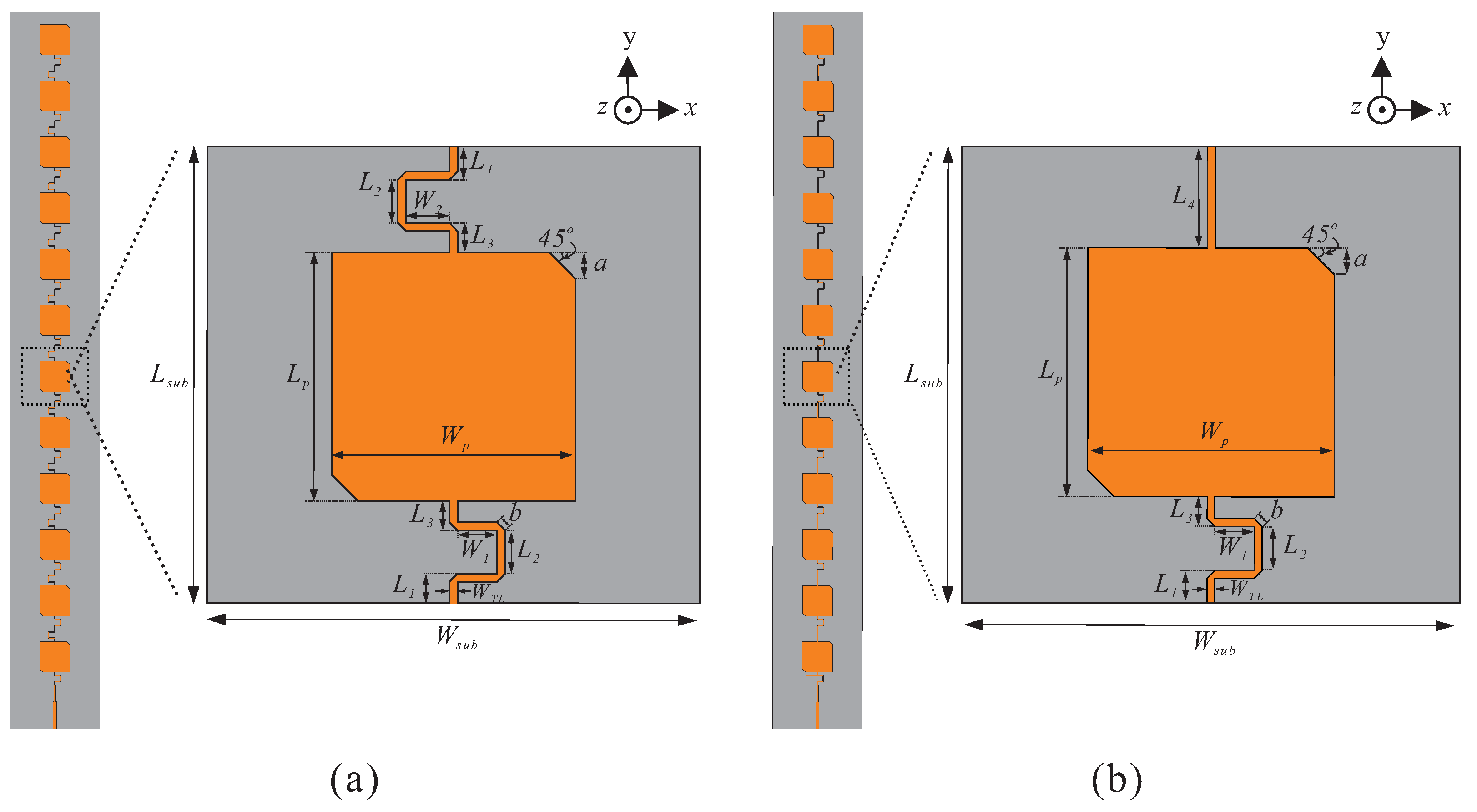
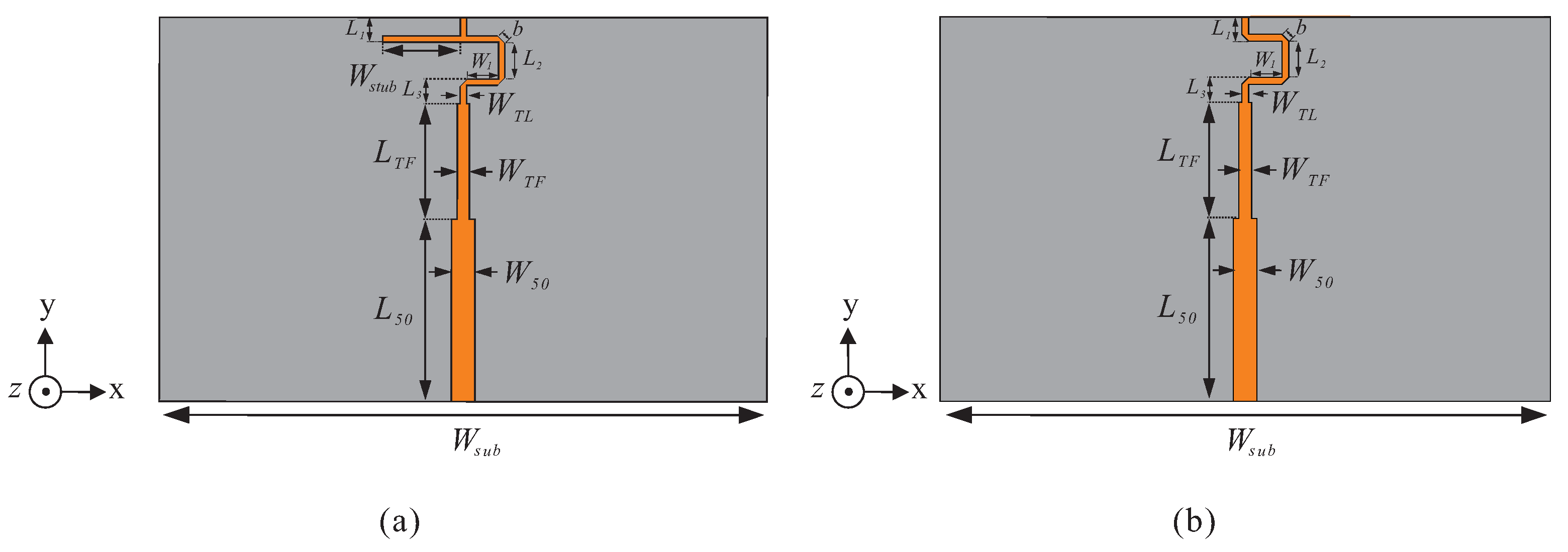
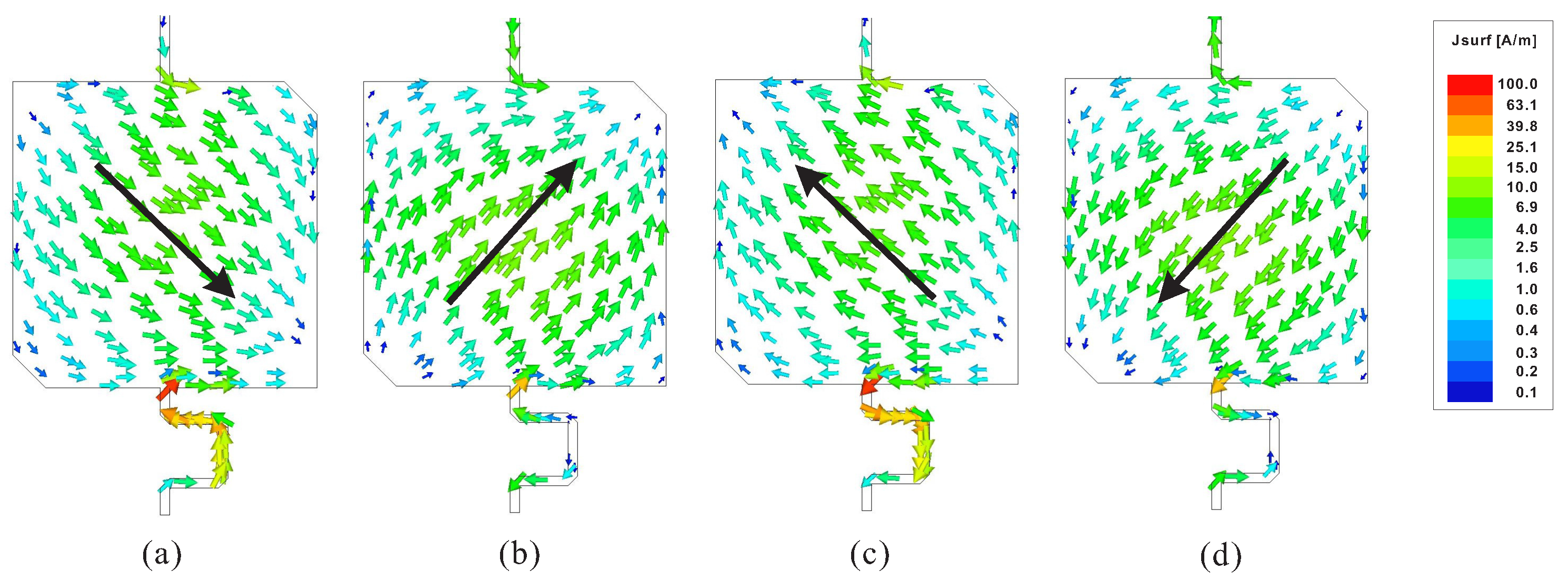
2.1. The Design of Unit Cell and Proposed Series-Fed Antenna

Figure 1 shows the configurations of the proposed series-fed antennas. The proposed antennas are designed on a Taconic RF-35 dielectric substrate, which at 1.9 GHz exhibits a relative permittivity of 3.5 and a loss tangent of 0.0018, with a thickness of 0.76 mm. The design positions the radiating elements on the substrate’s top side and a ground plane on the bottom side. As depicted in Figure 1, each unit cell within the array includes a patch with truncated corners to facilitate CP radiation towards the +z–direction. These patches are interconnected through transmission lines, ensuring series feeding across the 12-unit cells comprising the antenna array. The characteristic impedance of these transmission lines is maintained at approximately 100 Ω , which reduces radiation loss that occurs in the transmission lines [29].
In the beam-tilted antenna configuration (Figure 1a), the transmission lines below and above the patch in the unit cell include U-shaped bends in opposite directions. The U-shaped bends in opposite directions are proposed to reduce the coupling between parallel microstrip lines in a series-fed array arrangement. In contrast, the unit cell of the broadside antenna, described in Figure 1b, contains a U-shaped bend transmission line below the patch and a straight upper transmission line. The U-shaped bend transmission line is chamfered at the corners to reduce losses, enhancing the overall antenna efficiency, as shown in Figure 1a,b.
The length of the upper U-shaped bend in each unit cell determines a progressive phase value between each radiating patch that is required to implement the beam tilting. The proposed series-fed array antennas, comprising 12 series-connected unit cells, incorporate patches with truncated corners and transmission lines that link these patches, supported by a ground plane underneath. To maintain a compact size and avoid grating lobes, the distance between each patch is fixed at L s u b = 25 mm (0.487 λ 0 , where λ 0 is the free space wavelength at 5.84 GHz). Table 1 shows the detailed values of design parameters, all of which have been optimized. Simulations were carried out using CST Studio Suite.
Figure 2 presents the simulation results of the reflection coefficient, axial ratio (AR), and RHCP realized gain patterns of the proposed antenna’s radiating patch. As shown in Figure 2a, the reflection coefficient is below −10 dB across the frequency band of 5.77–5.88 GHz. This band also corresponds to the antenna’s 3-dB AR bandwidth, as indicated in Figure 2b, ranging from 5.81–5.85 GHz. Figure 2c,d show the radiation patterns of the patch as realized RHCP gain in the ϕ = 90 plane and ϕ = 0 plane at 5.84 GHz, respectively. The patch has directional characteristics and maximum radiation in the +z-direction with a gain of 6.2 dBic, and half-power beamwidths (HPBW) of 90° and 89° in the ϕ = 90 and ϕ = 0 planes, respectively. Figure 3 shows the simulated surface current distributions of the radiating patch of the unit cell observed in the proposed +z-direction to confirm the RHCP radiation at different times t = 0, T / 4 , T / 2 , and 3 T / 4 , where T is the oscillation period at 5.84 GHz. The direction of current distribution rotates counterclockwise with increasing time, indicating RHCP radiation in the +z-direction.
Figure 4 and Figure 5 shows parameter study of the unit cell for varying L p and a. Figure 4a reveals that increasing the patch length L p from 13.5 mm to 13.9 mm causes the resonance frequency to lower, refining the resonance quality as demonstrated by a deeper and sharper reflection coefficient. Meanwhile, Figure 4b indicates a marginal degradation in circular polarization purity with increasing L p . The chosen patch length L p of 13.7 mm achieves an optimal trade-off, resulting in both a low reflection coefficient and a good axial ratio, signifying a well-optimized antenna for circular polarization. Figure 5a shows how increased truncation shifts the resonant frequency lower and alters the reflection coefficient. Figure 5b shows the axial ratio’s sensitivity to a, with the optimal circular polarization observed at a = 1.39 mm. The chosen truncated corner length a of 1.39 mm is an optimal trade-off for achieving robust resonance and high-quality circular polarization.
A F L i n e a r = n = 1 N e j ( n 1 ) ( k d cos θ + β )
A r r a y P a t t e r n = E P × A F
Equation (1) represents the array factor of a linear array ( A F L i n e a r ), where k d c o s θ + β signifies the phase difference of each element, with N being the element number of the linear array, k the wave number, d the distance between elements, θ the angle with respect to the array axis, and β the progressive phase shift applied to the elements [30]. N is 12, and the distance between antenna elements is kept at 25 mm ( 0.487 λ 0 , where λ 0 is the free space wavelength at 5.84 GHz) to prevent grating lobes and maintain a compact array. At 5.84 GHz, to achieve broadside radiation and beam tilting angles of 15 , 30 , and 45 with respect to the array axis, the β values are calculated in ascending order of beam tilting angles as 0 , 45.35 , 87.61 , and 123.89 .
Equation (2) represents the radiation pattern formula for an array antenna, where the radiation pattern of the array is calculated as the product of the Element Pattern (EP) of a single antenna and the array factor. Figure 6 shows the normalized radiation pattern of the proposed linear array series-fed array antenna, calculated by multiplying the array factor from Equation (1) with the element pattern from Figure 2c. As the phase difference from 0 increases, the beam tilting angle of the normalized radiation pattern also increases, reaching maximum magnitude at 15 , 30 , and 45 .
Figure 7 shows simulated results for different W 2 in the U-shaped bend transmission line. Figure 7a shows the phase of the transmission coefficient of the unit cell according to the change in W 2 . As W 2 increases 0 mm, 1.2 mm, 2.1 mm, and 2.9 mm, the phase of the transmission coefficient of the unit cell decreases 0 , 45.8 , 92.5 and 127 , which are close to calculated β in Equation (1). The proposed antennas achieve beam tilting using a progressive phase shift, β in Equation (1), controlled by the phase of the transmission coefficient of the unit cell. Figure 7b shows the RHCP realized gain pattern of the proposed series-fed antennas at 5.84 GHz in the ϕ = 90 plane. When W 2 is 0 mm, 1.2 mm, 2.1 mm, and 2.9 mm in sequence, the direction of the main lobe is formed at θ = 0 , 15 , 30 , and 45 in the ϕ = 90 plane. The RHCP realized gain patterns in Figure 7b are almost similar to the calculated and normalized array pattern in Figure 6. Beam tilting of the proposed antennas is realized by adjusting the length of the serial feeding line, so an individual antenna is implemented for each beam tilting angle.
Figure 7c,d show the simulated reflection coefficients and axial ratios of the series-fed array antennas. The simulated reflection coefficients of broadside series-fed array antenna and 15°, 30° and 45° beam tilt series-fed array antennas at 5.84 GHz are −19.35 dB, −21.8 dB, −35.6 dB and −29.1 dB in sequence. The simulated axial ratios of the series-fed array antennas at 5.84 GHz are 2.35 dB, 2.91 dB, 2.65 dB, and 2.69 dB in the same sequence. The designs of individual array antennas for each beam tilting angle are optimized for the low AR level required to achieve CP at the tilted angle.
Figure 8 shows simulated RHCP realized gain patterns for W 2 values at 5.84 GHz in the ϕ = 90 plane, delineating the performance characteristics of two linear array antennas with a varying number of the proposed antenna’s unit cells. The 1 × 12 series-fed array antennas shown in Figure 8a feature a sharper main lobe with higher gain and lower sidelobe levels compared to the 1 × 6 series-fed array displayed in Figure 8b. As the gain increases, the radiation pattern of the 1 × 12 series-fed array exhibits a narrower beamwidth than the 1 × 6 series-fed array. Specifically, for the largest tilted angle at W 2 = 2.9 mm, the HPBW for the 1 × 12 series-fed array is 16.3 , while the 1 × 6 series-fed array has a HPBW of 26.5 , resulting in a difference of 10.2 .

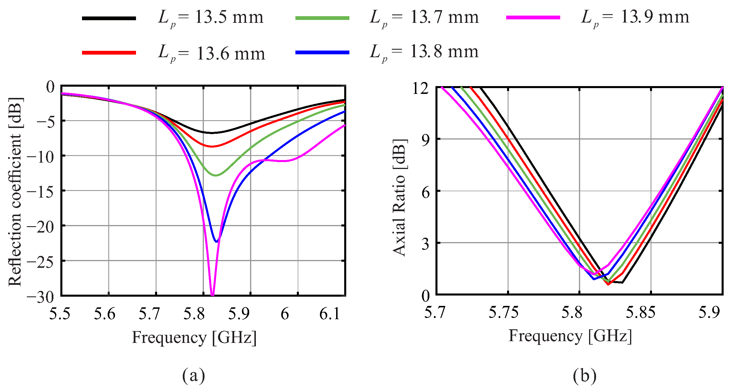
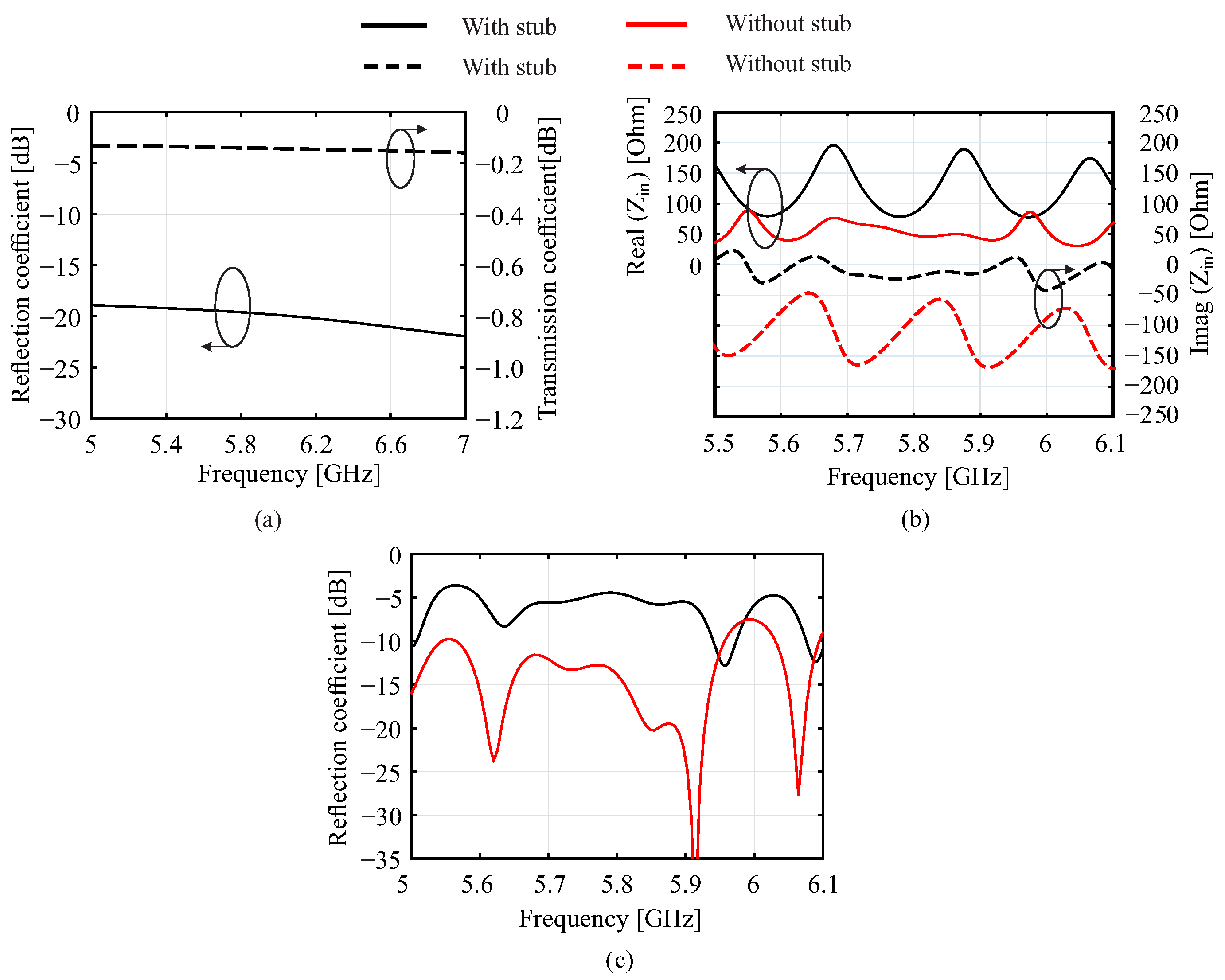
2.2. The Design of the Matching Network of the Proposed Series-Fed Antenna

Figure 9 shows the impedance-matching network configurations of the proposed antennas, including a broadside and beam-tilted antenna design. The feed line at the input port is a 50 Ω microstrip line with L 50 = 12 mm and W 50 = 1.55 mm for connection with the coaxial connector. A quarter wavelength transformer with L T F = 7.6 mm (0.25 λ g , where λ g is the guided wavelength at 5.84 GHz) and W T F = 0.8 mm is inserted to match the impedance between the 50 Ω feed line and 100 Ω U-shaped bend transmission line. For the broadside series-fed antenna, an open stub with W s t u b = 5.1 mm (0.16 λ g ) is introduced between the first radiating patch and the quarter wavelength transformer (Figure 9a) to achieve conjugate matching, effectively tuning the antenna’s impedance.
Figure 10 shows the simulated impedance characteristics of the matching network. Figure 10a shows the reflection coefficient and transmission coefficient of the impedance-matching networks of beam-tilted antenna. As shown in Figure 10b, for the broadside series-fed antenna without the matching network and open stub, the resistance of the input impedance is around 100 Ω , and the reactance of the input impedance is −100 Ω at the operating frequency due to the capacitive effect of each radiating patch. With the presence of the matching network and open stub, the resistance of the input impedance is transformed to 50 Ω , and the reactance of the input impedance decreases to nearly zero at the operating frequency. Figure 10c shows the reflection coefficient of the broadside series-fed antenna. With the matching network and open stub, the reflection coefficient is improved from −5 dB to −19 dB.

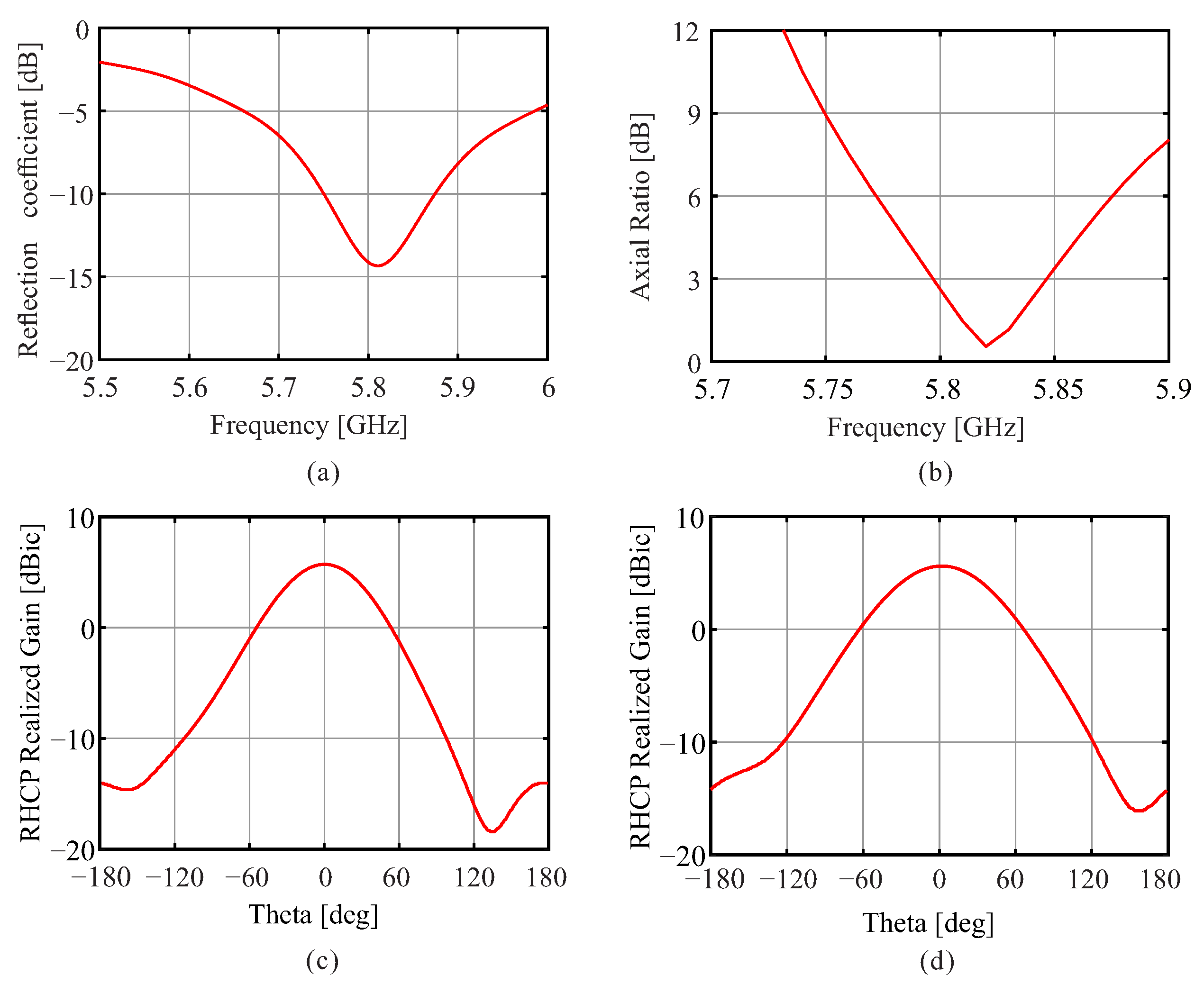
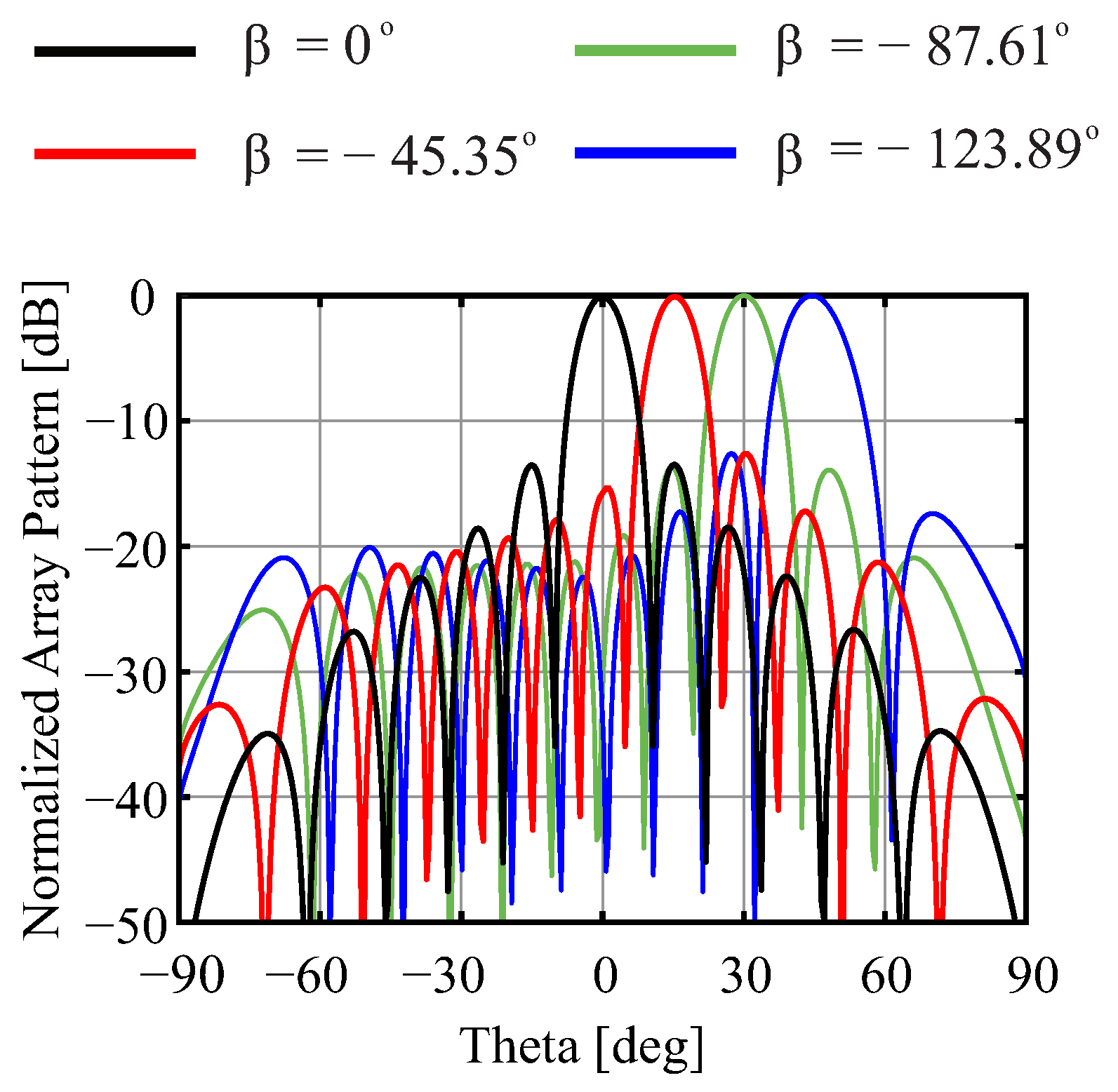
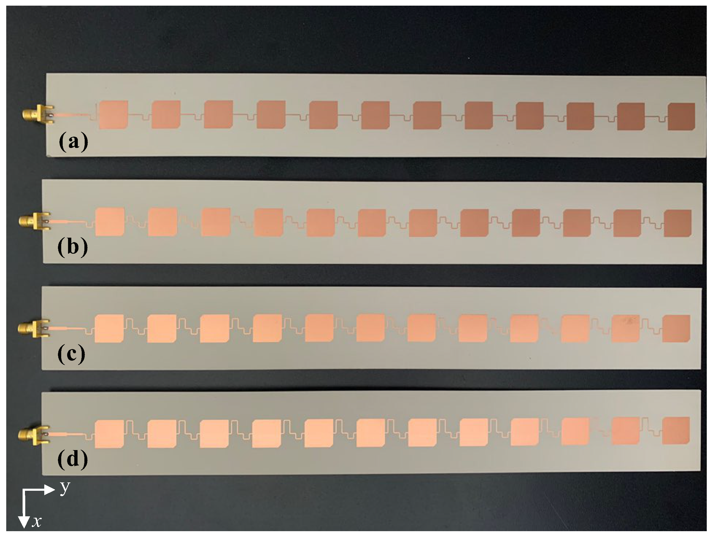
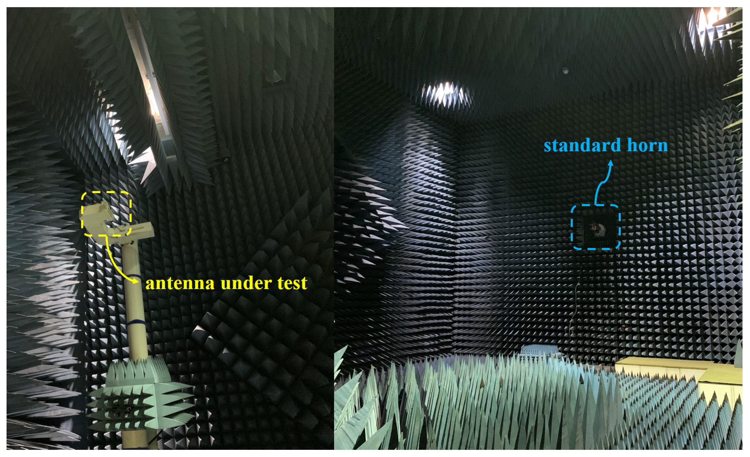
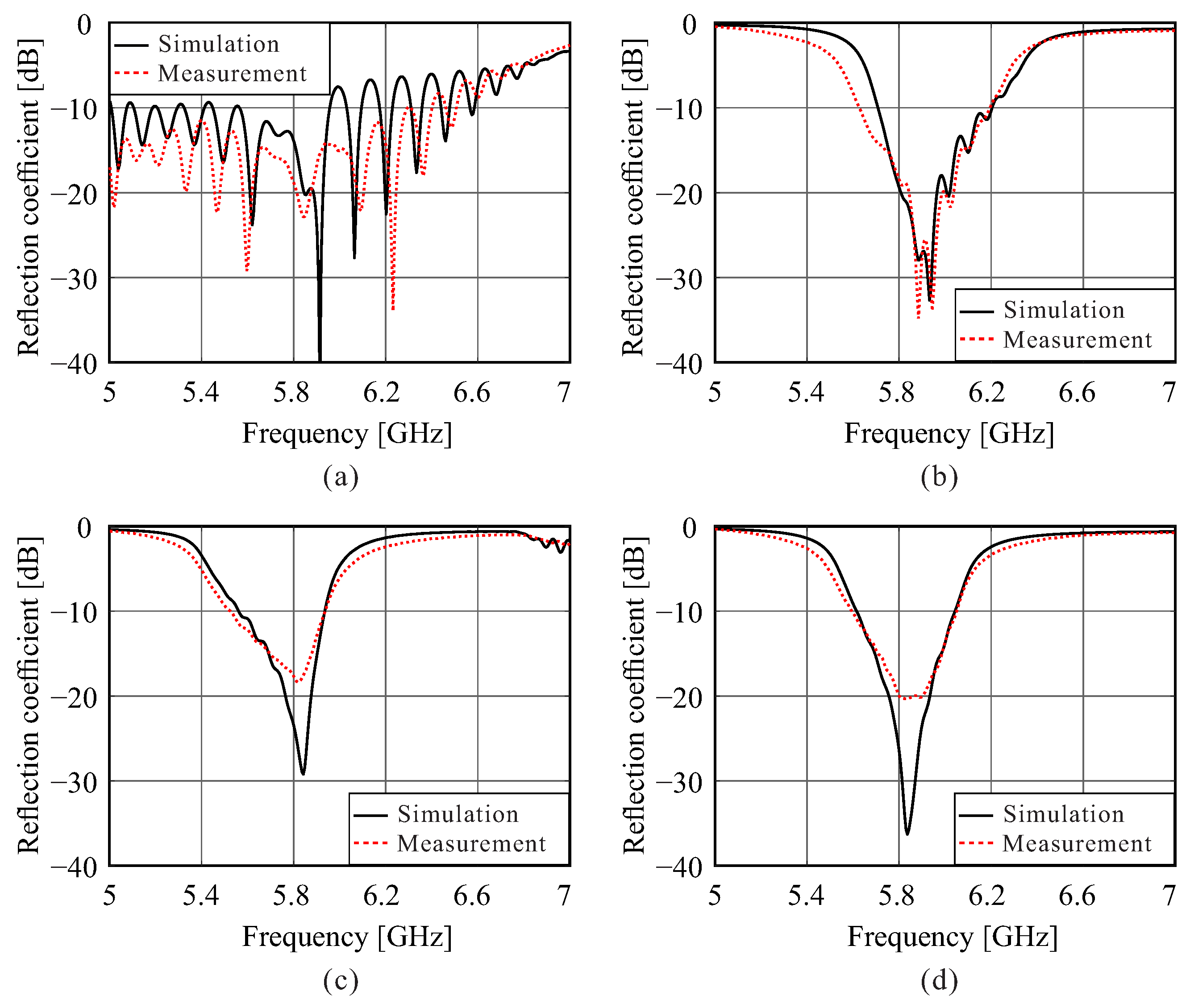
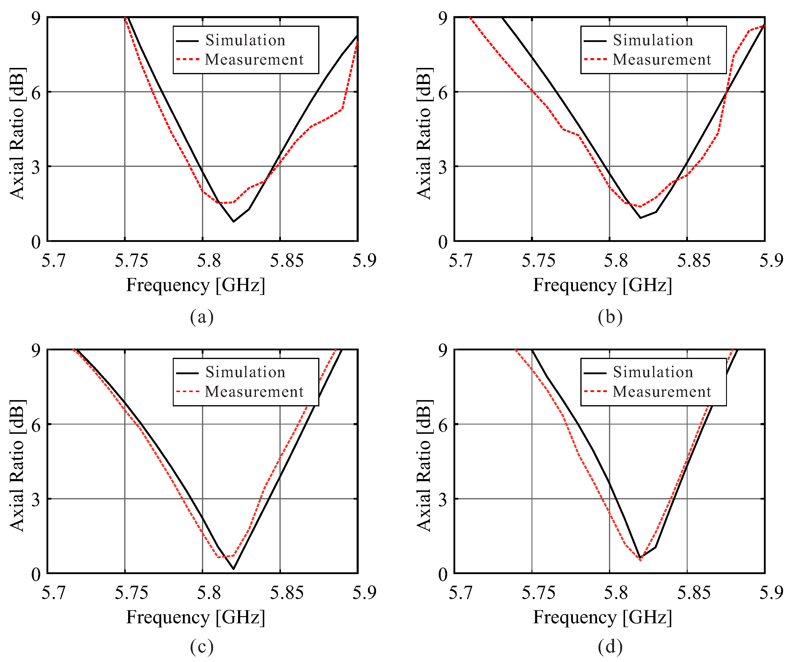
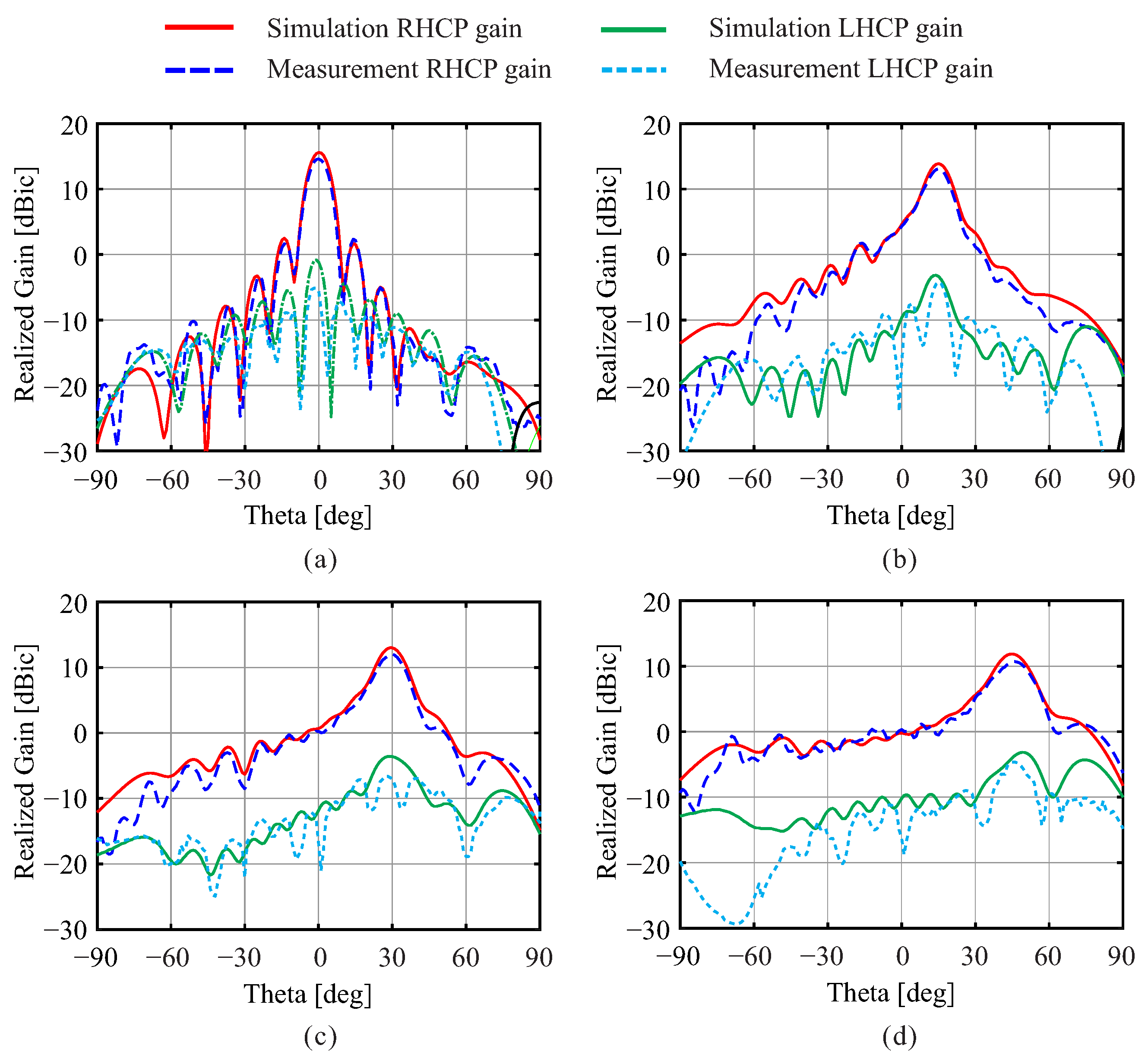
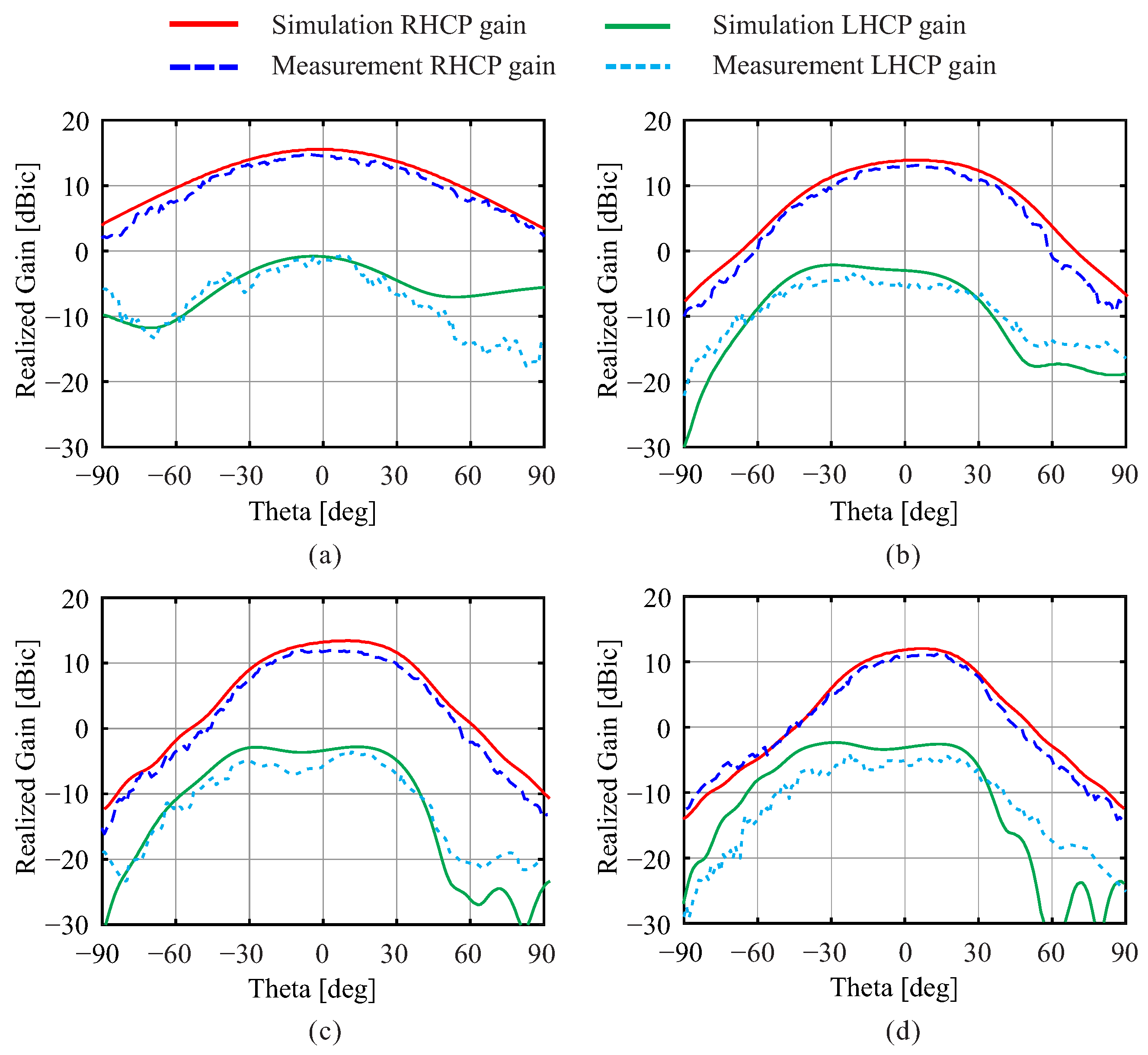
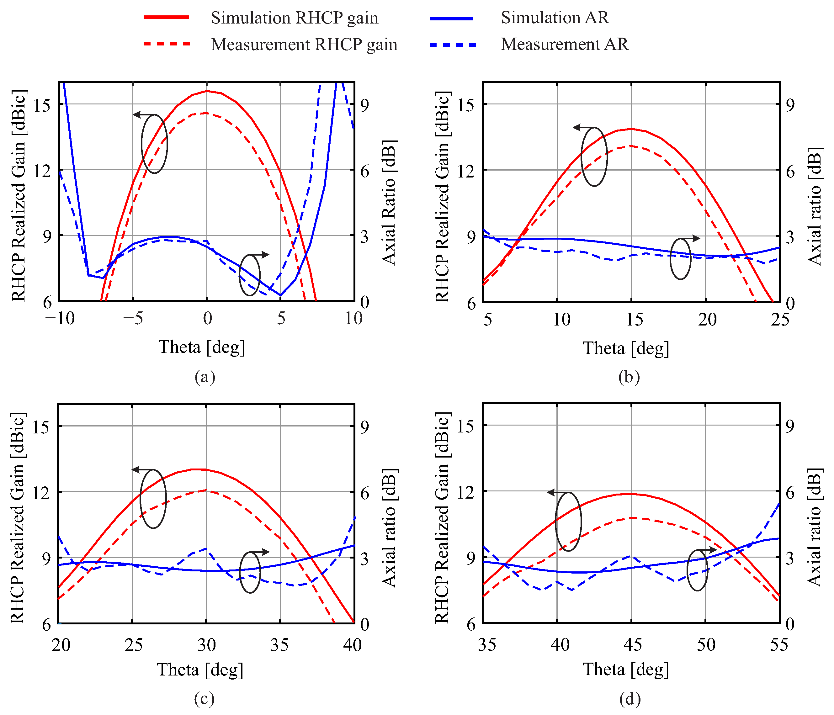
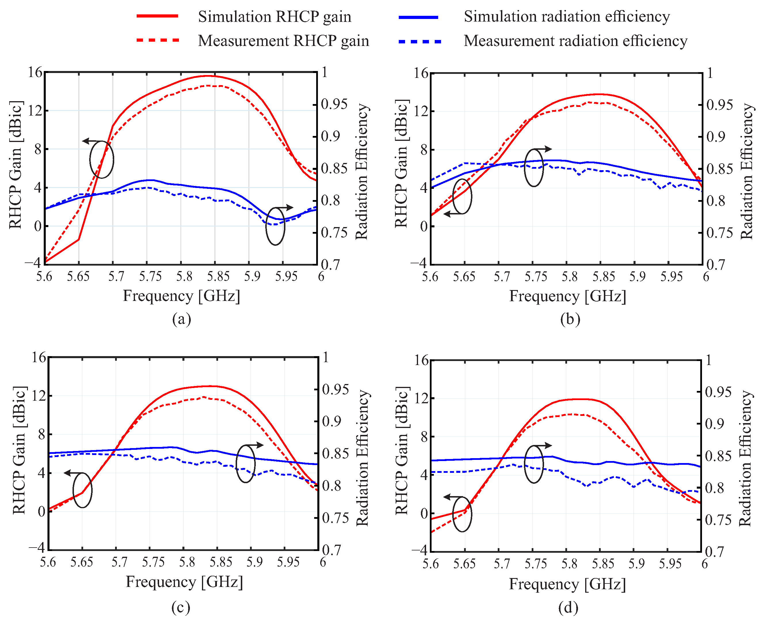
3. Experimental Results

To prove the design of the proposed series-fed antennas, prototypes of each proposed antenna according to the beam tilting angle were manufactured, as shown in Figure 11. The manufactured prototype antennas have a size of (6.22 λ 0 × 0.78 λ 0 × 0.015 λ 0 , where λ 0 is the free space wavelength at 5.84 GHz). The reflection coefficient was measured with an Agilent E8363B RF network analyzer. The AR and the radiation pattern were measured in an anechoic chamber designed for far-field measurements. A Linear Polarization (LP) standard gain horn antenna and antenna rotating technology were employed for testing, as shown in Figure 12.
Figure 13 shows the simulated and measured reflection coefficient of the proposed series-fed antennas. The measured(simulated) reflection coefficients of broadside, 15°, 30° and 45° beam tilt series-fed array antennas at 5.84 GHz are −22.5 (−19.35) dB, −21.6 (−21.8) dB, −20.24 (−35.6) dB and −17.54 (−29.1) dB in sequence. The measured (simulated) −10 dB reflection coefficient bandwidth ranges are in a row: 27.1% (6.6%), 11.1% (11.2%), 7.9% (7.2%), and 6.3% (6.4%) in a same sequence.
The simulated and measured axial ratios of each tilted angle are shown in Figure 14. The measured(simulated) axial ratios of broadside, 15°, 30° and 45° beam tilt series-fed array antennas at 5.84 GHz are sequentially 2.71 (2.35), 2.12 (2.91), 3.44 (2.65) and 2.98 (2.69) dB. The measured results are quite consistent with the simulated results, but the measured axial ratio of θ = 30° beam-tilted antenna at 5.84 GHz and its tilted angle is over 3 dB level. The measured (simulated) 3 dB AR bandwidth ranges are 5.8–5.84 (5.8–5.84) GHz, 5.78–5.84 (5.79–5.85) GHz, 5.78–5.83 (5.79–5.84) GHz and 5.79–5.84 (5.8–5.85) GHz in a row. The corresponding AR fractional bandwidth is 1.03% (0.86%), 1.03% (1.03%), 0.86% (0.86%) and 0.86% (0.86%).
Figure 15 shows simulated and measured results of realized gain patterns of the proposed series-fed antennas at 5.84 GHz. Each subplot represents different beam tilt angles of each tilted antenna, comparing RHCP and left-hand circular polarization (LHCP) gains in the ϕ = 90 plane. Figure 15a is realized gain patterns of the broadside antenna, while Figure 15b–d shows realized gain patterns of antennas with 15°, 30°, and 45° beam tilts, respectively. There is a good correlation between the simulated RHCP and LHCP gains (solid and dotted lines) and the measured RHCP and LHCP gains (dashed and dot-dashed lines). The maximum RHCP gains occur at angles θ = 0°, 15°, 30°, and 45°, as designed, and the RHCP gain patterns tend to broaden as the beam tilting angle θ increases.
Figure 16 presents the simulated and measured radiation patterns of the proposed antenna from the main lobe’s central axis in the ϕ = 0 plane, comparing RHCP and LHCP gains at 5.84 GHz. There is also a good correlation between the simulated RHCP and LHCP gains (solid and dotted lines) and the measured RHCP and LHCP gains (dashed and dot-dashed lines), similar to realized gain patterns in the ϕ = 90 plane. Additionally, since proposed series-fed array antennas are linear array antennas not for the ϕ = 0 plane, but for ϕ = 90 plane, the patterns of Figure 16 are similar to the radiation pattern of the unit cell in the ϕ = 0 plane shown in Figure 2d, with differences observed in the magnitude of the gains.
Figure 17 shows the simulated and measured RHCP gain patterns and ARs within the angular range of ±10° from tilted angle, in ϕ = 90 planes and at the operational frequency of 5.84 GHz. The measured ARs from each tilted angle stay below 3 dB within the HPBW for the proposed broadside antenna, θ = 15 , θ = 45 beam-tilted antenna. The measured AR of θ = 30 beam-tilted antenna is slightly above 3 dB at θ = 28.3 30 . The observed discrepancies between the simulated and measured results could be attributed to losses in the connecting cables and variations introduced during the manufacturing process.
Figure 18 shows both the simulated and measured RHCP gains for each angle of beam tilt, along with the radiation efficiencies as functions of frequency. Figure 18a details the RHCP gains for the broadside series-fed array antenna at a θ of 0 . Figure 18b–d show the RHCP gains for beam tilt antennas at θ = 15 , 30 , and 45 , respectively, in the ϕ = 90 plane. At the central frequency of 5.84 GHz, the measured RHCP gains of broadside series-fed array antenna, 15°, 30° and 45° beam tilt antennas are 14.59 dBic, 13.09 dBic, 12.07 dBic and 10.71 dBic, respectively, which closely align with the simulated RHCP gains of 15.52 dBic, 13.75 dBic, 12.99 dBic and 11.76 dBic in sequence. The radiation efficiencies of the antennas at 5.84 GHz range from 80.3% to 84.8% in measurements, and the simulated radiation efficiencies at 5.84 GHz are in the range of 81.9% to 86.0%. The highest RHCP gains and efficiencies are centered around the frequency of 5.84 GHz.
Table 2 summarizes the measured performance of the proposed series-fed antennas operating at 5.84 GHz, with data on impedance bandwidth, AR bandwidth, gain at tilted angles, HPBW in ϕ = 90 plane, and AR 3-dB bandwidth in ϕ = 90 plane. As the angle of beam tilting increases, both the impedance bandwidth and AR bandwidth narrow, and the gain at tilted angles decreases. Conversely, The HPBW and AR 3-dB bandwidth in the ϕ = 90 plane both widen with increased beam tilt.
Table 3 provides a comparison between the presented work with the previous literature and the proposed antenna design. The proposed antennas provide a wider tilted angle than [24,25,31,32,33], enhancing energy harvesting efficiency across a wider spatial range. Although the peak gains of the proposed beam-tilted antennas may not reach the levels achieved by the crank-line array in [32], the proposed designs have simple structures with compact sizes, streamlined structures, and more compact dimensions, rendering them advantageous for applications with spatial limitations like UAV. Furthermore, the proposed antennas provide CP compared with linear polarization (LP) works [21,24,25,31], with immunity to the polarization mismatch in diverse orientations. Refs. [22,26] were applied to WPT, with dual LP used to mitigate the decrease in transmission efficiency caused by polarization mismatches. However, this approach necessitates the use of two ports, and in the circuitry, a hybrid coupler [22] and two rectifiers [26] is employed for integration. In contrast to the array in [24], which offers a wider tilted angle, but at the expense of a larger and taller structure, proposed antennas achieve a balance between size and functionality, accommodating more radiating elements within a reduced antenna dimension. Hence, the proposed antennas are a good candidate for designing linear arrays with reduced size, CP, moderate tilted-beam angle, and low profile.

4. Conclusions

In this paper, the series-fed circularly polarized and beam-tilted microstrip patch antennas operating at 5.84 GHz were proposed, simulated, and fabricated. The proposed series-fed antennas have a radiating patch with truncated corners to implement CP without a complex feeding network. The phase between radiating patches was controlled by the length of the U-shaped bend transmission line to achieve beam-tilted, maintaining compact antenna size. The performance of the proposed series-fed antennas is confirmed by measurements, and the measurement results closely align with the simulation outcomes. The proposed antennas have peaks of measured RHCP realized gain of 14.59 dBic, 13.09 dBic, 12.07 dBic, and 10.71 dBic at the tilted-beam angles of θ = 0 , 15 , 30 , and 45 , respectively. In addition, AR performance from each tilted angle shows that it lies below 3 dB or slightly above, within HPBW. From these results, the proposed antennas are expected to be applied in various fields, such as wireless power transmission, radar, and communication systems.

Author Contributions

Writing M.Y.P. and J.H.K.; Antenna design and simulation J.H.K. and M.Y.P.; Laboratory tests M.Y.P. and J.H.K.; Methodology K.C.H.; Conceptualization M.Y.P., J.H.K., S.-h.Y., W.L., Y.Y. and K.C.H.; Writing Review and Editing K.C.H.; Resources S.-h.Y. and W.L.; Project administration S.-h.Y.; Supervision K.C.H. All authors have read and agreed to the published version of the manuscript.

Funding

This research was supported by the Korea Electrotechnology Research Institute (KERI) Primary research program of the Ministry of Science and ICT (MSIT)/National Research Council of Science and Technology (NST) (No. 24A01068).

Institutional Review Board Statement

Not applicable.

Informed Consent Statement

Not applicable.

Data Availability Statement

The data presented in this study are available in the article.

Conflicts of Interest

The authors declare no conflict of interest.

References

  1. Kim, J.; Kim, S.; Ju, C.; Son, H.I. Unmanned Aerial Vehicles in Agriculture: A Review of Perspective of Platform, Control, and Applications. IEEE Access 2019, 7, 105100–105115. [Google Scholar] [CrossRef]
  2. Maddikunta, P.K.R.; Hakak, S.; Alazab, M.; Bhattacharya, S.; Gadekallu, T.R.; Khan, W.Z.; Pham, Q.-V. Unmanned Aerial Vehicles in Smart Agriculture: Applications, Requirements, and Challenges. IEEE Sens. J. 2021, 21, 17608–17619. [Google Scholar] [CrossRef]
  3. Alsamhi, S.H.; Shvetsov, A.V.; Kumar, S.; Shvetsova, S.V.; Alhartomi, M.A.; Hawbani, A.; Rajput, N.S.; Srivastava, S.; Saif, A.; Nyangaresi, V.O. UAV Computing-Assisted Search and Rescue Mission Framework for Disaster and Harsh Environment Mitigation. Drones 2022, 6, 154. [Google Scholar] [CrossRef]
  4. Gao, J.; Hu, Z.; Bian, K.; Mao, X.; Song, L. AQ360: UAV-Aided Air Quality Monitoring by 360-Degree Aerial Panoramic Images in Urban Areas. IEEE Internet Things J. 2021, 8, 428–442. [Google Scholar] [CrossRef]
  5. Alawad, W.; Halima, N.B.; Aziz, L. An Unmanned Aerial Vehicle (UAV) System for Disaster and Crisis Management in Smart Cities. Electronics 2023, 12, 1051. [Google Scholar] [CrossRef]
  6. Nguyen, M.T.; Nguyen, C.V.; Truong, L.H.; Le, A.M.; Quyen, T.V.; Masaracchia, A.; Teague, K.A. Electromagnetic Field Based WPT Technologies for UAVs: A Comprehensive Survey. Electronics 2020, 9, 461. [Google Scholar] [CrossRef]
  7. Wang, X.; Wu, P.; Hu, Y.; Cai, X.; Song, Q.; Chen, H. Joint Trajectories and Resource Allocation Design for Multi-UAV-Assisted Wireless Power Transfer with Nonlinear Energy Harvesting. Drones 2023, 7, 354. [Google Scholar] [CrossRef]
  8. Brown, W. Experiments Involving a Microwave Beam to Power and Position a Helicopter. IEEE Trans. Aerosp. Electron. Syst. 1969, AES-5, 692–702. [Google Scholar] [CrossRef]
  9. Schlesak, J.J.; Alden, A.; Ohno, T. A microwave powered high altitude platform. In Proceedings of the IEEE MTT-S International Microwave Symposium Digest, New York, NY, USA, 25–27 May 1988; pp. 283–286. [Google Scholar]
  10. Song, K.D.; Kim, J.; Kim, J.W.; Park, Y.; Ely, J.J.; Kim, H.J.; Choi, S.H. Preliminary operational aspects of microwave-powered airship drone. Int. J. Micro Air Veh. 2019, 11, 1–10. [Google Scholar] [CrossRef]
  11. Hoque, M.U.; Kumar, D.; Audet, Y.; Savaria, Y. Design and Analysis of a 35 GHz Rectenna System for Wireless Power Transfer to an Unmanned Air Vehicle. Energies 2022, 15, 320. [Google Scholar] [CrossRef]
  12. Matsukura, M.; Moro, R.; Keicho, N.; Shimamura, K.; Yokota, S. Wireless Charging for Hovering-Drone via Millimeter Wave. In Proceedings of the 2022 Wireless Power Week (WPW), Bordeaux, France, 5–8 July 2022; pp. 772–775. [Google Scholar]
  13. Takabayashi, N.; Kawai, K.; Mase, M.; Shinohara, N.; Mitani, T. Large-Scale Sequentially-Fed Array Antenna Radiating Flat-Top Beam for Microwave Power Transmission to Drones. IEEE J. Microw. 2022, 2, 297–306. [Google Scholar] [CrossRef]
  14. Liu, X.; Xu, B.; Zheng, K.; Zheng, H. Throughput Maximization of Wireless-Powered Communication Network with Mobile Access Points. IEEE Trans. Wirel. Commun. 2023, 22, 4401–4415. [Google Scholar] [CrossRef]
  15. Xu, J.; Zeng, Y.; Zhang, R. UAV-Enabled Wireless Power Transfer: Trajectory Design and Energy Optimization. IEEE Trans. Wirel. Commun. 2018, 17, 5092–5106. [Google Scholar] [CrossRef]
  16. Yuan, X.; Hu, Y.; Schmeink, A. Joint Design of UAV Trajectory and Directional Antenna Orientation in UAV-Enabled Wireless Power Transfer Networks. IEEE J. Sel. Areas Commun. 2021, 39, 3081–3096. [Google Scholar] [CrossRef]
  17. Roy, S.; Mahin, R.; Mahbub, I. A Comparative Analysis of UWB Phased Arrays with Combining Network for Wireless-Power-Transfer Applications. IEEE Trans. Antennas Propag. 2023, 71, 3204–3215. [Google Scholar] [CrossRef]
  18. Hasegawa, N.; Ohta, Y. 2-Dimensional Simple Beam Steering for Large-Scale Antenna on Microwave Power Transfer. IEEE Trans. Microw. Theory Tech. 2022, 70, 2432–2441. [Google Scholar] [CrossRef]
  19. Ide, M.; Shirane, A.; Yanagisawa, K.; You, D.; Pang, J.; Okada, K. A 28-GHz Phased-Array Relay Transceiver for 5G Network Using Vector-Summing Backscatter with 24-GHz Wireless Power and LO Transfer. IEEE J. Solid State Circuits 2022, 57, 1211–1223. [Google Scholar] [CrossRef]
  20. Eid, A.M.; Alieldin, A.; El-Akhdar, A.M.; El-Agamy, A.F.; Saad, W.M.; Salama, A.A. A novel high power frequency beam-steering antenna array for long-range wireless power transfer. Alex. Eng. J. 2021, 60, 2707–2714. [Google Scholar] [CrossRef]
  21. Li, M.; Li, S.-K.; Tang, M.-C.; Zhu, L. A Compact, Single-Layer, Index-Modulated Microstrip Antenna with Stable Customized Tilted Beam Over a Wide Bandwidth. IEEE Trans. Antennas Propag. 2022, 70, 11465–11474. [Google Scholar] [CrossRef]
  22. Zhou, W.L.; Zhu, G.X.; Wang, J.C.; Zhang, H. Symmetrically +/−45° Dual-Polarized Rectenna Array for Orthogonally and/or Two-Tone Excited Polarization-Insensitive and Wide-Coverage MPT. In Proceedings of the 2023 IEEE MTT-S International Microwave Workshop Series on Advanced Materials and Processes for RF and THz Applications (IMWS-AMP), Chengdu, China, 13–15 November 2023; pp. 1–3. [Google Scholar]
  23. Mishra, P.K.; Jahagirdar, D.R.; Kumar, G. Tilted beam microstrip antenna array conformai to cylindrical section. In Proceedings of the IEEE International Conference on Antenna Innovations & Modern Technologies for Ground, Aircraft and Satellite Applications (iAIM), Bangalore, India, 24–26 November 2017; pp. 1–6. [Google Scholar]
  24. Alshrafi, W.; Al-Bassam, A.; Heberling, D. Grating Lobe Reduction Using Tilted Beam Unit Cell in Series-Fed Patch Periodic Leaky-Wave Antennas. In Proceedings of the 15th European Conference on Antennas and Propagation (EuCAP), Dusseldorf, Germany, 22–26 March 2021; pp. 1–5. [Google Scholar]
  25. Du, H.; Li, Z.; Chen, M.; Wang, J. A Broadband Fixed-Beam Leaky-Wave Antenna. IEEE Trans. Antennas Propag. 2023, 71, 5434–5439. [Google Scholar] [CrossRef]
  26. Hu, Y.-Y.; Sun, S.; Su, H.-J.; Yang, S.; Hu, J. Dual-Beam Rectenna Based on a Short Series-Coupled Patch Array. IEEE Trans. Antennas Propag. 2021, 69, 5617–5630. [Google Scholar] [CrossRef]
  27. Boskovic, N.; Jokanovic, B.; Radovanovic, M. Printed Frequency Scanning Antenna Arrays with Enhanced Frequency Sensitivity and Sidelobe Suppression. IEEE Trans. Antennas Propag. 2017, 65, 1757–1764. [Google Scholar] [CrossRef]
  28. Zahid, Z.; Qu, L.; Kim, H.-H.; Kim, H. Circularly Polarized Loop-Type Ground Radiation Antenna for IoT Applications. J. Electromagn. Eng. Sci. 2019, 19, 153–158. [Google Scholar] [CrossRef]
  29. Chen, Y.T.; Lin, X.Q.; Fan, Y.; Liu, S.L. Generation of Ka-Band Accelerating and Self-Bending Beam by Series-Fed Patch Array. IEEE Antennas Wirel. Propag. Lett. 2021, 20, 239–243. [Google Scholar] [CrossRef]
  30. Balanis, C.A. Antenna Theory: Analysis and Design, 4th ed.; John Wiley & Sons, Inc.: Hoboken, NJ, USA, 2015. [Google Scholar]
  31. Shi, J.; Zhu, L.; Liu, N.-W.; Wu, W. A Microstrip Yagi Antenna with an Enlarged Beam Tilt Angle via a Slot-Loaded Patch Reflector and Pin-Loaded Patch Directors. IEEE Antennas Wirel. Propag. Lett. 2019, 18, 679–683. [Google Scholar] [CrossRef]
  32. Hirose, K.; Orihara, K.; Nakano, H. Formation of a Circularly Polarized Tilted Beam Using Radiation Cells of a Crank-line Antenna. Electron. Commun. Jpn. 2001, 84, 23–30. [Google Scholar] [CrossRef]
  33. Sumantyo, J.T.S. Design of tilted beam circularly polarized antenna for CP–SAR sensor onboard UAV. In Proceedings of the International Symposium on Antennas and Propagation (ISAP), Okinawa, Japan, 24–28 October 2016; pp. 658–659. [Google Scholar]
Figure 1. Configuration of the proposed series-fed antennas: (a) beam-tilted antenna, (b) broadside antenna.
Applsci 14 03490 g001
Figure 2. Simulated results of the patch of unit cell: (a) reflection coefficient, (b) AR, (c) RHCP realized gain in ϕ = 90 plane, and (d) RHCP realized gain in ϕ = 0 plane.
Applsci 14 03490 g002
Figure 3. Simulated surface current distributions of the patch of the unit cell with period T at 5.84 GHz: (a) t = 0, (b) t = T / 4 , (c) t = T / 2 , and (d) t = 3 T / 4 .
Applsci 14 03490 g003
Figure 4. Parameter study of the unit cell for varying L p : (a) reflection coefficient, (b) AR.
Applsci 14 03490 g004
Figure 5. Parameter study of the unit cell for varying a: (a) reflection coefficient, (b) AR.
Applsci 14 03490 g005
Figure 6. Calculated and normalized radiation pattern of the linear array antenna for different β at 5.84 GHz.
Applsci 14 03490 g006
Figure 7. Simulated results for different W 2 : (a) phase of the transmission coefficient of the unit cell, (b) RHCP realized gain patterns of the series-fed antennas at 5.84 GHz, in ϕ = 90 plane, (c) reflection coefficient of the series-fed antennas, and (d) axial ratio of the series-fed antennas at each beam tilting angle.
Applsci 14 03490 g007
Figure 8. Simulated RHCP realized gain patterns for different W 2 at 5.84 GHz, in ϕ = 90 plane: (a) 1 × 12 series-fed antennas of the proposed unit cell, (b) 1 × 6 series-fed antennas of the proposed unit cell.
Applsci 14 03490 g008
Figure 9. Configuration of matching network of the proposed antennas: (a) broadside antenna, (b) beam-tilted antenna.
Applsci 14 03490 g009
Figure 10. Simulated impedance characteristics of matching network: (a) reflection coefficient and transmission coefficient of impedance-matching network, (b) input impedance of the broadside series-fed antenna, and (c) reflection coefficient of the broadside series-fed antenna.
Applsci 14 03490 g010
Figure 11. Photographs of the fabricated series-fed antennas prototype: (a) broadside antenna, (b) θ = 15 beam-tilted antenna, (c) θ = 30 beam-tilted antenna, and (d) θ = 45 beam-tilted antenna.
Applsci 14 03490 g011
Figure 12. Measurement setup in an anechoic chamber.
Applsci 14 03490 g012
Figure 13. Simulated and measured reflection coefficient of the proposed series-fed antennas: (a) broadside antenna, (b) θ = 15 beam-tilted antenna, (c) θ = 30 beam-tilted antenna, and (d) θ = 45 beam-tilted antenna.
Applsci 14 03490 g013
Figure 14. Simulated and measured axial ratio of the proposed series-fed antennas: (a) broadside antenna, (b) θ = 15 beam-tilted antenna, (c) θ = 30 beam-tilted antenna, and (d) θ = 45 beam-tilted antenna.
Applsci 14 03490 g014
Figure 15. Simulated and measured radiation patterns of the proposed antennas at 5.84 GHz in ϕ = 90 plane: (a) broadside antenna, (b) θ = 15 beam-tilted antenna, (c) θ = 30 beam-tilted antenna, and (d) θ = 45 beam-tilted antenna.
Applsci 14 03490 g015
Figure 16. Simulated and measured radiation patterns of the proposed antennas in ϕ = 0 plane at 5.84 GHz: (a) broadside antenna, (b) θ = 15 beam-tilted antenna, (c) θ = 30 beam-tilted antenna, and (d) θ = 45 beam-tilted antenna.
Applsci 14 03490 g016
Figure 17. Simulated and measured AR and RHCP gain patterns of the proposed antennas at 5.84 GHz in ϕ = 90 plane at the tilted angles: (a) broadside antenna, (b) θ = 15 beam-tilted antenna, (c) θ = 30 beam-tilted antenna, and (d) θ = 45 beam-tilted antenna.
Applsci 14 03490 g017
Figure 18. Simulated and measured RHCP gains at each tilted angle and radiation efficiencies of the proposed antennas: (a) broadside antenna, (b) θ = 15 beam-tilted antenna, (c) θ = 30 beam-tilted antenna, and (d) θ = 45 beam-tilted antenna.
Applsci 14 03490 g018
Table 1. Design parameters of the proposed antennas (unit: millimeters).
ParameterValueParameterValue
L s u b 25 L 1 1.6
W s u b 40 L 2 2.45
L p 13.7 L 3 1.6
a 1.39 L 4 5.65
b 0.57 W 1 1.09
W T L 0.4
W 2 broadside0 W p broadside13.7
beam-tilted
θ = 15
1.2beam-tilted
θ = 15
13.4
beam-tilted
θ = 30
2.1beam-tilted
θ = 30
13.45
beam-tilted
θ = 45
2.9beam-tilted
θ = 45
13.45
Table 2. The measured impedance bandwidth, AR bandwidth, RHCP realized gain, HPBW, and AR 3-dB beamwidth of the proposed antennas at 5.84 GHz.
Impedance Bandwidth [GHz]AR Bandwidth [GHz]Gain at a Tilted Angle [dBic]HPBW in ϕ = 90 Plane [deg]AR 3-dB BW in ϕ = 90 Plane [deg]
Broadside antenna4.79∼6.29
(27.1%)
5.8∼5.84
(1.03%)
14.598.914.2
θ = 15 beam-tilted antenna5.62∼6.28
(11.1%)
5.78∼5.84
(1.03%)
13.0911.224.3
θ = 30 beam-tilted antenna5.59∼6.05
(7.9%)
5.78∼5.83
(0.86%)
12.0713.318.5
θ = 45 beam-tilted antenna5.52∼5.88
(6.3%)
5.79∼5.84
(0.86%)
10.7116.515.9
Table 3. Comparison of the proposed antenna with the previous works.
Refs.Center Freq. [GHz]Array SizeGainPolarizationTilted AngleAntenna Dimension ( λ 0 )Application
[21]5.91 × 79.7 dBiLP50°0.415 × 1.6 × 0.079Not WPT
[22]6.81 × 211 dBiDual LP−45°,45°NGWPT
[24]6.11 × 711 dBiLP−30∼30°6.1 × 1.02 × 0.14Not WPT
[25]321 × 109.7∼15.7 dBiLP−25°, 0°, 25°NGNot WPT
[26]2.451 × 58.5 dBiDual LPNG1.23 × 0.65 × 0.033WPT
[31]51 × 47.2∼8.9 dBiLP36∼56°1.66 × 0.83 × 0.025Not WPT
[32]NG1 × 413.5 dBicCP20°, 45°14 × 10 × 0.25Not WPT
[33]1.271 × 411.2 dBicCP20°NGNot WPT
Prop.5.841 × 1214.59∼10.71 dBicCP0°, 15°, 30°, 45°6.22 × 0.78 × 0.015WPT
NG: Not given.
Disclaimer/Publisher’s Note: The statements, opinions and data contained in all publications are solely those of the individual author(s) and contributor(s) and not of MDPI and/or the editor(s). MDPI and/or the editor(s) disclaim responsibility for any injury to people or property resulting from any ideas, methods, instructions or products referred to in the content.

