Article

Practical Steps towards Establishing an Underwater Acoustic Network in the Context of the Marine Internet of Things

1
Research Laboratory of Robotics and Intelligent Control Systems, Sevastopol State University, Sevastopol 299053, Russia
2
Independent Researcher, Sevastopol 299006, Russia
*
Author to whom correspondence should be addressed.
Appl. Sci. 2024, 14(8), 3527; https://doi.org/10.3390/app14083527
Submission received: 12 March 2024 / Revised: 10 April 2024 / Accepted: 17 April 2024 / Published: 22 April 2024
(This article belongs to the Special Issue Autonomous Underwater Vehicles (AUVs): Applications and Technologies)

Abstract

:
When several hydroacoustic modems operate simultaneously in an area of mutual coverage, collisions of data packets received from several sources may occur, which lead to information loss. With an increase in the number of simultaneously operating hydroacoustic modems, physical layer algorithms do not provide stable data transmission and the likelihood of collisions increases, which makes the operation of modems ineffective. To ensure effective operation in a hydroacoustic signal propagation environment and to reduce collisions when exchanging data between two modems that do not have the ability to operate synchronously and to reduce the access time to the signal propagation environment, methods of the medium access control layer using link layer protocols are required. Typically, this problem is solved using code separation of hydroacoustic channels. If you need to transfer over a network, this option will not work, since network transfer involves working on the basis of “broadcast” messages, particularly between data source and data sink that remain too far from each other, outside of their mutual audibility. In practical use, it is convenient to place these protocols into a software environment for developing specific user applications for solving network communication problems. This software framework allows for custom modification of existing network algorithms, as well as the inclusion of new network hydroacoustic communication algorithms. To build a predictive model, the DACAP, T-Lohi, Flooding, and ICRP protocols were used in this work. The implementation is performed in Erlang. The paper presents algorithms for implementing these protocols. A comparative analysis of network operation with and without protocols is provided. Efficiency of operation, i.e., data rates and probabilities of data delivery, was assessed.

1. Introduction

In the domain of Marine Internet of Things (MIoT), there exists a backlog of technical solutions capable of expediting practical outcomes, particularly in the pursuit of establishing underwater hydroacoustic networks [1].
Underwater systems that operate simultaneously, including autonomous and remotely operated underwater vehicles (AUV/ROV), underwater sensors, and buoys, necessitate continuous data exchange [2,3,4,5]. The same principle applies to devices functioning as a part of group, considering the changing network geometry resulting from changes in the relative positions of these devices [6].
MIoT provides a range of wireless communication and networking choices. These options include acoustic, optical, radio frequency, and magnetic fusion communications for data transmission. Among these, acoustic communication is particularly well suited for the underwater environment due to its ability to transmit over long distances, ranging from several hundred meters to tens of kilometers [1,7,8,9]. However, it does come with several limitations, such as low bandwidth, high intensity, long-duration reverberation, relatively large Doppler spectrum expansion, etc. [10,11].
The process of addressing data transmission challenges via the hydroacoustic channel entails integrating hydroacoustic modems into the sensor modules of underwater devices [12]. Typically, underwater acoustic modems are most effective when dealing with a limited number of asynchronously interacting data sources or recipients.
When multiple acoustic modems operate simultaneously within an overlapping area, collisions of data packets received from various sources can occur. These collisions result in the loss of some or all information. As the number of concurrently operating hydroacoustic modems increases, the stability of data transmission provided by physical layer algorithms diminishes, and the probability of collisions rises. Consequently, the effective operation of modems becomes compromised, and in some cases, even unfeasible.
In the context of airspace, numerous methods exist for routing and resolving data collisions [13]. However, in hydroacoustics, these methods may not always be employed and are typically subjected to significant limitations.
To ensure effective operation in a hydroacoustic signal propagation environment and to minimize or eliminate collisions during data exchange and delivery between two modems that lack synchronous operation capability, as well as to reduce access time to the signal propagation environment, methods from the media access control layer that utilize data link layer protocols are necessary.
Typically, this problem is addressed by employing code division or frequency division across hydroacoustic channels, i.e., when modems operate at distinct frequencies, ensuring non-interference. This enables underwater network subscribers to communicate either in a “point-to-point” (P2P) format or in “multicast” mode, where each communication occurs independently. However, if network-wide transmission is required, this approach becomes unsuitable, as network transmission relies on “broadcast” messages and some network nodes, particularly data source and data sink, which can stay too far from each other, outside of their mutual audibility (operation ranges).
For transmitting data in a hydroacoustic network with constantly changing conditions of emission and reception of signals, specialized network protocols have recently been developed. These protocols can consider and utilize a dynamically varying number of network nodes situated in the region of mutual audibility or (due to the asymmetry of communication channel characteristics) one-way audibility. An essential focus in creating network communication techniques is the design of algorithms for forming the so-called ad hoc networks [14,15,16].
To manage multiple devices within the same coverage area, specialized network layer protocols are essential. These protocols facilitate broadcasting across the underwater network, even between data source and data sink that are separated by large distances by the means of intermediate network nodes, so called relay nodes. Additionally, data link layer protocols handle collisions between data packets [17,18,19,20,21,22].
In practical applications, these protocols are typically integrated into the software development environment (framework) of specific user applications to address network communication issues. Such a framework is commonly referred to as a software framework, which enables users to modify the existing network algorithms within the framework and incorporate new network communication algorithms as needed.
The article outlines an approach of developing Marine Internet of Things (IoT) [1] systems. This approach relies on leveraging the existing technical foundations in the domain of hydroacoustic modems and software frameworks. By doing so, it aims to enhance the functionality of these modems, effectively transforming them into network devices.
For underwater communication systems, there are currently four advanced software frameworks known for integrating heterogeneous communication devices and transforming them into network devices. These frameworks also allow the flexible integration of modems with various sensor devices, including actuators, drive mechanisms, manipulators, and sensor systems. The following software frameworks exist in the public domain and have the following names: (1) SUNSET (developed by Sapienza University, Italy) [14], (2) DESERT (developed by the University of Padua, Italy) [23], (3) UnetStack (developed by the National University of Singapore) [5], and (4) EviNS (developed by Evologics, Germany) [24].
The EviNS software [24] URL: https://github.com/okebkal/evins.git (accessed on 5 October 2022) framework is the least resource-intensive option. It offers users a broad spectrum of capabilities for integrating different software modules, peripherals, and systems. It can run in real time on a low-performance processor platform, including directly on the computing platform of a hydroacoustic modem or one of the integrated devices.
The EviNS (Evologics Intelligent Networking Software Framework) software framework [24] is a compact open-source software developed in the Erlang programming language. One of its advantages is that a set of basic programs implementing access control protocols and routing protocols are already included in the framework.
As a part of the EviNS software framework development, two hydroacoustic modems were chosen for testing: the uWAVE, manufactured by the Underwater Communications and Navigation Laboratory in Russia, and the hydroacoustic S2C series modem, produced by Evologics, Germany.
To leverage the extensive capabilities of the EviNS software framework, user applications were designed in the form of environment access control layer protocols and network layer protocols. These applications were equipped to handle various roles, which, in turn, enabled the technical integration of modems from different manufacturers into the EviNS software framework. Specifically, a uWave modem command parser was developed to incorporate the uWave modem into the program framework. For the development of user software aimed at addressing network communication challenges in Marine Internet of Things (IoT) systems, the **EviNS software framework** is recommended as a versatile tool. It can be deployed either on a third-party computer or directly on the hydroacoustic modem computing platform. When executed, it seamlessly integrates with the standard hydroacoustic modem software, transforming the modest hydroacoustic modem from a basic simplex digital communication device into a fully functional network communication node.
This paper makes the following contributions:
  • A model for constructing hydroacoustic networks that allows taking into account potential implementations with modems from different manufacturers as nodes in this network.
  • Creation of a software platform for developing and configuring proprietary algorithms for transmitting data via a hydroacoustic communications channel, which enables the modification of the existing algorithms and the inclusion of new communication techniques to achieve optimal settings for information transfer underwater.
  • Presentation of a comparative evaluation of network performance with and without different protocols, allowing the assessment of data transfer rates and the probability of successful delivery.
The article is organized as follows. Section 2 highlights the versatility of the software network add-in, demonstrating its ability to “unlink” from execution on specific hardware and software platforms of the hydroacoustic modem. It also explores the potential for modifying the existing protocols within the access control layer and data routing protocols. Section 3 considers the concept of constructing the EviNS software framework. Section 4 provides details on the implementation of network and link layer protocols, which enable data transmission even in conditions of relatively low network dynamics while minimizing energy consumption per unit of data delivered to the recipient. Finally, Section 5 presents the findings from experimental studies, followed by a discussion of the results and conclusions.

2. Versatility of the Software Network Add-In of the Hydroacoustic Modem

From the deployment and usage perspective, the versatility of the EviNS software framework across various computational platforms is ensured by two factors. Firstly, the creation of the EviNS software framework in the Erlang programming language provides a foundation for its adaptability. Secondly, the ability for the cross-platform compilation of the software framework, written in Erlang, further enhances its versatility.
Ensuring these two conditions, after cross-platform compilation, for instance, on a desktop PC, the EviNS software framework can also be deployed on other platforms, particularly on embedded (low-power) computing platforms with relatively low performance.
A distinctive feature of EviNS is its utilization of the Erlang programming language for its development, characterized by a number of advantages such as built-in support for parallelism with distribution and duplication of computational processes, resulting in fault tolerance. Erlang applications have proven themselves in large telecommunication systems (distributed, reliable, soft real-time parallel systems). Another significant advantage of Erlang is its open-source nature URL: http://www.erlang.org (accessed on 5 October 2022) and a large number of OTP (Open Telecom Platform) libraries, enabling a wide range of actions in telecommunication systems, from compiling ASN.1 applications (in a language describing the abstract syntax of data used in the OSI telecommunication architecture) to developing various user applications in Erlang and creating web servers. Moreover, OTP libraries are also accompanied by open-source code. Erlang/OTP has its own program execution environment, called the BEAM virtual machine. Using BEAM, Erlang source code can be compiled into bytecode, which is a set of instructions understood by both the compiler and the Erlang runtime environment. Compiled code managed by BEAM on one computing platform can then be executed on other computing platforms containing the same BEAM virtual machine. Thanks to this capability, applications written in Erlang can run on various computing platforms, providing high flexibility in using an application once written without the need for extensive code reworking for other computing platforms.
Furthermore, there is the possibility of cross-compiling an Erlang application for use even on platforms that are incapable of running an operating system. In such cases, the so-called “dockers” provided by the manufacturers of computing platforms are typically used. A docker can be deployed on any general-purpose computing machine (usually running on the Linux operating system) to simulate the computing environment of the target processor. By placing the BEAM virtual machine in a docker, it can facilitate the compilation of Erlang/OTP with subsequent transfer of the resulting code to the target processor for execution. Additionally, by creating user applications in the Erlang language and compiling these applications on a general-purpose computing machine using the BEAM virtual machine, the resulting BEAM files can also be transferred for execution on the target processor simply by copying them.
In preparing the materials for the current article, the advantages of the universality of the EviNS software framework were utilized. Specifically, after its cross-platform compilation on a desktop PC with OS Linux Debian and the Erlang virtual machine, the resulting set of compiled BEAM files was transferred to another computing platform where OS Linux Debian and the Erlang virtual machine were also installed. However, this computing platform was no longer a desktop PC but instead was a compact platform, the ODROID H2. In general, program execution can also be achieved on computing platforms such as System-on-Module (SoM) with integrated ARM processors, including the NVIDIA Jetson NX, Microchip Atmel, or Raspberry Pi.
From the perspective of user programs developed for the EviNS software framework, the universality of the software networking overlay of the modem was ensured by the inherent framework approach for constructing EviNS. In this approach, any program configuration consisted of two parts: the first, constant part, i.e., the framework itself, which remained unchanged from one configuration to another but contained slots where the second (variable) part could be placed, and interchangeable modules or extension points. With this approach, user programs created and compiled on a PC were simply added to the deployed EviNS framework on another computing platform by straightforwardly copying them as BEAM files.
Thus, user programs could be developed for the EviNS software framework, for example, on a desktop PC, and then simply copied for execution on another computing platform, such as a modem platform (with the EviNS framework already deployed on it), without the need to recompile the entire code on the new platform (i.e., both the framework code and the newly added module code).
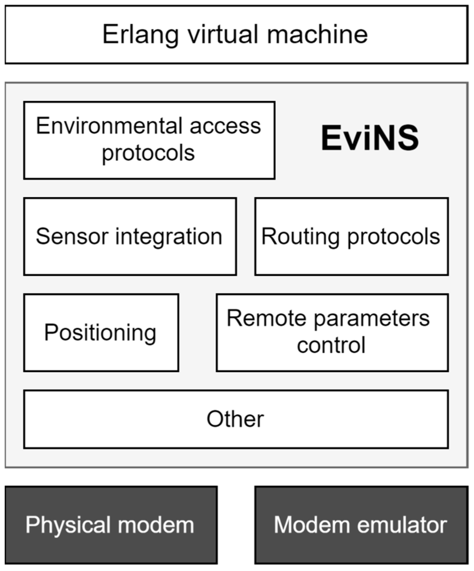
Figure 1 illustrates the architecture of the EviNS software framework URL: https://github.com/EvoLogics/evins/wiki (accessed on 5 October 2022), which (according to the framework construction concept) includes a set of independently operating processes, each defined as a finite state machine, with these finite state machines being controlled by external and internal events.
From the perspective of the interaction between the user application and the modem, the universality of the EviNS software framework is in the development of the network modem’s command interface as an open-ended list. This means that, in addition to the initial set of network-level commands provided by the framework developer, allowing the control of the modem, and a set of acknowledgments (which the modem returns to the user application to notify it of the details of command execution), users were also given the opportunity to develop their own additional commands and macros based on them, thus modifying/extending the functional capabilities laid down by the software framework developer.
Therefore, the EviNS software framework can be considered as a universal tool for users to develop their own applications, which can be executed on the computing platform of their choice from a wide range of models. Moreover, a significant convenience is the ability to focus solely on the “core work”, creating applications of practical interest, without being distracted by numerous peripheral tasks related to the specifics of the computing platform, or the need to link the developed application with a multitude of processes in the computing environment to ensure its functioning. This work is performed for the user by the constant part of the software framework.
In general, for the development of user applications (protocols of the data link and network layers), the EviNS software framework was considered universal in terms of the following:
  • Its deployment and usage on various computing platforms, particularly its capability for cross-platform compilation on a desktop PC (with OS Linux Debian and the Erlang virtual machine) followed by transfer to another computing platform (the experimental part was conducted on the Odroid H2 computing platform).
  • The framework approach for constructing EviNS, where the user application comprised two parts: a constant part, which the user did not modify (it facilitated interaction with the computing environment), and a variable part (it contained the user module and facilitated the operation of the application according to the user’s algorithm of practical interest).
  • The interaction between the user application and the modem, for example, where the set of commands of the data link and network layer protocols remained unchanged for modems from different manufacturers; the only thing that changed was the syntax analyzer of commands, adapting the command set of a modem from a specific manufacturer to the command set typical for the software framework.
Previously, there have been no instances found in the literature of using the EviNS software framework to integrate modems from third-party manufacturers into underwater networks (i.e., modems not being manufactured by Evologics company, Berlin, Germany).
Therefore, in this article, before discussing an example of using the EviNS software framework to develop a user application (a set of network layer protocols) for modems from a third-party manufacturer, it is advisable to examine the concept of constructing the EviNS software framework in more detail.

3. The Concept of Building the EviNS Software Framework

As mentioned earlier, the EviNS software framework is distributed under an open-source license, such as GPL/MIT. In this form, the EviNS software framework can be used in educational processes or in initial research in the development of the Internet of Things in the maritime domain. However, the software framework may also include numerous user libraries with closed-source code, thereby prohibiting the free distribution of a user’s (specialized) version of the software framework. This type of usage of EviNS is intended for developers of commercial software products, particularly in the creation of industrial products for the Internet of Things in the maritime domain. (According to the terms of the license, in this case, the developer of the commercial software product is obliged to pay a licensing fee to the developer of the open-source software framework.)
As depicted in Figure 1, the EviNS software framework is based on the utilization of the Erlang virtual machine and comprises a set of independently operating agents. Furthermore, the implementation of the EviNS software framework adheres to the design principles of Erlang/OTP concerning the structure of code written in the Erlang language, as well as its processes, modules, and directories. Figure 2 presents the fundamental concept of the EviNS software framework—a model of process structuring based on the interaction of work environments and supervisors URL: https://github.com/EvoLogics/evins/wiki/arch (accessed on 5 October 2022). Work environments encompass working processes that perform useful computations, which may include agents, interface handlers, and configurators. Supervisors are processes responsible for monitoring the functioning of the work environment or the operation of other supervisors. A supervisor can restart processes within the work environment upon detecting faults in them.
As illustrated in Figure 2, the finite state machine (FSM)—the top-level supervisor (abbreviated as FSM-TLS)—monitors the operation of the configuration FSM (FSM-SFC) and the agent supervisor FSM (FSM-AS) in the EviNS software framework. In the event of a failure in the FSM-SFC or one of the FSM-ASs, the top-level supervisor FSM-TLS restarts the corresponding process without affecting other running processes. Each FSM-AS is configured and launched by the FSM-SFC configurator. According to its configuration, each FSM-AS starts and oversees specific modules assigned to it, implementing the functionalities of the work environment FSM (FSM-WES), the roles of the work environment (RWE), and other FSMs, including those that are part of Erlang/OTP.
The general approach in implementing the EviNS software framework involves dividing the process code into a common part (functional modules) and a special part (callback modules).
The functionalities of the RWE ensure communication through interfaces supported by the software framework. The previously mentioned interface handlers are implementations of work environment roles. To implement new functionalities of work environment roles, assigning callbacks responsible for parsing raw data into user-defined data structures (tuples) and for reconstructing raw data from user tuples, initializing the callback, managing the callback configurator, and stopping the callback when the process is completed is necessary. The FSM-SFC can control multiple interface handlers according to the agents’ configurations.
Good examples of interface handlers are roles that perform functions of command syntax parsers for interfaces of modems from various companies (or command interface converters), or roles acting as syntax analyzers for the widely used NMEA interface.
The functionalities of the work environment FSM (WE-FSM) support agent initialization and the interaction of agents with interface handlers. The implementation of the WE-FSM must necessarily define callbacks responsible for creating processes and for agent initialization based on configurator data.
The functionalities of the finite state machine (FSM) ensure the operation of agents such as a user-defined FSM or an FSM with a stack. To define an agent, the FSM must be explicitly declared as a structure defining states and transitions to other states, equipped with a transition callback. Additionally, initialization and termination callbacks must be capable of returning initial and final events of the FSM, respectively. To handle events, a callback performing preliminary processing of incoming messages must be provided. Messages received from interface handlers or timers are converted into events of the specific FSM. For each state, a corresponding handler must be created, invoked upon each event occurrence. The implementation of a user-defined FSM must also include callbacks responsible for creating a process, initializing it, and terminating it.
Each agent is explicitly defined as an FSM or an FSM with a stack and is controlled by events generated externally by interface handlers or internally by event handlers or timers. It is important that all agents are isolated from each other to protect against failures—the failure of one agent should not affect the behavior of another agent functioning properly. For this purpose, the operation of each agent is isolated within its own work environment and is supervised by a supervisor. Figure 2 demonstrates the interaction of a grouped set of work environments controlled by a supervisor. In the case of an error in the operation of one of the agents, the supervisor restarts its operation. The remaining agents continue executing their programs regardless of the failure of the “faulty” agent. Thanks to the isolated operation, errors in one or several agents do not affect the execution of the entire computational process. Each supervisor can be supervised by another supervisor. For greater resilience of the computational process, agents and supervisors can be duplicated.
Due to the fact that each agent is defined as a finite state machine or a finite state machine with a stack, it is a standalone software component that provides strictly defined functions and has a precisely defined interface specification for messaging. As mentioned earlier, agents can act, for example, as a protocol for network data exchange, solving computational tasks (including preprocessing sensor data), or act as an intermediate agent between external sensors and the communication modem to optimize data exchange over the communication channel.
Regarding the interaction between agents, they are interconnected with each other and with external processes through interface handlers, transforming raw data received from external interfaces into strictly defined messages, or vice versa, converting messages received from corresponding agents back into raw data. Interface handlers necessary for connecting to each agent are specified for each agent. Agents are independent of the message source.
Determining the message source is the task of the configurator, which allows linking all agents together and with external interfaces through interface handlers defined for the corresponding agents. The agent’s configuration can either be predefined in a configuration file or generated “on the fly” through interaction with the configuration agent observer.
Together with interface processors, the agent can be viewed as a virtual device connected via customizable physical or virtual interfaces to other components of the system.
As for the types of interface handlers, the EviNS framework utilizes four types of interfaces for different types of interactions among agents and external applications (Figure 3) (URL: https://github.com/EvoLogics/evins/wiki/arch (accessed on 5 October 2022)):
  • TCP Socket: this is the most common type of interface handler used for interaction between agents as well as between agents and external applications.
  • Erlang Port: this type of interface handler serves as the primary mechanism for communication with the external world and is exclusively used for interactions between agents and external applications.
  • Erlang Message Queue: this interface type enables direct message exchange between agents without the need for syntax parsing by interface handlers.
  • Cowboy HTTP Server: Cowboy is a lightweight, fast, and modular HTTP server written in Erlang. This interface type translates user actions in a web browser into messages delivered to agents via interface handlers and generates necessary notifications in response to user requests.
It is worth delving into this further. Currently, EviNS includes the AT Commands role, which serves as a syntax parser only for commands specific to Evologics modems. However, there are numerous modem manufacturers who do not have a direct means to utilize EviNS protocols for their own network communication tasks.
To address the integration of arbitrary modems with EviNS, two approaches can be taken. The first involves modifying the AT Commands role to enable the protocols of the data link and network layers to work with the commands of the chosen modem.
The second approach entails embedding additional roles into EviNS alongside the AT Commands role, providing the ability for the protocols of the data link and network layers to work with commands from third-party modems. This is illustrated in Figure 4.
To connect any other modem to EviNS, the software framework must include an additional (newly developed) modification of the medium access control protocol, as well as an additional (newly developed) modification of the network protocol. In other words, as many modems need to be connected to EviNS, an equal number of modified or newly developed protocol pairs must be included in the software framework. For each modem, there will also be a need to develop a role responsible for parsing commands specific to that modem.
Due to the openness of the EviNS source code, all of this is achievable. However, implementing such changes would require significant modifications to the software framework. In many respects, altering a well-functioning software framework is undesirable.
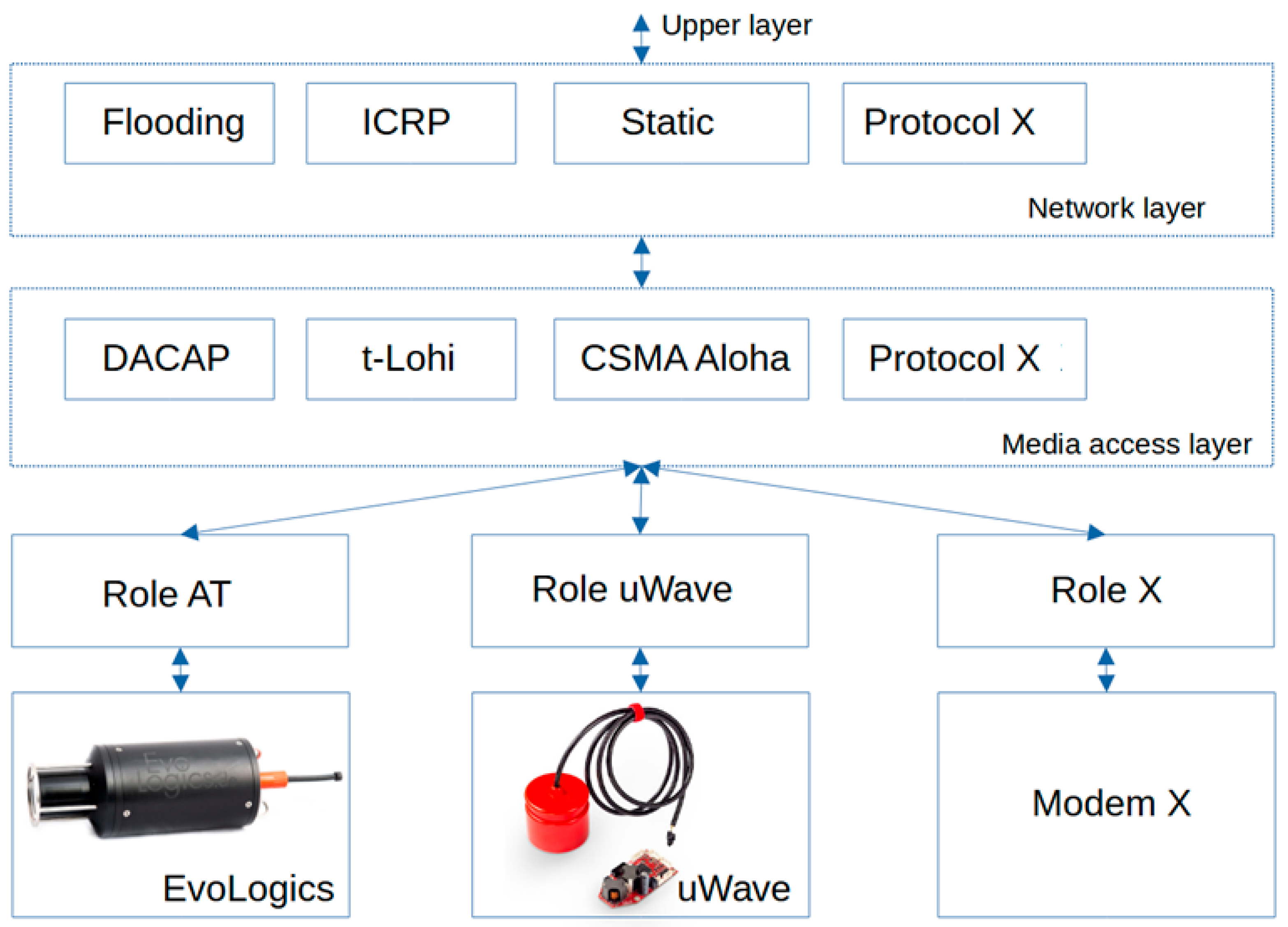
Therefore, another approach could be considered, which involves not modifying the software framework but rather adding applications to it that are inherently capable of working with multiple modems (with different roles). This is illustrated in Figure 5—in addition to or instead of the existing protocol, a protocol could be developed that works not only with the AT command role but also with roles of other commands.
This approach could significantly reduce the costs associated with expanding the capabilities of the software framework, particularly by enhancing its ability to create hydroacoustic networks based on modems from different manufacturers. In turn, this would contribute to broadening the scope of tasks related to the Internet of Things in the maritime domain.
As a part of the current project to expand the capabilities of the software framework, custom protocols for the medium access control and network layers have been developed. These protocols are capable of working with a variety of roles responsible for parsing commands from modems of different manufacturers, such as the uWave modem and the Evologics modem.
These roles enable the parsing of commands specific to the corresponding modem and convert them into the format of internal messages characteristic of EviNS applications. They also facilitate the reverse process, parsing commands from EviNS applications and converting them into the format of internal messages for the respective modem. For EviNS utilization, user application is created.
The EviNS framework source code resides on the GitHub web service, which hosts projects using the Git version control system. This platform provides extensive opportunities for the collaborative development of open-source IT projects. The link, URL: https://github.com/okebkal/evins (accessed on 5 October 2022), provides access to the directory structure where the EviNS software framework is located. For instance, the/include directory contains macros that describe the structure of a finite state machine. The/src directory houses the source code for agents that have already been created. The examples catalog includes application samples that serve as templates, helping to lower the “entry threshold” for the practical use of the EviNS software framework.
To build the EviNS software framework on a Linux PC, the user can clone the EviNS project into a directory prepared for the clone via the terminal, in particular using the command git clone, URL: https://github.com/okebkal/evins.git (accessed on 5 October 2022).
After cloning the EviNS project, you can install it using the make command from the terminal in the project’s root directory. During installation, the EviNS project also includes a list of dependencies, allowing you to install all the necessary libraries from GitHub. Once the EviNS software framework is installed, configuration is required before EviNS can be operational.
The implementation of initial network protocols can be considered as a component of the comprehensive EviNS software framework. This framework, in turn, has the potential to become a part of standard hydroacoustic modem software. Such implementation holds practical significance for establishing an underwater sensor network within Marine Internet of Things (MIoT) systems. Notably, several essential network layer protocols have already been incorporated into the EviNS software framework.
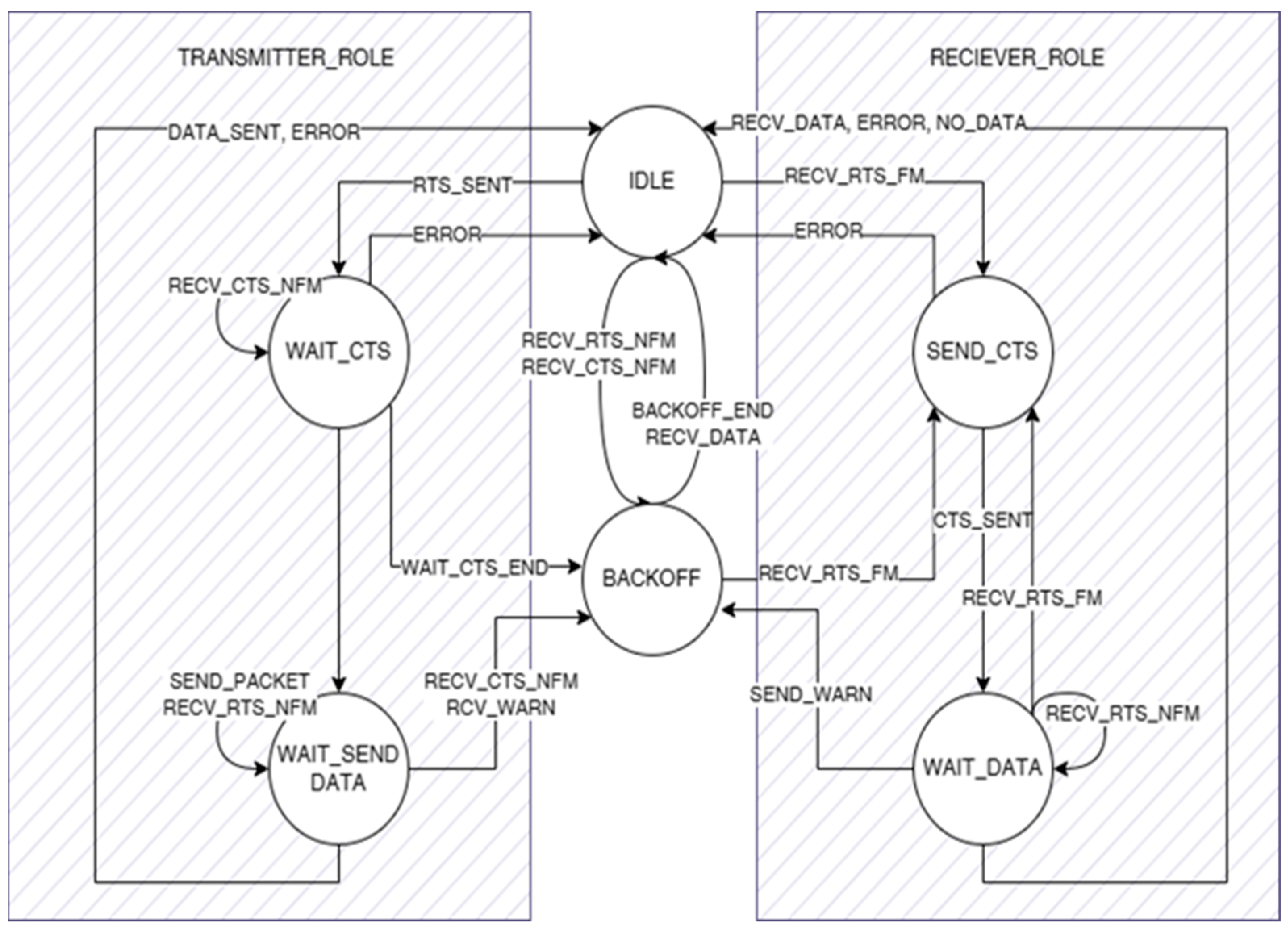
To reduce the occurrence of collisions (or even prevent them altogether), a specialized environment access control protocol variant called CSMA-Aloha has been incorporated into the EviNS software framework. Currently, this protocol is specifically designed for broadcast data packets. According to the protocol, each hydroacoustic modem “listens” to the hydroacoustic channel before transmitting its own data packet. It begins broadcasting only when there is no activity from other network participants. Each participant in the network receives information about when they can access the channel. This capability is achieved by including the protocol in each of the network nodes.
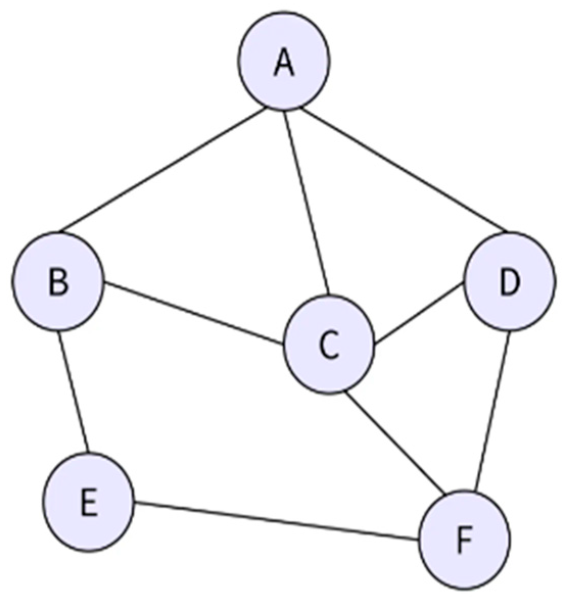
In addition to controlling access to the environment, network participants may also be interested in the location of the source or recipient of the data they plan to exchange during a data exchange session. When participants in the network are separated by a significant distance, the data sources may not have a direct connection to the data recipients. However, with sufficient connectivity within the hydroacoustic network, data transmission can occur through neighboring participants who are within a working distance from the desired data sources or recipients. These neighboring participants contribute to redirecting the data flow in the correct direction. To address this challenge, the EviNS software framework incorporates two specialized data routing protocols, i.e., static routing and avalanche routing, both of which control the number of transmitted packets.
According to the static routing protocol, each network participant is pre-assigned one of the two roles: either a relay or a passive participant. Upon receiving a data packet, the relay participant forwards it to the next address (also pre-assigned) of another relay participant, and this process continues until the data reaches its final recipient. While this protocol can be efficient in terms of energy consumption and data delivery time, it suffers from limited applicability due to the inability to alter the geometry of the hydroacoustic network after it has been deployed underwater.
The second protocol is designed for networks with rapidly changing geometries (such as those involving mobile participants like Autonomous Underwater Vehicles (AUVs)). While it may be redundant in terms of the amount of transmitted data within the network (and consequently, energy consumption), it reliably functions with any network dynamics. Under this protocol, each network participant determines the current data packet number that they have received. If a packet is not intended for them and is received for the first time, they redirect it to other network participants within their working range. This process continues until the package reaches its intended recipient.
The utilization of these protocols in practical scenarios was conducted as a part of a study in [25]. This study investigated the performance characteristics of a digital hydroacoustic network built upon these protocols, as well as the advantages and disadvantages associated with their practical use. The findings revealed that the combination of properties inherent to these protocols confers an advantage to users in networks with dynamically changing geometry—such as acoustically interconnected cooperative or coordinated groups of fast-moving AUVs. Notably, these advantages encompass minimal transmission time and the highest probability of successful data delivery to the ultimate recipient within the network. However, it is essential to acknowledge that the specific energy consumption for transmitting a unit of information within such a network is relatively high (attributable to frequent data delivery route duplication). Consequently, the autonomous operational duration of such a network remains relatively short.
In the following section, the implementation of a number of network and link layer protocols that were developed and deployed by the authors within the EviNS software framework is presented. This implementation is capable of functioning in a dynamic network. However, in cases of rapid changes in network geometry, it may struggle to adapt to the evolving connections among its mobile participants. Under this protocol, network participants periodically search for and reassign data delivery routes (for relatively short periods). During data transmission, packets are only forwarded by those participants included in the updated route and designated as relay nodes. It is expected that the use of this protocol will result in relatively low levels of excess data transmission in the network (and consequently, lower energy consumption) compared to avalanche routing. However, this protocol is not intended for use in networks with rapidly changing geometries. In other words, the presented implementation of this network-level protocol strikes a compromise between network dynamics and energy efficiency and is limited to applications where such a compromise is acceptable.
A notable aspect of the current work involves creating user applications in the form of protocols for the environment’s access control layer and network layer. These protocols are designed to interact with different roles, enabling the technical capability to connect third-party modems to the EviNS software framework. Specifically, this includes Russian-made uWAVE modems. Importantly, this example highlights another advantage of utilizing a software framework for constructing hydroacoustic networks, i.e., the ability to leverage previously developed protocol stacks within the software framework to control hydroacoustic from various manufacturers, thereby significantly enhancing their functionalities.

4. Medium Access and Network Layer Protocols

4.1. Medium Access Layer Protocols

Data transfer between two hydroacoustic modems in point-to-point (P2P) mode involves one modem connected to the data source and the second modem connected to the receiver. The transfer uses physical layer algorithms and is limited by the mutual coverage area. However, if more than two modems are within this coverage area, stable data transmission is not guaranteed due to collisions and mutual interference.
To manage multiple devices within the same coverage area, we need methods for the media access control layer (also known as the data link layer). These methods ensure the resolution of collisions between data packets.
To ensure the functioning of multiple digital hydroacoustic communication devices within the same coverage area, specialized control algorithms are being developed at the channel level of the OSI model. These algorithms consider the time dispersion and propagation delays of the hydroacoustic signal.
To enhance operational efficiency in a hydroacoustic signal propagation environment and mitigate collisions during data exchange and delivery to modems lacking synchronous operation capabilities, a data transmission algorithm was devised. This algorithm utilizes the DACAP [17] channel layer protocol, which operates asynchronously, and relies on individual connections between network nodes to minimize access time to the signal propagation environment.

4.1.1. User Implementation of Distance-Aware Collision Avoidance Protocol

The distance-aware collision avoidance protocol (DACAP) [17] is an access control protocol that operates asynchronously and is based on the acknowledgment of individual connections between modems. When exchanging data, the modem sender planning to transmit information to another modem generates a Request to Send (RTS). Upon receiving the Request to Send (RTS), the modem receiver immediately responds with a Clear to Send (CTS) and then waits for the data packet. After sending the transmission-enabling packet, if the modem receiver detects activity in the transmission medium that could lead to signal corruption, it generates a short warning signal, resulting in message transmission cessation. Following the receipt of the clearance command, the modem sender observes a brief pause. If during this pause there is activity from other modems or the modem sender receives a warning signal from the modem receiver, data transmission is canceled. The delay time for transmission depends on the distance between the source and the recipient. The waiting period is chosen to ensure the absence of harmful collisions. Consequently, the “handshake” time between nearby neighbor modems can be kept short, while between remote nodes, it needs to be longer.
To optimize network bandwidth, a predefined minimum handshake length, denoted as tmin, is established for all nodes. This mechanism facilitates efficient data transfer performance and guarantees minimal waiting time.
The waiting period is selected to prevent any detrimental collisions. Consequently, the handshake duration between proximate modems, such as those used by neighbors, can be kept brief. However, for remote nodes, it is essential to extend the handshake time.
The protocol’s overall structure is illustrated in Figure 6.
Figure 6 illustrates the state machine and transition events for a device involved in transmitting and receiving data. The left and right sides represent the states, while the center contains states relevant to both roles. The algorithm begins in the IDLE state. If there are data to send and the RTS signal was previously sent, it transitions to the WAIT_CTS state. On the receiving side, if the RTS is accepted, the device enters either the SEND_CTS or the BACKOFF state, depending on whether the data are intended for it.
The DACAP protocol relies on the packet transmission time between transmitting and receiving nodes. The priority value is determined by the distance between these nodes, and RTS/CTS “handshakes” are essential for distinguishing transmissions among nearby nodes. If a node does not participate in the transfer, it enters a “rollback” state, from which it exits either at the end of other nodes’ transfers or after reaching the waiting time interval calculated using the following formula:
T p e r = t min 2 U / C , U / c > t min min ( Δ D / c , t d a t a , 2 T t min ) 2 2 ( U + Δ D ) / c t min , U / c > t min min ( Δ D / c , t d a t a , 2 T t min ) 2 ,
where c represents the speed of sound propagation in water; U + ΔD denotes the minimum distance to the interfering node, where correct reception is still feasible; tdata signifies the data transfer rate; and tmin corresponds to the time of transmission for CTS/RTS signals. The algorithm of the DACAP protocol is presented in Appendix A, Algorithm A1.

4.1.2. User Implementation of Tone Lohi Protocol

An energy-efficient protocol called Tone Lohi (T-Lohi) [20] has been developed for an underwater acoustic network of short-range sensors [6,20]. This protocol ensures stable access to the transmission medium even under conditions of low power from the on-board transmitter and limited energy resources. The T-Lohi protocol [20] incorporates a channel redundancy mechanism to prevent message collisions during transmission. Additionally, the protocol requires specialized equipment with a wake-up function based on a tone signal. This approach effectively resolves conflicts related to channel redundancy without significantly increasing energy consumption.
The T-Lohi protocol employs specific mechanisms to transition equipment into power-saving mode and to wake up or request network resources using a distinct tonal acoustic signal. This approach can lead to substantial energy savings.
There are three distinct implementations of this protocol. ST-Lohi (Synchronized T-Lohi): this implementation prioritizes energy-efficient transmission. According to the modeling presented in the same work, the protocol achieves efficiency within 3% of the maximum value. aUT-Lohi (Aggressive Unsynchronized T-Lohi): this variant allows for the maximum bandwidth utilization among the three implementations, with a channel utilization of approximately 50%. cUT-Lohi (Conservative Unsynchronized T-Lohi): this implementation focuses on reliable data transmission with minimal loss. It ensures efficient use of the transmission medium while maintaining stable bandwidth and high energy efficiency.
The T-Lohi protocol [6] relies on the utilization of short messages (tones) to reserve a communication channel. It also permits competitive requests for channel access from other network nodes (as depicted in Figure 7). As a result, this medium access control (MAC) level protocol ensures stable bandwidth and low power consumption.
Figure 7 schematically depicts four devices: A, B, C, and D. Device B has previously allocated a channel for transmitting information and has sent packets to devices A, C, and D, effectively blocking other devices from transmitting. Consequently, only device A will have the chance to exit the Backoff/Blocking state during the third competition round and data transfer.
The protocol operates based on the following principle: when a node have data to transmit, it notifies other devices and enters the contention round (CR). Each device that receives a tone enters the “Backoff” state for a duration w, where w is a normally distributed random value within the range from 0 to the number of applicants (CTC). Consequently, the device that exits the “Backoff” state earlier or one that was not a part of it reserves the channel, initiating the next competitive round for the remaining devices.
The protocol data frame’s structure is depicted in Figure 8. Each frame comprises a backup period (RP), followed by a block of payload data. Within each RP, a series of negotiation rounds occurs until one node successfully reserves a channel.
To identify collisions and estimate the number of competitors, a collision resolution mechanism is employed, considering both spatial and temporal uncertainties as well as the significant latency in the data packet delivery.
Based on the number of incoming tones, applicants for the channel (CTC) are tallied. When the device has detected a tone, it enters the “Backoff” state for a duration of w:
W = U × CTC, where U∼Uniform (0,1).
If, after the competition round (CR) expires, the device has not entered the “Backoff” state, it reserves a channel for transmitting its data packet and exits the CR. The period between competition rounds is calculated as follows:
C R = T m a x + T t o n e ,
where T m a x is the longest packet transmission time in the environment, and T t o n e is the transmission time of a short message (tone).
The algorithm of the T-Lohi protocol is presented in Appendix A, Algorithm A2.

4.2. Network Layer Protocols

4.2.1. Flooding

Flooding is a component of routing protocols where packets are broadcasted to all nodes within the network. This behavior is known as “flooding”. In this routing mode, package delivery is ensured to be over 100%. However, if flooding is uncontrolled, each node will relay packets to all its neighboring nodes, resulting in an overwhelming number of broadcast messages and a network failure (known as a “broadcast storm”). This can severely degrade bandwidth and necessitate substantial network resources. To prevent a broadcast storm, conditional logic must be implemented.
The Dynamic Probabilistic Flooding Protocol (DPFlooding) [11] determines whether to forward a received data packet based on the current count of neighboring nodes (i.e., available connections). For each node, a probability value is generated based on this count, and the node uses this value to decide whether to transmit the last received data packet further across the network. The more “neighbors” a network node has, the less likely it is to retransmit the last received data packet. As a result of this operational logic, the volume of redundant information transmitted over the network is significantly reduced.
To prevent fatal network overflow due to re-received data packets and ensure the reliability of controlled flooding, the SNCF (Sequence Number Controlled Flooding) algorithm is employed. In SNCF, retransmitted packets are equipped with the number and address of the transmitting node within the network. Upon receiving a packet, the recipient node compares its number with the list of previously received packet numbers. Only packets with new numbers are eligible for further transmission. Since each node maintains sequence numbers and address information, the SNCF protocol appends its own sequence number and addresses to the packet. If a packet arrives at a node that already has the same packet in memory, the node promptly discards it.
RPF (Reverse Path Forwarding) is a technique that involves controlled flooding. The node forwards the packet only in the forward direction to the next node. If the packet arrives from the next node, it is sent back to the original sender.
Selective Flooding (SF) is a variant of the flooding algorithm that directs packets to routers in a single specific direction. Instead of forwarding every incoming packet across all available connections, nodes selectively transmit packets only along the lines that approximately align with the desired direction.
Preferably, the digital hydroacoustic network is a dynamic ad hoc network with a decentralized wireless self-organizing structure. In this design, user devices, especially underwater sensors or vehicles, can connect on the fly. Each network node is capable of forwarding (retransmitting) data intended for other nodes. The order of data transfer is dynamically determined based on the network’s connectivity.
Features of flooding protocols: during packet forwarding, all available routes between the source and destination are utilized for transmission; there is always a shortest route; successfully delivering data along this path results in the shortest delivery time; all nodes discovered on the network are utilized for transmission; no network-related information is needed, including topology and network load; since the network comprises all nodes connected either directly or indirectly, there is no possibility of any node being overlooked during data propagation; they are highly reliable; even if several intermediate nodes fail, data packets are still likely to reach their destinations; and relatively easy to implement and configure, as each network node can only be aware of its “neighbors”.
Appendix A (Algorithm A3) shows the algorithm for the DPFlooding protocol using controlled flooding (the network topology is shown in Figure 9).
The algorithm operates as follows: Data are transmitted from node A to node F. When a packet arrives at node A, it is forwarded to nodes D, C, and B. Node B then relays this packet to nodes E and C. Node C further sends the packet to nodes F and D. Additionally, node D forwards the packet to nodes F and C. Finally, node E transmits a packet directly to node F.

4.2.2. Information-Carrying Routing Protocol

The Information-Carrying Routing Protocol (ICRP) [22] is a routing protocol that operates by transmitting combined packets containing both service information and payload data. In this type of protocol, the service data required to establish a data delivery route are included as a part of a payload data packet. As a result, the routing and data transmission mechanism is energy-efficient and characterized by relatively short routing times. Importantly, ICRP is not dependent on the number of network participants or their relative locations, making it easily scalable for any arbitrary number of participants, regardless of spatial separation or mobility.
Finally, the ICRP is a reactive protocol designed for scalable routing and reduced network load. The routing task is performed by a small number of nodes. The sender initiates the establishment of the path. If there is no set path containing the path detection packet, the sender must transmit the message in a broadcast. Nodes that receive this message must broadcast it and save the return route. When the destination node receives this message, it is possible to obtain the full return route. All routes have timeouts, and it is necessary for the route to be detected within a certain timeout.
The ICRP assessment exposes several performance limitations. Because decisions rely on stored information, ICRP is inadequate for underwater networks where nodes are in constant motion. Another notable drawback is the necessity to broadcast packets when a node lacks a route to its destination, resulting in higher power consumption.
The ICRP protocol’s algorithm is provided in Appendix A (Algorithm A4). Each node continuously broadcasts its routing table to all neighboring nodes. Upon receiving this information from a neighbor, the node compares the received routing table with its own. The router then compares the routes in the resulting table with those in its routing table. If a new route has a better metric, it can replace the existing one. To optimize protocol operation, a generalized metric is used instead of a simple route metric, providing a more accurate characterization of the route. For routing stability, traffic can be distributed across multiple routes within a specified metric range, rather than relying solely on the lowest metric route. Based on the aforementioned metrics, a generalized Proute metric is calculated for each route, determining the best route. The following formula is used in this case:
P r o u t e = K 1 K 2 + K 2 D c r ,
where K1 and K2 are constants; Dc is the delay time; and r is reliability (the percentage of information successfully transmitted to the next node).
The constants represent the weighting factors for throughput and latency. In this scenario, the specific value of the weighting factor varies based on the type of information being transmitted across the network. For instance, interactive traffic requires lower latency, while file transfers benefit from greater bandwidth.
The route with the lowest generalized metric is the most preferred. If there are multiple routes to the same recipient, the router can transmit information along all of these routes (or some of them). The exact transfer process depends on the generalized metric of each route. For instance, if one route has a generalized metric of one and another has three, three times more data will be sent through the route with a generalized metric of one (in other words, this route will be used three times more frequently). However, only those routes whose generalized metrics fall within a certain range will be utilized.
ICRP achieves energy efficiency and low latency data delivery. It transmits routing control packages via data packets, resulting in an energy-efficient mechanism with minimal end-to-end delivery delay. Unlike traditional approaches, protocol does not rely on information about node locations. Additionally, it operates efficiently without requiring the knowledge of sensor node statuses, involving only a small subset of nodes in the routing process. As a result, ICRP is scalable and suitable for fixed, mobile, and hybrid networks.
The ICRP serves as an efficient communication tool for data exchange within a single network or between networks connected by routers that share route information. Noteworthy features include simultaneous load balancing across multiple paths and support for IPv6 connectivity, making it well suited for various applications. However, its 255-hop limit could be limiting for larger networks, and the triggered updates might introduce communication delays during network topology changes.

5. Experimental Part

5.1. The Hardware

For the development and testing of user software intended to address tasks in the field of networked communication, an emulator of modem networks was utilized, represented as an online service, providing access to a multitude of emulated modems. The user “places” them within a virtual space, thus defining the geometry of the communication network, which can be altered at any given moment or initially set as continuously evolving. For instance, this could entail the emulation of modem networks carried by AUVs. The EviNS software framework was executed on an Odroid H2 single-board computer (Figure 10).
The emulated modems adhere to a predefined message format in the form of AT Commands. All commands commence with the prefix “AT”, where “AT” signifies “Attention code”. Thus, the device receives a signal indicating that a command follows. Command symbols and/or alphanumeric values conclude the command string.
Example of a simple sent message:
AT*SEND,<length>,<destination address>,<data>,
where length is the length of payload (user information), destination address is the hydroacoustic address of a recipient, and data is the payload (user information), to work with such a message format, and a parser and a message generator are implemented and developed in the software framework. Tests are conducted for two interaction scenarios: between two modem nodes exchanging data in a P2P connection and for a group of modems interconnected within a network using network layer protocols. The network in the emulator comprises six nodes, the layout of which is depicted in Figure 11. The network nodes are positioned at distances ranging from 0.5 to 4 km from each other, with depth ranging from 14 to 15 m. The emulated modems are situated at depths of 12–13 m. Signal reception conditions are favorable, with the emulated bit error probability being 0.001. Hence, nearly all losses observed below are attributed to data packet collisions when multiple modems operate within the network.
In the tests, one of the network nodes acts as a data source, generating and sending packets to the four most distant nodes in the network at random intervals, once every 15 s for a duration of 600 s.
During protocol stack testing, the transmission of a payload array across the network occurs in the zone of indirect modem interaction (mediated). Specifically, nodes M3, M4, M2, and M1 within the network depicted in Figure 11 interact with each other.
The test packet consists of a message containing information in string format:
<n_p>,<depth>,<temp>,<volt>
where n_p is the number of transmitted packets, temp is the environment temperature, and volt is the modem operating voltage.
The total size of each packet is 20 bytes, and 50 packets are transmitted. Data exchange occurs both with and without the utilization of network protocols, and after which, the metrics that are assessed are as follows:
  • Time taken to transmit a data packet between two devices in P2P mode and across the network;
  • Probability of successful transmission of data packets between two devices in P2P mode and across the network.
Furthermore, experiments were conducted on UC&NL uWave modem units [4] (Figure 12a), with the layout scheme depicted in Figure 12c. Additionally, experiments under analogous conditions were conducted using physical (non-emulated) modem units from the company Evologics (Figure 12b). However, due to the limited number of hydroacoustic modems, testing in the physical environment was conducted only for the link layer protocols.

5.2. Testing of the Channel Layer Protocols

5.2.1. Experimental Results for P2P Connection without Protocols

Metrics for the Evologics and uWave modems, obtained under the specified conditions of sequential packet transmission from one device to another, are presented in Figure 13 and Figure 14.
As a result, the data transmission success rate is 96%, with an average transmission time of 0.15 s and an average transmission rate of 104 bytes per second. It is also noteworthy that, in physical environments, packet delivery may occur; however, the corresponding acknowledgment packet sent back to the sender may contain an irreparable number of bit errors and hence may be discarded upon reception. Furthermore, in asynchronous operation attempts of the modem units, there are instances where information transmission to one recipient from two devices occurs simultaneously, leading to packet collisions during reception and resulting in packet corruption (Figure 15 and Figure 16).
From Figure 15 and Figure 16, it is evident that out of 50 transmitted packets, only 34 were successfully received (64%). Consequently, the data transmission success rate stands at 68%, with an average transmission time of 0.28 s and an average transmission rate ranging from 98 to 130 bytes per second.
These results indicate that the collisions that occurred led to an increased load on the receiving modem, consequently resulting in packet loss.

5.2.2. Experimental Results for Connectivity Using Channel Protocols

Metrics obtained during data transmission using DACAP and T-Lohi protocols are shown in Figure 17 and Figure 18.
From Figure 17 and Figure 18, it is apparent that the data transmission success rate is 100%, with an average transmission time of 0.21 s for the DACAP protocol and 0.37 s for the T-Lohi protocol. The average transmission rate is 45 bytes per second for DACAP and 20 bytes per second for T-Lohi.
Thus, the utilization of the DACAP protocol, incorporating acknowledgments and error control, has allowed for enhanced transmission stability (success rate). However, the use of the protocol has increased the load on the bandwidth during data transmission, resulting in a stabilized average transmission rate, including packet control (retransmission) and handshaking, at a lower level (50 bytes per second). A similar situation is observed with the T-Lohi protocol, utilizing competitive cycles, albeit with a decreased transmission rate of 30 bytes per second.
Based on the presented graphs, it can be inferred that link layer protocols, operating based on delay times, facilitate more stable transmission (with a success rate close to 100%) of data in conditions of simultaneous transmission.

5.3. Experimental Results of Network Layer Protocols

In these tests, once again, a modem network emulator was utilized. For data exchange within the network, a protocol stack consisting of the flooding network protocol and the DACAP link layer protocol was employed. The schematic of data packet movement within the network is illustrated in Figure 19.
The metrics for the data transmission are shown in Figure 20. These metrics are generalized for the transmission path from node M3 to M1. Considering this, the average data transmission time amounted to 6.7 s, with an average transmission rate of 7 bytes per second.
Thus, the flooding network protocol allows for indirect packet transmission within the network through intermediate nodes. The time and the number of packets received by the end device depend on the maximum hop count of the network.
The investigation of data transmission parameters across the hydroacoustic channel revealed that the implementation of network communication protocols enables an enhancement in the probability of successful data packet exchange among the group’s devices. However, this increased probability comes at the cost of reduced communication speed due to the management of delay values during data packet transmission within the distribution environment.
This is supported by the findings from experiments carried out under the conditions specified in Section 5 of this article, involving a group of hydroacoustic modems. The transmission results depicted in Figure 19, when not utilizing the developed protocols, indicate that the average transmission rate within the network is 30–40 bits per second. However, simultaneously, the probability of successful transmission falls within the range of only 60–70%.
Figure 21 provides a summary of the baud rate information for each device, both with and without protocol.
Using the data link and network layer protocols, the probability of successful delivery of a packet with data increases to 100% (Figure 20); however, the transfer rate can decrease to 50 bits/s.
Figure 22 provides a summary of the success rate information for each device, both with and without protocol.
Therefore, the difference in reliability and speed has been verified to be approximately twofold. In summary, the EviNS software framework, incorporating underwater network communication protocols, can be effectively integrated into the concept of the Marine Internet of Things or the group management of Autonomous Underwater Vehicles (AUVs). In scenarios where communication channel reliability is crucial, such as situations where corrupted data may impact navigation information or control signals for other devices, the EviNS framework plays a vital role in preventing incorrect commands and emergency incidents.

6. Conclusions

As a result, a custom extension for the EviNS software framework has been developed to address the task of underwater acoustic communication networking. This extension includes a protocol stack at the data link layer consisting of DACAP and T-Lohi protocols, aimed at reducing or eliminating collisions by managing access delays to the propagation medium during packet transmission. Additionally, the network layer protocol stack includes DPFlooding and ICRP protocols to facilitate the formation of modem groups into a network and ensure reliable packet transmission within this network.
The testing results of the developed algorithms suggest that the use of these network and data link layer protocols increases the probability of successful packet transmission within the network (achieving 100% compared to 60–70% without protocol usage), albeit at the expense of data exchange speed (reduced from 120 bits/s to 60 bits/s for Evologics modems). This reduction in speed is attributed to the increase in average access delay to the propagation medium.
This development can be further enhanced by incorporating software modules that enable the integration of modems from various manufacturers into the software framework. Ultimately, it could be utilized in implementing concepts related to the Internet of Things in the maritime domain or in group management of autonomous unmanned underwater vehicles.

Author Contributions

Conceptualization, K.K. and A.K.; methodology, K.K., O.K. and V.K.; software, M.D., T.A. and V.K.-A.; validation, O.K.; formal analysis, V.K.; investigation, O.K., M.D. and T.A.; resources, K.K.; data curation, O.K., M.D., T.A. and V.K.-A.; writing—original draft preparation, V.K.; writing—review and editing, K.K., A.K. and V.K.; visualization, M.D.; supervision, K.K.; project administration, A.K.; funding acquisition, A.K. All authors have read and agreed to the published version of the manuscript.

Funding

This research was funded by Sevastopol State University, which provided an internal grant (ID 42-01-09/241/2022-2). The work was also supported by the Russian Ministry of Education and Science, project FEFM-2024-0015.

Institutional Review Board Statement

Not applicable.

Informed Consent Statement

Not applicable.

Data Availability Statement

The raw data supporting the conclusions of this article will be made available by the authors on request.

Acknowledgments

The authors would like to express their gratitude towards the team at Evologics in Germany for providing an open-source software framework under the GNU GPL/MIT license. The authors would like to express their gratitude towards Latena J.S.C in Russia for providing access to the hydroacoustic modem emulator (model 104).

Conflicts of Interest

The authors declare no conflicts of interest.

Appendix A

Algorithm A1: Pseudocode for DACAP protocol
1: If you received RTS signal and it’s for you then
2:  send CTS signal;
3: else set backoff state to true;
4:  while in backoff;
5:      if ack; backoff end
6:      else compute T; backoff end after T
7: When application invokes MAC send
8: if now state is backoff;
9:      if ack; backoff end
10:    else compute T; backoff end after T;
11:   else send RTS; wait to CTS
12:    if receive RTS or CTS not for you, then
13:         cancel data transmission; set backoff state and goto line 8;
14:   else transmit data; go to idle state
Algorithm A2: Pseudocode for T-Lohi protocol
1: if you receive a contention tone (CTD) while idle
2:  set blocking state to true; unset at end of current frame
3: When application invokes MAC send
4:  if blocked; wait for end of frame and attempt in next RP.
5:  else transmit contention tone; wait for end of current CR.
6:      if (contender count (CTC) > 1)
7:       Compute w uniformly from [0,CTC]; backoff w CR(s)
8:          if CTD; while in backoff
9:            set blocking state to true; unset at end of frame
10:           wait for end of frame and attempt in next RP.
11:        else backoff ends; goto line 5 and repeat contention
12:     else contender count = 1; data reservation successful
13:         transmit data; when DP ends go to idle state
Algorithm A3: Pseudocode for Flooding protocol
1: When receiving a message from another node
2: if the message has not been received previously
3: forward the message to all neighboring nodes except the one from which the message was received
4: else ignore the message
5: When sending a message
6:  send broadcast message to all neighboring nodes
7:  wait for acknowledgment from each neighboring node
8: If acknowledgment is not received from any node
9:  retransmit the message to that node
10: else complete the transmission
Algorithm A4: Pseudocode for ICRP
1: If you receive packet; analyzing
2:  if own packet; checking destimation addres
3:      if broadcast addres; transmitting packet
4:      else if next-hop addres = local addres; node is off
5:      else look for routing table
6:       if path is existed;
7:           modify the next-hop address of packet; transmitting
8:       else
9:           the next-hop address is modified as broadcast address;
10:         transmitting packet
11:  else node off; go to idle state

References

  1. Kabanov, A.; Kramar, V. Marine Internet of Things Platforms for Interoperability of Marine Robotic Agents: An Overview of Concepts and Architectures. J. Mar. Sci. Eng. 2022, 9, 1279. [Google Scholar] [CrossRef]
  2. Abreu, P.; Antonelli, G.; Arrichiello, F.; Caffaz, A.; Caiti, A.; Casalino, G.; Volpi, N.C.; de Jong, I.B.; De Palma, D.; Duarte, H.; et al. Widely Scalable Mobile Underwater Sonar Technology: An Overview of the H2020 WiMUST Project. Mar. Technol. Soc. J. 2016, 50, 42–53. [Google Scholar] [CrossRef]
  3. Ali, M.F.; Jayakody, D.N.K.; Chursin, Y.A.; Affes, S.; Dmitry, S. Recent Advances and Future Directions on Underwater Wireless Communications. Arch. Comput. Methods Eng. 2020, 27, 1379–1412. [Google Scholar] [CrossRef]
  4. Dikarev, A. Position Estimation of Autonomous Underwater Sensors Using the Virtual Long Baseline Method. Int. J. Wirel. Mob. Netw. 2019, 11, 13–25. [Google Scholar] [CrossRef]
  5. Chitre, M.; Bhatnagar, R.; Soh, W.-S. UnetStack: An agent-based software stack and simulator for underwater networks. In Proceedings of the 2014 Oceans—St. John’s, OCEANS 2014, St. John’s, NL, Canada, 14–19 September 2014. [Google Scholar] [CrossRef]
  6. Shah, S.M.; Sun, Z.; Zaman, K.; Hussain, A.; Ullah, I.; Ghadi, Y.Y.; Khan, M.A.; Nasimov, R. Advancements in Neighboring-Based Energy-Efficient Routing Protocol (NBEER) for Underwater Wireless Sensor Networks. Sensors 2023, 23, 6025. [Google Scholar] [CrossRef] [PubMed]
  7. Heidemann, J.; Stojanovic, M.; Zorzi, M. Underwater sensor networks: Applications, advances and challenges. Philos. Trans. R. Soc. A Math. Phys. Eng. Sci. 2012, 370, 158–175. [Google Scholar] [CrossRef] [PubMed]
  8. Schirripa Spagnolo, G.; Cozzella, L.; Leccese, F. Underwater Optical Wireless Communications: Overview. Sensors 2020, 20, 2261. [Google Scholar] [CrossRef] [PubMed]
  9. Islam, K.Y.; Ahmad, I.; Habibi, D.; Zahed, M.I.A.; Kamruzzaman, J. Green Underwater Wireless Communications Using Hybrid Optical-Acoustic Technologies. IEEE Access 2021, 9, 85109–85123. [Google Scholar] [CrossRef]
  10. Gupta, S.; Singh, N.P. Underwater wireless sensor networks: A review of routing protocols, taxonomy, and future directions. J. Supercomput. 2023, 80, 5163–5196. [Google Scholar] [CrossRef]
  11. Hanashi, A.M.; Algoul, S. The Effectiveness of Dynamic Probabilistic Flooding in On-Demand Routing Protocols for MANETs was Assessed through a Performance Analysis. Eur. J. Theor. Appl. Sci. 2023, 1, 935–941. [Google Scholar] [CrossRef] [PubMed]
  12. ISO/IEC 30140-1:2018; Information Technology—Underwater Acoustic Sensor Network (UWASN)—Part 1: Overview and Requirements. ISO: Geneva, Switzerland, 2018.
  13. Leonov, A.; Naniy, O.; Treshikov, V. Improving modulation formats in dwdm optical communication systems. LAST MILE Russia 2019, 8, 30–36. [Google Scholar]
  14. Petrioli, C.; Petroccia, R.; Potter, J.R.; Spaccini, D. The SUNSET framework for simulation, emulation and at-sea testing of underwater wireless sensor networks. Ad Hoc Netw. 2015, 34, 224–238. [Google Scholar] [CrossRef]
  15. Sasson, Y.; Cavin, D.; Schiper, A. Probabilistic broadcast for flooding in wireless mobile ad hoc networks. In Proceedings of the 2003 IEEE Wireless Communications and Networking, New Orleans, LA, USA, 16–20 March 2003; Volume 2, pp. 1124–1130. [Google Scholar] [CrossRef]
  16. Liu, C. Distributed Databases Synchronization in Named Data Delay Tolerant Networks. Master’s Thesis, Department of Informatics, University of MINHO, Braga, Portugal, October 2016. [Google Scholar]
  17. Peleato, B.; Stojanovic, M. Distance aware collision avoidance protocol for ad-hoc underwater acoustic sensor networks. IEEE Commun. Lett. 2007, 11, 1025–1027. [Google Scholar] [CrossRef]
  18. Petrioli, C.; Petroccia, R.; Stojanovic, M. A comparative performance evaluation of MAC protocols for underwater sensor networks. In Proceedings of the OCEANS 2008, Quebec City, QC, Canada, 15–18 September 2008; pp. 1–10. [Google Scholar] [CrossRef]
  19. Syed, A.A.; Ye, W.; Heidemann, J. T-Lohi: A New Class of MAC Protocols for Underwater Acoustic Sensor Networks. In Proceedings of the IEEE INFOCOM 2008—The 27th Conference on Computer Communications, Phoenix, AZ, USA, 13–18 April 2008; pp. 231–235. [Google Scholar] [CrossRef]
  20. Syed, A.A.; Ye, W.; Heidemann, J. Comparison and Evaluation of the T-Lohi MAC for Underwater Acoustic Sensor Networks. IEEE J. Sel. Areas Commun. 2008, 26, 1731–1743. [Google Scholar] [CrossRef]
  21. Abu Zant, M.; Yasin, A. Avoiding and Isolating Flooding Attack by Enhancing AODV MANET Protocol (AIF_AODV). Secur. Commun. Netw. 2019, 2019, 8249108. [Google Scholar] [CrossRef]
  22. Liang, W. Information-Carrying Based Routing Protocol for Underwater Acoustic Sensor Network. In Proceedings of the 2007 International Conference on Mechatronics and Automation, Harbin, China, 5–8 August 2007; pp. 729–734. [Google Scholar] [CrossRef]
  23. Masiero, R.; Azad, S.; Favaro, F.; Petrani, M.; Toso, G.; Guerra, F.; Casari, P.; Zorzi, M. DESERT Underwater: An NSMiraclebased framework to DEsign, Simulate, Emulate and Realize Testbeds for Underwater network protocols. In Proceedings of the IEEE/OES Oceans, Yeosu, Republic of Korea, 21–24 May 2012. [Google Scholar] [CrossRef]
  24. Kebkal, O.; Kebkal, V.; Kebkal, K. EviNS: Framework for development of underwater acoustic sensor networks and positioning systems. In Proceedings of the OCEANS 2015, Genova, Italy, 18–21 May 2015. [Google Scholar] [CrossRef]
  25. Kebkal, K.G.; Kebkal, V.K.; Minaev, D.D.; Leonenkov, R.V.; Korytko, A.S. An Underwater Digital Network on Acoustic Modems with EviNS Framework: A Case Study. Gyroscopy Navig. 2018, 9, 325–333. [Google Scholar] [CrossRef]
Figure 1. The architecture of the EviNS software framework.
Applsci 14 03527 g001
Figure 2. Process structuring model—interaction of workflows and supervisors.
Applsci 14 03527 g002
Figure 3. Types of interfaces used in the EviNS software framework.
Applsci 14 03527 g003
Figure 4. The structure of the interaction of hydroacoustic modems with the Evans (v2021) software framework in its current version.
Applsci 14 03527 g004
Figure 5. The structure of the interaction of hydroacoustic modems with the software framework, taking into account the change in the approach to the development of its protocols.
Applsci 14 03527 g005
Figure 6. DACAP finite state machine.
Applsci 14 03527 g006
Figure 7. The operating principles of the T-Lohi.
Applsci 14 03527 g007
Figure 8. The structure of the T-Lohi protocol frame.
Applsci 14 03527 g008
Figure 9. The network topology.
Applsci 14 03527 g009
Figure 10. A single-board computer with installed EviNS.
Applsci 14 03527 g010
Figure 11. The network topology.
Applsci 14 03527 g011
Figure 12. Testing equipment: (a) UC&NL uWave hydroacoustic modems; (b) Evologics S2C1834 hydroacoustic modems; and (c) uWave modems under experimental conditions (submerged in a pool filled with water).
Applsci 14 03527 g012
Figure 13. Metrics from P2P transmissions for Evologics modems.
Applsci 14 03527 g013
Figure 14. Metrics from P2P transmissions for uWave modems.
Applsci 14 03527 g014
Figure 15. Metrics for transmission from two modems to one for Evologics modems.
Applsci 14 03527 g015
Figure 16. Metrics for transmission from two modems to one for uWave modems.
Applsci 14 03527 g016
Figure 17. Metrics for the DACAP protocol for uWave modems.
Applsci 14 03527 g017
Figure 18. Metrics for the T-Lohi protocol for uWave modems.
Applsci 14 03527 g018
Figure 19. Packet transmission ordering within the network (the orange arrows indicate packets sent by node M3, the green arrows indicate packets sent by node M2, and the blue arrows indicate packets sent by node M1).
Applsci 14 03527 g019
Figure 20. Indicators for data transfer between various LATENA devices on the network (blue—device 1, green—device 2, orange—device 3, and yellow—device 4).
Applsci 14 03527 g020
Figure 21. The packet transmission rates using underwater communication protocols and without protocols.
Applsci 14 03527 g021
Figure 22. The probability of successful transmission of a packet within a network using network communication protocols and without such protocols.
Applsci 14 03527 g022
Disclaimer/Publisher’s Note: The statements, opinions and data contained in all publications are solely those of the individual author(s) and contributor(s) and not of MDPI and/or the editor(s). MDPI and/or the editor(s) disclaim responsibility for any injury to people or property resulting from any ideas, methods, instructions or products referred to in the content.

