
Research on the Autonomous Control Technology Used in the Slurry Mixing System of Cementing Units
by
 and
and
Xiang Gao
1,
Guojian Hou
2,3,
Huiwen Yang
4,
Changmiao Hu
2,3,
Junguo Cui
2,3,* and
Wensheng Xiao
2,3 1
Wanhua Chemical Group Co., Ltd., Yantai 264006, China
2
College of Mechanical and Electrical Engineering, China University of Petroleum, Qingdao 266580, China
3
National Engineering Research Center of Marine Geophysical Prospecting and Exploration and Development Equipment, Qingdao 266580, China
4
Cosco Shipping Heavy Industry Co., Ltd., Shanghai 200135, China
*
Author to whom correspondence should be addressed.
Appl. Sci. 2024, 14(9), 3568; https://doi.org/10.3390/app14093568
Submission received: 6 March 2024
/
Revised: 17 April 2024
/
Accepted: 20 April 2024
/
Published: 24 April 2024
(This article belongs to the Topic Petroleum and Gas Engineering)
Abstract
:Cementing is a critical link in oil and gas exploitation, in which slurry density control is particularly important. In this study, we examined a slurry mixing control system in order to solve the problem of time delays in the mixing system. The model of a slurry mixing system was built in accordance with the system’s structure. A Smith fuzzy PID (proportion integration differentiation) composite control solution is proposed herein, and the simulation results show that the adjustment time and overshoot are lower than those of the conventional PID control and Smith predictive compensation control. A genetic algorithm is utilized to optimize the quantization factor and scale factor of the Smith fuzzy PID controller. Following optimization, the rise time of the controller was found to be 0.45 s, which represents a decrease of 35.9%, the overshoot was reduced by 0.4%, and the stabilization time was reduced by 36.6%. Afterward, we built a cementing slurry mixing simulation experimental platform, and experiments were used to verify the feasibility and superiority of the Smith fuzzy PID controller optimized by the genetic algorithm in comparison with the conventional controllers. The study results thus provide a scientific basis for the engineering application of the autonomous control technology of the slurry mixing system in cementing units.
1. Introduction
There is an urgent need to optimize and improve existing cementing technology, such as the development of more high-end cementing equipment and advanced technology, so as to promote the development of the industry in the direction of intelligence, automation, and diversification; ensure the smooth and efficient progress of oilfield development; and improve cementing quality. Cementing is a critical link in oil and gas exploitation. As cement slurry must be pumped into a well before it begins to cure and the fact that it must cure quickly once it is in place, the control of cement slurry density is thus particularly important in this field. However, there is a time delay during the slurry mixing control process, and it is not possible for the controller to acquire an immediate response after signals are sent out. Therefore, it is of great significance to eliminate the adverse effects of time delays and achieve the rapid response of density control to improve the efficiency, safety, and reliability of cementing operations [1].
With the intense development of adaptive control at present, schemes that combine conventional controls with adaptive control are routinely adopted for time-delay systems. Adaptive control can be divided into two forms: self-tuning control and model reference adaptive control [2]. Bai J.B. et al. designed a self-tuning control scheme with Smith predictive control as the core, with it realizing online identification of the system model and thus realizing compensation for the system [3]. With the development of intelligent control, in their study, Mohamed A. R. S. et al. used particle swarm optimization to optimize the parameters of the fuzzy controller and improve the dynamic performance of the controller [4]. Gao J. et al. proposed a main steam pressure control technology based on a mismatch compensation Smith RBF (radial basis function) neural network, which was found to be satisfactory in terms of stability and anti-interference ability [5]. Ning X. Z. et al. achieved multi-objective optimization of Smith prediction model parameters, effectively overcoming the nonlinearity of the system [6]. Wang J.S. proposed a PID Smith control algorithm based on particle swarm and verified that the controller had strong robustness and adaptability [7]. Liang H.B. et al. proposed an improved genetic algorithm-optimized fuzzy controller and proved that the system’s rapidity and stability were improved following optimization [8]. Wang Y.T. et al. used PSO to optimize a water and fertilizer device based on Smith fuzzy PID control, and the optimized system was found to have a faster response speed and higher accuracy [9].
In one study, a neural network was introduced to optimize the gain of the PID controller and reduce the adjustment time and steady-state error [10]. In another study, a multi-layer controller was designed to improve the learning ability and flexibility of a fuzzy neural network, and the authors conducted simulation and verification of the controller [11]. In a different study, a class of self-organizing intelligent controllers (SOICs) for nonlinear systems was proposed, the structure and parameters of the SOICs were updated by an adaptive projection algorithm, and the superior control performance of the SOICs was verified [12]. The authors of another study improved the fuzzy self-tuning PID (FA-PID) method based on the rate of change, and the adjusted control parameters were calculated according to the predicted output of the control system. The authors verified the performance of the controller, such as its fast control speed, strong anti-interference ability, limited overshoot, and small steady-state error [13]. The authors then proposed a fault diagnosis framework for autonomous vehicles based on hybrid data analysis and fuzzy proportional–integral–derivative (PID) control. The effectiveness of the proposed method in the fault diagnosis framework was also verified through the use of experiments and simulations [14].
Conventional methods for PID controller parameter tuning require an accurate mathematical model of the controlled object, whereas fuzzy control and neural networks have strong adaptive and self-learning capabilities. The genetic algorithm is a new global optimization method that can be used to design adaptive PID intelligent controllers based on fuzzy neural networks and GAs (genetic algorithms) [15]. PID controllers can be optimized through the use of PSO (particle swarm optimization) algorithms for better control [16]. Fuzzy-dependent adjustable matrix methods are more flexible than some conventional estimation techniques that use deterministic constant matrices [17]. The adaptive neuro-fuzzy PID controller based on the double-delayed deep deterministic policy gradient algorithm combines the advantages of FIS and PID control and can realize the automatic adjustment of the fuzzy PID controller gain [18]. In the actual control system, any actual physical system is strictly nonlinear, and the linear control theory is widely used to analyze and study the system [19,20]. Linear systems can only describe single-input–single-output stationary systems and have difficulty in contending with multiple-input–multiple-output systems. A nonlinear system can aid in obtaining the optimal control strategy according to the system model and control objectives. The firmness of the connection between the cement paste and the well wall directly determines the life and production of the oil and gas well; therefore, the monitoring and control technology used to assess the density of the cement paste is particularly important. Materials such as cement paste concrete can be controlled by artificial intelligence; in contrast, the concrete structure and materials can be monitored acoustically [21,22]. High-precision and high-efficiency control can be realized through the use of the above methods.
In this study, we established a system model by analyzing the principle of the cement slurry density control process. A composite control strategy combining PID control, Smith predictive compensation control, and fuzzy control was adopted to solve the problem of time delays in the control process, and a genetic algorithm was used to optimize the quantization factor and scale factor of the fuzzy controller. Compared with the control scheme before optimization and conventional control methods, the system has a faster response speed and higher control accuracy, which can better meet the control requirements of time-delay systems.
2. Working Principle and Model Establishment of the Slurry Mixing System
2.1. Working Principle of the Slurry Mixing System
Figure 1 shows the structure of the automatic slurry mixing system of cementing units. The slurry mixing system includes a water pump, a water flowmeter, a mixing tank, a mechanical agitator, a recirculating pump, a densitometer, an averaging tank, and a boost pump. The automatic mixing system ensures the quality and efficiency of the cement mixing process.
The water pump is used to pump water to the slurry mixing tank. The water flowmeter is used to measure the water flow rate and send the flow rate signal to the controller. The shape of the slurry mixing tank is subject to the specific configuration of the cementing unit, and it is used to store the cement slurry temporarily and provide proper space for mixing water and dry cement together so as to mix cement slurry of uniform density. The agitator is mainly used to stir the slurry in the slurry mixing tank to ensure that the dry cement and water are fully mixed to produce high-quality slurry. The recirculating pump removes the slurry from the slurry mixing tank to recirculate the slurry for secondary and multiple mixing of the slurry. At the same time, the slurry re-enters the mixing tank after passing through the densitometer in the branch pipe. The densitometer is used to monitor the slurry density in real time and send the density signal to the controller. The averaging tank is able to make the slurry more uniform, improving the quality of the slurry further. The boost pump is used to pressurize the slurry from the slurry mixing tank and then pump it to the suction manifold of the triplex plunger pump.
The speed, stability, and anti-interference ability of cement slurry density control in the cementing process reflect the control performance of the control system, and the set density value of cement slurry can be adjusted at any time according to the specific working conditions of downhole cementing. When the set density changes during operation, it is equivalent to the step response, which requires that the slurry mixing control algorithm can immediately respond to the adjustment, and the controller can act quickly to output the cement slurry that meets the requirements. The specific control process is as follows: the water flow sensor detects the water flow and feeds the data back to the computer, and the computer calculates the valve position of the lower gray valve through the water flow; as long as the water flow changes, the lower grey valve will respond accordingly; the controller reads the density measured by the densitometer, and the control algorithm combines the set density with the actual density to calculate the new value of the valve position of the lower gray valve and adjusts the valve opening degree. At this point, if the density of the lower gray valve changes, the control algorithm will respond immediately to adjust the valve position degree; at this point, if there is a certain degree of deviation in the lower ash valve position, the feedback control loop begins to act so that the deviation reaches its minimum.
The automatic control system in the specific operation process may encounter hysteresis problems; the mixing tank mixing cement slurry density and triplex plunger pump discharge cement slurry density cannot be synchronously changed; there will be a specified lag time difference. In order to avoid the above problems, there is a need for changes to occur in the system. When the density of the change in the computer is based on the actual situation of rapid output, the lower gray valve position quickly changes to reduce the mixing slurry obtained from the root tank cement slurry density reaction time difference. Figure 2 shows the principle of the automatic control system.
2.2. Establishment of the Slurry Mixing System Model
In order to achieve precise control of cement slurry density, a set of automatic control systems that can timely and accurately adjust and control the size of the electromagnetic proportional valve have become the key components of cementing slurry mixing systems; therefore, it is necessary to establish a mathematical model for electromagnetic proportional valves.
- (1)
- Proportional amplifier
The proportional amplifier is a component that provides a specific current to the solenoid valve, and it has a significant influence on the performance of the entire density control system. When the proportional amplifier is operating, it receives a weak control electrical signal and proportionally outputs the current required by the operation of the control solenoid valve. The proportional amplifier is generally a proportional element, and the transfer function is shown in Equation (1).
where I(s) represents the input current of the proportional amplifier, A; U(s) represents the analog voltage that the digital controller converts into, V; and Ka represents the gain of the proportional amplifier, A/V.
- (2)
- Solenoid proportional valve
The proportional amplifier outputs the current to act on the valve actuator; then, the valve openness is changed under the action of electromagnetic force, and the gas flow of each throttle is regulated. Namely, the input of the solenoid valve is the control current, and the output is the openness of the valve.
If the electromagnetic actuation force of a solenoid proportional valve is Fem, its expression is as follows:
where xev is the effective movement of the proportional valve core, m; i is the current passing through the coil of the proportional valve, A; N is the number of coils of coil inductance; and G is the air gap permeability.
On the control coil of the solenoid proportional valve, the relationship between the input coil voltage u and the current through the coil i is given by Equation (3):
where R1 is the internal resistance of the coil, Ω; R2 is the internal resistance of the electric controller, Ω; L is the coil inductance, H; and Ksi is the coefficient of self-inductance electromotive force, H.
The force on the valve core inside the solenoid proportional valves is balanced, and the displacement motion equation of the valve core can be obtained by using Newton’s second law. The equation is as follows:
where m is the mass of the core, kg; c is the damping coefficient; Ks is the stiffness of the zero spring, N/mm; and Fxev is the steady-state flow force, N.
According to the analysis above, ignoring the internal and external leakage and taking the voltage signal u of the solenoid proportional valves as the input and the linear effective displacement xev of the valve core as the output, the transfer function of the solenoid proportional valves can be expressed as:
After the proportional amplifier is introduced, the overall transfer function of the system is:
3. Design of the Slurry Mixing System Controller
3.1. Design of the Smith Fuzzy PID Controller
The conventional PID control and the typical Smith predictive compensation algorithm for the time-delay system still have limitations in terms of the control of the slurry density time-delay system. Therefore, a composite control strategy combining PID control, Smith predictive compensation control, and fuzzy control is proposed, namely Smith fuzzy PID control.
In practical applications, the principle of the Smith fuzzy PID control scheme is shown in Figure 3, in which the design of the fuzzy controller mainly includes three processes: fuzzification, fuzzy inference, and defuzzification [23].
- (1)
- Fuzzification
The input of the fuzzy controller is the difference e between the measured density of the densitometer and the set density, and the change rate ec of the difference between the measured density and the set density. The output is the correction values ΔKp, ΔKi, and ΔKd of the PID parameters. In this paper, the domain of discourse of input and output variables is described as the set {NB,NM,NS,ZO,PS,PM,PB}. The domain of discourse range of each input and output variable is shown in Table 1.
According to the characteristics of the slurry mixing control system, the input and output of the system using a combination of linear trigonometric functions and Gaussian functions to describe the membership function, in which the Gaussian function is selected on both sides and the trigonometric function is selected in the middle. Through the fuzzy control design toolbox of MATLAB R2023a, the types and parameters of input and output membership functions of the system can be designed, and the input membership function, as shown in Figure 4, and the output membership function, as shown in Figure 5, can be obtained.
- (2)
- Fuzzy Inference
In this paper, for the design of the fuzzy controller, we adopted the Mamdani type as a fuzzy reasoning method. Based on understanding the influence of each parameter on the dynamic characteristics of the system, the system combines expert experience, draws lessons from the control rules adopted by other similar fuzzy control systems for controlled objects, and adopts the construction of “if...then...”. The relationship between the input state quantity (e and ec) and the control variable (ΔKp, ΔKi, and ΔKd) is established in the form of the rule control statement. A total of 49 control rules are established, and the specific control rules are expressed by the fuzzy inferences in Table 2 and Table 3.
- (3)
- Defuzzification
What is obtained through fuzzy inference is a fuzzy quantity, and defuzzification is the process of converting the abstract results obtained by fuzzy inference into precise values that can be recognized by the actuator through the use of various methods. There are a number of defuzzification methods, and the applicable calculation method should be reasonably selected according to the control requirements of the density control system. Commonly used methods include the maximum membership degree method, the center of gravity method, and the weighted fuzzy mean method. The center of gravity method can respond to the input signal even if the input signal changes ever so slightly and has the characteristics of precise values and high accuracy. In light of the above, the center of gravity method was used for the defuzzification process described herein.
After the precise ΔKp, ΔKi, and ΔKd are obtained, tuning should also be combined with the actual PID parameters. The tuning expression is as follows:
where Kxo is the initial value of each PID parameter; kx is the quantization factor; and ΔKx is the correction value after defuzzification.
Relative parameters of the system are modified by fuzzy control, which successfully overcomes the shortcomings of the system, such as low control accuracy and poor stability.
3.2. Control Algorithm Simulation
In the previous section, we detailed how the adaptive fuzzy PID controller was designed by analyzing the density control system. In this section, the controller model was built using Simulink, and simulation experiments were conducted. The comprehensive simulation of PID control, Smith control, and Smith fuzzy PID control was carried out using Simulink. Specifically, the PID control function was realized first; based on PID control, a compensation loop was introduced in parallel to form Smith control on the controller, and then, the Fuzzy logic control module was added to access the set fuzzy controller to achieve the Smith fuzzy PID function. The three control schemes output response images from the same oscilloscope. The controller wiring diagram built using Simulink is shown in Figure 6, and the internal structure of the fuzzy controller is shown in Figure 7.
The input of the system was set as a step signal with an amplitude of one, the simulation time was 20 s, and the three initial parameters of the PID were Kp = 1000, Ki = 4, and Kd = 20. Through simulation analysis, it was found that there were significant differences in the response curves of the slurry density control system using conventional PID control, Smith predictive compensation control, and Smith fuzzy PID control under the condition that the PID parameters remain unchanged. The simulation results are shown in Figure 7.
We set the input of the system to be a step signal with an amplitude of 1, the simulation time to be 20 s, and the three initial parameters of the PID to be Kp = 1000, Ki = 4, Kd = 20. It was found through the simulation analysis that, while keeping the PID parameters the same, the response curves of the slurry density control system obtained from conventional PID control, Smith predictive compensation control, and Smith fuzzy PID control were significantly different from each other. The simulation results are shown in Figure 8.
The dynamic simulation of the control system was performed using Simulink, and the simulation curves of conventional PID control, Smith predictive compensation control, and Smith fuzzy PID control were compared and analyzed. The following conclusions were drawn:
- (1)
- The conventional PID controller has a large overshoot and a long adjustment time.
- (2)
- Compared with the conventional PID control, Smith predictive compensation control does not have any overshoot, and the stability of the system is greatly improved. In addition, the rise time is shorter, and it can reach a stable state faster.
- (3)
- By adding fuzzy control on the basis of Smith prediction compensation, the system response time is shortened, the response speed is significantly improved, and the response capacity of the control system is stronger.
Through the comparison of three different control schemes, a control scheme suitable for the large delay of the cementing mixing system was found, that is, Smith fuzzy PID control was introduced into Smith predictive compensation control. This control method can shorten the rise time of the system, allow stability to be reached rapidly, and effectively eliminate the oscillation and overshoot caused by the hysteretic link of the system, and it does not produce steady-state error after stability, obtaining a satisfactory control effect and greatly improving the overall performance of the system.
4. Optimization of the Slurry Mixing System Control Scheme
4.1. The Genetic Algorithm Used to Optimize the Slurry Mixing System
A fuzzy controller is one type of method widely used in control systems; however, its optimization design process often faces problems such as a large search space, numerous parameters, high complexity, and discontinuity. A genetic algorithm is a global search algorithm, and it can overcome the above problems due to its multi-objective and highly adaptive characteristics [24].
At present, when a genetic algorithm is applied to optimize fuzzy controllers, there are mainly three optimization schemes employed: individual optimization, pairwise optimization, and simultaneous optimization [25]. However, considering the calculation costs involved, the individual optimization scheme was taken to optimize the quantization factor and scale factor in this study.
The process of genetic algorithm optimization involves the optimization of the quantization factors Ke and Kec and the scale factors PKp, PKi, and PKd of the fuzzy controller. The Smith fuzzy PID control principle optimized by the genetic algorithm is shown in Figure 9.
When a genetic algorithm is used to optimize the fuzzy controller, it is necessary to encode the quantization factor and scale factor, determine the fitness function, carry out genetic operations, such as chromosome replication, crossover, and mutation, and then achieve specified algebra or other termination conditions to obtain the population with the best fitness. The optimal individual in the population is the optimal solution to optimize the quantization factor and scale factor of the fuzzy controller. The specific implementation process of optimizing the fuzzy controller using the genetic algorithm is shown in Figure 10.
4.2. Simulation of the Control Algorithm
The Smith fuzzy PID controller model was built according to the design scheme of the Smith fuzzy PID controller optimized by the genetic algorithm proposed above, and the functions of the controller were realized using MATLAB. The Simulink wiring diagram is shown in Figure 11.
The same simulation time and input values were used to simulate the slurry density system controlled by conventional PID control, Smith predictive compensation control, Smith fuzzy PID control, and the Smith fuzzy PID controller optimized by the genetic algorithm, and the disturbance source was introduced simultaneously. The adaptation of the genetic algorithm reflects the error, overshoot, and adjustment time of the system. The adaptation curve is shown in Figure 12, and the simulation results of the four control methods are shown in Figure 13.
It can be seen from the simulation results that when contending with interference, the system under the conventional PID controller produces certain oscillations, the adjustment time is the longest time measured, and the anti-interference ability is weak. Compared with conventional PID control, the control time of the Smith predictive controller is relatively stable; however, the response time is still longer. The response of the Smith fuzzy PID controller is more stable, the adjustment time is further reduced, and the control effect is more satisfactory. The Smith fuzzy PID controller optimized by the genetic algorithm has the shortest stability time and can still show better processing performance, a faster response speed, and a shorter stability time in the case of interference. It is therefore the best control scheme for the slurry density control system.
Summarizing the output characteristics of the conventional PID control, Smith predictive compensation control, Smith fuzzy PID control, and Smith fuzzy PID controller optimized by the genetic algorithm under step signals, we quantified the system performance indexes, as shown in Table 3.
By analyzing the output curves of the four controllers and the system performance indexes, the following conclusions can be drawn:
- (1)
- The conventional PID controller has a large overshoot, poor system stability, a long adjustment time, and poor anti-interference ability.
- (2)
- The Smith predictive compensation control has a smoother curve, and it shows almost no obvious fluctuations and oscillations. Concurrently, it has a shorter rise time and can reach a stable state relatively faster; however, the response time is long.
- (3)
- Regarding the Smith fuzzy PID control, the rise time is about 0.7 s, which means that it can reach the steady state quickly, and the overshoot is very small, measuring at around 0.32%, and the anti-interference ability is improved compared with the previous two methods.
- (4)
- Regarding the GA Smith fuzzy PID control, the rise time is the shortest, around 0.3 s, the response speed is extremely fast, and its anti-interference ability is strong. Concurrently, the overshoot of the system is small and there is no steady-state error; therefore, the stability and dynamic performance of the system are better.
After comparing the four different control schemes, the Smith fuzzy PID control optimized by the genetic algorithm was selected as the control scheme for the slurry mixing time-delay system. This scheme achieved the shortest rise time, with the system therefore being able to reach stability quickly. In addition, it effectively eliminates the oscillation and overshoot caused by the time delays of the system and it will not generate steady-state errors after stabilization, which greatly improves the overall performance of the system.
5. Experimental Verification
5.1. Experimental Principle
According to the working principle of the slurry density control system, the principle diagram of this experiment is as shown in Figure 14.
During the actual experimental process, the system was simplified due to the limitations posed by the laboratory conditions. Thereafter, the equipment and materials used in the experiments primarily included the densitometer, the water flowmeter, the slurry mixing tank, the recirculating pump, cement, water, the PLC, the valves, and the pipes. The side-mounted density meter was mainly used for the online density measurement of the mixture, the PLC was mainly used for the calculation, storage, and command control of the parameters in the experiment, and the water flow meter was mainly used for the measurement of the volume flow of the conductive medium in the experiment. The accuracy of the used densitometer is 0.001 g/cm3. All components were assembled in accordance with the schematic diagram displayed herein. The experimental platform is shown in Figure 15.
5.2. Experimental Procedures
The following procedures were utilized during the experiment:
- (1)
- We checked to ensure that all components were normal and then started the water pump to add water to the slurry mixing tank.
- (2)
- We started the recirculating pump, turned on the densitometer, and supplied cement to the slurry mixing tank via gravity.
- (3)
- We confirmed that the density of the cement slurry rose slowly after the cement entered the slurry mixing tank. When the density approached the set density, we adjusted the proportional valve to control the water flow rate.
- (4)
- We continued the mixing process, transferred the densitometer data to the PLC, and adjusted the proportional valve through the slurry mixing autonomous control system to finally adjust the slurry density to the design value.
- (5)
- We observed the controller output in real time during the experimental process. Thereafter, we checked the valve openness indicator dial and recorded the valve openness.
- (6)
- We performed the experiment twice, using one controller for slurry mixing density control each time, and compared and analyzed the experimental results.
5.3. Experimental Data Recording and Analysis
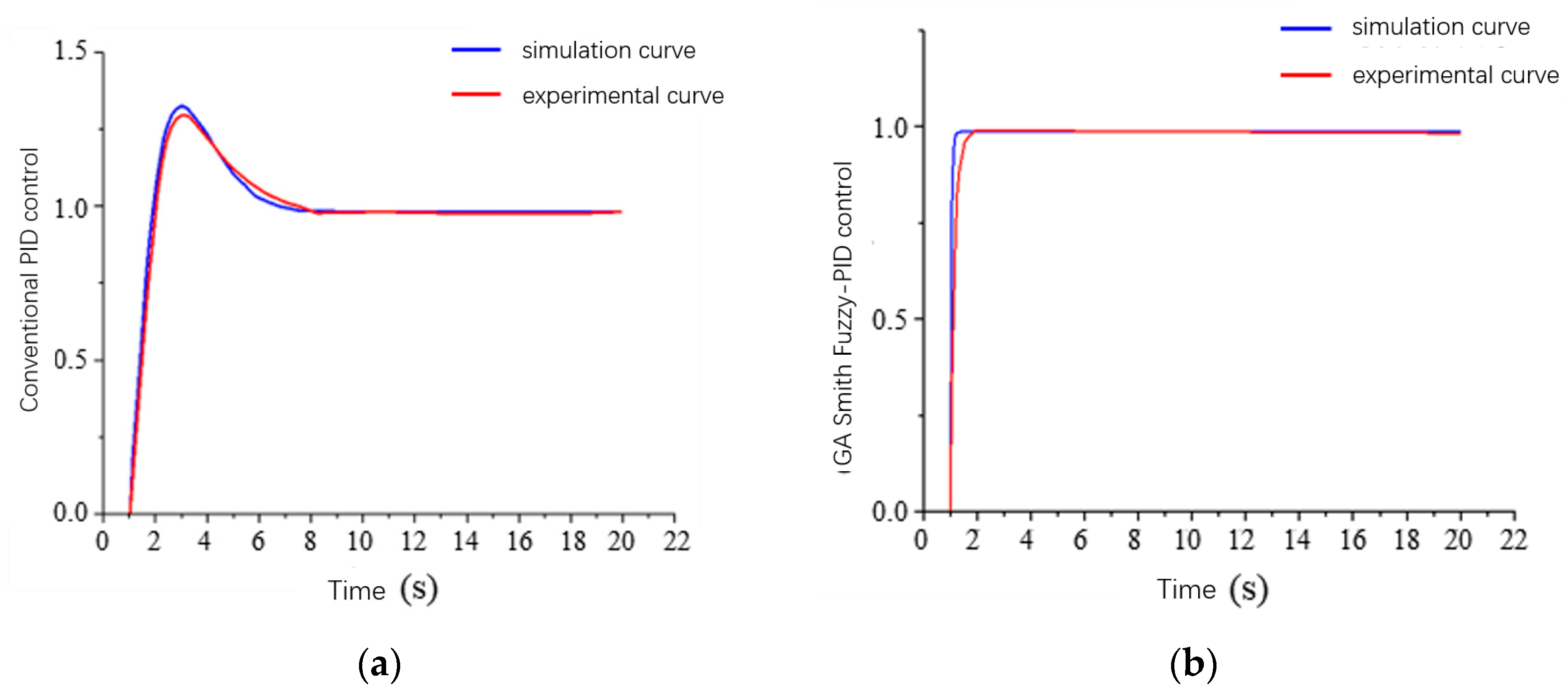
The control system uses the conventional PID control scheme and the Smith fuzzy PID control strategy optimized by the genetic algorithm to control the density of the slurry mixing process, and the trajectory module of the controller obtains an experimental output curve for each experiment, which represents the control signal of the controller to the valve. The experimental output curves of the conventional PID control and the Smith fuzzy PID control optimized by the genetic algorithm were compared with their respective theoretical simulation curves, and the results obtained are shown in Figure 16.
During the experiments, the current valve openness percentage could be read using the valve openness indicator dial, and the valve openness was recorded to achieve control of the valve by the conventional PID controller and the Smith fuzzy PID controller optimized by the genetic algorithm, as shown in Figure 17.
By analyzing the experimental output results of the slurry mixing control system, it can be seen that the experimental curve is not identical to the simulation curve; however, the difference was within the tolerance of error, which verifies the effectiveness of the designed controller.
It can be seen that the Smith fuzzy PID controller optimized by the genetic algorithm has a smaller overshoot, a faster response speed, and shorter regulation time than the conventional PID control in the face of the time-delay system of the slurry density control when comparing the results of the two experiments. Compared with the conventional PID control, the Smith fuzzy PID controller optimized by the genetic algorithm has obvious advantages and sufficient control performance. According to the experimental curve of valve openness, we were able to verify that the Smith fuzzy PID control optimized by the genetic algorithm will not produce large fluctuations and oscillations in the valve openness control process. Additionally, it has high stability and control accuracy and a short regulation time, which is more suitable for application in the control of slurry density time-delay systems.
As we simplified some of the procedures in the experiments and there were interference and instability factors noted during the experimental process, there may be some deviation between the experimental results and the simulation results; however, the results still verify the fact that the Smith fuzzy PID control optimized by the genetic algorithm has high stability and control accuracy and can achieve better control effects.
6. Summary
In this study, with reference to the time-delay problem of slurry density control, a mathematical model of the controlled object was established, the Smith fuzzy PID control scheme optimized by the genetic algorithm was innovatively proposed, and the simulation analysis and experimental verification of the control scheme were performed. We were able to confirm through simulation verification that the system with Smith fuzzy PID control optimized by the genetic algorithm demonstrated almost no occurrence of overshoot and that it has the best steady-state performance and the shortest rise time. We built a slurry mixing experimental platform, and the experimental results show that when the system set density was changed, the control time to reach the steady state of the Smith fuzzy PID control optimized by the genetic algorithm was shorter than that of the conventional PID control. Moreover, the valve openness records prove that the valve openness of the system with Smith fuzzy PID control optimized by the genetic algorithm changed more steadily to reach the steady state faster than that of the conventional PID control. Therefore, the experimental results show that the proposed optimization algorithm has an excellent control effect in actual application scenarios. The design of the mixing density control system described herein is based on theoretical and simulation calculations and experiments in a laboratory setting; however, because of the set conditions, it was not taken to an industrial site for testing. Actual engineering conditions are more complex, there are many interference factors present, and there also exists the subsequent opportunity to visit the actual site to carry out further testing.
Author Contributions
Conceptualization, J.C.; methodology, X.G. and H.Y.; software, G.H. and H.Y.; validation, C.H. and G.H.; formal analysis, X.G.; investigation, J.C.; resources, W.X.; data curation, G.H.; writing—original draft preparation, X.G. and G.H.; writing—review and editing, J.C.; visualization, C.H.; supervision, W.X. All authors have read and agreed to the published version of the manuscript.
Funding
This research received no external funding.
Institutional Review Board Statement
Not applicable.
Informed Consent Statement
Not applicable.
Data Availability Statement
The data presented in this study are available upon request from the corresponding author. The data are not publicly available due to privacy.
Acknowledgments
We sincerely acknowledge Lijiang Wang for his experimental facility support.
Conflicts of Interest
Author Xiang Gao was employed by the company Wanhua Chemical Group Co., Ltd. and author Huiwen Yang was employed by the company Cosco Shipping Heavy Industry Co., Ltd. The remaining authors declare that the research was conducted without any commercial or financial relationships that could be construed as a potential conflict of interest.
References
- Wen, Q. Research on the New Problems and Development Direction Faced by Domestic Cementing at Present. Mod. Bus. Tra. Ind. 2018, 39, 180–181. [Google Scholar]
- Blanchini, F.; Casagrande, D.; Miani, S. Stable LPV Realization of the Smith Predictor. Int. J. Syst. Sci. 2016, 47, 2393–2401. [Google Scholar] [CrossRef]
- Bai, J.B. Research on Adaptive Control of Test Room Air Conditioning System. Master’s Thesis, Southeast University, Nanjing, China, 2006. [Google Scholar]
- Mohamed, A.R.S.; Doaa, K.I.; Mostafa, B. Application of PSO Tuned Fuzzy Logic Controller for LFC of Two-area Power System with Redox Flow Battery and PV Solar Park. Ain. Shams. Eng. J. 2022, 13, 101710. [Google Scholar]
- Gao, J.; Zhang, J.; Feng, X. Main Steam Pressure Control Technology Based on Mismatch Compensated Smith-RBF Neural Network. J. Chongqing Univ. 2019, 42, 105–113. [Google Scholar]
- Ning, X.; Wang, Z.; Wang, C.; Wu, B. Adaptive Feedforward and Feedback Compensation Method for Real-time Hybrid Simulation Based on a Discrete Physical Testing System Model. J. Earthq. Eng. 2020, 26, 3841–3863. [Google Scholar] [CrossRef]
- Wang, J.S. Research on Precise Train Stopping Algorithm Based on Particle Swarm PID-Smith Controller. Sci. Tech. Inno. 2023, 15–19. [Google Scholar] [CrossRef]
- Liang, H.; Zou, J.; Zuo, K.; Khan, M.J. An Improved Genetic Algorithm Optimization Fuzzy Controller Applied to the Wellhead Back Pressure Control System. Mech. Syst. Signal PR 2020, 142, 106708. [Google Scholar] [CrossRef]
- Wang, Y.T.; Liu, J.; Li, J.C.; Chen, B.; Li, Q. Using the Smith PSO-Fuzzy PID Model to Control Electrical Conductivity of Nutrient Solution of Precision Fertilization. J. Irrig. Drain 2022, 41, 37–44. [Google Scholar]
- Moura, J.P.; Fonseca Neto, J.V.; Rego, P.H.M. A neuro-fuzzy model for online optimal tuning of pid controllers in industrial system applications to the mining sector. IEEE Trans. Fuzzy Syst. 2019, 28, 1864–1877. [Google Scholar] [CrossRef]
- Park, D.; Le, T.L.; Quynh, N.V.; Long, N.K.; Hong, S.K. Online tuning of pid controller using a multilayer fuzzy neural network design for quadcopter attitude tracking control. Front. Neurorobotics 2021, 14, 619350. [Google Scholar] [CrossRef] [PubMed]
- Han, H.G.; Wu, X.L.; Liu, Z.; Qiao, J.F. Design of self-organizing intelligent controller using fuzzy neural network. IEEE Trans. Fuzzy Syst. 2018, 26, 3037–3111. [Google Scholar] [CrossRef]
- Liu, J.W.; Tao, X.; Ma, X.Y.; Feng, K.G.; Chen, J.M. Fuzzy controllers with neural network predictor for second-order linear systems with time delay. IEEE Access 2020, 8, 206049–206062. [Google Scholar] [CrossRef]
- Fang, Y.K.; Cheng, C.Y.; Dong, Z.; Min, H.G.; Zhao, X.M. A fault diagnosis framework for autonomous vehicles based on hybrid data analysis methods combined with fuzzy PID control. In Proceedings of the International Conference on Unmanned Systems, Harbin, China, 27–28 November 2020. [Google Scholar]
- Lei, Y.; Wu, Y.Q.; Yuan, Y.Q.; Chen, C. Intelligent neural network controller optimization and simulation using GA. In Proceedings of the International Conference on Intelligent Transportation, Big Data & Smart City (ICITBS), Changsha, China, 12–13 January 2019. [Google Scholar]
- Feng, Y.; Wu, M.; Chen, X.; Chen, L.; Du, S. A fuzzy pid controller with nonlinear compensation term for mold level of continuous casting process. Inf. Sci. 2020, 539, 487–503. [Google Scholar] [CrossRef]
- Zhang, R.M.; Zeng, D.Q.; Ju, H.P.; Lam, H.K.; Xie, X.P. Fuzzy sampled-data control for synchronization of t-s fuzzy reaction-diffusion neural networks with additive time-varying delays. IEEE Trans. Cybern. 2021, 51, 2384–2397. [Google Scholar] [CrossRef] [PubMed]
- Shi, Q.; Lam, H.K.; Xuan, C.B.; Chen, M. Adaptive neuro-fuzzy pid controller based on twin delayed deep deterministic policy gradient algorithm. Neurocomputing 2020, 402, 183–194. [Google Scholar] [CrossRef]
- Fathollahi, A.; Andresen, B. Multi-Machine Power System Transient Stability Enhancement Utilizing a Fractional Order-Based Nonlinear Stabilizer. Fractal Fract. 2023, 7, 808. [Google Scholar] [CrossRef]
- Fathollahi, A.; Gheisarnejad, M. Robust Artificial intelligence Controller for Stabilization of Full-Bridge Converters Feeding Constant Power Loads. IEEE Trans. Circuits Syst. II Express Briefs 2023, 70, 3504–3508. [Google Scholar] [CrossRef]
- Mpalaskas, A.C.; Matikas, T.E.; Aggelis, D.G. Acoustic monitoring for the evaluation of concrete structures and materials. In Acoustic Emission and Related Non-Destructive Evaluation Techniques in the Fracture Mechanics of Concrete; Woodhead Publishing: Sawston, UK, 2015; pp. 269–286. [Google Scholar]
- Panagiotis, G.A.; Paulo, B.L.; Panayiotis, C.R. Revealing the nature of metakaolin-based concrete materials using artificial intelligence techniques. Constr. Build. Mater. 2022, 322, 126500. [Google Scholar]
- Liu, Y.H. Research on Speed Tracking Control of Permanent Magnet Maglev Train Based on Predictive Fuzzy PID Control Algorithm. Master’s Thesis, Jiangxi University of Science and Technology, Nanchang, China, 2022; pp. 5–16. [Google Scholar]
- Hong, Z.Q.; Xu, W.B.; Lv, C.; Ouyang, Q.; Wang, Z.S. Deep Reinforcement Learning-PI Air Rudder Servo System Control Strategy Based on Genetic Algorithm Optimization. J. Mech. Elec. Eng. 2023, 40, 1071–1078. [Google Scholar]
- Yu, Z.; Fu, Y.G.; Zhang, J. Simulation of Stellar Spectrum Controlled by Fuzzy PID. Opt. Precision Eng. 2023, 31, 1619–1630. [Google Scholar]
Figure 1.
Control schematic of the automatic slurry mixing system.

Figure 2.
Cementing mixing system density control process.

Figure 3.
Fuzzy PID control schematic.

Figure 4.
Input membership function. (a) e membership function plots. (b) ec membership function plots.
Figure 4.
Input membership function. (a) e membership function plots. (b) ec membership function plots.

Figure 5.
Output membership function. (a) Kp membership function plots. (b) Ki membership function plots. (c) Kd membership function plots.
Figure 5.
Output membership function. (a) Kp membership function plots. (b) Ki membership function plots. (c) Kd membership function plots.

Figure 6.
Controller simulation model.

Figure 7.
Internal structure diagram of the fuzzy controller.

Figure 8.
MATLAB simulation diagram of three control algorithms.

Figure 9.
Schematic of Smith fuzzy PID control optimized by the genetic algorithm.

Figure 10.
The process of fuzzy control optimized by the genetic algorithm.

Figure 11.
Simulation structure of the Smith fuzzy PID controller optimized by the genetic algorithm.
Figure 11.
Simulation structure of the Smith fuzzy PID controller optimized by the genetic algorithm.

Figure 12.
Genetic algorithm adaptation curve.

Figure 13.
MATLAB simulation diagram of the four control algorithms.

Figure 14.
Principle diagram of the slurry mixing experiment. 1—PLC; 2—computer; 3—water flowmeter; 4—high-energy mixer; 5—cement pump; 6—water pump; 7—proportional solenoid valve; 9—densitometer; 10—slurry mixing tank; 11—recirculating pump; 12—boost pump; 13—triplex plunger pump.
Figure 14.
Principle diagram of the slurry mixing experiment. 1—PLC; 2—computer; 3—water flowmeter; 4—high-energy mixer; 5—cement pump; 6—water pump; 7—proportional solenoid valve; 9—densitometer; 10—slurry mixing tank; 11—recirculating pump; 12—boost pump; 13—triplex plunger pump.

Figure 15.
Slurry density control experimental platform. 1—PLC; 2—side-mounted densitometer; 3—agitator; 4—water flowmeter.
Figure 15.
Slurry density control experimental platform. 1—PLC; 2—side-mounted densitometer; 3—agitator; 4—water flowmeter.

Figure 16.
Control algorithm output curves. (a) PID control output curve. (b) GA Smith fuzzy PID control output curve.
Figure 16.
Control algorithm output curves. (a) PID control output curve. (b) GA Smith fuzzy PID control output curve.

Figure 17.
Experimental curve of valve openness.


Table 1.
Input and output domain of the discourse range.
| Variable | Range |
|---|---|
| e | [−3, 3] |
| ec | [−3, 3] |
| Kp | [−0.3, 0.3] |
| Ki | [−0.06, 0.06] |
| Kd | [−0.3, 0.3] |
Table 2.
ΔKp fuzzy inference table.
| e | ec | ||||||
|---|---|---|---|---|---|---|---|
| NB | NM | NS | ZO | PS | PM | PB | |
| NB | PB/NB/PS | PB/NB/NS | PM/NM/NB | PM/NM/NB | PS/NS/NB | ZO/ZO/NM | ZO/ZO/NM |
| NM | PB/NB/PS | PB/NB/NS | PM/NM/NM | PS/NS/NM | PS/NS/NM | ZO/ZO/NS | NS/ZO/ZO |
| NS | PM/NB/ZO | PM/NM/NS | PM/NS/NM | PS/NS/NM | ZO/ZO/NS | NS/PS/NS | NS/PS/ZO |
| ZO | PM/NM/ZO | PM/NM/NS | PS/NS/NM | ZO/ZO/NS | NS/PS/NS | NM/PM/NS | NM/PM/ZO |
| PS | PS/NM/ZO | PS/NS/ZO | ZO/ZO/ZO | NS/PS/ZO | NS/PS/ZO | NM/PM/ZO | NM/PB/ZO |
| PM | PS/ZO/PB | ZO/ZO/NS | NS/PS/PS | NM/PS/PS | NM/PM/PS | NM/PB/PS | NB/PB/PB |
| PB | ZO/ZO/PB | ZO/ZO/PM | NM/PS/PM | NM/PM/PM | NM/PM/PS | NB/PB/PS | NB/PB/PB |
Table 3.
Controller system performance indexes.
| Operating Parameter | Rise Time (s) | Peak Value | Overshoot | Stabilization Time (s) |
|---|---|---|---|---|
| Conventional PID Control | 1.875 | 1.36 | 35.6% | 6.985 |
| Smith Predictive Control | 1.071 | 1.02 | 2. 1% | 1.165 |
| Smith Fuzzy PID Control | 0.702 | 1.01 | 1. 3% | 0.732 |
| GA Smith Fuzzy PID Control | 0.450 | 1.01 | 0. 9% | 0.464 |
Disclaimer/Publisher’s Note: The statements, opinions and data contained in all publications are solely those of the individual author(s) and contributor(s) and not of MDPI and/or the editor(s). MDPI and/or the editor(s) disclaim responsibility for any injury to people or property resulting from any ideas, methods, instructions or products referred to in the content. |
© 2024 by the authors. Licensee MDPI, Basel, Switzerland. This article is an open access article distributed under the terms and conditions of the Creative Commons Attribution (CC BY) license (https://creativecommons.org/licenses/by/4.0/).
Share and Cite
MDPI and ACS Style
Gao, X.; Hou, G.; Yang, H.; Hu, C.; Cui, J.; Xiao, W. Research on the Autonomous Control Technology Used in the Slurry Mixing System of Cementing Units. Appl. Sci. 2024, 14, 3568. https://doi.org/10.3390/app14093568
AMA Style
Gao X, Hou G, Yang H, Hu C, Cui J, Xiao W. Research on the Autonomous Control Technology Used in the Slurry Mixing System of Cementing Units. Applied Sciences. 2024; 14(9):3568. https://doi.org/10.3390/app14093568
Chicago/Turabian StyleGao, Xiang, Guojian Hou, Huiwen Yang, Changmiao Hu, Junguo Cui, and Wensheng Xiao. 2024. "Research on the Autonomous Control Technology Used in the Slurry Mixing System of Cementing Units" Applied Sciences 14, no. 9: 3568. https://doi.org/10.3390/app14093568
Note that from the first issue of 2016, this journal uses article numbers instead of page numbers. See further details here.