
Iterative Learning with Adaptive Sliding Mode Control for Trajectory Tracking of Fast Tool Servo Systems
by
 , ,
, ,
Xiuying Xu
1, 
Pengbo Liu
1,2,* ,
,
Shuaishuai Lu
1,2,
Fei Wang
1,2,
Jingfang Yang
1,2 and
Guangchun Xiao
1,2 1
School of Mechanical Engineering, Qilu University of Technology (Shandong Academy of Sciences), Jinan 250353, China
2
Shandong Institute of Mechanical Design and Research, Jinan 250031, China
*
Author to whom correspondence should be addressed.
Appl. Sci. 2024, 14(9), 3586; https://doi.org/10.3390/app14093586
Submission received: 12 March 2024
/
Revised: 8 April 2024
/
Accepted: 22 April 2024
/
Published: 24 April 2024
(This article belongs to the Section Mechanical Engineering)
Abstract
:To address the tracking control problem of the periodic motion fast tool servo system (FTS), we propose a control method that combines adaptive sliding mode control with closed-loop iterative learning control. Adaptive sliding mode control enhances the system’s robustness to external non-repetitive disturbances, and exponential gain iterative learning control compensates for the influence of periodic disturbances such as cutting force. The experimental results show that the proposed iterative learning controller based on adaptive sliding mode control can effectively eliminate the influence of various interference factors, achieve accurate tracking of the FTS system’s motion trajectory within a limited number of iterations, and ensure the stability of the system, which has the advantages of a fast convergence speed, high tracking accuracy, and strong robustness.
1. Introduction
The piezoelectric-driven fast tool servo (FTS) system [1,2,3] is a set of micro-feed servo systems that are commonly used to process and manufacture nanoscale free-form surfaces. It utilizes the inverse piezoelectric effect of piezoelectric ceramic materials [4] to generate a drive force that moves the tool. This system has the advantages of a high-frequency response, high stiffness, and high positioning accuracy [5,6]. During the FTS machining process, due to the periodicity of the spindle rotation, the FTS system needs to accurately track specific repetitive signals. Disturbance conditions such as changes in the processing load, changes in the external environment, and time delays in data processing pose severe challenges to the motion accuracy of the FTS system, and the motion accuracy determines the processing quality of the FTS system [7,8]. Therefore, in order to suppress various interferences that affect the tool movement, the fast tool servo system needs to be precisely controlled so that the tool path meets the processing requirements of the workpiece surface accuracy and surface roughness [9].
The motion accuracy of the FTS system is mainly determined by the control algorithm. The commonly used control methods are repetitive control [10,11], PID control [12], sliding mode control [13], adaptive control [14], etc. Due to its insensitivity to disturbance and good robustness, sliding mode control (SMC) [15,16] is often applied to deal with system uncertainties and external disturbances, and it has been widely used in the controller design of the FTS system. Zhang et al. [17] designed a combined approximation law consisting of an exponential approximation law and a variable rate approximation law, and established a new variable structure sliding mode controller, which effectively reduced the steady-state error of the FTS system. Chang et al. [18] proposed a non-singular terminal sliding mode controller (NTSMC) for the non-axisymmetric aspheric surface machining of the piezoelectric-driven FTS system. Through simulation and experimental examinations, the NTSMC capable of improving tracking error was verified.
Due to possible variations in the workpiece shape and material properties during the machining process of the fast tool servo system, the adjustment of parameters for the sliding mode controller is limited. Therefore, adaptive control is needed to continuously adjust the control parameters to accommodate changes in the system. The combination of adaptive control and SMC can continuously extract information about the control during the operation of the FTS system, adjust the control parameters through adaptive algorithms, so that the system automatically works in the optimal operating state or close to the optimal operating state, and is able to compensate for non-linear hysteresis, model uncertainty, and non-periodic disturbances caused by other external disturbances [19]. Wu-Le Zhu et al. [20] developed an adaptive terminal sliding mode with online self-adjusting system gain and arrival time-related parameters in order to adapt to system nonlinearity, cutting force disturbance, and fast and accurate tracking of specified tool trajectories required for free-form diamond machining.
In FTS systems, periodic disturbance is often caused by cutting force changes, workpiece structural resonance, and other factors, which brings instability and volatility to the machining process. Liu et al. [21] proposed a robust iterative learning control strategy based on adaptive sliding mode control for the purpose of torque ripple in the permanent magnet synchronous motor speed control system and the periodic disturbance of the system. Iterative learning control (ILC) [22,23] is one of the important methods in the field of learning control, which can gradually suppress these periodic disturbances and make the processing process more stable and controllable. Armin et al. [24] combined the proportional-derivative type iterative learning controller (PD-ILC) and the adaptive sliding mode controller (ASMC) and applied it to a two-degree-of-freedom (2-DOF) rotary pendulum, which improved the system’s convergence speed and tracking performance. Based on the above research and considering the particularity of FTS system processing, we introduced exponential convergence iterative learning control based on adaptive sliding mode control to compensate for the impact of periodic disturbances such as cutting force on the FTS system [25].
In this manuscript, we developed the iterative learning with adaptive sliding mode control for fast tool servo systems to solve the impact of disturbance factors such as model uncertainty, cutting force, mechanical vibration, and temperature changes on the tracking accuracy of the fast tool servo system during the machining process of the fast tool servo system. In particular, ASMC overcomes the chattering problem through adaptive switching gain based on tracking error, adjusts its switching gain online, and resists uncertainty in model parameters and sudden external disturbance. ILC solves the impact of periodic disturbance such as spindle vibration and cutting force during the periodic machining process of the fast tool servo system, and improves the convergence speed and tracking accuracy of the fast tool servo system. According to the real-time experimental results on the FTS prototype, the developed control method demonstrated has a good suppression effect on disturbance and it realizes the optimization of the tracking motion of the fast tool servo system in a complex processing environment. The main contribution of the paper can be succinctly summarized as follows:
- (1)
- An improved adaptive sliding mode control is proposed to adjust the control gain online improved system anti-disturbance and robustness.
- (2)
- The exponential convergence iterative learning control is employed to inhibit the periodic disturbance. Combined with the adaptive sliding mode control, the optimization of the tracking motion of the fast tool servo system in complex processing environments is achieved.
The remainder of this article is organized as follows. Section 2 introduces the mathematical modeling of the piezoelectric-driven FTS system. Section 3 proposes adaptive SMC for non-periodic disturbances such as uncertainty in the FTS system. Section 4 designs a PD-type ILC to compensate for the periodic disturbance of the FTS system. Section 5 presents real-time experiments conducted to verify the performance of the proposed control structure. Section 6 gives some conclusions.
2. Piezoelectric-Driven FTS System
The working principle of the FTS system is shown in Figure 1a. The workpiece moves with the spindle, and the spindle is located on the X-axis. The FTS system is carried by the Z-axis. The X-axis and Z-axis work together to perform a high-speed reciprocating motion to achieve the fast and fine movement of the diamond tool.
2.1. FTS System Description
The key requirements for FTS system design are to achieve a large stroke, high precision, and high stiffness to maintain high resistance and sensitivity to external cutting forces [8]. In view of the application requirements, we proposed a piezoelectric-driven FTS system based on a three-dimensional bridge amplification mechanism [26], as shown in Figure 1b. From a structural point of view, it adopts a three-dimensional bridge amplification structure, which is composed of a single-arm bridge type and a double-arm bridge type connected in series. The two-stage amplification mechanism is combined by a threaded connection. The piezoelectric ceramic is installed between the two input ends of the main amplification mechanism. Its position is fixed and pre-tightened by bolts, and has input and output guide constraints, thereby improving the stiffness and accuracy of the system.
2.2. Dynamic Modeling of FTS System
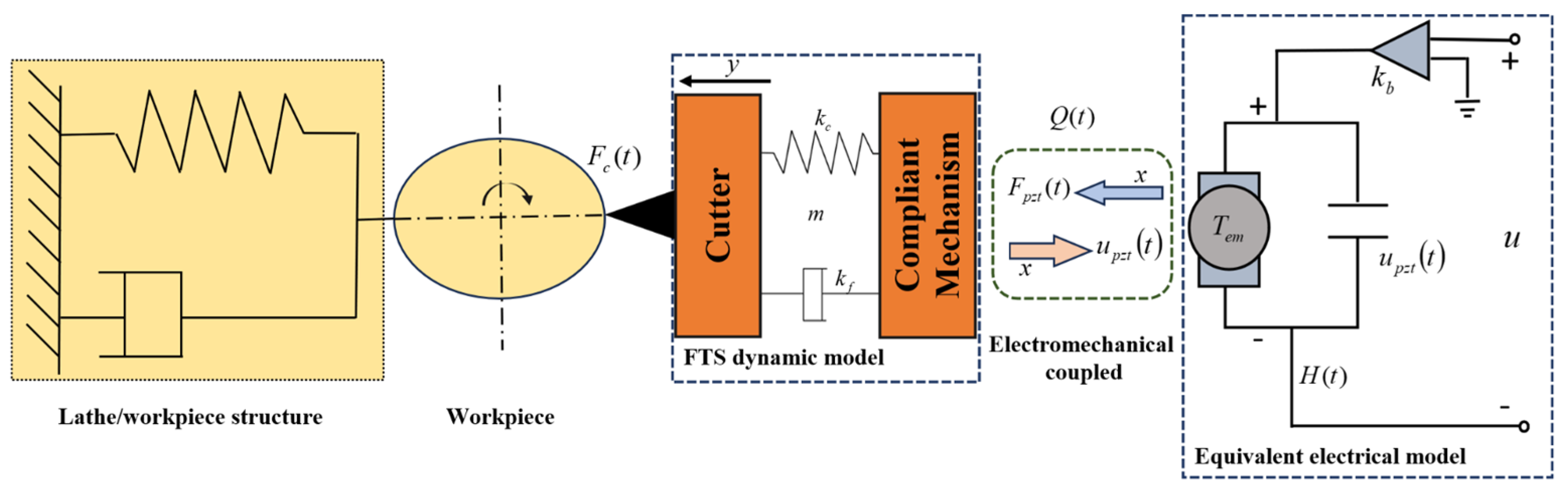
The piezoelectric-driven FTS system is a typical electromechanical coupled system. From an electrical perspective, the piezoelectric ceramic actuator is regarded as a capacitor, and the voltage amplifier is viewed as a constant amplifier. From mechanical analysis, the flexible actuator and the tool holder are considered as a whole, taking into account the elastic contact issue of the flexible actuator, and it is regarded as a mass-spring-damping system. Therefore, the dynamic model of the FTS system is shown in Figure 2.
In Figure 2, represents the quality coefficient of the flexible actuator. represents the damping coefficient of the flexible actuator, and represents the spring coefficient of the flexible actuator. represents the gain of the piezoelectric amplifier, represents the system control voltage, represents the tool output displacement of the FTS system, and represents the force generated by the deformation of the piezoelectric ceramic driver. represents the deformation amount of the piezoelectric ceramic actuator, and represents the electromechanical conversion efficiency of the piezoelectric ceramics. , , and represent the system’s nonlinear hysteresis, cutting force disturbance, model uncertainty, and other external disturbance term.
Based on Kirchhoff’s voltage law, the voltage applied to the piezoelectric ceramic is
According to Newton’s law [20]
To facilitate the controller design, the actual system can be further represented by the state variables of and as follows
where , , , . The related problem we need to solve is how to achieve an accurate tracking of the desired motion trajectory in the presence of equivalent disturbances .
3. Adaptive Sliding Mode Control (ASMC) Design
Considering the system uncertainty and parameter changes caused by dynamic machining loads, as well as the various disturbances present in the machining process, the motion control of the fast tool servo system, which determines the machining quality, is full of challenges. We adopt the SMC for the FTS systems, due to sliding mode control having good robustness to external disturbances. Combining the characteristics of SMC and adaptive control, the transient response and robustness of the FTS system processing process are improved. Estimating the parameters of the system online and then using the estimated parameters for calculation during the control process has the characteristic of quickly converging the tracking error to the equilibrium point.
3.1. SMC Design
The system position tracking error is defined as
For the FTS system that performs a periodic motion in the iterative domain [0, T], the input trajectory is recorded as the expected position function, and is the actual position trajectory.
Based on the position tracking error, the PID sliding mode surface [27] is defined as
where the constant is strictly positive. is the integral variable. The integral term is used to improve the transient response and reduce the steady-state error in the sliding surface compared with the traditional sliding mode surface. When the system state approaches the sliding mode surface, can ensure good dynamic performance. In addition, can improve the stability of the control method.
The control law is selected as follows
Let Equation (4) be zero and ignore the disturbance, the equivalent control is derived as follows [28].
Switching control input for tracking system uncertainty is chosen as
where , . is the upper bound of disturbance, thus ensuring the controller’s suppression of system disturbances. and are the adjustable switching gains of the sliding mode controller, which are used to change the error convergence speed of the approaching phase and sliding phase of the SMC. It can make the initial point far away from the sliding mode surface converge quickly in the process of approaching the sliding mode surface, and the speed is small when approaching the sliding mode surface, which not only ensures the convergence speed of the algorithm, but also weakens the control torque buffeting to ensure system control performance.
3.2. ASMC Design
In the actual processing of the FTS system, factors such as workpiece shape, material properties, and environmental changes often change, which brings challenges to the control system. Traditional control methods often struggle to cope with these changes because they often rely on predetermined models and parameters. Adaptive control has strong adaptability and can adjust control parameters in real time according to system dynamic characteristics and changes in the external environment, thereby maintaining the stability and efficiency of system performance. Therefore, we updated it based on the adaptive control proposed in the reference [29]. The adaptive law is as follows
This article uses adaptive parameter estimation instead of the switching gain . This adaptive switching gain is designed to resist model parameter uncertainty and sudden external disturbances. is a positive constant that exponentially determines the convergence rate of the adaptive switching gain.
Rewrite the control law (7) as
By examining the adaptive rule (10), it can be seen that the adaptive effect depends on the control parameter . Generally speaking, the larger the parameter , the faster the adaptation process. In practical applications, due to the presence of sensor noise, an endless adaptive process may occur, resulting in the value of gain being too large. In order to avoid this problem, the following improvements are made to the adaptive rules in actual implementation.
where is the assigned threshold value of the tracking error bound. When the tracking error is suppressed within the bound of , the control parameters will maintain constant thereafter without adaption and the error will be kept by the bound . Otherwise, the control gains will be updated again. Thus, the position tracking error bound can be predefined, which is desirable for practical application.
The defects of SMC itself and the delay and lag of control information in actual engineering applications cause chattering in the sliding mode of the system. For continuous systems, the quasi-sliding mode method is usually used to suppress the occurrence of this phenomenon, that is, by setting a certain Δ neighborhood of the ideal sliding mode and limiting the motion trajectory of the system to this neighborhood. The following quasi-SMC method is generally used: the sign function in the ideal sliding mode is replaced by a saturation function.
Among them, Δ is called the boundary layer. Outside the boundary layer, the saturation function uses linearized feedback control, while inside the boundary layer, switching control is used.
3.3. Proof of Stability
Based on the model (4), the time derivative of in Equation (6) is derived as follows
In order to verify the stability of the above control scheme, consider the Lyapunov candidate function as follows
where . Then the time derivative of is
Among them, when , is expressed as
With the assumption of the external disturbance, , is then expressed as
Therefore
It is proved that the time derivative of the Lyapunov candidate function used is negative definite, which ensures the asymptotic stability of the control system and the existence of the sliding mode.
4. Iterative Learning Control with Adaptive Sliding Mode Control (ILC-ASMC)
Combining SMC with ILC can not only improve the problem of the poor control performance of ILC for FTS systems with initial state errors and slow convergence speed in the iterative domain, but also improve trajectory tracking accuracy and compensate for the disturbance caused by impact.
4.1. PD-Type Iterative Learning Controller Design
ILC is suitable for controlled objects with periodic motion and does not rely on accurate mathematical models. It has a significant control effect on systems with strong coupling, model uncertainty, and high-precision tracking requirements. Reference [30] uses P-type iterative learning to deal with repeated disturbance during the operation of CNC machine tools. For this purpose, this paper proposes an improved exponential convergence PD-type iterative learning control. It is suitable for FTS systems and has faster response capabilities and real-time adjustment mechanisms. The improved iterative learning control is combined with the ASMC method to obtain a composite control that combines the advantages of the two control methods, gradually eliminating the non-periodic and periodic disturbances of the system, and obtaining better control effects. The system control structure is shown in Figure 3.
When using ILC, the state equation at the k-th iteration can be written as follows according to Equation (4).
where , k is the number of iterations , is the system state vector, is the system control vector, is the system output vector, is the total disturbance of the system, , , and are the matrices of corresponding dimensions.
Define the error of the k-th iteration trajectory tracking as
where represents the expected trajectory, and represents the output of the k-th iteration of the system.
Control signal consists of two parts during any iteration: SMC and ILC .
Generally, the iterative learning controller is designed as
where is the learning gain, and is the control input filter. k is the iteration number and denotes the k-th control input. Different types of ILC controllers can be obtained by modifying the matrices and . Taking Q as the identity matrix, we get
where the current period control input is a function of the error and control input of the previous period. Take the closed-loop PD-type ILC law
where parameters and are the learning gains. PD-type ILCs are very similar to traditional PD controllers, but instead of handling system response, PD-type ILCs handle errors while maintaining a linear effect on the past input signal.
Most learning laws prove that the sufficient condition for learning convergence is the number of iterations . It is necessary to consider making the iterative learning process converge to the expected value faster. Therefore, the ILC based on exponential gain is proposed by adding to the gain of the control law. The correction coefficient speeds up the convergence speed of ILC.
Take the closed-loop PD-type ILC law based on exponential gain
where is the gain correction coefficient.
Substituting Equations (11) and (26) into Equation (23), the hybrid control law is calculated as
The sliding mode feedback controller in the SMC law design part can enable the FTS system to reach the target trajectory and suppress the influence of non-periodic disturbance factors. Subsequently, an ILC is triggered to further suppress the effects of periodic disturbances. By increasing the number of iterations and combining the two control strategies, the system output can accurately and quickly track the desired output. Therefore, for nonlinear uncertain systems subject to external disturbance, the control input signal obtained by combining the output of the second-order sliding mode and the output based on the exponential gain ILC converges the error to zero through iteration.
4.2. Convergence Analysis
In this section, in order to update the control law of SMC, the convergence analysis is studied. The control effect in Equation (22) is achieved using the control in Equations (7) and (26). Substitute the combined control Equation (22) into Equation (14).
Among them, represents the Laplacian operator. At the same time, is a bounded disturbance term. Assuming that all signals are available in the frequency domain, Equation (28) in the k + 1-th iteration is as follows
By substituting the exponential convergence iterative learning control update law in Equation (26) into Equation (28), we get the following equation
Equation (28) can be organized as
By substituting Equation (31) into Equation (30), we obtain the following equation
The initial conditions for each iteration are , when , . Therefore, . Equation (32) is simplified to
Regard the sliding surface as
The tracking error can be represented as
where and are defined as
It can be deduced by a recursive algorithm
In a nonlinear uncertain iterative system, when , and the disturbance remains unchanged throughout iterations, from Equations (35) and (37), it can be seen that the time-varying disturbance becomes zero. Where acts as a low-pass filter, significantly reducing the high-frequency chattering generated by sliding mode control. When the coefficient . , , , satisfy . The proposed exponential convergence iterative learning control law based on adaptive sliding mode control can guarantee that after k-th iterations, the output error asymptotically converges to a neighborhood close to zero, satisfying the following equation
5. Experimental Verification
5.1. Experimental System
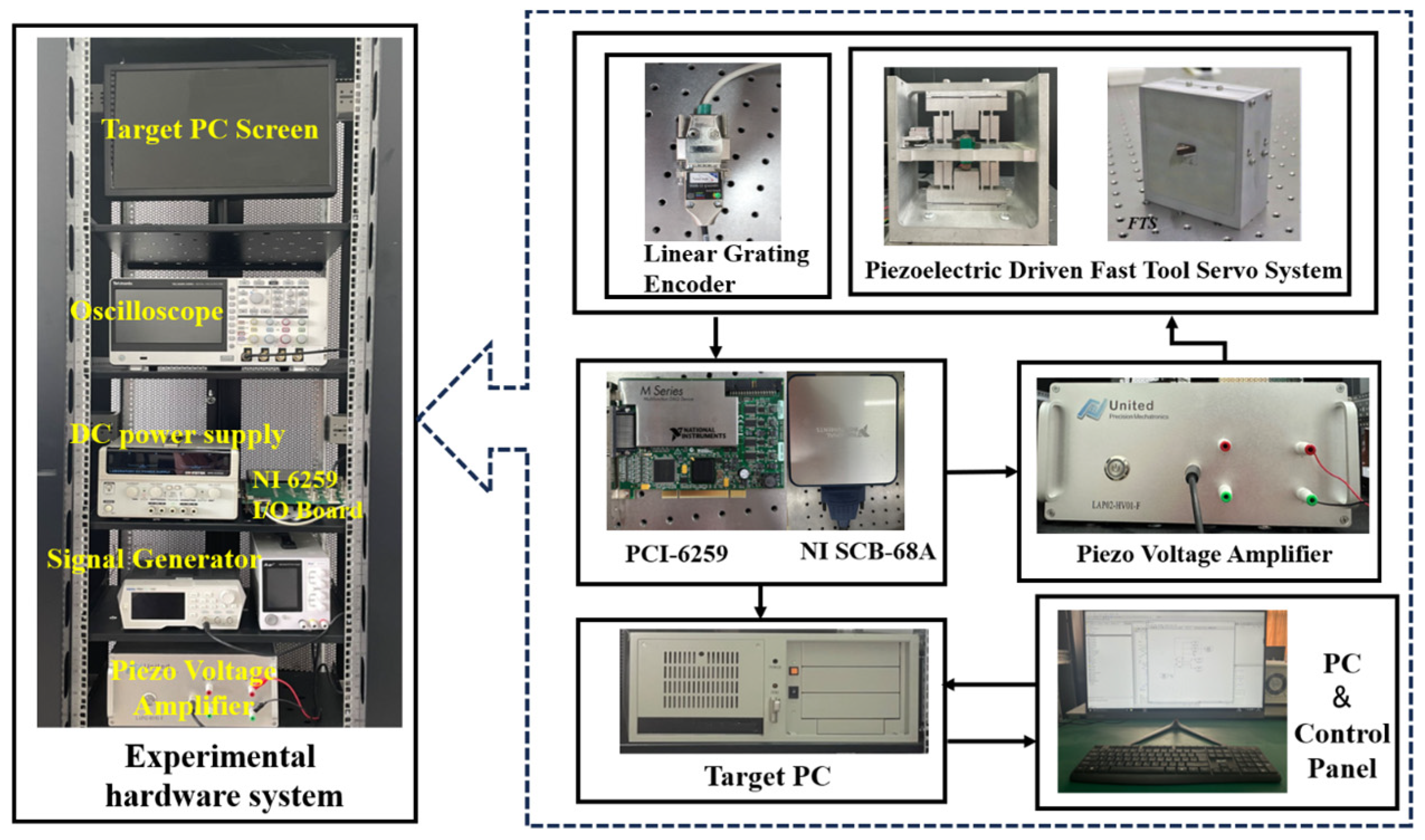
In order to verify the effectiveness and feasibility of the proposed control structure, this section uses an experimental design to test the theoretical design. The proposed control structure was tested on a piezoelectric-driven FTS prototype. The experimental platform design is shown in Figure 4. The experimental system uses a piezoelectric amplifier with a fixed gain ratio of 20 to amplify the input signal driving the piezoelectric ceramics. A high-bandwidth encoder with a measurement resolution of 1.2 nm is used to measure the displacement of the end effector in real time. The data acquisition system (NI PCI-6259) is equipped with a 16-bit digital-to-analog converter and a 16-bit analog-to-digital converter to provide voltage to the amplifier and collect data from the encoder. The piezoelectric-driven FTS system runs at a sampling frequency of 10 kHz in a Simulink/Matlab R2021a environment.
5.2. Parameter Identification
The PC computer inputs the model identification system program, and the Target PC computer generates a voltage signal that excites the piezoelectric ceramic driver, and collects the displacement information of the tool holder movement of the FTS system in real time.
Using a sine wave with an amplitude of 10 mV and a frequency range from 0.1 Hz to 1000 Hz as the input signal, the corresponding open-loop system input signal and output signal are obtained. The amplitude-frequency and phase-frequency curves of the system are calculated through the input signal and output signal [31].
The FTS system we designed is based on a compliant mechanism. Compliant mechanisms inherently possess infinite dimensions characteristics. Thus, from the perspective of control system design, it is simplified into a second-order system. The significant discrepancy between the red and blue lines at high frequencies in Figure 5 is attributed to the presence of an unmodeled modal (unmodeled dynamic characteristics) at high frequencies. These modalities are treated as disturbances and compensated for as part of the total disturbance during the controller design.
Therefore, based on the experimental results, a second-order transfer function is used to approximate the dynamic response of the FTS system. The sampling time of the entire system is T = 0.0001 s. MATLAB data are used to simulate the combined command, and FTS plant recognition is
For controller design, the parameters of the electromechanical modeling model defined by Equation (2) can be determined, from which we obtain the following model parameters: . Since the load conditions are not considered in the system identification, the cutting forces in actual machining will affect the performance of the PZT driver. Due to the robustness of the SMC controller, fluctuations in cutting force are also considered as an external disturbance and compensated in the controller.
The parameters of the proposed controller are initially selected through MATLAB/Simulink simulation and then adjusted through experimental methods. Specifically, the value of the parameter related to the selected sliding surface in Equation (6) is related to the rate at which the error converges to zero when the system reaches the sliding surface, so it is selected as follows: . Parameter in Equation (9) that affects the arrival speed of the sliding phase is positively correlated with the amplitude of the control signal.
5.3. Experimental Results
In order to verify the effectiveness of the proposed control strategy, after determining the parameters of the control system, the sinusoidal signal is used as the desired displacement command to conduct a tracking control experiment. In the sinusoidal signal tracking experiment, four controllers, PID control, traditional sliding mode control (SMC), adaptive sliding mode control (ASMC), and adaptive sliding mode control with PD-type iterative learning control (ILC-ASMC), were selected for comparison. The tracking experiment uses the reference command of a 40 Hz sinusoidal trajectory with a maximum peak value of 20 µm to test the tracking performance under three control schemes.
In this experiment, the iteration time interval is set to [0, 0.5] s, and the number of iterations is set to a fixed value of 10 times.
5.3.1. PID Control Comparison Experiment
Figure 6 shows the experimental results of PID and ILC-ASMC controllers. The ILC -ASMC control effect is significantly better than the PID control effect. As shown in Table 1, the control performance is improved by 89.46% and 89.78%, respectively, which is not only reflected in the tracking accuracy of the reference signal, but also in the convergence speed. Therefore, it can be shown that the proposed controller has strong robustness to system disturbance and greatly improves the operating accuracy of FTS.
5.3.2. SMC Comparison Experiments
Comparing ILC-ASMC with SMC and ASMC, the experimental results are shown in Figure 7. The reference tracking results show that after adding the adaptive law, the control performance of ASMC is greatly improved compared with the traditional SMC, and the tracking accuracy is increased by 41.49% and 37.47%, respectively. The better tracking effect of ILC-ASMC than ASMC is due to the increased learning gain of iterative learning. As shown in Table 1, the tracking effect of ILC-ASMC is 83.40% and 75.44% higher than that of ASMC, respectively. From this point of view, SMC effectively handles system disturbances, and periodic disturbances during repeated movements are suppressed through ILC. The experimental results verify the effectiveness of the proposed control scheme in terms of tracking and anti-disturbance performance.
5.3.3. Comparison of Errors at Different Iteration Times
Figure 8 shows the trajectory tracking error plots for iterations 2, 4, 6, 8, and 10. The ILC-ASMC can significantly improve the tracking accuracy in just a few iterations in the case of a sinusoidal signal reference. The absolute value of the maximum position tracking error tends to 0, achieving accurate tracking. The proposed ILC-ASMC algorithm can converge the initial state error to close to zero in a short time, ensuring that the FTS system can track the desired trajectory in a short time. The designed ILC is sufficiently robust to periodic disturbances. The controller can not only achieve a fast dynamic response while tracking the design trajectory, but also improve the anti-disturbance performance of the FTS system.
5.3.4. Robustness Testing
In practical applications, the FTS system is greatly affected by the load during the processing process, and changes in the load often cause changes in the tracking error of the system. Therefore, in order to simulate the impact of load during the machining process, we applied a constant force of 1N on the tool end of the FTS system to simulate the impact of the load during the cutting process on the stability of the proposed control structure.
The experimental results are shown in Figure 9 and elaborated upon in Table 2, the introduction of load demonstrates a discernible augmentation in the iterative tracking performance of ILC-ASMC in contrast to the ASMC. The tracking accuracy is improved by 73.46% and 64.35%, respectively. Therefore, the proposed control structure has better robustness.
5.3.5. Disturbance Rejecting Testing
In order to verify the anti-disturbance performance of the proposed controller, a periodic multi-frequency disturbance, as shown in Figure 10, was set up during the experiment to simulate the impact of a periodic disturbance, such as spindle vibration and cutting force, on the machining process of the piezoelectric-driven FTS system. The amplitude of the set disturbance signal is much larger than the actual disturbance to the system during the machining process, which is enough to represent the actual disturbance.
In Figure 11, after the 10th iteration, the trajectory output by the system can already approximately track the desired trajectory. It can be seen that the trajectory tracking control goal has been successfully achieved with high-precision control accuracy, strong anti-interference ability, and excellent dynamic response performance. It shows that the ILC-ASMC control strategy proposed in this article is feasible and effective.
As shown in Figure 12, it intuitively reflects the trend of the position tracking error decreasing with the iteration number. In the presence of external disturbance, the tracking error of the piezoelectric-driven FTS system based on the exponential convergence ILC-ASMC control strategy has oscillation in the initial iteration. After 10 iterations, the post-tracking error is small enough, indicating that the composite control has good anti-disturbance and convergence properties. Experiments have proven that the improved iterative learning algorithm has a faster convergence speed and shows stronger robustness and stability.
Considering the above experimental results, the control method proposed in this paper effectively improves the tracking accuracy during the machining process and enhances the system’s resistance to external disturbances compared to traditional fast tool servo control methods. This improves the processing quality of the fast tool servo system in micro-nano array structures represented by microlenses. In addition, it is worth noting that due to the optimization of the control method, the response speed and stability of the system have been improved, which has improved the processing efficiency, shortened the processing cycle, and saved the energy consumption of the fast tool servo system in the processing process to a certain extent. It has likewise improved energy utilization, is more energy-saving, and has realized green processing. In summary, the proposed control method not only enhances the machining quality and precision of fast tool servo systems but also improves processing efficiency and provides important support for the improvement of actual processing processes.
6. Conclusions
This paper takes the FTS system that performs periodic tasks as the research object, and designs an iterative learning control based on adaptive sliding mode control. The introduction of sliding mode control in each iteration process not only improves the problem of poor error convergence in the iteration domain of the PD-type iterative learning control algorithm, but also ensures the high robustness of the control system. The exponential convergence ILC controller can compensate the periodic error to further improve the tracking performance of the system. It can be seen from the experimental results that this control method has a small tracking error, fast convergence speed, and good tracking performance.
Author Contributions
Conceptualization, X.X. and P.L.; methodology, P.L.; software, X.X.; validation, P.L., S.L., F.W. and J.Y.; formal analysis, P.L.; investigation, X.X. and P.L.; resources, X.X., G.X. and J.Y.; data curation, X.X. and P.L.; writing—original draft preparation, X.X.; writing—review and editing, P.L., S.L., F.W. and G.X.; visualization, X.X.; supervision, P.L. and S.L.; project administration, P.L. and G.X.; funding acquisition, P.L. and S.L. All authors have read and agreed to the published version of the manuscript.
Funding
This research was funded by the Key Research and Development Program of Shandong Province (grant No. 2022CXPT029, No. 2023CXPT014); the Science, Education, and Industry Integration Innovation Pilot Project from Qilu University of Technology (Shandong Academy of Sciences) (grant No. 2022JBZ02-01); and the Shandong Province Science and Technology SMES Innovation Ability Improvement Project (grant No. 2023TSGC0529).
Institutional Review Board Statement
Not applicable.
Informed Consent Statement
Not applicable.
Data Availability Statement
The raw data supporting the conclusions of this article will be made available by the authors on request. Specific experimental data have been published in the article.
Conflicts of Interest
The authors declare no conflicts of interest.
References
- Zhu, W.-H.; Jun, M.B.; Altintas, Y. A fast tool servo design for precision turning of shafts on conventional CNC lathes. Int. J. Mach. Tools Manuf. 2001, 41, 953–965. [Google Scholar] [CrossRef]
- Zhao, D.; Du, H.; Wang, H.; Zhu, Z. Development of a novel fast tool servo using topology optimization. Int. J. Mech. Sci. 2023, 250, 108283. [Google Scholar] [CrossRef]
- Liu, Y.-T. Recent Development of Piezoelectric Fast Tool Servo (FTS) for Precision Machining. Int. J. Precis. Eng. Manuf. 2024, 25, 851–874. [Google Scholar] [CrossRef]
- Li, H.; Xu, Y.; Shao, M.; Guo, L.; An, D. Analysis for hysteresis of piezoelectric actuator based on microscopic mechanism. In IOP Conference Series: Materials Science and Engineering 2018, Proceedings of the 3rd China-Romania Science and Technology Seminar (CRSTS 2018), Brasov, Romania, 24–27 April 2018; IOP Publishing: Bristol, UK, 2018; Volume 399. [Google Scholar]
- Altintas, Y.; Woronko, A. A piezo tool actuator for precision turning of hardened shafts. CIRP Ann. 2002, 51, 303–306. [Google Scholar] [CrossRef]
- Cuttino, J.F.; Miller, A.C.; Schinstock, D.E. Performance optimization of a fast tool servo for single-point diamond turning machines. IEEE/ASME Trans. Mechatron. 1999, 4, 169–179. [Google Scholar] [CrossRef]
- Zhou, X.; Zhu, Z.; Zhao, S.; Luo, D. A novel hybrid control strategy for trajectory tracking of fast tool servo. In Proceedings of the 2010 2nd International Conference on Mechanical and Electronics Engineering, Kyoto, Japan, 1–3 August 2010; IEEE: New York, NY, USA, 2010; Volume 2. [Google Scholar]
- Zhu, L.; Li, Z.; Fang, F.; Huang, S.; Zhang, X. Review on fast tool servo machining of optical freeform surfaces. Int. J. Adv. Manuf. Technol. 2018, 95, 2071–2092. [Google Scholar] [CrossRef]
- Chang, X.; Chen, Y.; Ai, W.; Zhou, Z. Accurate tracking control of a linear fast tool servo unit for noncircular cutting. In Proceedings of the 2009 International Conference on Mechatronics and Automation, Changchun, China, 9–12 August 2009; IEEE: New York, NY, USA, 2009. [Google Scholar]
- Wang, H.; Yang, S. Design and control of a fast tool servo used in noncircular piston turning process. Mech. Syst. Signal Process. 2013, 36, 87–94. [Google Scholar] [CrossRef]
- Liu, P.; Yan, P. Robust Periodical Tracking for Fast Tool Servo Systems with Selective Disturbance Compensation. J. Dyn. Syst. Meas. Control 2022, 144, 081003. [Google Scholar] [CrossRef]
- Radecki, P.P.; Farinholt, K.M.; Park, G.; Bement, M.T. Vibration suppression in cutting tools using a collocated piezoelectric sensor/actuator with an adaptive control algorithm. J. Vib. Acoust. 2010, 132, 051002. [Google Scholar] [CrossRef]
- Hong, G.S.; Wong, Y.S. Integral sliding mode control for fast tool servo diamond turning of micro-structured surfaces. Int. J. Autom. Technol. 2011, 5, 4–10. [Google Scholar]
- Huang, W.-W.; Guo, P.; Hu, C.; Zhu, L.-M. High-performance control of fast tool servos with robust disturbance observer and modified H∞ control. Mechatronics 2022, 84, 102781. [Google Scholar] [CrossRef]
- Plestan, F.; Shtessel, Y.; Brégeault, V.; Poznyak, A. New methodologies for adaptive sliding mode control. Int. J. Control 2010, 83, 1907–1919. [Google Scholar] [CrossRef]
- Jamshed Abbas, M.; Khalid, S.; Awais, M.; Rahman, M.A.; Belhaouari, S.B. The extended model predictive-sliding mode control of three-level AC/DC power converters with output voltage and load resistance variations. Syst. Sci. Control Eng. 2021, 9, 127–137. [Google Scholar] [CrossRef]
- Zhang, H.; Dong, G.; Zhou, M.; Song, C.; Huang, Y.; Du, K. A new variable structure sliding mode control strategy for FTS in diamond-cutting micro structured surfaces. Int. J. Adv. Manuf. Technol. 2013, 65, 1177–1184. [Google Scholar] [CrossRef]
- Chang, K.-M.; Cheng, J.-L.; Liu, Y.-T. Non-singular terminal sliding mode control (NTSMC) for piezoelectric fast tool servo (FTS). In Proceedings of the JSPE Semestrial Meeting 2022 JSPE Autumn Conference, Niigata, Japan, 7–9 September 2022; The Japan Society for Precision Engineering: Tokyo, Japan, 2022. [Google Scholar]
- Gambhire, S.J.; Kishore, D.R.; Londhe, P.S.; Pawar, S.N. Review of sliding mode based control techniques for control system applications. Int. J. Dyn. Control 2021, 9, 363–378. [Google Scholar] [CrossRef]
- Zhu, W.-L.; Yang, X.; Duan, F.; Zhu, Z.; Ju, B.-F. Design and adaptive terminal sliding mode control of a fast tool servo system for diamond machining of freeform surfaces. IEEE Trans. Ind. Electron. 2017, 66, 4912–4922. [Google Scholar] [CrossRef]
- Liu, J.; Li, H.; Deng, Y. Torque ripple minimization of PMSM based on robust ILC via adaptive sliding mode control. IEEE Trans. Power Electron. 2017, 33, 3655–3671. [Google Scholar] [CrossRef]
- Shen, D.; Li, X. A survey on iterative learning control with randomly varying trial lengths: Model, synthesis, and convergence analysis. Annu. Rev. Control 2019, 48, 89–102. [Google Scholar] [CrossRef]
- Meenakshi, R.M.; Selvi, K. Iteratively Sustained Sliding Mode Control based energy management in a DC Microgrid. Math. Comput. Simul. 2023, 220, 673–695. [Google Scholar] [CrossRef]
- Norouzi, A.; Koch, C.R. Integration of PD-type iterative learning control with adaptive sliding mode control. IFAC-Pap. Line 2020, 53, 6213–6218. [Google Scholar] [CrossRef]
- Jian, Y.; Huang, D.; Liu, J.; Min, D. High-precision tracking of piezoelectric actuator using iterative learning control and direct inverse compensation of hysteresis. IEEE Trans. Ind. Electron. 2018, 66, 368–377. [Google Scholar] [CrossRef]
- Zhou, K.; Liu, P.; Lu, S.; Yan, P. Design and modeling of a piezo-driven three-dimensional bridge-type amplification mechanism with input/output guiding constraint. Rev. Sci. Instrum. 2022, 93, 025005. [Google Scholar] [CrossRef] [PubMed]
- Abbas, M.J.; Zad, H.S.; Awais, M.; Waqar, A. Robust Sliding Mode Speed Control of Vehicle Engine System. In Proceedings of the 2018 International Conference on Frontiers of Information Technology (FIT), Islamabad, Pakistan, 17–19 December 2018; IEEE: New York, NY, USA, 2018. [Google Scholar]
- Chang, K.-M.; Cheng, J.-L.; Liu, Y.-T. Machining control of non-axisymmetric aspheric surface based on piezoelectric fast tool servo system. Precis. Eng. 2022, 76, 160–172. [Google Scholar] [CrossRef]
- Huang, Y.-J.; Kuo, T.-C.; Chang, S.-H. Adaptive sliding-mode control for nonlinear systems with uncertain parameters. IEEE Trans. Syst. Man Cybern. Part B Cybern. 2008, 38, 534–539. [Google Scholar] [CrossRef] [PubMed]
- Meng, T.; Li, J.; Zheng, D.; Li, Z. The design of iterative learning control scheme for CNC machine tools. In Proceedings of the 2016 IEEE International Conference on Information and Automation (ICIA), Ningbo, China, 1–3 August 2016; IEEE: New York, NY, USA, 2016. [Google Scholar]
- Hou, B.; Li, H.; Li, J.; Lu, S.; Liu, P. Disturbance Observer-based Repetitive Control with Application to Fast Tool Servo System. In Proceedings of the 2023 IEEE International Conference on Manipulation, Manufacturing and Measurement on the Nanoscale (3M-NANO), Chengdu, China, 31 July–4 August 2023; IEEE: New York, NY, USA, 2023. [Google Scholar]
Figure 1.
The prototype of the FTS system: (a) Machining principle of FTS system; (b) FTS system architecture.
Figure 1.
The prototype of the FTS system: (a) Machining principle of FTS system; (b) FTS system architecture.

Figure 2.
Electromechanical model of the FTS system.

Figure 3.
Adaptive sliding mode control with iterative learning control.

Figure 4.
The experimental system.

Figure 5.
Open-loop frequency responses.

Figure 6.
PID and ILC-ASMC tracking results of sinusoidal trajectory at 40 Hz.

Figure 7.
SMC, ASMC, and ILC-ASMC tracking results of sinusoidal trajectory at 40 Hz.

Figure 8.
ILC-ASMC tracking error distribution at the 2nd, 4th, 6th, 8th, and 10th iterations.

Figure 9.
ASMC and ILC-ASMC tracking results of sinusoidal trajectory at 40 Hz with 1N.


Figure 10.
Experimental input disturbance.

Figure 11.
ILC-ASMC tracking results of sinusoidal trajectory at 40 Hz with input disturbance.

Figure 12.
Tracking error changes with the iteration number.


Table 1.
Controller performance comparison.
| Controller | PID | SMC | ASMC | ILC-ASMC |
|---|---|---|---|---|
| emax (nm) | 806.24 | 874.85 | 511.84 | 84.95 |
| Percentage error | 4.03% | 4.37% | 2.56% | 0.42% |
| erms (nm) | 549.84 | 366.09 | 228.91 | 56.21 |
| Percentage error | 2.75% | 1.83% | 1.14% | 0.28% |
Table 2.
Controller performance comparison under 1N load.
| Controller | ASMC | ILC-ASMC |
|---|---|---|
| emax (nm) | 987.91 | 268.87 |
| Percentage error | 4.94% | 1.34% |
| erms (nm) | 338.77 | 120.76 |
| Percentage error | 1.69% | 0.60% |
Disclaimer/Publisher’s Note: The statements, opinions and data contained in all publications are solely those of the individual author(s) and contributor(s) and not of MDPI and/or the editor(s). MDPI and/or the editor(s) disclaim responsibility for any injury to people or property resulting from any ideas, methods, instructions or products referred to in the content. |
© 2024 by the authors. Licensee MDPI, Basel, Switzerland. This article is an open access article distributed under the terms and conditions of the Creative Commons Attribution (CC BY) license (https://creativecommons.org/licenses/by/4.0/).
Share and Cite
MDPI and ACS Style
Xu, X.; Liu, P.; Lu, S.; Wang, F.; Yang, J.; Xiao, G. Iterative Learning with Adaptive Sliding Mode Control for Trajectory Tracking of Fast Tool Servo Systems. Appl. Sci. 2024, 14, 3586. https://doi.org/10.3390/app14093586
AMA Style
Xu X, Liu P, Lu S, Wang F, Yang J, Xiao G. Iterative Learning with Adaptive Sliding Mode Control for Trajectory Tracking of Fast Tool Servo Systems. Applied Sciences. 2024; 14(9):3586. https://doi.org/10.3390/app14093586
Chicago/Turabian StyleXu, Xiuying, Pengbo Liu, Shuaishuai Lu, Fei Wang, Jingfang Yang, and Guangchun Xiao. 2024. "Iterative Learning with Adaptive Sliding Mode Control for Trajectory Tracking of Fast Tool Servo Systems" Applied Sciences 14, no. 9: 3586. https://doi.org/10.3390/app14093586
Note that from the first issue of 2016, this journal uses article numbers instead of page numbers. See further details here.