Article

Analysis of Adaptability and Application Potential of Supercritical Multi-Source Multi-Component Thermal Fluid Technology for Offshore Heavy Oil in China

1
State Key Laboratory of Offshore Oil Exploitation, Beijing 100028, China
2
CNOOC Research Institute Ltd., Beijing 100028, China
3
School of Energy Resources, China University of Geosciences, Beijing 100083, China
*
Author to whom correspondence should be addressed.
Appl. Sci. 2024, 14(9), 3588; https://doi.org/10.3390/app14093588
Submission received: 26 March 2024 / Revised: 19 April 2024 / Accepted: 19 April 2024 / Published: 24 April 2024
(This article belongs to the Section Applied Industrial Technologies)

Abstract

:
Supercritical multi-source, multi-component thermal fluid is a heavy oil thermal recovery method independently developed by China National Offshore Oil Co., Ltd (Beijing, China). It uses waste liquid at the production end of the production well as the water source, the injection medium temperature exceeds 374 °C, 22.1 MPa, and all the produced flue gas is re-injected. Compared with steam huff and puff technology, supercritical technology has the advantages of high enthalpy value, high heat utilization rate, good oil displacement effect, and being green and pollution-free. In addition, its oil–water treatment cost is low, it can realize the reuse of organic matter, it has a good cost advantage of water treatment under the background of low carbon, and it is a thermal recovery method with great application potential for offshore heavy oil. Therefore, it is necessary to carry out research on the adaptability and application potential of supercritical multi-source, multi-heat flow thermal recovery technology in the sea. Based on the laboratory one-dimensional displacement experiment, this paper reveals the mechanism of heavy oil supercritical multi-source multi-component thermal fluid displacement and the contribution of supercritical components to the displacement effect, and establishes the supercritical multi-source, multi-component thermal fluid numerical simulation characterization method. Combined with the characteristics of offshore heavy oil reserves, the main control factors affecting supercritical multi-source, multi-component thermal fluid development were established by numerical simulation and orthogonal test methods, and the adaptive screening method of offshore supercritical technology was established. The application potential of 670 million tons of offshore heavy oil reserves was evaluated and sorted, and KL 10-2 oilfield was selected as the pilot test oilfield. The results show that supercritical technology has great advantages in oil displacement and water treatment cost reduction, and the results play an important guiding significance for the development of offshore heavy oil technology system and the iteration of new technology.

1. Introduction

China’s offshore heavy oil reserves are huge, among which the reserves of heavy oil with a viscosity of more than 350 mPa·s are as high as 670 million tons. This type of heavy oil has poor water injection development effect and must be developed by thermal recovery. Since 2008, the CNOOC (China National Offshore Oil Co., Ltd.) has successively carried out pilot tests, expanded scale tests, and large-scale thermal recovery. By the end of 2023, the output of offshore heavy oil thermal recovery has exceeded 2 million tons, of which the output of heavy oil thermal recovery in 2023 has reached 850,000 tons. The CNOOC also makes China the world’s only country with offshore heavy oil thermal production capacity [1,2].
Offshore heavy oil thermal recovery is still dominated by steam injection, and the annual oil production by steam huff and drive technology will exceed 680,000 tons in 2023 [3,4,5]. However, traditional steam huff and puff technology have problems of high carbon emission and high cost [6,7,8,9]. Existing offshore thermal recovery boilers have high requirements for fuel and water consumption, high cost of oil–water treatment, high energy consumption, and large amount of CO2 emission [10,11,12]. At the same time, energy supplement is weak in the later stage of huff and puff, and with the consumption of natural reservoir energy, there is insufficient energy for reservoir pressure exhaustion in the later stages. After multiple cycles of steam huff and puff, water cut near the well is high, heat injection heating efficiency is low, and the heat utilization rate drops sharply. The low water recovery rate of steam huff and high specific thermal water near the well affect the effective utilization of injected heat [13,14,15].
Multi-component thermal fluids are used as injection mediums in some sites. Multi-component thermal fluid technology uses the combustion injection mechanism of space rocket engines to inject diesel (crude oil or natural gas) and high-pressure air into the combustion chamber to heat high-pressure injected water, forming a multi-component thermal fluid mixed with hot water, steam, nitrogen, carbon dioxide, etc. into the formation to exploit heavy oil [16,17]. Due to the characteristics of N2, CO2, and thermal oil recovery, the injection of multi-component thermal fluid can increase reservoir pressure, reduce crude oil viscosity, and improve the oil displacement swept area and heavy oil recovery efficiency. In addition, the equipment required by the multi-component thermal fluid technology has the advantages of small size and light weight, which is suitable for the installation of offshore platforms, and has achieved certain stimulation effects in the implementation of offshore heavy oil reservoirs [18,19,20].
However, the traditional multi-component thermal fluid technology has the following problems: (1) the production method has the characteristics of high energy consumption, low conversion rate, low heat utilization rate, and low energy efficiency of the total system; (2) it has a high dependence on diesel, crude oil, natural gas, and other fuels; (3) there is ineffective cross-flow of thermal fluid in the low oil saturation area, oil production gradually decreases in the late stage of development, the comprehensive water cut increases, and the production effect becomes worse; and (4) it produces a large amount of oil production wastewater/high concentration of oily sewage, which has a negative impact on the environment. Therefore, it is urgent to develop a new method of enhanced oil recovery with a high heat utilization rate and high interaction efficiency with heavy oil.
Since 2015, supercritical multi-source, multi-component thermal fluid independently developed by China National Offshore Oil Co., Ltd. Has gradually attracted attention as a new injection medium, which mainly consists of supercritical water, supercritical N2, and supercritical CO2. It is a new multi-component thermal fluid generation method with supercritical water oxidation technology as the core and heavy oil production liquid as the material and energy source. The design and development of a supercritical multi-component thermal fluid generating device is important in supercritical multi-component thermal fluid technology. By using supercritical water oxidation (SCWO) technology, organic matter and O2 will generate homogeneous reactions in supercritical water (T > 374.15 °C, P > 22.14 MPa), and C, H, and N in organic matter will be converted into harmless CO2, H2O, and N2. Heterocyclic atoms Cl, S, and P are converted into corresponding acids or salts, and a large amount of heat is released, which is mainly used in wastewater and sludge treatment. The main production methods of supercritical multi-source, multi-component thermal fluids are as follows: First, in the gasification reaction, organic waste liquid (such as diesel, gasoline, and sewage) is vaporized in the supercritical water environment to obtain gasification products such as hydrogen and supercritical CO2; then, thermal fluids (supercritical water, N2, and CO2) with higher temperature, pressure, and dryness are obtained by the combustion reaction of air and gasification products [21,22,23]. On the one hand, this preparation method effectively removes the high dependence of traditional multi-component thermal fluid on diesel oil and realizes the local use of fuel (crude oil, natural gas, etc.) for offshore heavy oil thermal recovery. On the other hand, the cost of water treatment for steam boilers and the cost of discharge treatment for oily sewage can be saved by using oily wastewater from offshore platforms [24,25]. The heat released by the oxidation reaction in the reactor can keep the reaction temperature above the critical temperature and can greatly reduce the sewage treatment block area. The advantages of supercritical technology are shown in Table 1.
The research on the mechanism of supercritical fluids have made some achievements in China and abroad. Zhang et al. [26], through laboratory core flooding experiments, found that supercritical water is more conducive to creating greater pressure differences compared to traditional steam flooding and improves the oil displacement efficiency and oil recovery speed in the initial stage of heavy oil thermal recovery. Zhao et al. [27] learned through experiments that the supercritical multi-component thermal fluid has both supercritical water miscible flooding and gas-assisted enhancement effects, and that the recovery rate is as high as 95%; compared with supercritical water, the thermal efficiency of the supercritical multi-component thermal fluid is increased by 16%, the produced oil viscosity of the supercritical multi-component thermal fluid is decreased by 32%, and the produced oil quality improved significantly in situ. Sun et al. [28] found that supercritical N2 can maintain its formation pressure and reduce heat loss by forming a gas cap, and that supercritical CO2 can improve the upgrading effect of heavy oil and improve the flow capacity of heavy oil through dissolution and extraction. Rong et al. [29] found through experiments that the increase in reaction temperature, pressure, and injection amount is conducive to the modification of heavy oil by supercritical gas. However, it should be noted that current research on the mechanism of supercritical technology is primarily based on laboratory evaluation experiments, with no assessment yet conducted regarding its potential application at field scale.
In this paper, the Bohai heavy oil field in China was taken as the research object. Firstly, the effect of supercritical multi-source, multi-component thermal fluid flooding was evaluated through an indoor one-dimensional displacement physical simulation experiment, and the contribution mechanism of supercritical components to oil production was revealed. A numerical simulation model considering four phases and seven components was established. By combining the numerical simulation method with the orthogonal test method, the main controlling factors affecting supercritical technology were evaluated, the adaptive screening method of supercritical technology was established, and the application potential of this technology was evaluated.

2. Experiment on Characteristics of Supercritical Multi-Source, Multi-Component Thermal Fluids Displacement for Heavy Oil

2.1. Experimental Purpose

By comparing the oil displacement processes of supercritical multi-source, multi-component thermal fluid flooding, multi-component thermal fluid flooding, supercritical water flooding, and steam flooding, the oil displacement effect of supercritical multi-component thermal fluid flooding was systematically evaluated by taking oil displacement efficiency, heat utilization rate, and cumulative gas production as evaluation indexes. The role of supercritical water, CO2, and N2 in supercritical multi-source, multi-component thermal fluids to enhance oil recovery are expounded, and the experimental scheme shown in Table 2 is designed.
The experimental gas samples were provided by Shanghai Shenkai Gas Co., Ltd. (Shanghai, China). The molar ratio N2:CO2 = 85:15. Solvents such as n-heptane, petroleum ether, toluene, ethanol, and alumina powder used in the experimental research were produced by Shanghai Titan Technology Co., Ltd. (Shanghai, China), with a purity of ≥99%; The typical heavy oil in LD oilfield of the Bohai oil field was taken as the research object. The viscosity of the formation crude oil was 2908.8 mPa·s, and the density was 0.985 g/cm3.

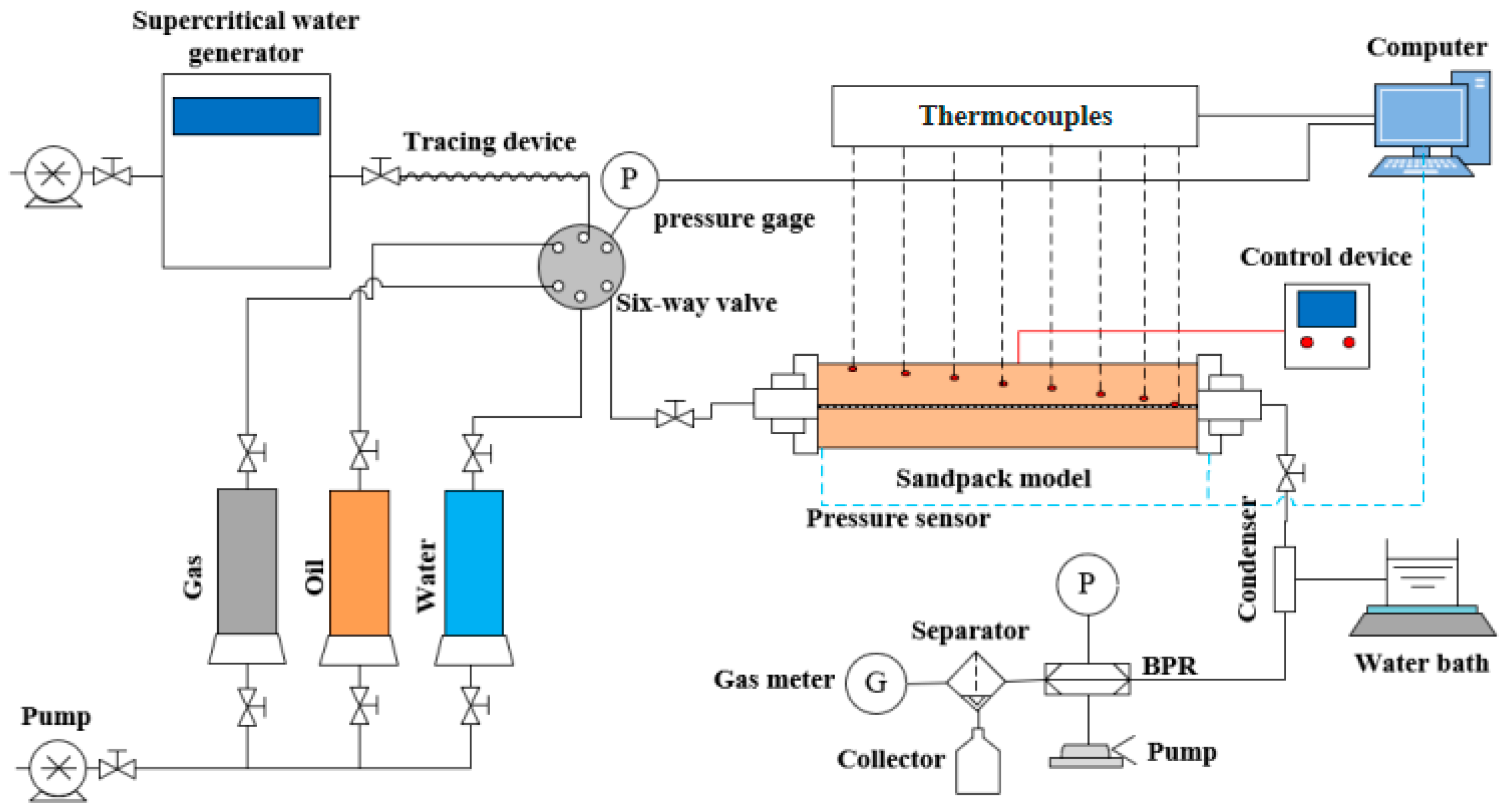
2.2. Experimental Apparatus

The one-dimensional supercritical multi-source, multi-component thermal fluid displacement experimental device was independently developed, including the fluid injection system, one-dimensional supercritical multi-source, multi-component thermal fluid sand pack model, measurement and control system, and production and separation system, as shown in Figure 1.
The fluid injection system includes a supercritical water generator (maximum pressure 35.0 Mpa, maximum temperature 450 °C), a high-pressure plunger pump, and a high-pressure intermediate vessel loaded with heavy oil, formation water, and supercritical CO2 and supercritical N2. Specific parameters of the experimental instruments are shown in Table 3. The supercritical water generator uses a 30 m long Hastelloy coil for heating. The first stage involves heating cold water to approximately 200 °C to produce wet steam, while the second stage is to heat the wet steam to about 350 °C dry steam, and the third stage is to further heat the dry steam to around 450 °C to produce superheated steam. In addition, a heat tracing device is added on to the connecting pipeline between the outlet of the supercritical water generator and the interface of the injection model to prevent loss of steam heat through the output pipeline.
The sand-filled tube model is made of Hastelloy C276, the inner diameter is 3.9 cm, the length is 48 cm, and the maximum working pressure is 50 Mpa and 450 °C. There are six belt heaters (1500 W) on the surface of the model. Prior to each set of experiments, a belt heater is used to maintain the formation temperature, and when steam or hot water is injected, the belt heater heats the model surface to compensate for heat loss. Compared to existing sand-filled models, six belt heaters can independently compensate for heat loss in the area, which is more precise and flexible. In addition, the model is equipped with a thermal insulation jacket, which can further reduce the heat loss of the model to the external environment.
The measurement and control system includes a temperature sensor and pressure sensor, and the computer automatically records the temperature and pressure measured by the temperature and pressure sensor in real time, so as to analyze the thermal recovery process. The temperature probe has an accuracy of ±1 °C in the range of 0 °C to 900 °C, and the pressure sensor has an accuracy of ±1 kPa in the range of 0 MPa to 30 MPa.
The output end is equipped with an automatic separation and metering device, which can automatically separate the output end fluid into the liquid phase and gas phase, and automatically transmit the liquid phase volume and quality of the output end to the data analysis system.

2.3. Experimental Process

Silica sand was poured into a clean one-dimensional core experimental model. After connecting the experimental device, the air tightness check and vacuum were completed. The temperature control system band heater heated the core model to 50 °C (reservoir temperature), following which water and heavy oil were injected into the sand-filled model to simulate the actual reservoir environment. Once the core model was prepared, supercritical water was injected into the model using a supercritical water generator at a certain injection speed, along with an injection of supercritical gas mixture at a specific rate. When the temperature of the one-dimensional supercritical multi-source, multi-component thermal fluid displacement model stabilized, injection was stopped. Each cycle involved 2 h for steam injection and production time. Model parameters and cumulative oil production were recorded in order to calculate displacement efficiency. This process was repeated multiple times with variations in injection temperature, pressure, PV number, and injection speed for numerous tests.

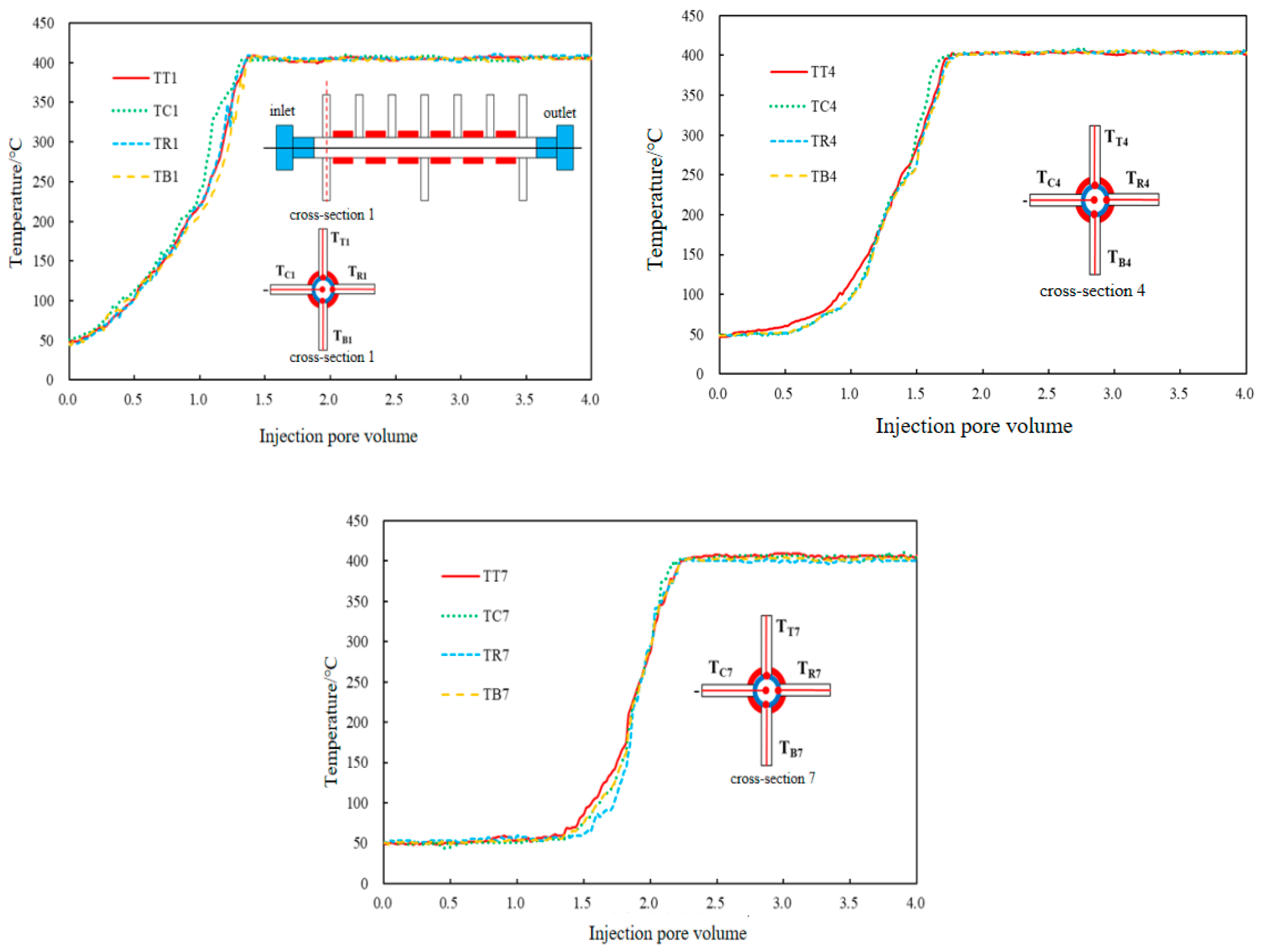
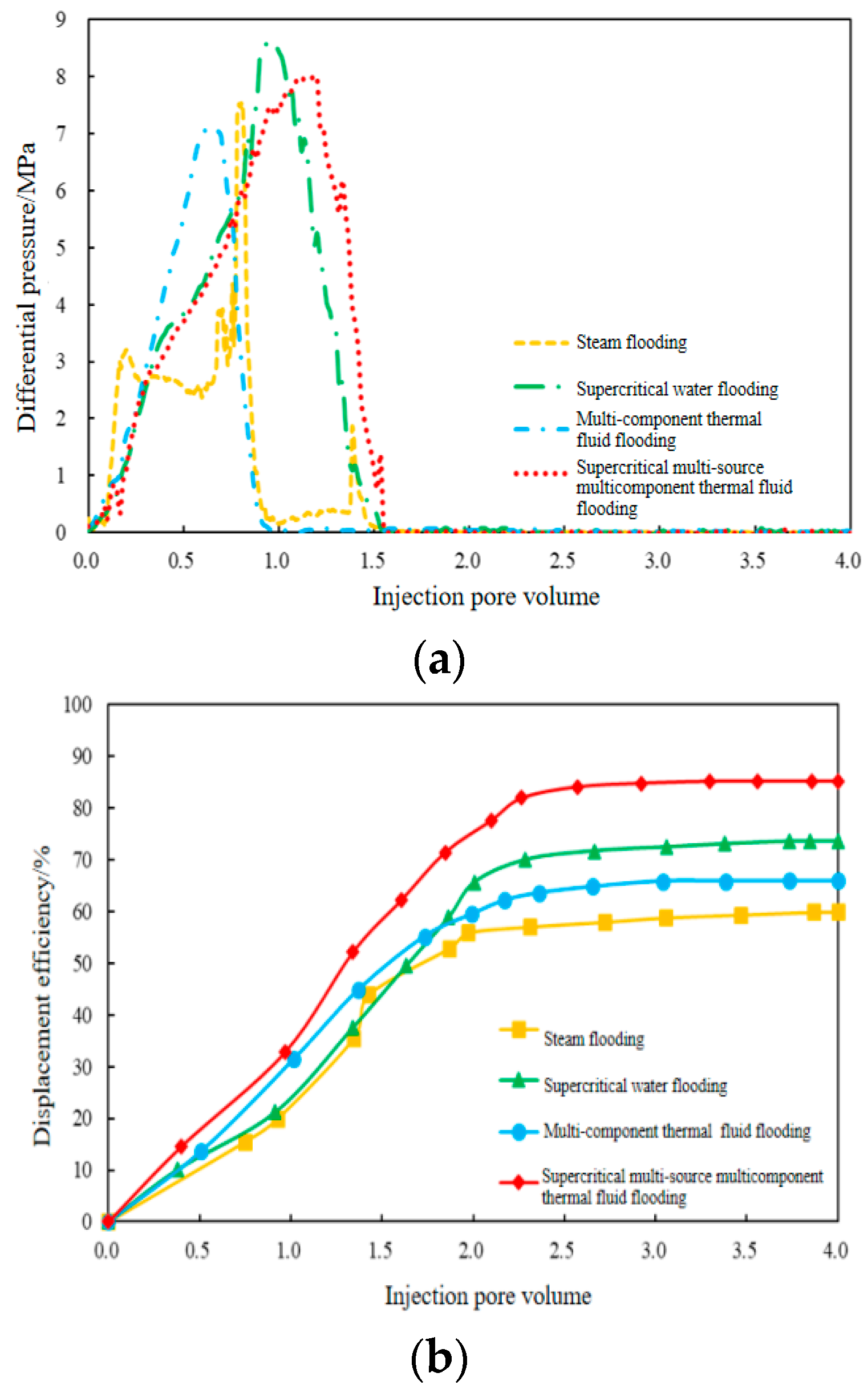
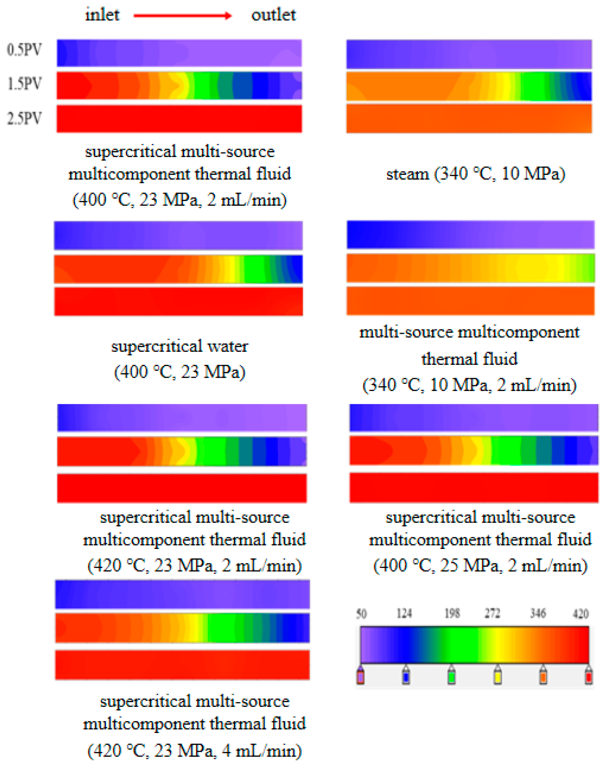
2.4. Experimental Results and Discussion

Currently, the percolation characteristics, production effect, and temperature and pressure distribution in supercritical multi-source, multi-component thermal fluid flooding are still unclear. Therefore, further analysis of the displacement characteristics of supercritical multi-source, multi-component thermal fluid was conducted through Experiment 13. In Experiment 13, a total of 4 PV (pore volume) supercritical multi-source, multi-component thermal fluids were injected. The experimental temperature distribution, pressure difference, and production curve are illustrated in Figure 2, Figure 3 and Figure 4.
As shown in Figure 2, the supercritical multi-source, multi-component thermal fluid displacement process can be delineated into three stages. During the initial phase of displacement (0–1.1 PV), upon injection, the temperature at measuring points TC1 to TC4 near the inlet rose rapidly. It is noteworthy that TC1’s temperature gradually increased, reaching 400 °C at this stage. The temperatures of the three measuring points on vertical plane 1 (Figure 3) were essentially identical, indicating uniform heating (with TC1 registering the highest temperature) due to rapid vertical heat transfer resulting from high injection temperature and a small vertical area. At this stage, the supercritical multi-source, multi-component thermal fluid significantly augmented the flow capacity of heavy oil near the inlet. However, despite this enhancement, the model’s exit temperature remained relatively low, leading to low oil flow capacity at the outlet and consequently causing a sharp increase in the inlet–outlet pressure differential during this stage (Figure 4).
In the middle stage of displacement (1.1–1.5 PV), with the continuous injection of supercritical multi-source, multi-component thermal fluid, the heating range gradually expanded, and the heating front basically reached the exit of the sand-filled model. Therefore, the temperature of TC1-TC3 measuring points reached 400 °C, and the temperature of TC4-TC7 measuring points began to rise (Figure 2). At this time, the heavy oil flow capacity increased and consequently, the heavy oil displacement efficiency began to rise rapidly. Vertical surfaces 1 and 4 exhibited a uniform temperature distribution (Figure 3). However, in vertical plane 7, there was non-uniformity in temperature distribution where TT7 was higher than TB7. The reason for this phenomenon may be that the supercritical multi-source, multi-component thermal fluid produces the overlap phenomenon, and a small amount of supercritical multi-source, multi-component thermal fluid moves to the top of the sand-filled model due to the action of gravity.
In the late displacement stage (1.4–5.0 PV), the maximum heating range was achieved, with the temperature at each measuring point reaching 400 °C (Figure 2 and Figure 3) After the breakthrough of the supercritical multi-source, multi-component thermal fluid, the pressure difference of the inlet and outlet was basically stable, and the cumulative gas production increased sharply. Consequently, the growth rate of oil displacement efficiency in this stage slowed down. The above reasons indicate that supercritical multi-source, multi-component thermal fluid breakthrough has adverse effects on heavy oil production.
As illustrated in Figure 4 and Table 4, the displacement efficiency reached as high as 85.15% when the injection volume of supercritical multi-source, multi-component thermal fluid reached the end of 4 PV. Furthermore, the light color of the cross-section of the inlet and outlet indicated a low remaining oil saturation in the model after supercritical multi-source, multi-component thermal fluid displacement. A comparison of the inlet and outlet cross-sections revealed similar remaining oil saturations due to the high sweep range and displacement efficiency. Therefore, it can be concluded that supercritical multi-source, multi-component thermal fluids have significant potential in offshore heavy oil development.
As can be seen from Figure 4 and Table 5, the displacement efficiency of Experiments 1, 4, 7, and 13 were 59.87%, 73.48%, 78.52%, and 85.15%, respectively. It can be seen that compared with steam flooding, supercritical water flooding, and supercritical water and gas, the development effect of supercritical multi-source, multi-component thermal fluid flooding was better. In addition, it can be seen from Table 4 that the color of the end face of the entrance and exit of Experiment 13 is lighter than that of Experiments 1, 4, and 7, indicating that Experiment 13 has the lowest remaining oil saturation.
By comparing the oil displacement efficiency, heat utilization rate, and core end color of Experiment 1, and Experiment 4, it can be seen that supercritical water displacement effect is better than steam. The reason is that supercritical water has a stronger effect on the upgrading of heavy oil, and it is not easy to produce overlap breakthrough phenomenon. Compared with steam, supercritical water thermal cracking reaction can significantly reduce the viscosity, density and molecular weight of heavy oil, and inhibit the formation of coke. In addition, compared with steam, supercritical water can dissolve weakly polar substances in heavy oil effectively, resulting in miscible flooding effect.
By comparing the results of Experiments 13 and 4 (Figure 4 and Table 5), it can be seen that the presence of supercritical N2 + CO2 is helpful to improve the oil displacement efficiency and relative heat utilization rate of supercritical water flooding and reduce the remaining oil saturation. Therefore, supercritical N2 and supercritical CO2 play an important role in heavy oil production. In addition, it can be seen from Figure 5 that after the injection of 1.5 PV, the advance of the supercritical multi-source, multi-component thermal fluid front is slower than that of the supercritical waterfront. Therefore, the injection of supercritical N2 and CO2 can effectively inhibit the breakthrough of supercritical water. This is due to the large amount of supercritical CO2 dissolved in heavy oil, resulting in heavy oil expansion, and reducing the viscosity, density, and molecular weight of heavy oil.

3. Adaptability Analysis of Supercritical Multi-Source, Multi-Component Thermal Fluid Development

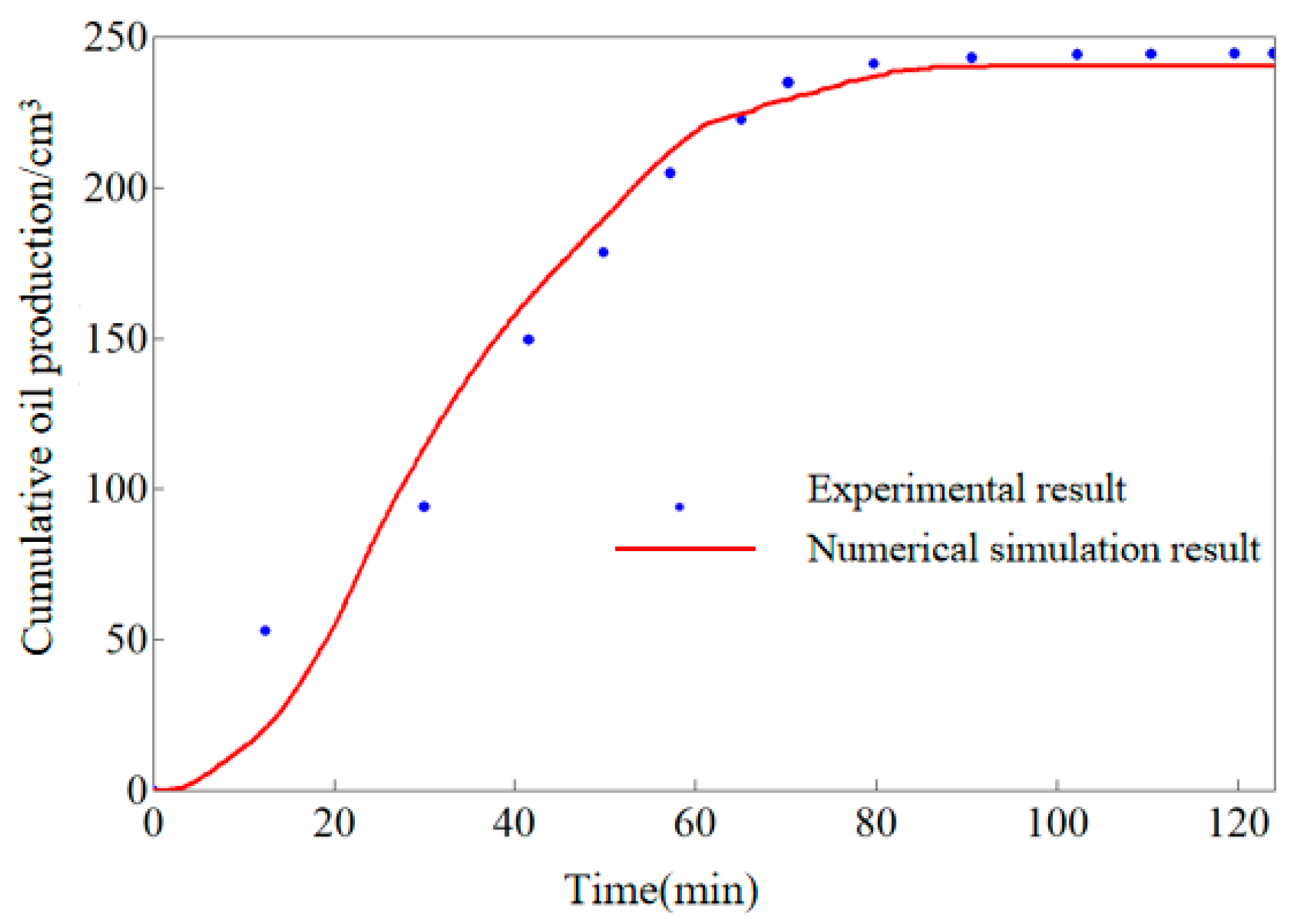
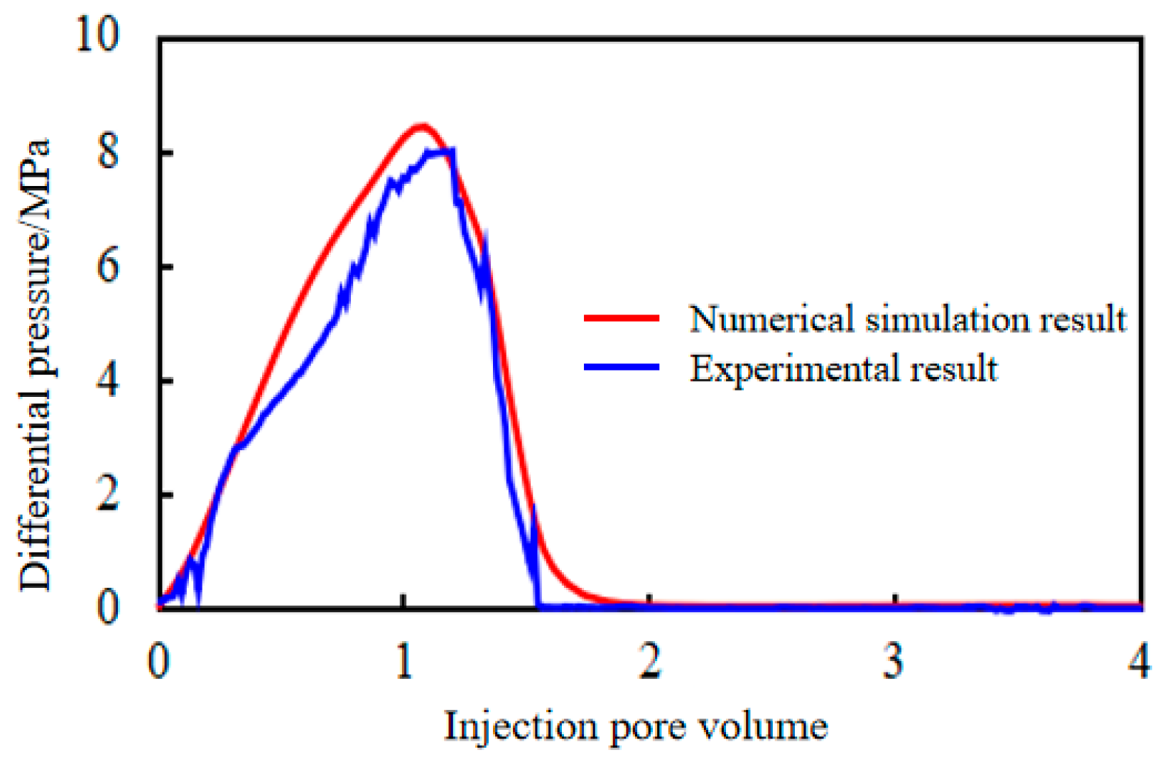
3.1. Establishment of Numerical Simulation Model of Supercritical Multi-Source, Multi-Component Thermal Fluid

In the numerical simulation study, the STARS module, a Canadian CMG (2022 version) numerical simulation software, was adopted to simulate the one-dimensional displacement experiment of supercritical multi-source, multi-component thermal fluid. Experimental parameters and results are shown in Section 2, and a one-dimensional numerical simulation model was established, as shown in Figure 6. In order to improve the accuracy of numerical simulation, the size and number of grids were adopted as the extreme value that the computer could perform convergence operations. The number of grids was 48 × 19 × 19 (17,328), and the size of the grids was 1 cm (X) × 0.2 cm (Y) × 0.2 cm (Z). The dissolution capacity of the gas was characterized by the K-value relation. The reaction kinetic parameters were characterized according to the key Aronius parameters fitted by one-dimensional physical simulation experiments.
The model adopted constant pressure production, and considering the reliability of the model parameters, the following parameters adjustment principles were determined when fitting the experimental production data: since the experimental core size, porosity, permeability, production dynamics, production conditions, etc., are known parameters in the experiment, in principle, the above parameters should not be adjusted during the fitting process; the oil-water relative permeability curve, gas–liquid pair permeability curve, and chemical reaction rate (including reaction activation energy and pre-exponential parameters) have high uncertainties in the model, so the parameters are adjusted in order to fit the process.
According to the above fitting principles, the fitting results of the one-dimensional displacement experiment are shown in Figure 7, Figure 8 and Figure 9 by repeatedly adjusting the uncertain parameters. As shown in Figure 7, the experimental cumulative oil production is 244.36 g, the fitting result is 240.13 g, and the average error of 3.24% is less than 5%. Figure 8 and Figure 9 show that the temperature field and pressure difference curves of the model are basically consistent with the actual conditions, which proves the reliability of the established model.

3.2. Reservoir Adaptability Evaluation

3.2.1. Evaluation Principle

In order to assess the development adaptability of supercritical multi-source, multi-component thermal fluids, a numerical simulation mechanism model was utilized. The physical property parameters in the mechanism model are presented in Table 6. The primary control factors of reservoir static parameters and dynamic parameters were evaluated separately (Table 7 and Table 8), and all relevant parameters were based on the actual parameter distribution range of the Bohai oil field. There are two evaluation methods. The first method is the cumulative oil production evaluation method, which calculates the cumulative oil production after the direct injection of supercritical multi-source, multi-component thermal fluid without considering reservoir fracture pressure. The second method is the cumulative increased oil production evaluation method, which takes into account the fracture pressure of reservoirs with different buried depths, as well as the increased oil production from supercritical multi-source, multi-component thermal fluid injection after cooling and depressurizing pressure, and saturated steam development as the basis for evaluation.
The main control factors were evaluated using the orthogonal test method, a de-sign approach for studying multiple factors and levels [30,31]. In this study, SPSS 26 software was used to conduct an orthogonal experimental design of static parameters and dynamic parameters. The simulation results of cumulative oil production and cumulative increased oil production from supercritical steam huff and puff numerical simulation were utilized as evaluation criteria. General linear univariate analysis was performed on the static and dynamic simulation results separately to investigate the impact of static parameters and dynamics on the development outcomes of supercritical steam huff and puff. The main control parameters for both static and dynamic conditions were defined.

3.2.2. Influence Parameter Evaluation

(1)
Static parameter evaluation
The static parameters of supercritical multi-source, multi-component thermal fluid reservoir were evaluated, including formation oil viscosity, reservoir permeability, reservoir pressure, water multiple, and reservoir thickness. Significance level refers to the probability that the estimated population parameters fall within a certain interval and may make mistakes. DOF represents the number of degrees of freedom, which is the number of variables that can take an unlimited value when calculating a unified measurement. The larger the F-value of the parameter, the higher the degree of influence and the lower the significance level [32]. From the orthogonal test results (Table 9 and Table 10), it can be seen that reservoir pressure and reservoir thickness are the main factors affecting the development effect of supercritical technology, regardless of the cumulative oil production evaluation method or the cumulative increased oil production method, with high significance level and F-value less than 0.05. This is because the formation energy becomes stronger after the reservoir pressure increases. With the increase in reservoir thickness, the reserves and drainage area become larger.
(2)
Dynamic parameter evaluation
When carrying out a dynamic parameter evaluation of supercritical multi-source, multi-component thermal fluid reservoir, the evaluation parameters include the cyclic steam injection volume, the temperature of the steam injection, the speed of the steam injection, the gas–liquid ratio, and the liquid production volume. According to the orthogonal test results (Table 11 and Table 12), both the oil production evaluation method and the oil increase method are highly significant, with an F-value of less than 0.05.
Based on the analysis results of the main control factors of static parameters and dynamic parameters, influence degree charts of the main control factors were established, as shown in Figure 10, which provided a reference for the analysis of the development effect of supercritical multi-source, multi-component thermal fluid variable parameters.
(3)
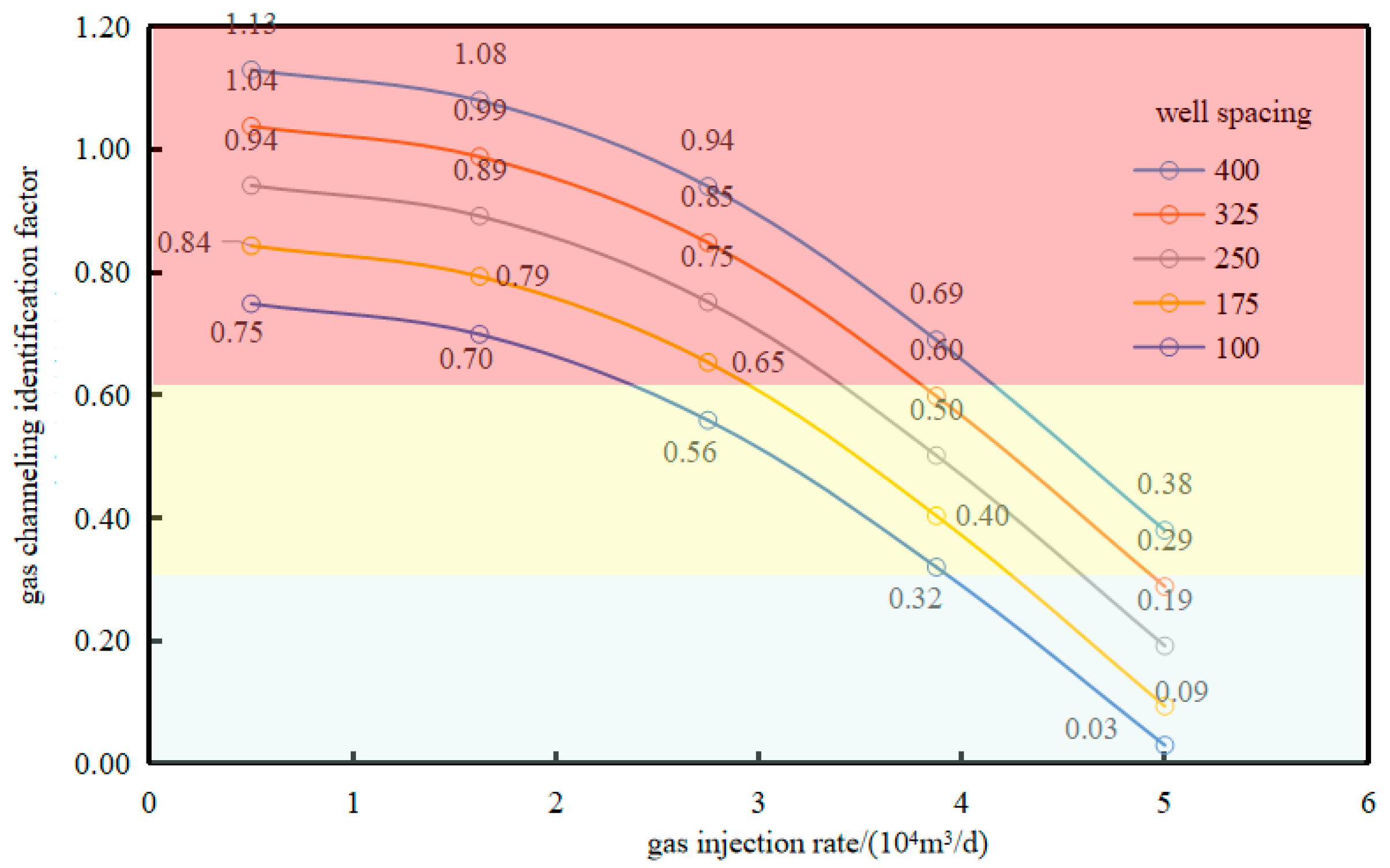
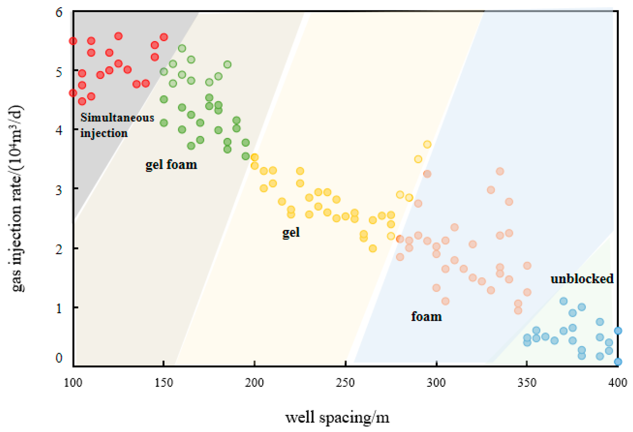
Analysis of the impact degree of associated flue gas channeling and suggestions on control measures
Supercritical multi-component thermal fluid technology will inject an extremely large amount of non-condensate gas (N2 + CO2) when injecting high-temperature water. According to the implementation experience of NB 35-2 field in the Bohai oil field, the injection of non-condensate gas will cause gas channeling and seriously affect the development effect, so it is necessary to analyze the influence degree of channeling flow and study the limits and means of channeling prevention.
Therefore, “cross-flow coefficient” is introduced to quantitatively characterize the degree of cross-flow, which provides a design basis for the application of supercritical technology for offshore heavy oil thermal recovery. According to the factors that may affect gas channeling, the main control factors are screened, the channeling influence chart is established, and the injection mode of experimental and industrial prototypes is optimized.
Considering the main and secondary factors of screening and based on the reservoir fluid parameters of different types of reservoirs, the supercritical multi-source, multi-component thermal fluid gas channeling warning chart after cooling and pressure reduction was established (Figure 11). The gas channeling identification factor (Formula (1)) of the change rate of injection of non-condensate gas is derived.
C = μ m t s μ o t s M R t s t i Ω ϕ S o i S o r H w t s + x L v t s E h s ρ s p s M R t s t i
In the formula, C is the gas channeling identification factor; C < 0.36 means strong gas channeling, 0.36 < C < 0.60 means weak steam channeling, and C > 0.6 means non-steam channeling; ps and pt are saturated steam pressure and temperature; μm(ts) is the viscosity of the mixed fluid; μo(ts) is the mixed viscosity at the front edge of the cavity; ρs(ps) is the density of the mixed fluid; Hw(ts) is the enthalpy of saturated liquid phase; x is steam dryness; Lv(ts) is the latent heat of steam; ti is the original reservoir temperature; Ω is the permeability stage difference; Sor(ts) is the residual saturation of mixed fluid after injection; Ehs is the thermal efficiency of the top and bottom cover; and MR is the reservoir volumetric specific heat capacity.
The introduced cross-flow identification plate was brought into the actual development effect of multi-component thermal fluid huff and puff in NB35-2 oilfield to verify the accuracy of the plate. The verification results are shown in Table 13.
Based on the “Latin Hypercube” multi-factor orthogonal experiment, with oil production as the optimization objective and channeling coefficient as the independent variable, the active channeling prevention methods under different channeling coefficients are investigated, and the proposed active channeling prevention methods with different channeling coefficients are drawn (Figure 12). As can be seen from the Figure 12, the larger the well spacing and the smaller the gas injection rate, the smaller the probability of steam channeling, and no plugging is necessary at this time. The smaller the well spacing and the higher the steam injection rate, the more easily steam channeling occurs. In this case, two gas injection wells can be used to simultaneously inject gas to reduce the risk of steam channeling.

4. Evaluation of Application Potential of Supercritical Technology in Offshore Heavy Oil Reservoirs

Based on the evaluation method of main control factors and the evaluation method of supercritical fluid adaptability, three kinds of evaluation methods for the development and application potential of supercritical multi-source, multi-component thermal fluid was established, namely, the evaluation method of cumulative oil production of a single well, the evaluation method of cumulative increased oil production, and the evaluation criteria of supercritical thermal fluids after cooling and depressurizing. The application potential of supercritical technology in China’s offshore heavy oil was analyzed by a potential evaluation method. The geological parameters of offshore heavy oil reservoirs are shown in Table 14.

4.1. Cumulative Oil Production Evaluation Method

By using a multiple linear regression method, a multiple regression model was established between y function of adaptability evaluation of different reservoir types and key parameters such as oil viscosity, reservoir permeability, reservoir pressure, and reservoir thickness; the formula is shown in Formula (2). Based on the cumulative oil production evaluation method, the application potential of supercritical technology in offshore heavy oil reservoir is ranked (Table 15).
y = −0.00114 a + 0.00084 b + 0.53766 c − 0.11004 d + 0.22176 e + 0.49122
In the Formula (2), y is the cumulative oil production, 104 m3; a is the formation oil viscosity, cP, b is reservoir permeability, mD, c is the reservoir pressure, MPa, d is the multiple of water, and e is the effective reservoir thickness, m.

4.2. Cumulative Increased Oil Production Evaluation Method

By using a multiple linear regression method, a multiple regression model was established between y function of adaptability evaluation of different reservoir types and key parameters such as oil viscosity, reservoir permeability, reservoir pressure and reservoir thickness. Based on the cumulative increased oil production evaluation method, the application potential of supercritical technology in offshore heavy oil reservoir is ranked (Table 16).
y = −0.000892 a + 0.00034 b + 0.182 c − 0.154 d + 0.061 e + 1.053
In the Formula (3), y is the cumulative increased oil production, 104 m3, a is the formation oil viscosity, cP, b is reservoir permeability, mD, c is the reservoir pressure, MPa, d is the multiple of water, and e is the effective reservoir thickness, m.
The cumulative oil production and cumulative oil increase evaluation methods were used to grade the application potential of the reservoir. The evaluation criteria are as follows: Class I reservoirs: cumulative oil production > maximum cumulative oil production × 60.5%, including LD 21-2 IV oil group, LD 16-3, etc. Class II reservoirs: maximum accumulative oil production × 60.5% > accumulative oil production > Maximum accumulative oil production × 31.3%, including LD 27-2, etc. Class III reservoirs: the highest accumulative oil production × 31.3% > accumulative oil production, including LD 32-2, and so on. Of the 670 million tons of proven offshore heavy oil reserves, Class I reserves adapted to supercritical technology reach 280 million tons, Class II reserves reach 160 million tons, and Class III reserves reach 220 million tons.

4.3. Adaptive Screening Evaluation Method

4.3.1. Establishment of Economic Boundary Evaluation Model

Compared with conventional development, the investment of supercritical development is larger, and the price of heavy oil is lower than that of light oil, so it is necessary to determine the minimum economic oil production limit as the basis for development. The minimum oil production is calculated according to the input–output method. When the economic benefit of input and output is 0, the oil production obtained is the minimum oil production limit.
Q m i n = C f o n P 0 R 0 ( 1 T a x o ) C v o
In Formula (4), Qmin is the lowest oil production, 10 thousand tons; Cfon is the additional drilling and surface investment, 10 thousand dollars; Po is the oil price, 10 thousand dollars; Ro is the crude oil commodity rate; Taxo is the comprehensive tax rate; and Cvo is the operating cost, 10 thousand dollars. Among them, the crude oil price is calculated according to 60 USD/barrel, the comprehensive tax rate is 7%, and the operating cost adopts the average reference design of the current offshore thermal production oil field.
Combined with the current offshore oilfield development engineering scale [33,34], the engineering of offshore heavy oil developed by supercritical fluid injection can be divided into two conditions: (1) Relying on development, building the new offshore wellhead platform and mixed transmission manifolds, and relying on other oilfields central processing platforms for power and oil processing. (2) For further exploitation, considering the technical maturity of supercritical technology, the technology is applied in the production field, and the further development is explored by using the original platform.

4.3.2. Establishment of Adaptive Screening Criteria

(1)
Relying on development screening criteria
The investment of the new wellhead platform is 600 million yuan, and the cycle operation cost is consistent with the multi-component thermal fluid. In this model, the development scale and investment of supercritical technology is close to that of mature multi-component thermal fluid technology, and the injection and production integrated string is adopted. According to the calculation of Formula (4), if the economic development of supercritical technology is realized, the oil increase of 8 cycles of supercritical huff and puff should not be less than 59,000 cubic meters per single well. Basic evaluation parameters are shown in Table 17.
(2)
For further exploitation screening criteria
With reference to the offshore platform floor flue gas reinjection scheme, the initial engineering facility investment is 140 million yuan without considering the replacement of thermal production string and the cycle operation cost is consistent with other thermal production methods. According to Formula (4), if the economic development of supercritical technology is to be realized, the oil increase in 8 cycles of supercritical huff and puff should not be less than 0.93 million cubic meters per single well. Basic evaluation parameters are shown in Table 18.

4.4. Development and Application Potential Evaluation Based on Different Evaluation Methods

Based on the comparison of steam huff and pressure drop of supercritical fluid after different reservoir types and different reservoir fluid parameters, combined with the simple evaluation economic model, the screening criteria of supercritical thermal fluid application after temperature drop and pressure drop under different reservoir types and different engineering models are given (Table 19).
Through the cumulative oil production evaluation method, cumulative increased oil production evaluation method, and adaptive screening criteria method, the three methods were integrated. A total of 6 oil fields with the most application potential were selected, respectively:
(1)
LD 21-2 IV oil group;
(2)
PL 19-3 11/13 area;
(3)
KL 10-2;
(4)
QHD 27-3;
(5)
KL 16-1 2 well area;
(6)
LD 21-2 V oil group.
The total proved reserves are 96 million tons, of which the single sand-body reservoir is the main reservoir, accounting for 84% of the reserves.

5. Design of Supercritical Technology Pilot Test Area

5.1. Overview of Pilot Test Area

The pilot test area was selected KL10-2 oilfield. KL10-2 oilfield is located in the south of Bohai Sea. The oil bearing layers are mainly in the lower Ming Member IV and V oil groups, and the reservoir thickness is 3~17 m. The porosity is 30%, the permeability is 2906 mD, and the crude oil viscosity is 328~604 mPa·s.
The ODP program designed 24 thermal recovery wells, which were developed by chemical assisted steam flooding after 8 rounds of steam huff-puff, with a reserve of 18.8776 million square meters, a peak production capacity of 428,000 square meters, and a cumulative oil production of 3.166 million cubic meters with a recovery rate of 18.8%.

5.2. Pilot Test Well Plan

(1)
Injection parameters: Considering the supercritical multi-source, multi-component hot fluid injection after cooling and depressurization, the design wellhead injection pressure is 15.7 MPa, injection temperature is 353 °C, daily gas injection is 5000 m3/d, and 4 wells are used for simultaneous injection and foam sealing channeling technology.
(2)
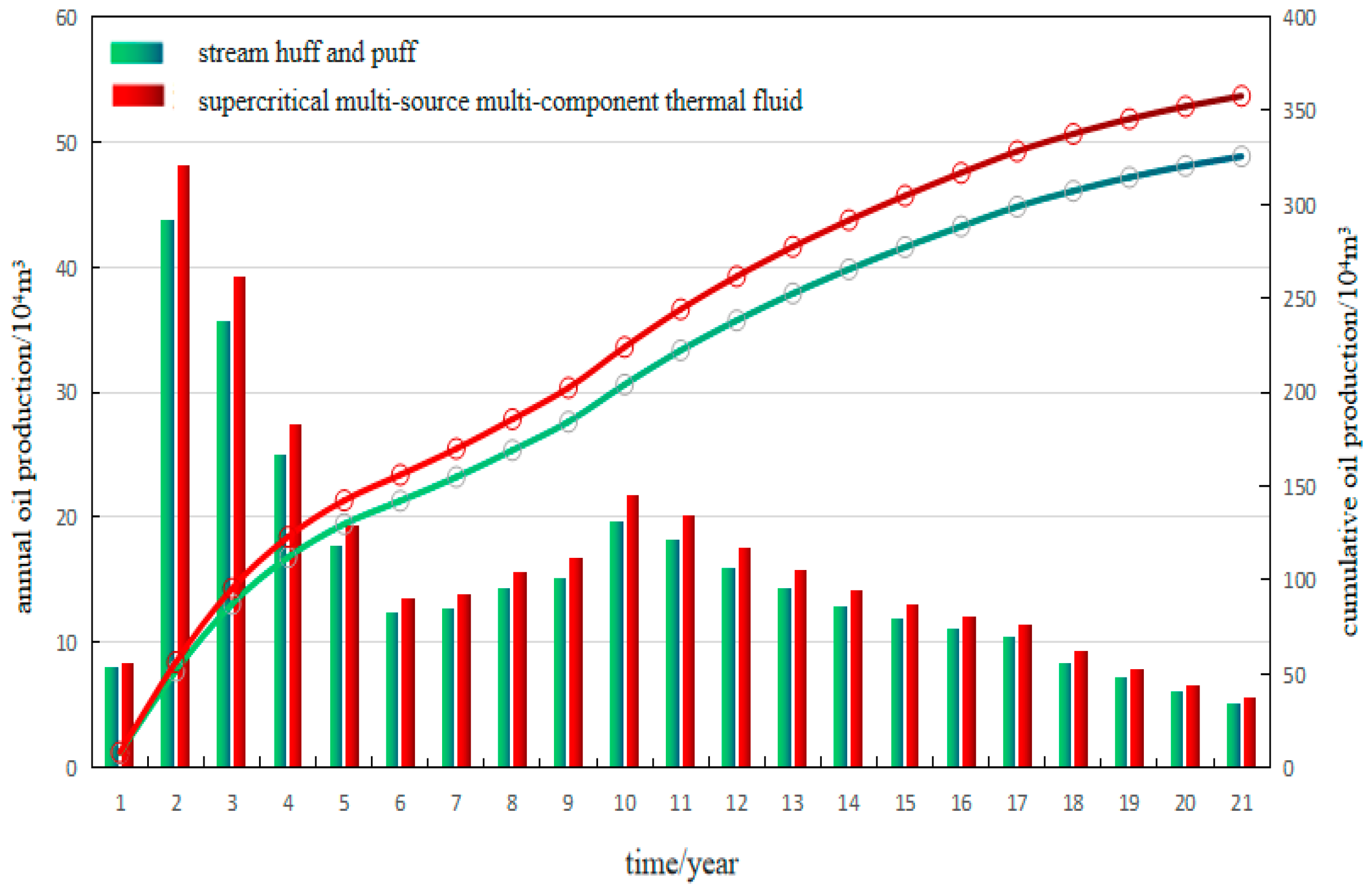
Index prediction: The predicted production profile of the supercritical technology in KL10-2 oilfield is shown in Figure 13. The bars in the figure represent the annual oil production, while the points and lines depict the cumulative oil production. A total of 24 thermal production wells were designed to carry out the development of supercritical multi-source multi-component thermal fluid huff and puff/sidetrack/transfer supercritical multi-component thermal fluid flooding, and the cumulative oil production of the platform was predicted to be 3.57 million cubic meters with a recovery rate of 20.6%. Compared with steam huff and puff development, the oil increase is 404,000 square meters, and the oil increase is 17,000 square meters per well.

6. Conclusions

(1)
Supercritical multi-source, multi-component thermal fluid offers the advantages of high temperature, high dryness, and a high heating utilization rate. And supercritical fluid technology can economically and efficiently treat organic waste liquid, making it highly applicable in offshore heavy oil exploitation and environ-mental governance with great prospects for application.
(2)
A numerical simulation model considering four groups of seven components was established, and the simulation accuracy was over 95%. Based on the fitted numerical simulation model of supercritical fluid reservoir, the evaluation of the main control factors under different injection parameters of single sand reservoir was carried out, and the influence degree chart of the main control factors under the influence of static and dynamic parameters was established by using the single well cumulative oil production method.
(3)
Through orthogonal test and numerical simulation, the sequencing of main controlling factors affecting the development of supercritical multi-source multi-component thermal fluids in heavy oil offshore was clarified, and the influencing chart of gas channeling degree and the suggested chart of gas channeling control measures were established.
(4)
The application potential of 670 million tons of heavy oil reserves in the Bohai oil field was sorted based on oil production evaluation, oil increase evaluation and adaptive screening standard methods, and the reserves suitable for supercritical technology reached 280 million tons. Taking KL 10-2 oilfield as an example, after replacing the traditional steam boiler with supercritical technology, the residual production increased by 404,000 cubic meters and the recovery rate increased by 1.8%, which verified the great potential of this technology in the overall promotion of offshore.

Author Contributions

As the first author, Y.S. wrote the main manuscript text. L.Z. and Y.B. are the main authors of the review and completed the collection and analysis of the relevant literature. T.W., W.Z., and J.Z. participated in the analysis and sorting of the literature materials and contributed to the review and editing of this work. As the corresponding author, P.L. made substantial contributions to the conception/design of the work and approved the final version to be published. All authors have read and agreed to the published version of the manuscript.

Funding

The authors declare that this study received funding from the “14th Five-Year” major science and Technology Project (Effective Development Technology of Offshore Heavy Oil Thermal Recovery) of China National Offshore Oil Co., Ltd.

Institutional Review Board Statement

Not applicable.

Informed Consent Statement

Not applicable.

Data Availability Statement

The original contributions presented in the study are included in the article, further inquiries can be directed to the corresponding author.

Acknowledgments

The authors would like to thank the research team members for their contributions to this work.

Conflicts of Interest

Yan Sun was employed by the company CNOOC Research Institute Co., Ltd (Beijing China). The remaining authors declare that the research was conducted in the absence of any commercial or financial relationships that could be construed as a potential conflict of interest.

References

  1. Su, Y.; Zheng, W.; Yang, R.; Yu, J.; Yang, Z. Current situation and prospect of thermal recovery in offshore heavy oil fields. China Offshore Oil Gas 2023, 35, 100–106. [Google Scholar]
  2. Sun, P.; Liu, Y. Development status of heavy oil reservoir in Bohai Sea and difficulties and countermeasures of thermal recovery. China Offshore Oil Gas 2023, 35, 85–92. [Google Scholar]
  3. Chen, Y. Evaluation of steam huff and puff development effect in onshore A heavy oil reservoir and challenges of thermal production in offshore heavy oil field. China Offshore Oil Gas 2011, 23, 384–386. [Google Scholar]
  4. Zhu, J.; Yu, J.; Zheng, W. Preliminary study on evaluation of development effect of multi-component thermal fluid huff and puff for offshore heavy oil. J. Southwest Pet. Univ. (Nat. Sci. Ed.) 2016, 38, 89–94. [Google Scholar]
  5. Zheng, W.; Yuan, C.; Tian, J. Effect comparison and optimization of heavy oil in Bohai Sea by different handling methods. Spec. Oil Gas Reserv. 2014, 21, 79–82. [Google Scholar]
  6. Li, S.; Yang, B.; Zhang, S.; Zheng, W.; Peng, X.; Zhang, W. Research on complex huff and puff production technology of horizontal well in heavy oil reservoir. Reserv. Eval. Dev. 2014, 4, 42–46. [Google Scholar]
  7. Li, F.; Zhang, S.; Ding, M. Test of enhanced recovery technology of flue gas injection in heavy oil huff and puff well. Oil Drill. Prod. Technol. 2001, 23, 67–68. [Google Scholar]
  8. Fan, Y.; Fu, T.; Yin, Y. Research status and development direction of gas-assisted steam huff and puff in heavy oil reservoirs. Reserv. Eval. Dev. 2018, 235, 111–117. [Google Scholar]
  9. Peng, Q.; Zheng, W. Study on the factors affecting the production capacity of offshore heavy oil by multicomponent hot fluid huff and huff—A case study of N Oilfield in Bohai Sea. Pet. Geol. Eng. 2020, 20, 67–70. [Google Scholar]
  10. Zhang, Y.; Song, J.; Ma, H.; Jiang, S. Analysis of influencing factors of flooding heavy oil reservoirs with supercritical carbon dioxide. Geol. Explor. 2017, 53, 801–806. [Google Scholar]
  11. Zhao, X.; Wang, Q.; Cheng, L.M. Dynamic Self-adaptive Simulation for Supercritical Water Gasification of Sludge. Chem. Eng. 2018, 46, 63–66. [Google Scholar]
  12. Qu, M.; Yang, D.; Liang, Z.; Wan, L.; Liu, D. Experimental and Numerical Investigation on Heat Transfer of Ultra-supercritical Water Invertical upward Tube under Uniform and Non-uniform Heating. Int. J. Heat Mass Transfer. 2018, 127, 769–783. [Google Scholar] [CrossRef]
  13. Liu, J.; Xing, Y.; Chen, Y.; Yuan, P.; Cheng, Z.; Yuan, W. Visbreaking of Heavy Oil under Supercritical Water Environment. Ind. Eng. Chem. Res. 2018, 57, 867–875. [Google Scholar] [CrossRef]
  14. Yang, B.; Li, S.; Qi, X.; Shi, H.; Zhu, W. Optimization of multi-component thermal fluid huff and puff production technology for offshore heavy oil reservoirs. Pet. Geol. Eng. 2012, 4, 54–56. [Google Scholar]
  15. Du, Y.; Wang, Y.; Jiang, P. Mechanism and feasibility study of nitrogen assisted cyclic steam stimulation for ultra-heavy oil reservoir. In Proceedings of the SPE Enhanced Oil Recovery Conference, Kuala Lumpur, Malaysia, 2–4 July 2013. SPE 165212. [Google Scholar]
  16. Wang, R. Study on Supercritical Steam Huff and Puff Technology of Ultra-Deep and Ultra-Heavy Oil in East Lukqin Area; China University of Petroleum (East China): Dongying, China, 2015. [Google Scholar]
  17. Onwudili, J.A.P.; Williams, T. Reaction Mechanisms for the Hydrothermal Oxidation of Petroleum Derived Aromatic and Aliphatic Hydrocarbons. J. Supercrit. Fluids 2007, 43, 81–91. [Google Scholar] [CrossRef]
  18. Liu, D.; Hu, H.; Pan, M.; Wu, J.; Zhang, J. Comparison of the mining effect of multi-component thermal fluid huff-and-puff and steam huff-and-puff for offshore. Spec. Oil Gas Reserv. 2015, 22, 118–120+157. [Google Scholar]
  19. Liu, Y.; Zou, J.; Wu, W.; Wang, C. Design and Experimental Study of New-Type Supercritical Steam and Flue Gas Generator for Offshore Oilfield. In Proceedings of the International Petroleum Technology Conference, Beijing, China, 26–28 March 2019. ITPC 19055. [Google Scholar]
  20. Li, Y.; Sun, F.; Cai, M. Physical simulation of supercritical multicomponent hot fluid flooding characteristics for heavy oil offshore. Fault-Block Oil Gas Field 2023, 30, 545–551. [Google Scholar]
  21. Taylor, J.D.; Herdman, C.M.; Wu, B.C.; Wally, K.; Rice, F.S. Hydrogen Production in a CoMPact Supercritical Water Reformer. Hydrog. Energy 2003, 28, 1171–1178. [Google Scholar] [CrossRef]
  22. Pinkwart, K.; Bayha, T.; Lutter, W.; Krausa, M. Gasification of Diesel Oil in Supercritical Water for Fuel Cells. Power Sources 2004, 136, 211–214. [Google Scholar] [CrossRef]
  23. Watanabe, M.; Mochiduki, M.; Sawamoto, S.; Adschiri, T.; Arai, K. Partial Oxidation of n-Hexadecane and Polyethylene in Supercritical Water. J. Supercrit. Fluid 2001, 20, 257–266. [Google Scholar] [CrossRef]
  24. García Jarana, M.B.; Sánchez-Oneto, J.; Portela, J.R.; Nebot Sanz, E.; Martínez dela Ossa, E.J. Supercritical Water Gasification of Industrial Organic Wastes. J. Supercrit. Fluids 2008, 46, 329–334. [Google Scholar] [CrossRef]
  25. Morimoto, M.; Sugimoto, Y.; Saotome, Y.; Sato, S.; Takanohashi, T. Effect of Supercritical Water on Upgrading Reaction of Oil Sand Bitumen. J. Supercrit. Fluids 2010, 55, 223–231. [Google Scholar] [CrossRef]
  26. Zhang, J.; Shen, H.; Gao, R. Carbon dioxide gas assisted SAGD physical simulation experiment. Acta Pet. Sin. 2014, 35, 1147–1152. [Google Scholar]
  27. Zhao, Y.; Guo, J.; Wang, C. Study on thermal-physical characteristics of enhanced oil recovery of super-heavy oil by supercritical water flooding. J. Eng. Thermophys. 2020, 41, 635–642. [Google Scholar]
  28. Sun, X.; Li, X.; Tan, X.; Zheng, W.; Zhu, G.; Cai, J.; Zhang, Y. Pyrolysis of Heavy Oil in Supercritical Multi-thermal Fluid: An Effective Recovery Agent for Heavy Oils. J. Pet. Sci. Eng. 2021, 196, 107784. [Google Scholar] [CrossRef]
  29. Rong, X.; Yuan, F.; Meng, F.; Kou, S.; Li, Z. Study on Enhanced oil recovery from offshore super heavy oil reservoirs with supercritical CO2 and steam injection. Petrochem. Ind. Appl. 2022, 41, 16–21. [Google Scholar]
  30. Zhang, S.; Li, J.; Chen, J. Orthogonal optimization design of injection and production parameters of steam huff and puff offshore heavy oil reservoir. J. Chongqing Univ. 2015, 38, 80–85. [Google Scholar]
  31. Zhou, J.; Zhang, Q.; Huang, M. Optimization of injection and production parameters of high period steam huff and puff in heavy oil reservoir based on multi-index orthogonal design. Math. Pract. Theory 2021, 51, 174–180. [Google Scholar]
  32. Janson, L.; Fithian, W.; Trevor, J. Hastie. Effective degrees of freedom: A flawed metaphor. Biometrika 2015, 102, 479–485. [Google Scholar] [CrossRef]
  33. Qin, W. Economic evaluation methods for offshore oil and gas field adjustment and renovation projects. Nat. Gas Ind. 2007, 27, 363–364. [Google Scholar]
  34. Tan, Y. Economic analysis of offshore oilfield development engineering methods. Mod. Econ. Inf. 2015, 30, 426–430. [Google Scholar]
Figure 1. Flow of supercritical multi-source, multi-component thermal fluid displacement experimental device.
Applsci 14 03588 g001
Figure 2. Relationship between temperature and injection volume at each point in the model axis.
Applsci 14 03588 g002
Figure 3. Relationship between temperature and injection volume at inlet face (upper left); mid face (upper right) and outlet face (down).
Applsci 14 03588 g003
Figure 4. Comparison of pressure difference (a) and recovery efficiency (b).
Applsci 14 03588 g004
Figure 5. Temperature field diagram of each experiment.
Applsci 14 03588 g005
Figure 6. One-dimensional numerical simulation mechanism model.
Applsci 14 03588 g006
Figure 7. Fitting results of displacement experiment.
Applsci 14 03588 g007
Figure 8. Comparison of experimental (left) and simulated (right) temperature field results.
Applsci 14 03588 g008
Figure 9. Pressure difference fitting results.
Applsci 14 03588 g009
Figure 10. Static parameters control factors influence degree chart (left) and dynamic parameters control factors influence degree chart (right).
Applsci 14 03588 g010
Figure 11. Warning chart of supercritical multi-source, multi-component thermal fluid gas channeling after temperature and pressure reduction.
Applsci 14 03588 g011
Figure 12. Supercritical fluid injection control chart under different well spacing and gas injection intensity.
Applsci 14 03588 g012
Figure 13. Section diagram of predicted production by supercritical technology in experimental oilfield.
Applsci 14 03588 g013
Table 1. Comparison between supercritical technology and conventional thermal recovery technology.
Technology TypeFuelWater Quality
Requirement
Enthalpy (kJ/kg)Generating Equipment Thermal Efficiency
Supercritical multi-source multi-component thermal fluidHeavy oil, crude oil, diesel oil, heavy oil production waterProduction water or organic wastewater2867.33
(23 Mpaa, 400 °C)
No smoke loss,
low generator temperature
Traditional multi-component thermal fluidDieselHigh water quality requirements1401.41
(270 °C)
High generator temperature
SteamDiesel or crude oilHigh water quality requirements2385.05
(350 °C, steam
quality 80%)
High generator temperature
Table 2. Supercritical multi-source, multi-component thermal fluid experiment scheme.
NumbersInjection FluidsInjection PressuresInjection TemperaturesWater
Injection Rate
N2
Injection Rate
CO2
Injection Rate
1steam10 MPa315 °C10 mL/min0 mL/min0 mL/min
2steam12 MPa330 °C10 mL/min0 mL/min0 mL/min
3steam14 MPa340 °C10 mL/min0 mL/min0 mL/min
4supercritical water23 MPa400 °C10 mL/min0 mL/min0 mL/min
5supercritical water23 MPa374 °C10 mL/min0 mL/min0 mL/min
6supercritical water24 MPa400 °C10 mL/min0 mL/min0 mL/min
7supercritical water + N223 MPa400 °C10 mL/min2 mL/min0 mL/min
8supercritical water + N223 MPa374 °C10 mL/min2 mL/min0 mL/min
9supercritical water + N224 MPa400 °C10 mL/min2 mL/min0 mL/min
10supercritical water + CO223 MPa400 °C10 mL/min0 mL/min2 mL/min
11supercritical water + CO223 MPa374 °C10 mL/min0 mL/min2 mL/min
12supercritical water + CO224 MPa400 °C10 mL/min0 mL/min2 mL/min
13Supercritical multi-source multi-component thermal fluid23 MPa400 °C10 mL/min1 mL/min1 mL/min
14Supercritical multi-source multi-component thermal fluid23 MPa400 °C10 mL/min2 mL/min2 mL/min
15Supercritical multi-source multi-component thermal fluid23 MPa420 °C10 mL/min1 mL/min1 mL/min
16Supercritical multi-source multi-component thermal fluid25 MPa400 °C10 mL/min1 mL/min1 mL/min
Table 3. Parameters of the supercritical water generator.
Experimental Device ParameterIndex
Maximum working pressure35 Mpa
Maximum flow3 kg/h
Maximum temperature450 °C
Maximum superheat>5 °C
MaterialsHastelloy
Coil length30 m
Table 4. Cross-sectional states of inlet and outlet of different injected fluids.
Experiment Number14713141516
Injected fluidsteamSupercritical watersupercritical water + N2supercritical multi-source multi-component thermal fluidsupercritical multi-source multi-component thermal fluidsupercritical multi-source multi-component thermal fluidsupercritical multi-source multi-component thermal fluid
Inlet cross-sectionApplsci 14 03588 i001Applsci 14 03588 i002Applsci 14 03588 i003Applsci 14 03588 i004Applsci 14 03588 i005Applsci 14 03588 i006Applsci 14 03588 i007
Outlet cross-sectionApplsci 14 03588 i008Applsci 14 03588 i009Applsci 14 03588 i010Applsci 14 03588 i011Applsci 14 03588 i012Applsci 14 03588 i013Applsci 14 03588 i014
Table 5. Experimental results of yield increase contribution rate research.
NumberDisplacement EfficiencyHeat Utilization RateNumberDisplacement EfficiencyHeat Utilization Rate
159.87%0.0171979.18%0.0245
261.85%0.01791081.25%0.0252
362.97%0.01841180.08%0.0255
473.48%0.02291282.96%0.0260
570.22%0.02251385.15%0.0267
675.03%0.02331486.16%0.0262
778.52%0.02411592.11%0.0276
876.96%0.02371690.37%0.0274
Table 6. The physical property parameters.
ParametersValue
Reservoir pressure/MPa10
Reservoir temperature/°C50
Core porosity/%39
Core permeability/mD2000
Core oil saturation/%93.5
Gas type15% CO2 + 85% N2
Well typeHorizontal well
Reserve volume/104 m31025
Injection modecontinuous injection
Table 7. Static parameter optimization categories.
NumberStatic ParameterValue Range
1Oil viscosity/mPa·s350~3000
2Permeability/mD300~5000
3Reservoir pressure/Mpa6.5~20
4Water multiple0.1~10
5Reservoir thickness/m6~40
Table 8. Dynamic parameter optimization categories.
NumberDynamic ParameterValue Range
1Periodic steam injection volume/m33000~7000
2Steam injection temperature/°C270~430
3Steam injection rate/(m3/d)90~330
4Gas-liquid ratio/(m3/m3)100~900
5Liquid production/m380~160
Table 9. General linear univariate analysis of static parameters (cumulative oil production).
Static ParametersSum of SquaresDOFMean SquareFSignificance
Oil viscosity0.81240.2030.2000.926
Permeability1.46840.3670.3610.826
Reservoir pressure30.80347.7017.5730.038
Water multiple1.31440.3280.3230.850
Net-to-gross ratio26.53946.6356.5240.048
Table 10. General linear univariate analysis of static parameters (cumulative increased oil production).
Static ParametersSum of SquaresDOFMean SquareFSignificance
Oil viscosity14.58743.6476.0740.054
Permeability5.93441.4842.4710.201
Reservoir pressure15.99643.9996.6610.047
Water multiple10.13942.5354.2220.096
Net-to-gross ratio13.51643.3795.6280.061
Table 11. General linear univariate analysis of dynamic parameters (cumulative oil production).
Dynamic ParametersSum of SquaresDOFMean SquareFSignificance
Periodic steam injection volume1.61240.40322.0940.005
Steam injection temperature2.58840.64735.4590.002
Liquid production0.01640.0040.2210.914
Steam injection rate0.27440.0693.7580.114
Gas-liquid ratio0.2640.0653.560.123
Table 12. General linear univariate analysis of dynamic parameters (cumulative increased oil production).
Dynamic ParametersSum of SquaresDOFMean SquareFSignificance
Periodic steam injection volume0.01440.0048.6680.03
Steam injection temperature0.01740.00410.0380.023
Liquid production0.00440.0012.2320.228
Steam injection rate0.00940.0025.1770.07
Gas-liquid ratio0.00640.0023.7460.114
Table 13. Warning chart of gas channeling after temperature and pressure reduction.
Gas Channeling DegreeGas Channeling Identification FactorMaximum Daily Gas Injection
104 m3/d
/0.85~2.970~1.5
Weak0.51~0.630.75~1.5
Medium0.40~0.601.5~3.0
Strong<0.40>3.0
Table 14. Geological parameters of offshore heavy oil reservoirs.
Oil FieldReservoir Thickness/mReservoir Pressure/MPaWater Energy/timesReservoir Permeability/mDOil Viscosity/cP
LD 21-2 IV oil group4015.31019662980
PL19-3 11/13 area251221161438
KL 10-281313000935
QHD 27-3710.614000440
LD 27-2813.10.123001383
NB 35-288.554600707
PL 13-28.31101957661
LD 27-1811.8016001038
JX 1-11011.651000593
QHD 33-1S510.612078750
KL 9-51010101726910
LD 32-21512.1603130498
Table 15. Evaluation of adaptive screening criteria based on oil production method.
RankSingle Sand Body Oil Fieldy Value
1LD 21-2 IV oil group14.74
2PL19-3 11/13 area12.74
3LD 16-312.19
4KL 10-210.60
5QHD 27-310.49
6LD 27-29.65
7NB 35-29.34
8PL 13-29.14
9LD 27-18.77
Table 16. Evaluation of adaptive screening criteria based on increased oil production method.
RankSingle Sand Body Oil Fieldy Value
1LD 21-2 IV oil group5.33
2PL19-3 11/13 area4.91
3QHD 27-34.54
4KL 10-24.45
5NB 35-24.23
6LD 32-24.07
7LD 27-24.03
8PL 13-23.90
Table 17. Basic evaluation parameter table (Relying on development).
Evaluation ParametersValue
Well-controlled reserves500,000 cubic meters
Development modeSupercritical fluid after cooling and depressurization
Mechanical mining methodIntegrated injection-production string
Single platform development investment65 million yuan
Single well drilling and completion investment40 million yuan
Operating cost per well cycle5 million yuan
Table 18. Basic evaluation parameter table (For further exploitation).
Evaluation ParametersValue
Horizontal well length400 m
Development modeMulti-component thermal fluid/Steam huff and puff/Supercritical fluid after cooling and depressurization
Mechanical mining methodIntegrated injection-production string
Investment in engineering facilities140 million yuan
Average investment per well15 million yuan
Operating cost per well cycle5 million yuan
Table 19. Development adaptation screening criteria for different development methods.
NumberReservoir/Fluid ParametersScreening Criteria
Potential Tapping
Development
Developing Relying on Other
Developing Oilfield
1Reserve scale/104 m3≥500≥1400
2Reservoir buried depth/m≥1000≥600
3Reservoir pressure/MPa≥10≥6
4Reservoir thickness/msingle layer 10
multi-layer/thick layer30
single layer ≥ 5
transitional zone ≥ 20
multi-layer/thick layer ≥ 25
5NTG≥0.6≥0.6
6Gas channeling
identification factor
≥0.6≥0.6
7Vertical permeability ratio0.05~0.40.05~0.4
8Water energypure oil region ≤ 10pure oil region ≤ 20
transitional zone ≤ 5
9Permeability/mD≥1000≥500
10Oil viscosity/cP≥500≥300
Disclaimer/Publisher’s Note: The statements, opinions and data contained in all publications are solely those of the individual author(s) and contributor(s) and not of MDPI and/or the editor(s). MDPI and/or the editor(s) disclaim responsibility for any injury to people or property resulting from any ideas, methods, instructions or products referred to in the content.

