
Study on the Impact of Different Pile Foundation Construction Methods on Neighboring Oil and Gas Pipelines under Very Small Clearances

Abstract
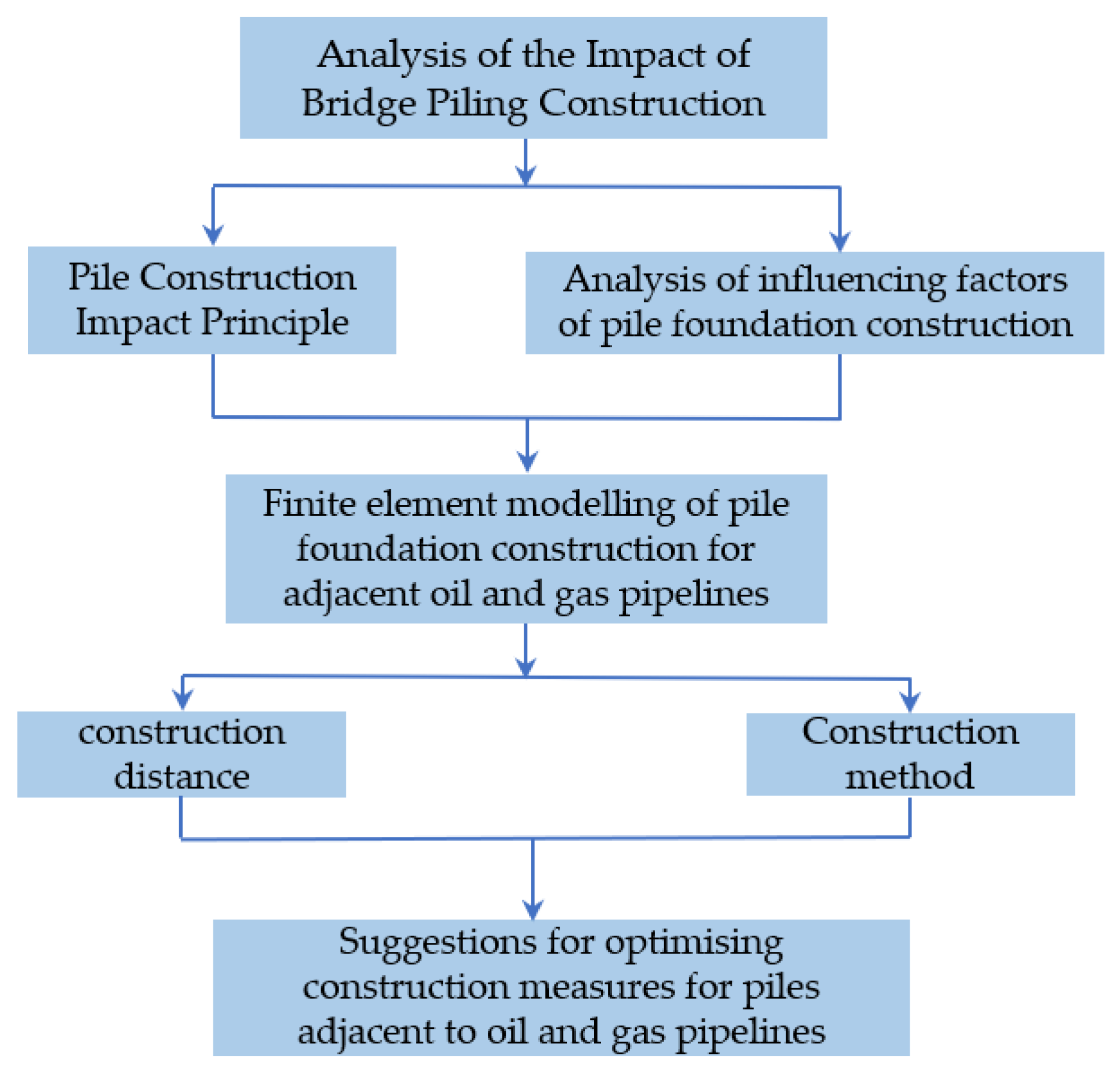
:1. Introduction
2. Materials and Methods
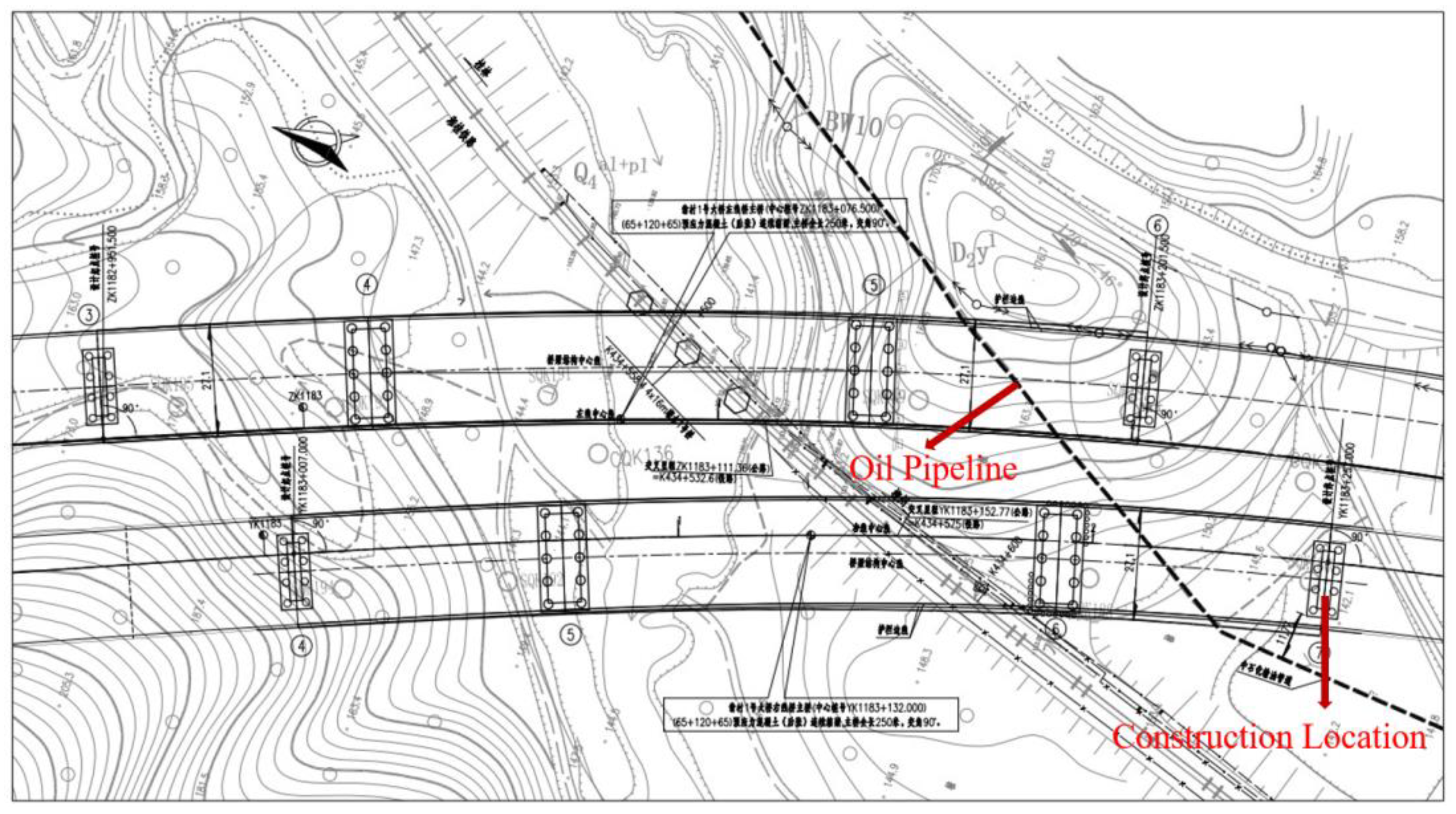
2.1. Project Overview
2.2. Theoretical Analysis of the Role of Pile Excavation on the Influence of Pipelines
2.2.1. Soil Deformation Outside the Pile Excavation Hole and Influencing Factors
2.2.2. Deformation and Damage Mechanism of the Pipeline
2.2.3. Oil Pipeline Safety Control Standards
3. Numerical Simulations
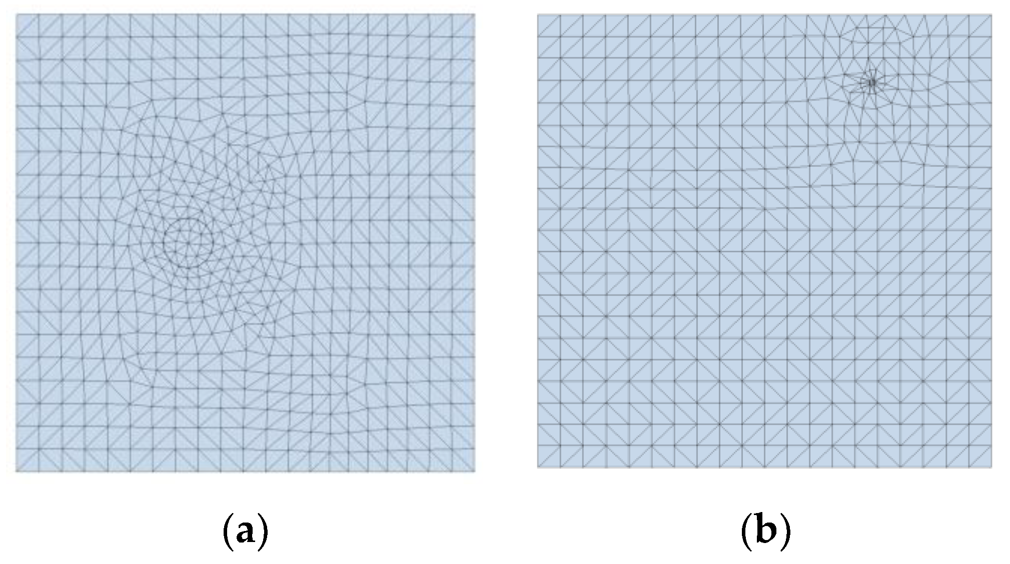
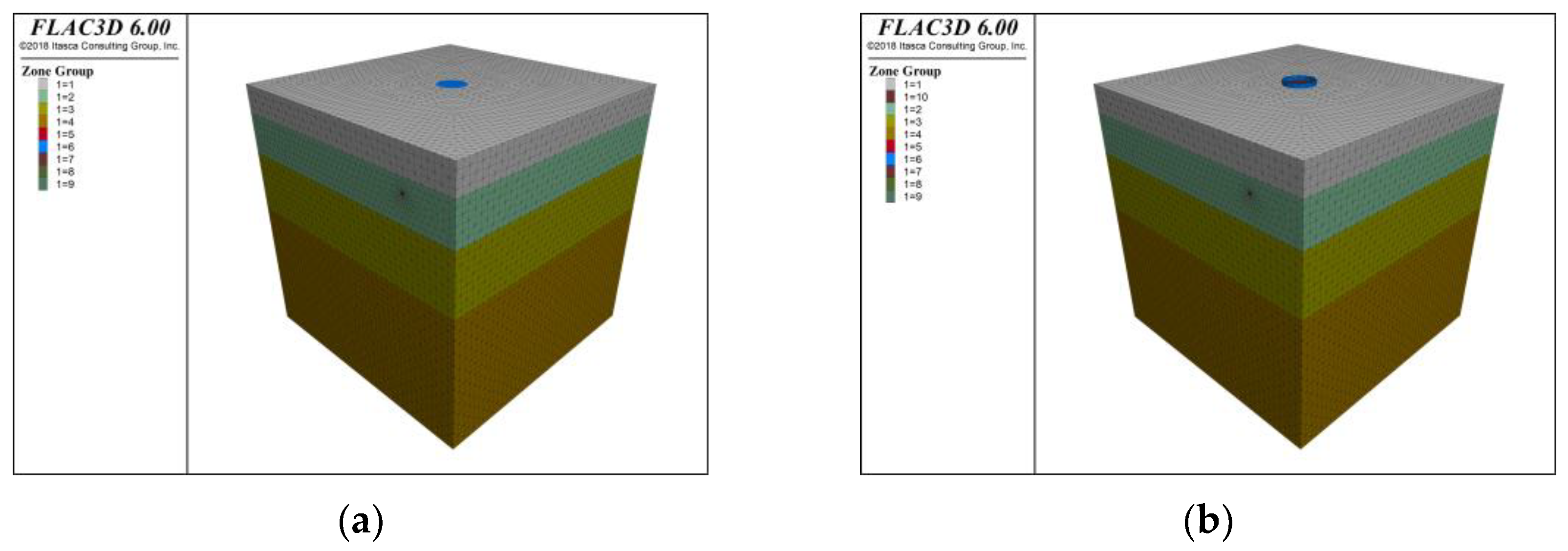
3.1. Model Building
3.2. Model Parameters
3.3. Simulation Scenarios
- The pipelines are considered as equal diameter and equal wall thickness fittings, without considering the effect of the joint fittings, and the constitutive relations are considered as linear elastic materials;
- The soil is considered as a continuous linear elastomer in a porous medium and the Mohr–Coulomb damage criterion is applied (asymmetric solver is chosen);
- There are no contact surface units between the pipeline and the soil, and the two are considered to be in close contact with each other, without misalignment.
4. Results and Discussion
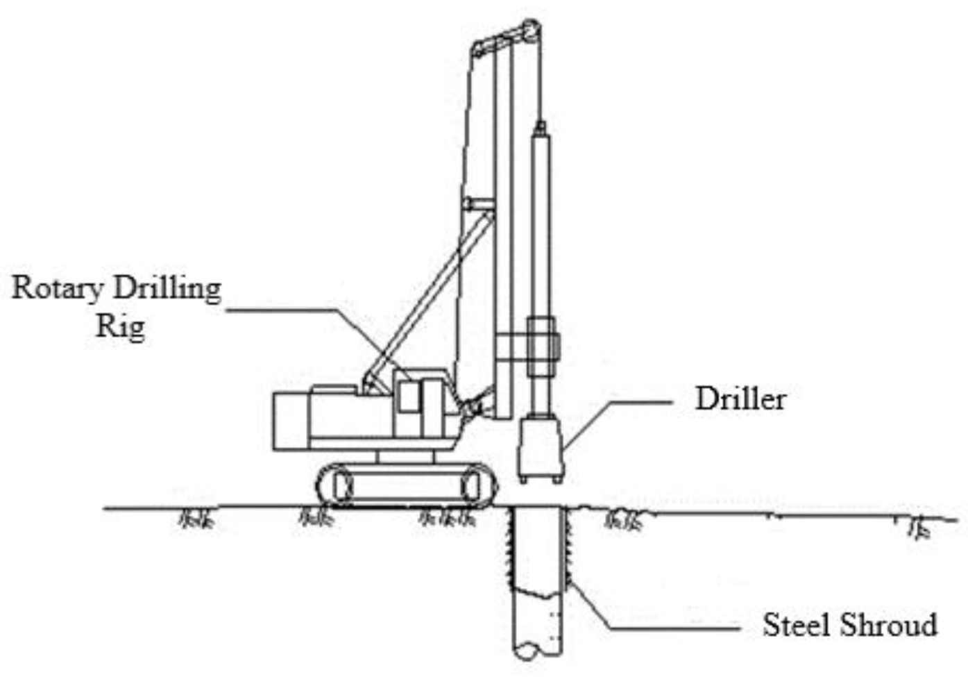
4.1. Simulation of Different Construction Methods
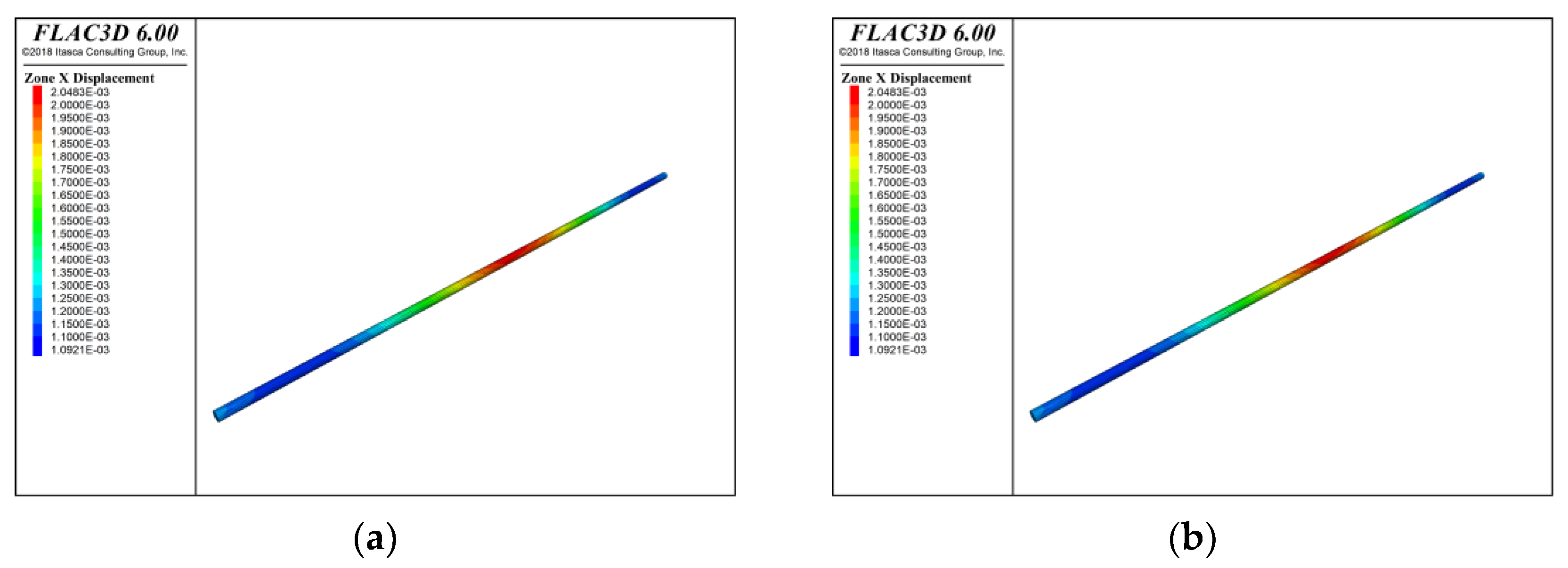
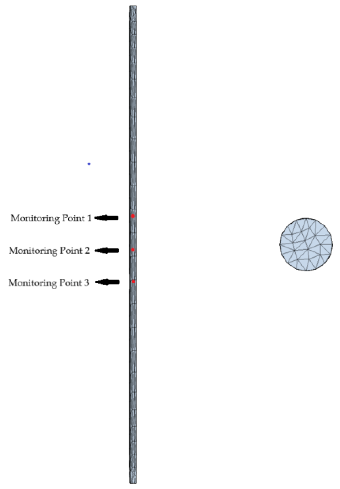
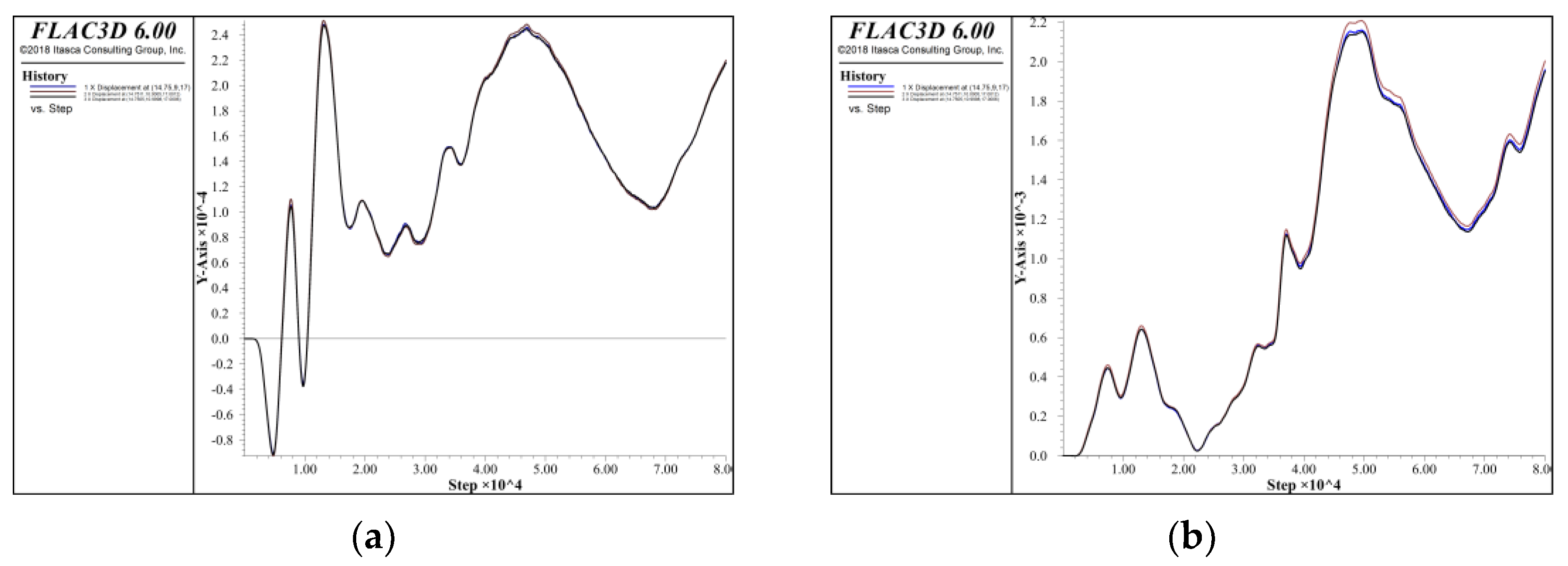
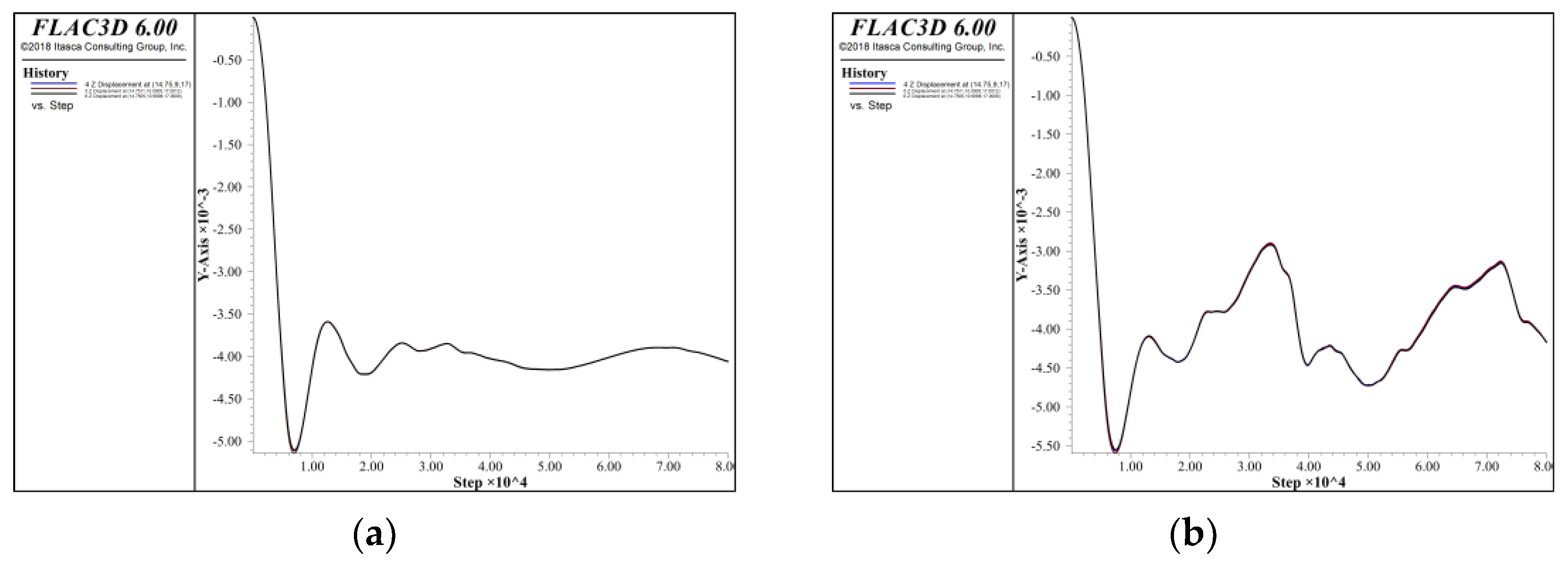
4.1.1. Construction Impact Displacement Analysis
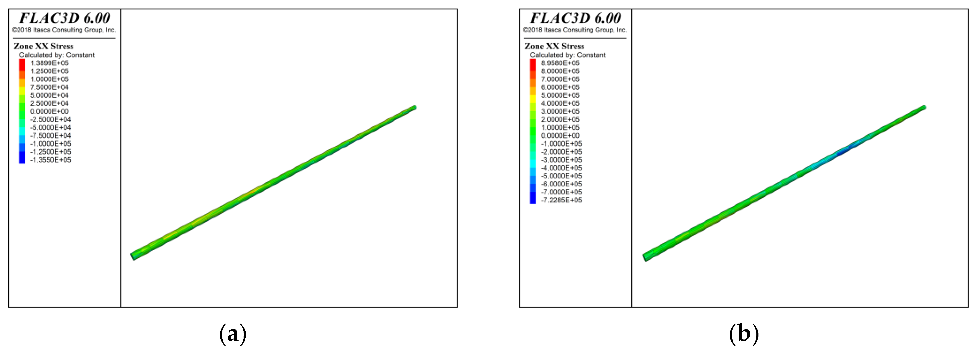
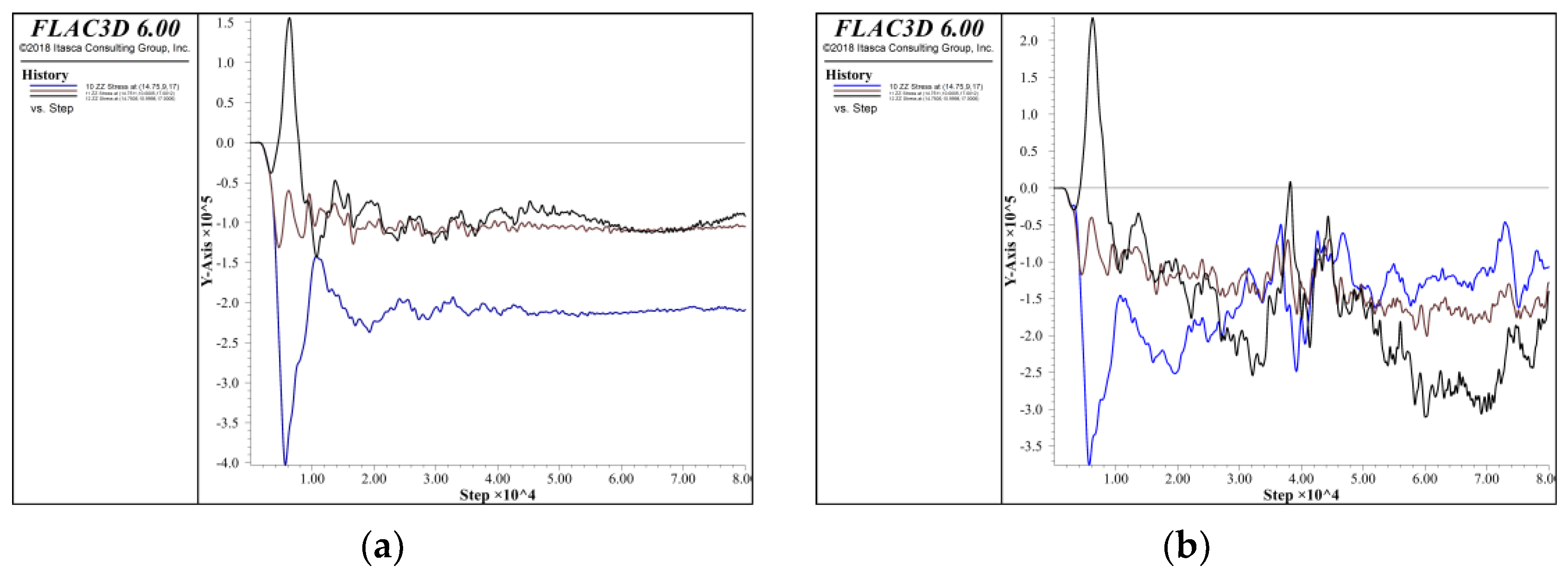
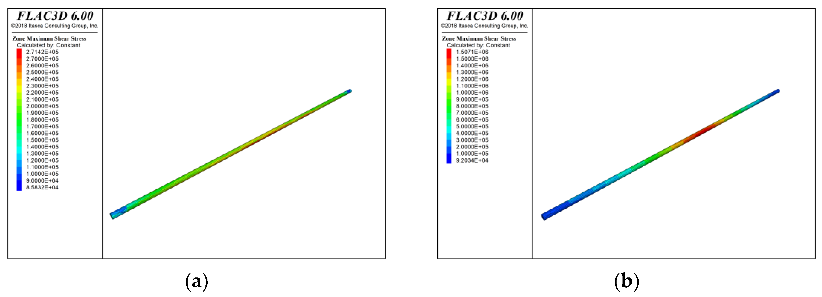
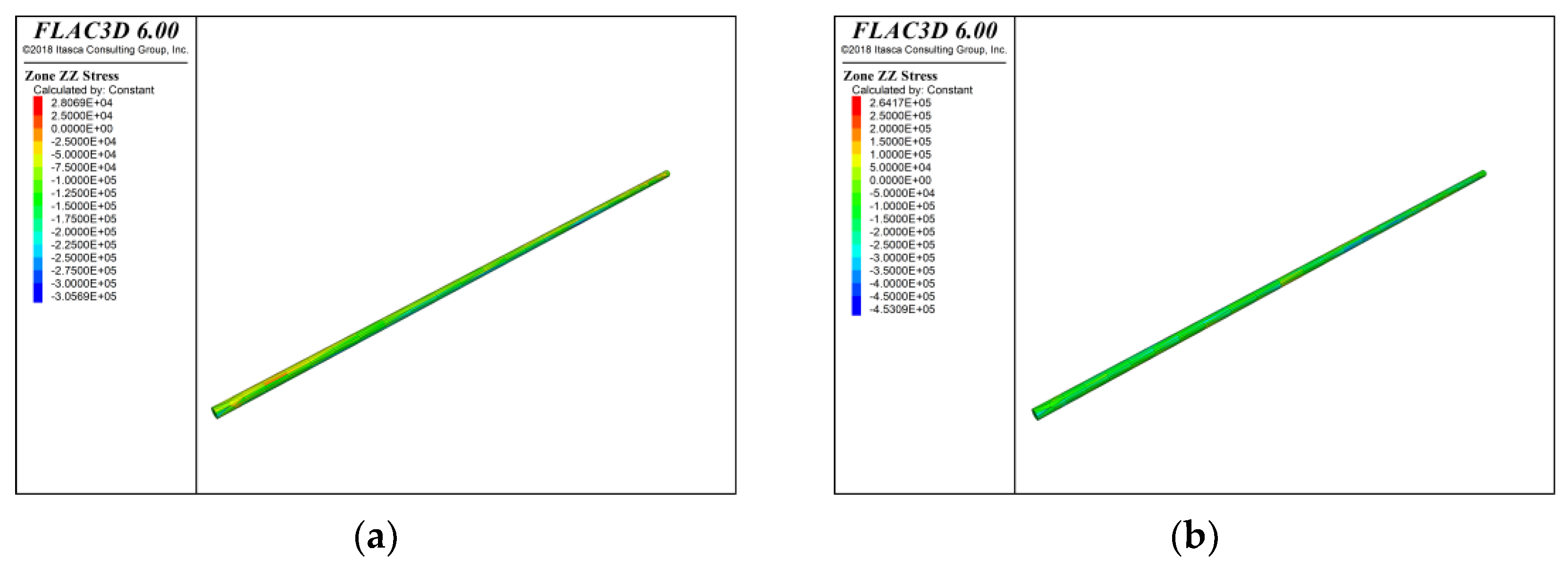
4.1.2. Construction Impact Stress Analysis
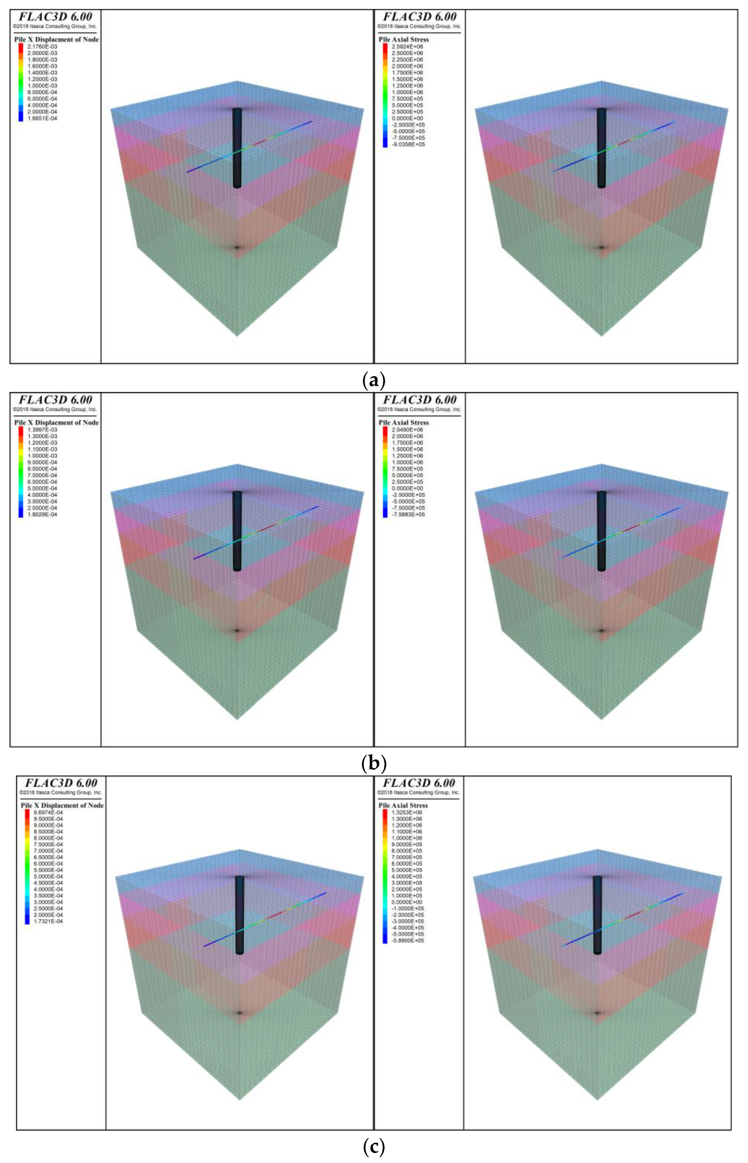
4.2. Simulation of Different Construction Distances
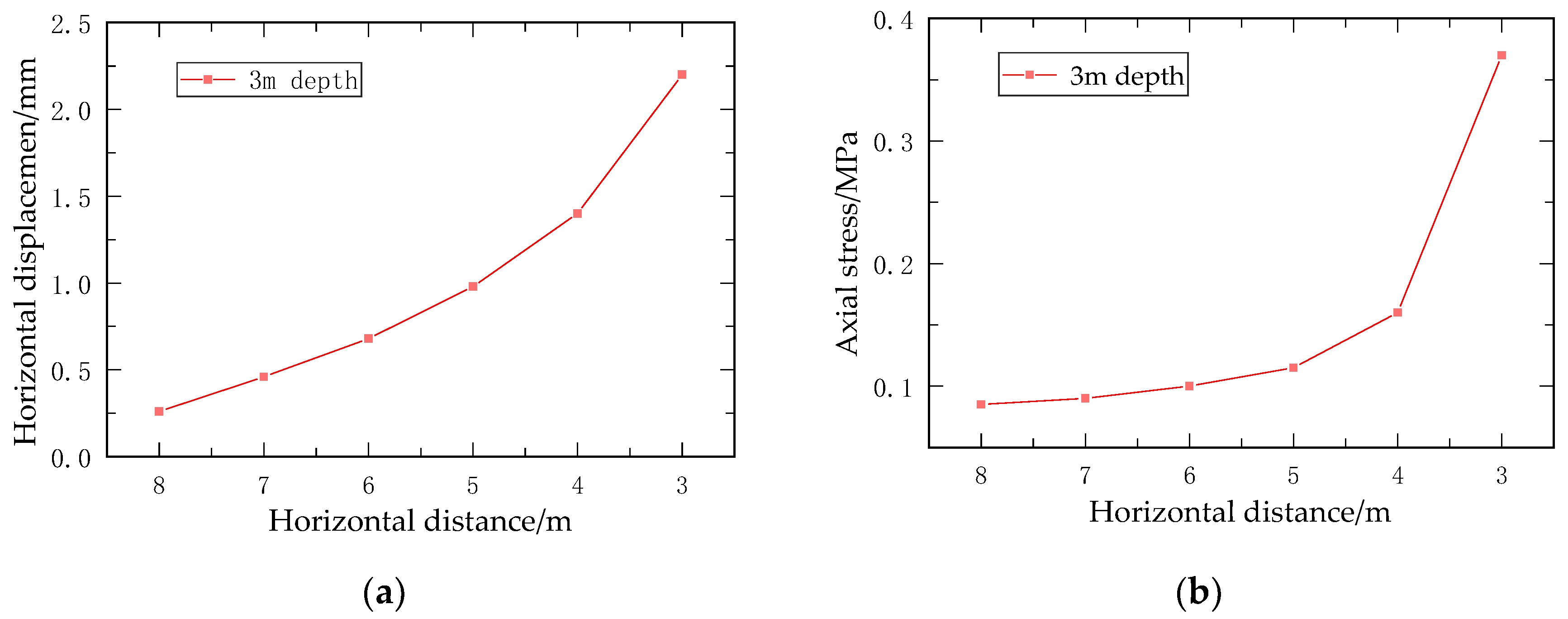
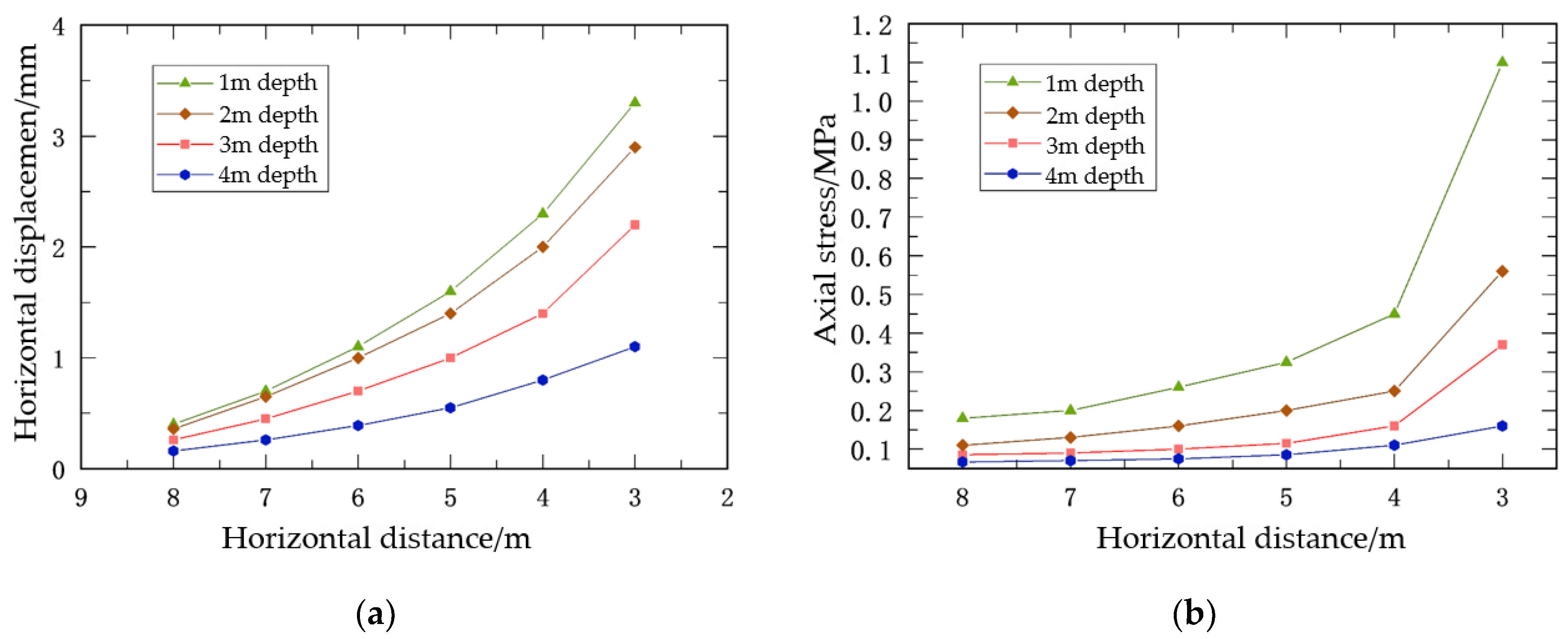
4.2.1. Simulation of Different Horizontal Construction Distances
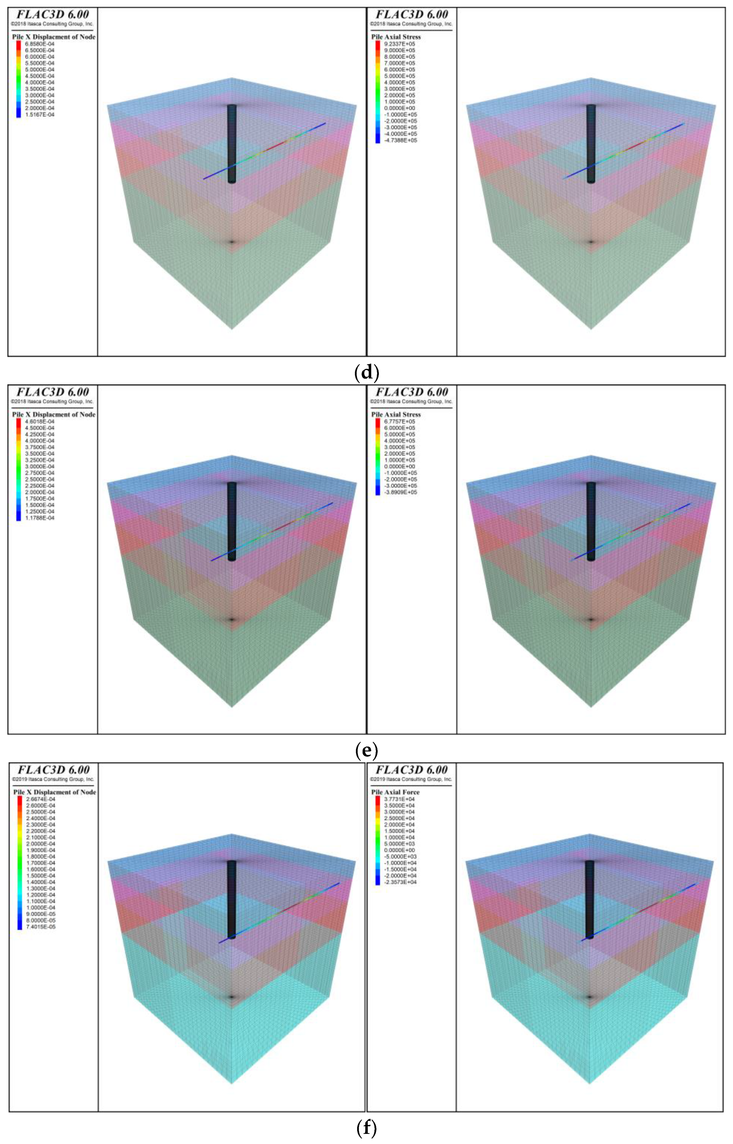
4.2.2. Simulation of Different Burial Depths
5. Conclusions
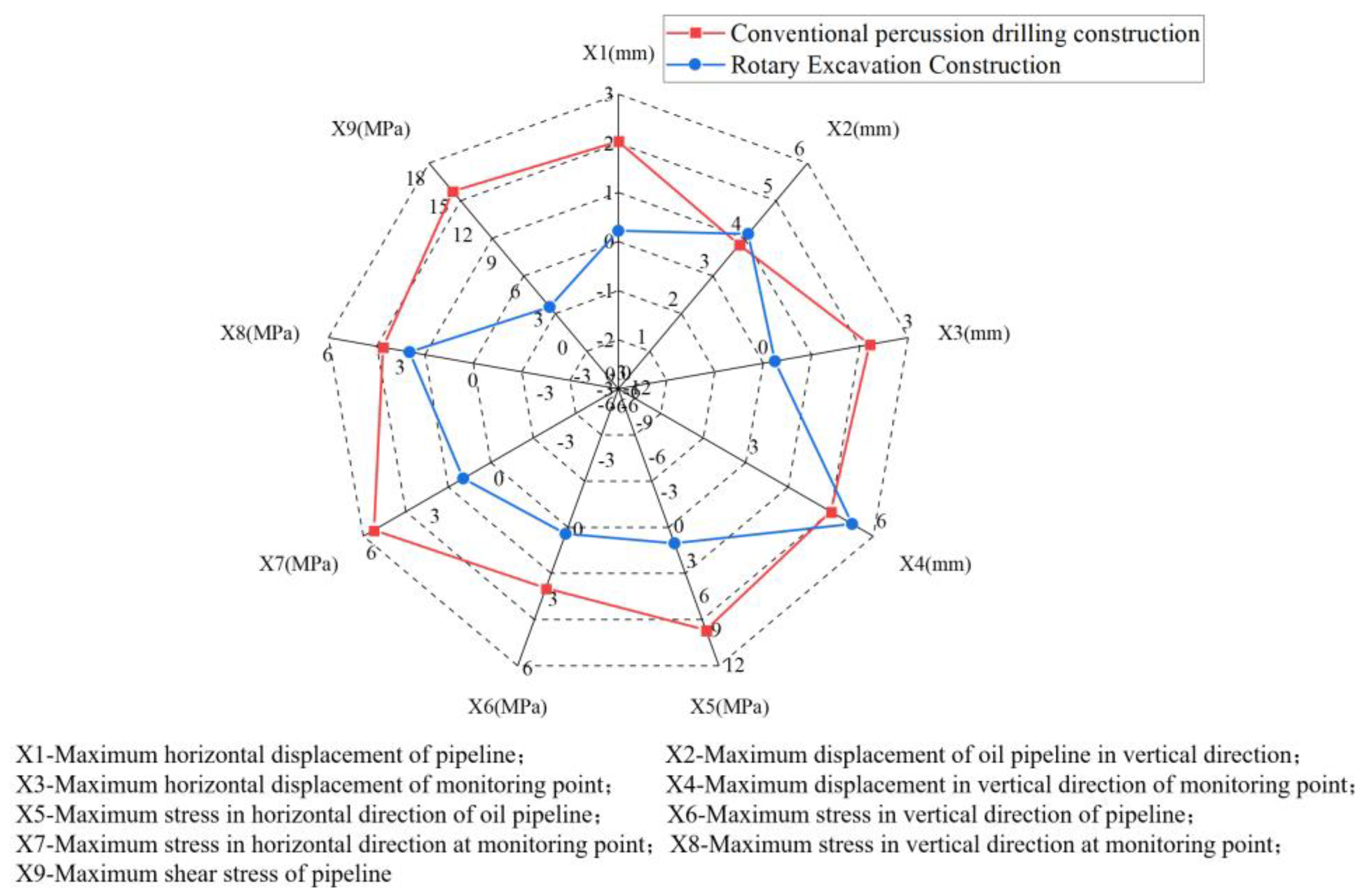
- Compared with traditional impact pile driving construction, the rotary drilling method for pile foundation construction reduced the horizontal displacement of the pipeline by 90%, the vertical displacement by 10%, the horizontal stress on the pipeline by 85% and the vertical stress by 30%;
- During pile foundation construction, both the horizontal displacement and axial stress of the adjacent oil and gas pipelines are negatively correlated with the construction distance. When the construction distance is less than 5 m, if the horizontal distance continues to decrease, the increase in displacement and stress will be much faster than previously. Therefore, it is recommended that the minimum distance between pile foundation construction and oil and gas pipelines should not be less than 5 m;
- An analysis from the perspective of burial depth shows that the pattern of displacement changes does not exhibit significant alterations as the depth decreases. However, a marked increase in the slope of the stress curve can be distinctly observed once the burial depth is reduced to 2 m. Therefore, in practical engineering projects, when encountering pipelines with a burial depth of less than 2 m, greater attention must be paid to the stress impacts caused by construction. It is noteworthy that with a reduction in the burial depth or a decrease in the horizontal construction distance, the phenomenon of stress concentration on the pipelines becomes more pronounced;
- In the case of pile foundation construction near oil pipelines or important buildings, rotary drilling is preferred if environmental conditions permit. This method can effectively minimize the impact on the surrounding environment and structure and ensure construction safety and efficiency.
Author Contributions
Funding
Institutional Review Board Statement
Informed Consent Statement
Data Availability Statement
Acknowledgments
Conflicts of Interest
References
- Li, Q.Y.; Zhao, M.H.; Ren, X.J.; Wang, L.L.; Feng, X.S.; Niu, Y.Q. Construction Status and Development Trend of Chinese Oil & Gas Pipeline. Pipeline Res. Dev. Cent. CNPC 2019, 38, 14–17. [Google Scholar]
- Li, Y.; Li, G.Y.; Ma, W.X. Analysis of The Current Situation and Development Trend of China’s Oil and Gas Pipeline Construction. Sci. Technol. West China 2009, 8, 6–8. [Google Scholar]
- Xin, Y.P. Current Situation and Development Trend of Oil and Gas Pipeline Technology in China. Nat. Gas Oil 2020, 38, 26–31. [Google Scholar]
- Zhang, Y.D.; Qi, A.H. Building A Long-term Mechanism for The Safety and Protection of Oil and Gas Pipelines. Int. Pet. Econ. 2010, 18, 9–16. [Google Scholar]
- Xiao, Z.G. Construction Technology of Percussion Drilling Bored Piles in Bridge Pile Foundation; Sichuan Cement: Chengdu, China, 2021; pp. 127–128. [Google Scholar]
- Alkhdour, A.; Yasin, A.A.; Tiutkin, O. Rational design solutions for deep excavations using soil nail wall systems. Min. Miner. Deposits 2023, 17, 110–118. [Google Scholar] [CrossRef]
- Shirgir, S.; Shamsaddinlou, A.; Zare, R.N.; Zehtabiyan, S.; Bonab, M.H. An efficient double-loop reliability-based optimization with metaheuristic algorithms to design soil nail walls under uncertain condition. Reliab. Eng. Syst. Saf. 2023, 232, 109077. [Google Scholar] [CrossRef]
- Fargier-Galbadon, L.B. Performance of the 8.7-km Bridge Spanning Lake Maracaibo in Venezuela. Pract. Period. Struct. 2020, 25, 05020006. [Google Scholar] [CrossRef]
- Tang, H. Study on Construction Technology of Large Diameter Pouring Pile; South China University of Technology: Guangzhou, China, 2016. [Google Scholar]
- Luo, J.J. Research on the Key Technology of Pile Foundation Construction under Complicated Geologic Conditions of Highway Reconstruction Project Wuxian; Wuhan Institute of Technology: Wuhan, China, 2015. [Google Scholar]
- Poulos, H.G. Pile behavior—Consequences of geological and construction imperfections. J. Geotech. Geoenviron. 2005, 131, 538–563. [Google Scholar] [CrossRef]
- Chang, M.F.; Zhu, H. Construction effect on load transfer along bored piles. J. Geotech. Geoenviron. 2004, 130, 426–437. [Google Scholar] [CrossRef]
- Yao, Z.W. The Stability of the Slurry Hole-Wall of Bored Piles in Thick Sand; Wuhan University of Technology: Wuhan, China, 2012. [Google Scholar]
- Xu, F.Q.; Wang, X. Research on Stability of Hole Wall of Deep Bore-hole with Mud Dado and Limit Deepness of Bore-hole. Master’s Thesis, Lanzhou Jiaotong University, Lanzhou, China, September 2004. [Google Scholar]
- Wang, P.Y.; Tian, M.Z. Discussion on the Problems Arising in the Process of Mechanical Hole Pile Construction in Deep Backfill Strong Karst Field Area. In Proceedings of the Guizhou Rock Mechanics and Engineering Society 2014 Annual Academic Conference, Zunyi, China, 24 October 2014; p. 5. [Google Scholar]
- Pan, X.Y.; Liu, Y.F.; Liu, H. Technology of Preventing Steel Reinforcement Cage Up-floating in Bored Piles Construction. Constr. Technol. 2015, 44, 41–44. [Google Scholar]
- Qing, Q. Research on Construction Disturbance and Control Technology of Shallow Buried Tunnel under Existing Sensitive Buildings. Master’s Thesis, Central South University, Changsha, China, May 2022. [Google Scholar]
- Li, B. Numerical Investigation on Behavior Ofpile Foundation Nearby Shield Tunnelling in Shen Zhen Long Gang Line. Master’s Thesis, Shanghai Jiao Tong University, Shanghai, China, December 2022. [Google Scholar]
- SY 6186-2007; Oil and gas pipeline safety regulations. Petroleum Industry Safety Professional Standardization Technical Committee: Beijing, China, 2008.
- GA 1166-2014; Public security risk levels and security requirements for oil & gas pipeline systems. National Technical Committee for Standardization of Security Alarm Systems: Beijing, China, 2015.
- Zou, L.; Huang, K.; Wang, L.; Butterworth, J.; Ma, X. Vibration control of adjacent buildings considering pile-soil-structure interaction. J. Vib. Control 2012, 18, 684–695. [Google Scholar] [CrossRef]
- Wu, K.; Ye, Z. The Numerical Research on Rock Breaking and Rising Mechanism of Rotary-Percussive Drilling. Arab. J. Sci. Eng. 2019, 44, 10561–10580. [Google Scholar] [CrossRef]
- Xing, H.; Liu, L.; Luo, Y. Effects of Construction Technology on Bearing Behaviors of Rock-Socketed Bored Piles as Bridge Foundations. J. Bridg. Eng. 2019, 24, 05019002. [Google Scholar] [CrossRef]
- Lucifora, D.J. Comparative Modeling, Simulation, and Control of Rotary Blasthole Drills for Surface Mining; Queen’s University: Kingston, ON, Canada, 2012. [Google Scholar]
- Liu, L. Discussion on the application of rotary drilling technology in the pile foundation construction of special bridge. Technol. Innov. Appl. 2023, 13, 193–196. [Google Scholar] [CrossRef]
- Zhou, J.R.; Zhou, N. Application of rotary drilling hole forming technology in bridge pile foundation construction. Constr. Mach. 2022, 45–48. [Google Scholar] [CrossRef]
- Dol, S.S.; Wong, S.F.; Wee, S.K.; Lim, J.S. Experimental Study on the Effects of Water-in-oil Emulsions to Wall Shear Stress in the Pipeline Flow. J. Appl. Fluid Mech. 2018, 11, 1309–1319. [Google Scholar]
- Ignatik, A.A. Stress-strain state of a pipeline subject to the influence of a combined load. Nauka Tehnol. Trubopr. 2020, 10, 22–31. [Google Scholar] [CrossRef]
- Kim, D.; Jeong, S.; Jung, G.; Park, J. Load-sharing ratio of prebored and precast pile in top-down method construction process. Struct. Des. Tall Spec. 2018, 27, 22–31. [Google Scholar] [CrossRef]
- Yang, Y.; Liao, H.; Xu, Y.; Yang, S.; Niu, J. Coupled fluid-structure simulation of a vibration-assisted rotary percussion drilling tool. Energ. Source Part A 2019, 41, 1725–1738. [Google Scholar] [CrossRef]
- Scaccabarozzi, D.; Saggin, B. Measurement of Stress Waves Propagation in Percussive Drilling. Sensors 2021, 21, 3677. [Google Scholar] [CrossRef] [PubMed]


| Piers | Root Number | Φ1.8 m Single Pile Length (m) | Root Number | Φ2.2 m Single Pile Length (m) | |
|---|---|---|---|---|---|
| Left lane of Wengcun No. 1 Bridge | 3# | 8 | 24 | ||
| 4# | 10 | 39 | |||
| 5# | 10 | 46 | |||
| 6# | 8 | 24 | |||
| Right lane of Wengcun No. 1 Bridge | 4# | 8 | 33 | ||
| 5# | 10 | 39 | |||
| 6# | 10 | 39 | |||
| 7# | 8 | 20 | |||
| Total | 32 | 40 | |||
| Piers | HRB400 Steel Reinforcing Bar | HPB300 Steel Reinforcing Bar | C30 Concrete | Φ57 × 3 mm Sonotube | |||
|---|---|---|---|---|---|---|---|
| Φ28 (kg) | Φ25 (kg) | Φ16 (kg) | Φ10 (kg) | (m3) | (m) | ||
| Left lane of Wengcun No. 1 Bridge | 3# | 26,852.65 | 1892.15 | 254.7 | 4587.2 | 492 | 800 |
| 4# | 65,464.7 | 4909.6 | 530.9 | 10,482 | 1488.2 | 1600 | |
| 5# | 76,090.7 | 5646 | 610.5 | 11,872.8 | 1754.3 | 1880 | |
| 6# | 26,852.65 | 1892.15 | 254.7 | 4587.2 | 492 | 800 | |
| Right lane of Wengcun No. 1 Bridge | 4# | 36,589.9 | 2680.6 | 361 | 5738.6 | 674.9 | 1088 |
| 5# | 130,929.3 | 9819.2 | 1061.8 | 20,964.1 | 2976.4 | 3200 | |
| 6# | 130,929.3 | 9819.2 | 1061.8 | 20,964.1 | 2976.4 | 3200 | |
| 7# | 22,679.5 | 1576.8 | 212.4 | 4075.5 | 410.2 | 672 | |
| Total | 516,388.7 | 38,235.7 | 4347.8 | 83,271.5 | 11,264.4 | 13,240 | |
| Stratigraphic Name | Natural Density (kN/m3) | Modulus of Elasticity (MPa) | Poisson’s Ratio | Cohesion (kPa) | Angle of Internal Friction (°) |
|---|---|---|---|---|---|
| Grit | 18 | 6 | 0.49 | 10 | 20 |
| Silty clay | 17 | 30 | 0.48 | 20 | 14 |
| Crushed or broken rock | 18 | 86 | 0.47 | 15 | 24 |
| A block of stone | 20 | 100 | 0.47 | 20 | 30 |
| Strongly weathered Muddy sandstone | 24 | 80 | 0.35 | 18 | 22 |
| Moderately weathered Muddy sandstone | 24 | 120 | 0.35 | 30 | 25 |
| Pipe | 25 | 20,000 | 0.2 |
Disclaimer/Publisher’s Note: The statements, opinions and data contained in all publications are solely those of the individual author(s) and contributor(s) and not of MDPI and/or the editor(s). MDPI and/or the editor(s) disclaim responsibility for any injury to people or property resulting from any ideas, methods, instructions or products referred to in the content. |
© 2024 by the authors. Licensee MDPI, Basel, Switzerland. This article is an open access article distributed under the terms and conditions of the Creative Commons Attribution (CC BY) license (https://creativecommons.org/licenses/by/4.0/).
Share and Cite
Liu, D.; Zhang, X.; Tang, Y.; Jin, Y.; Cao, K. Study on the Impact of Different Pile Foundation Construction Methods on Neighboring Oil and Gas Pipelines under Very Small Clearances. Appl. Sci. 2024, 14, 3609. https://doi.org/10.3390/app14093609
Liu D, Zhang X, Tang Y, Jin Y, Cao K. Study on the Impact of Different Pile Foundation Construction Methods on Neighboring Oil and Gas Pipelines under Very Small Clearances. Applied Sciences. 2024; 14(9):3609. https://doi.org/10.3390/app14093609
Chicago/Turabian StyleLiu, Dunwen, Xiaotian Zhang, Yu Tang, Yuhui Jin, and Kunpeng Cao. 2024. "Study on the Impact of Different Pile Foundation Construction Methods on Neighboring Oil and Gas Pipelines under Very Small Clearances" Applied Sciences 14, no. 9: 3609. https://doi.org/10.3390/app14093609