Article

A Novel Piezoelectric Energy Harvester Using the Macro Fiber Composite Cantilever with a Bicylinder in Water

1
School of Mechatronics Engineering, Harbin Institute of Technology, Harbin 150001, China
2
College of Mechanical and Electrical Engineering, Northeast Forestry University, Harbin 150040, China
*
Author to whom correspondence should be addressed.
Appl. Sci. 2015, 5(4), 1942-1954; https://doi.org/10.3390/app5041942
Submission received: 27 October 2015 / Revised: 8 December 2015 / Accepted: 11 December 2015 / Published: 17 December 2015
(This article belongs to the Special Issue Ferroelectric Ceramics)

Abstract

:
A novel piezoelectric energy harvester equipped with two piezoelectric beams and two cylinders was proposed in this work. The energy harvester can convert the kinetic energy of water into electrical energy by means of vortex-induced vibration (VIV) and wake-induced vibration (WIV). The effects of load resistance, water velocity and cylinder diameter on the performance of the harvester were investigated. It was found that the vibration of the upstream cylinder was VIV which enhanced the energy harvesting capacity of the upstream piezoelectric beam. As for the downstream cylinder, both VIV and the WIV could be obtained. The VIV was found with small L/D, e.g., 2.125, 2.28, 2.5, and 2.8. Additionally, the WIV was stimulated with the increase of L/D (such as 3.25, 4, and 5.5). Due to the WIV, the downstream beam presented better performance in energy harvesting with the increase of water velocity. Furthermore, it revealed that more electrical energy could be obtained by appropriately matching the resistance and the diameter of the cylinder. With optimal resistance (170 kΩ) and diameter of the cylinder (30 mm), the maximum output power of 21.86 μW (sum of both piezoelectric beams) was obtained at a water velocity of 0.31 m/s.

Graphical Abstract

1. Introduction

Energy harvesting from ambient vibration is considered a promising renewable approach for generating electricity. Different transduction mechanisms have been presented, including electrostatic [1], electromagnetic [2,3,4,5], and piezoelectric [6,7,8,9] transduction. The latter transduction theory has received the most attention. Simultaneously, flow-induced vibration exists widely in nature and contains vast amounts of energy, such as flapping waterweeds in flowing water, swing kelp in the ebb or flow of tides, and undulation of pipes and cables in oceans. When the piezoelectric harvester is placed into flowing water, the vortices shed from the harvester, and then reactivate the harvester, making it vibrate. Due to the piezoelectric effect, the piezoelectric harvester is supposed to convert the vibration energy into electricity.
Taylor et al. [10] first presented an eel-shaped piezoelectric energy harvester with five side-by-side flexible beams, which vibrated mechanically in the vortex street. A 10 μW output power was achieved at a water velocity of 1 m/s. Subsequently, many researchers focused on piezoelectric energy harvesting utilizing flow-induced vibration. The flow-induced vibration includes flutter-induced vibration (FIV) [11,12,13,14] and vortex-induced vibration (VIV) [15,16,17]. As for the FIV, Shan et al. [18] investigated a macro fiber composite piezoelectric energy harvester in the water vortex, and 1.32 μW power was generated at a water velocity of 0.5 m/s. Weinstein et al. [19] studied a piezoelectric beam induced by the vortex shedding from an upstream cylinder, and 200 μW and 3 mW of power were respectively generated at air velocities of 3 m/s and 5 m/s. Akaydin et al. [20,21] studied a thin polyvinylidene difluoride cantilever beam, and the maximum output power was obtained when the natural frequency of the energy harvester was equal to the vortex shedding frequency. Under the airflow flutter excitation, the airfoil-based piezoelectric energy harvesters were mathematically and experimentally investigated, and it was pointed out that the airfoil-based energy harvester should be an effective way of converting wind energy into electricity [22,23,24,25,26,27]. Furthermore, with different cross-section geometries (including square, D-shaped, and triangular sections), some galloping-based piezoelectric energy harvesters were presented to increase the output power [28,29,30,31,32,33,34].
Stimulated by the VIV, some vortex-induced piezoelectric energy harvesters were studied and reported [35,36,37,38]. Zhang et al. [39] numerically studied a vortex-induced piezoelectric energy harvester which consisted of a cylinder and two piezoelectric beams. The numerical results showed that more power was obtained with a larger cylinder diameter. Xie et al. [40] studied a pipeline-shaped vortex-induced piezoelectric energy harvester, and 1 mW was generated at an air velocity of 5 m/s when the cylinder was 40 cm in length and 1 cm in diameter. Dai et al. [41] numerically investigated a piezoelectric energy harvester stimulated by means of both VIV and based excitations, and it was found that more power was obtained compared with the VIV alone.
Generally, more energy harvesters generate more power. However, the dynamic response of vortex-induced piezoelectric energy harvesting systems with more cylinders would be complex because of the interacting effects. Taking two cylinders as an example, Abdelkefi et al. [42] studied two vertical piezoelectric energy harvesters arranged in a tandem pattern in the airflow. Both of the harvesters were individually equipped with a circular cylinder and a square section cylinder. It was found that the response of the harvester in the downstream was significantly affected by wake effects of the upstream harvester. This was also apparent in two square-section cylinder piezoelectric harvesters arranged in a tandem pattern. The wake effects increased the dynamic response and energy harvesting performance of the harvester, especially at relatively high flow velocity [43]. Vortex shedding from the upstream cylinder merges into the downstream cylinder and enhances the dynamic response of the downstream cylinder, which is called wake-induced vibration (WIV). Therefore, the WIV increases the energy harvesting performance of the harvester compared with the single cylinder harvester. Inspired by the wake effects of two cylinders, in this paper, we proposed a novel energy harvester with two piezoelectric beams and two cylinders in water. The energy harvesting performance of this harvester was measured in a home-built testing platform. The effects of resistance, cylinder diameter and water velocity on energy harvesting performance were studied.

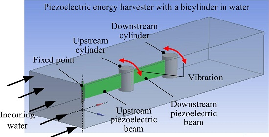
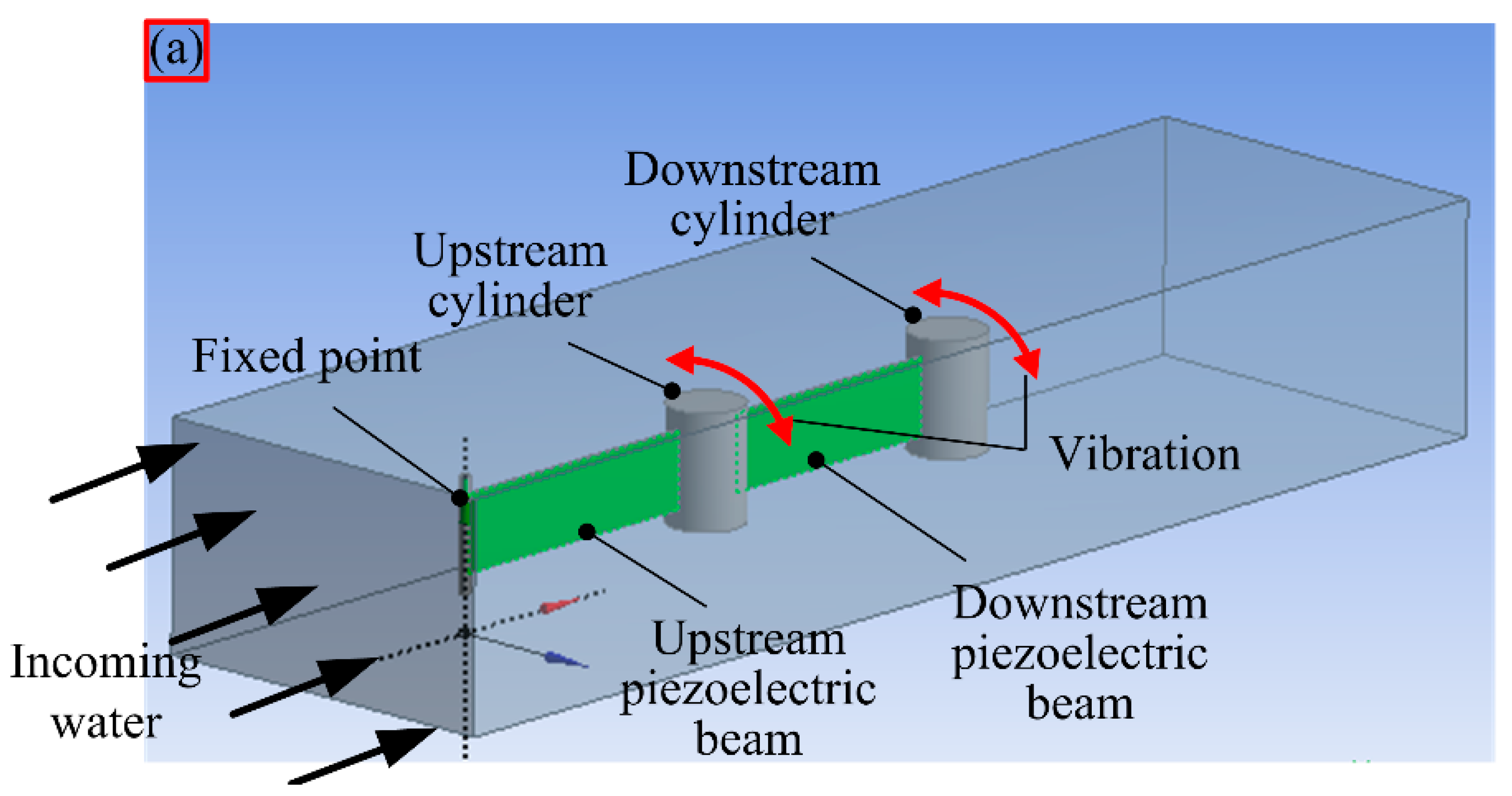
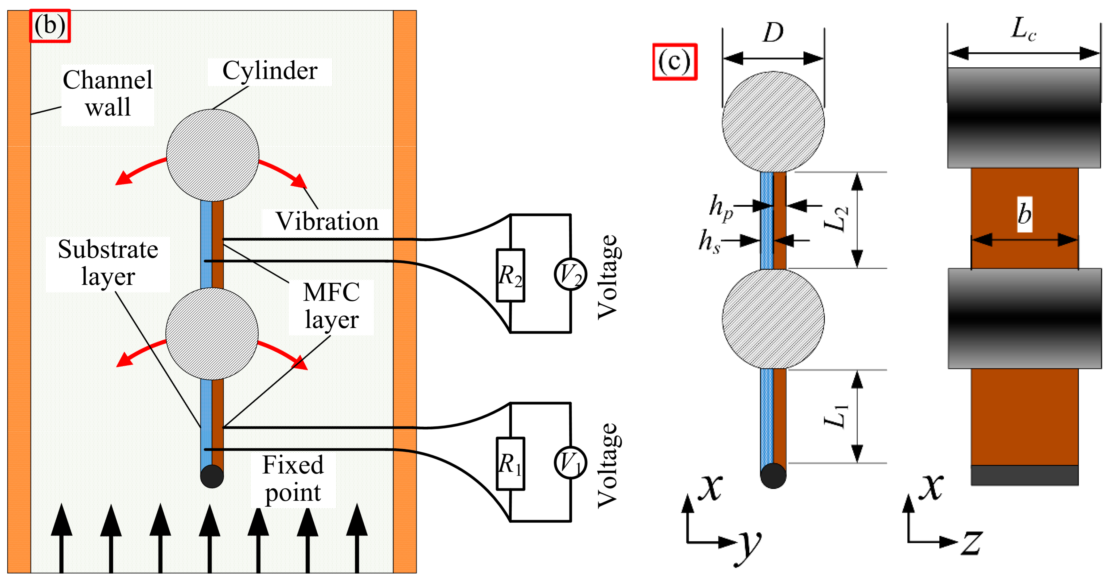
2. Physics Statement

Figure 1 shows a physical model of the energy harvesting system. The energy harvesting system is composed of a water channel and a piezoelectric energy harvester. The energy harvester is fixed in the upstream and consists of two piezoelectric beams and two cylinders. The cylinders are equipped at the end of the piezoelectric beams. The downstream piezoelectric beam is connected to the upstream cylinder. As to the piezoelectric beam, a waterproof piezoelectric layer, a macro fiber composite (MFC) (Smart Material Corporation®, Dresden, Germany), is attached to the substrate layer. Piezoelectric beams are identical in both material properties and structure. The thicknesses of the substrate layer and the piezoelectric layer are hs = 0.1 mm and hp = 0.3 mm. The active lengths of both piezoelectric beams are L1 = 30 mm and L2 = 30 mm, respectively. The resistances R1 and R2 are individually attached to the upstream and downstream piezoelectric beams. The output voltages V1 and V2 can be obtained across the R1 and R2, as shown in Figure 1b. The length of the cylinder is Lc =20 mm and the width of the piezoelectric beam is b =16 mm. D is the diameter of the cylinder, as shown in Figure 1c.
Figure 1. Schematic of the piezoelectric energy harvesting system: (a) system diagram; (b) schematic diagram; (c) dimensional diagram.
Applsci 05 01942 g001aApplsci 05 01942 g001b

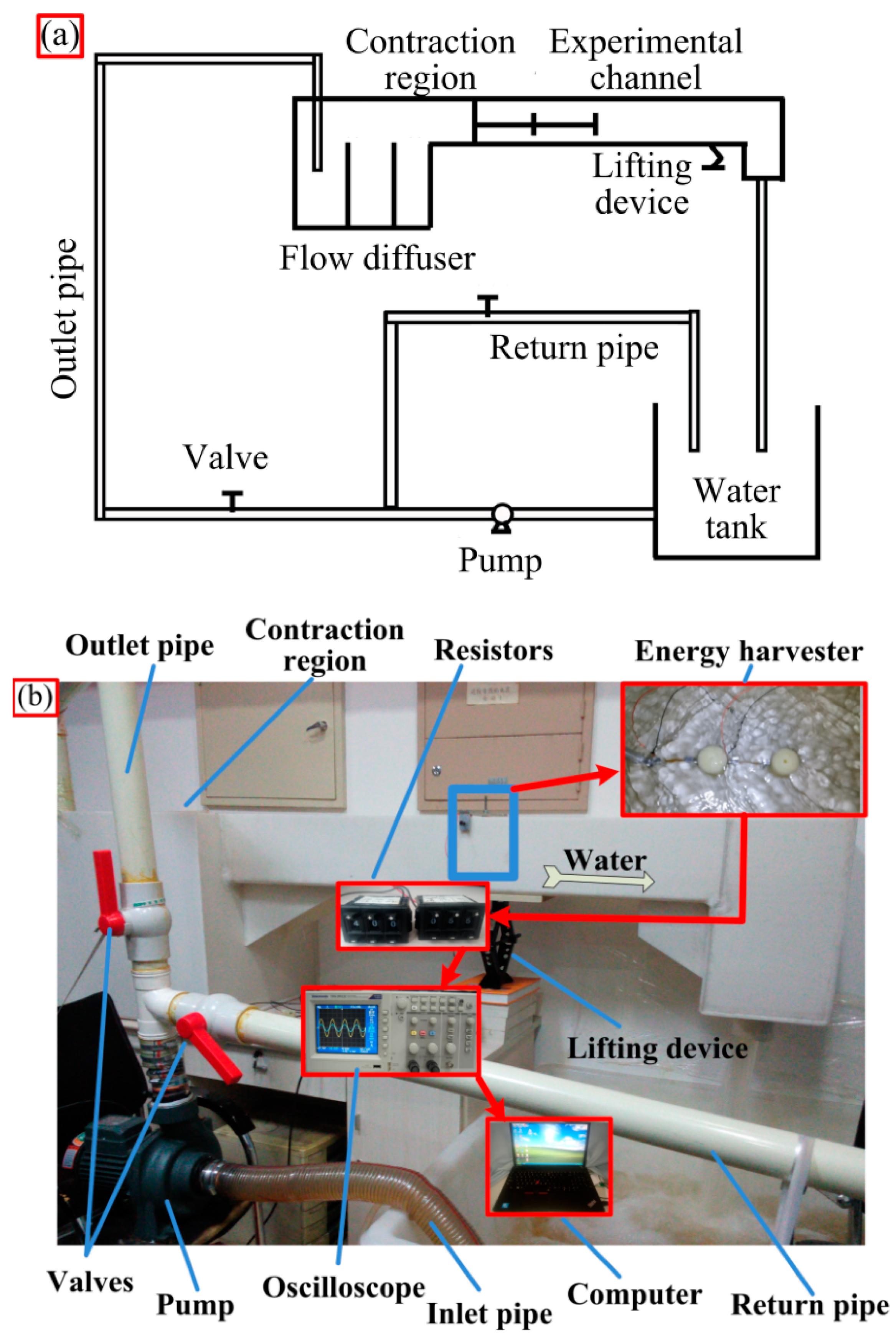
3. Experimental Section

Figure 2a illustrates the schematic diagram of the experimental platform. Water is pumped into the experimental channel from a tank through pipes utilizing a pump. The water flow is controlled by two valves. The superfluous water flows back into the tank through a return pipe. The gradient of the experimental channel is adjusted by a lifting device. The water velocity is effectively controlled by adjusting both the water flow and the gradient of the experimental channel. The laminar flow is produced by a flow diffuser (Qingdao Tonglide Plastic Honeycomb Co., Ltd®, Qingdao, China) in the contraction region, as shown in Figure 2a. In order to reduce the disturbances caused by the channel walls and the air on the flowing water, the piezoelectric energy harvester was fully immersed into the incoming water and placed in the middle of the experimental channel. The output voltages were obtained when the water current flowed across the harvester. The data of output voltages were measured and stored using an oscilloscope, which were finally analyzed using a computer, as shown in Figure 2b.
Figure 3 shows the experimental prototype of the piezoelectric energy harvester which consists of two cylinders, four fixtures, two piezoelectric beams and a streamlined fixed end. The materials of both cylinders and fixtures were polyamide and aluminum, respectively. The fixtures and fixed end were designed to be thin slices to reduce the disturbances to the laminar flow. The piezoelectric beam was composed of a MFC layer (M2814-P2) and a polyvinyl chloride (PVC) layer (Shenzhen Guanye Electronic Material Co., Ltd®, Shenzhen, China). Electric wires were connected to the terminal of two MFC layers, on which the silica gel was covered to insulate water. To ensure the waterproofness of the whole piezoelectric energy harvester, a plastic foil was used to cover the piezoelectric beams completely. The spacing distance between the two cylinders is L = Ls + D, where Ls is a constant value (45 mm), as shown in Figure 3. Table 1 lists the detailed material parameters of the energy harvester prototype.
Figure 2. Schematic diagram of the experimental set-up and a picture of the experimental platform: (a) schematic diagram of the experimental set-up; (b) experimental platform.
Applsci 05 01942 g002
Figure 3. Experimental prototype of the piezoelectric energy harvester.
Applsci 05 01942 g003
Table 1. Material properties of the piezoelectric energy harvester.
ParametersValues
Piezoelectric layer density, ρp (kg/m3)5540
Substrate layer density, ρs (kg/m3)1400
Fluid density, ρf (kg/m3)1000
Young modulus of the piezoelectric layer, Ep (GPa)15.857
Young modulus of the elastic beam, Es (GPa)3.5
Piezoelectric constant, d31 (pC/N)−210
Capacitance, Cp (nF)30.78
Active width of the piezoelectric layer, b (mm)14
Cylinder density, ρc (kg/m3)1150

4. Results and Discussion

The output power is one of the most significant indexes for the piezoelectric energy harvester, which mainly depends on the external resistance, the structural dimensions and the water velocity here. Firstly, the effects of external resistances on the output power were investigated. Figure 4 illustrates the variation of output power of the two piezoelectric beams with different load resistances, which the velocities of the water maintained at 0.25 m/s, 0.31 m/s, and 0.36 m/s. Also, the diameter of the cylinders is 30 mm here. It can be found that the output power initially increases with the increase of the resistance until reaching the peak output power, and then decreases while the resistance continues to increase. The optimal resistance corresponds to the peak output power. In other words, the maximum output power can be generated with a specific resistance. The optimal resistances of both piezoelectric beams are 190 kΩ, 170 kΩ, and 150 kΩ when the velocities are 0.25 m/s, 0.31 m/s, and 0.36 m/s, respectively, as shown in Figure 4a,b.
The optimal resistance R can be theoretically expressed as
R = 1 2 π f C p
where, f is the vortex shedding frequency
f = S t U D
where, St is the Strouhal number, and U is the velocity of water flow. Hence, we can obtain the relationship R 1/U, R D. The optimal resistance R decreases with increasing velocity U. However, the optimal resistance R increases when the diameter of the cylinder D increases. In addition, it can be found that the output power of the upstream beam is larger than that of the downstream beam, as shown in Figure 4.
Figure 4. Relationship between the resistance R and the output power P at velocities of 0.25 m/s, 0.31 m/s, and 0.36 m/s: (a) upstream beam; (b) downstream beam.
Applsci 05 01942 g004
Here, the relationship between the output power of both piezoelectric beams (the upstream and downstream beams) was investigated. The diameter of the cylinder of 30 mm and the resistance of 170 kΩ were set in the following tests. Figure 5a shows the output voltages of each piezoelectric beam versus time at a water velocity of 0.225 m/s. Figure 5b,c is the FFT analysis result of the output voltages of the upstream and downstream beams, respectively. It can be found that the output peak-to-peak voltage Vp-p of the upstream piezoelectric beam is about 3.2 times as high as that of the downstream one. The average power P = V RMS 2 /R of the upstream beam is about 10 times as large as that of the downstream beam. In other words, the upstream piezoelectric beam plays a major role in the energy harvesting performance of the harvester. The reason is that, along with the x direction of water flow, the stress distribution of the piezoelectric beam varies with different bending deflections. Due to the fact that the strain near the fixed point is larger than that of the free end, the upstream piezoelectric beam is prone to producing more power than the downstream beam. Furthermore, it can be found that the vibration frequencies of the two cylinders are both 1.28 Hz, see Figure 5b,c. Also, the Strouhal number St (St = 0.171) can be calculated by Equation (2), which is slightly smaller than the single-cylinder value (St = 0.21). The result of St is in good agreement with the results given by the two cylinders arranged in a tandem pattern (St is about 1.5–1.8) described in References [44,45].
Vortex shedding from the upstream cylinder can affect the energy harvesting performance of the downstream piezoelectric beam, as shown in Section 1 (Introduction). To further investigate the wake effects on the performance of the harvester, we tested the output power of each single piezoelectric beam (the upstream and the downstream) versus the velocity of water with different cylinder diameters, namely, D = 10 mm, 15 mm, 20 mm, 25 mm, 30 mm, 35 mm, and 40 mm. Furthermore, the resistance was also equal to 170 kΩ here. Hence, the ratio of the spacing distance to the diameter of the cylinder (L/D) is 5.5, 4, 3.25, 2.8, 2.5, 2.28, and 2.125, respectively. Figure 6 shows the output power of both piezoelectric beams. For the upstream beam, the output power initially increases until reaching the maximum value, and then decreases with the water velocity increasing. The reason is that the vibration mode of the upstream cylinder is VIV. The output power is small when the velocity is low because both the vibration frequency and the amplitude are relatively small. With the increase of the velocity, the vibration frequency, amplitude and output power increase. When the vortex shedding frequency f is equal to the natural frequency ωs of the energy harvester, the vortex-induced resonance is obtained. Then, the dynamic response is enhanced and the maximum output power can be achieved. From Figure 6a, it can be found that for all diameters, the vortex-induced resonance velocities are all around 0.3 m/s in this experimental study. The reason is that the changes of the cylinder diameter (increase or decrease) synchronously change the vortex shedding frequency f and the natural frequency of the energy harvester ωs (decrease or increase), which makes it easier for the vortex shedding frequency f to reach the natural frequency ωs with little changes in velocity.
Figure 5. Output voltage and its Fast Fourier Transform (FFT) analysis: (a) output voltage of both the upstream and downstream piezoelectric beams as a function of time; (b) FFT analysis of the upstream beam; (c) FFT analysis of the downstream beam.
Applsci 05 01942 g005
Figure 6b shows that when the diameters of the cylinder are 10 mm, 15 mm, and 20 mm, the output power of the downstream beam continuously increases with the increase in velocity. The reason is that wakes from the upstream cylinder continuously enhance the vibration response of the downstream cylinder with the increase of velocity. The vibration mode of the downstream cylinder is WIV for the L/D of 3.25, 4, and 5.5. However, for cylinder diameters of 25 mm, 30 mm, 35 mm, and 40 mm, the output power of the downstream beam initially increases until reaching the maximum value, and then decreases with increasing water velocity. The above results show the same trend with those of the upstream beam. This is because the vibration condition of the downstream cylinder is also VIV when the L/D is small, namely 2.125, 2.28, 2.5, and 2.8. Therefore, it can be summarized that the vibration response of the upstream cylinder is VIV. Meanwhile, both the VIV and WIV modes can be obtained for the downstream cylinder. In this study, the VIV phenomenon predominated when L/D was small (namely 2.125, 2.28, 2.5, and 2.8), while the WIV mode was achieved when the L/D was relatively large, such as 3.25, 4, and 5.5.
In addition, it can be found that the output power increases until it reaches the diameter of 30 mm, and then decreases as the cylinder diameter continues to increase, as shown in Figure 6a,b. The reason is that the vibration response is weak when the cylinder diameter is small. By increasing the cylinder diameter, the fluid force increases. Hence, the vibration response and the output power increase. By continuously increasing the diameter, the mass of the cylinder increases, combined with the added damping and the added mass from the water flow, which eventually reduce the dynamic response of the energy harvester. In addition, the vibration frequency decreases simultaneously. Consequently, the output power decreases when the diameter of the cylinder continuously increases beyond a certain point. Thus, it can be demonstrated that the energy harvesting performance of the harvester can be enhanced by appropriately selecting a cylinder diameter. Finally, the maximum output power of P = 21.86 μW (the sum of the upstream and downstream beams) is obtained when the cylinder diameter is 30 mm and the velocity of water is 0.31 m/s.
Figure 6. Energy harvesting performance versus water velocities with different cylinder diameters: (a) upstream beam; (b) downstream beam.
Applsci 05 01942 g006

5. Conclusions

In this paper, a piezoelectric energy harvester with two piezoelectric beams and two cylinders was proposed. This piezoelectric energy harvester could convert the fluid kinetic energy into electricity utilizing both vortex-induced vibration (VIV) and wake-induced vibration (WIV). The energy harvesting performances of both the upstream and downstream piezoelectric beams were investigated. The experimental results showed that the vibration mode of the upstream cylinder was VIV. The vortex-induced resonance could enhance the energy harvesting performance of the upstream beam. However, the vibration mode of the downstream cylinder varied with the different ratios of the spacing distance to the diameter of the cylinder (L/D). Both the VIV and the WIV modes could be achieved. The VIV mode was also found with a smaller L/D, likely, 2.125, 2.28, 2.5, and 2.8. The WIV mode was achieved when the L/D was large, such as 3.25, 4, and 5.5. Increased output power could be achieved with increased velocity for the WIV mode due to the wake effects of the upstream cylinder.
The output power of the upstream beam was larger than that of the downstream beam because of the stress distributions. Furthermore, the present work revealed that it was an effective method for enhancing performance of piezo-hydroelastic energy harvesters by appropriately matching the resistances and the cylinder diameters. With an optimal resistance (170 kΩ) and an appropriate diameter (30 mm), the maximum output power of the harvester (21.86 μW) was achieved at a water velocity of 0.31 m/s.

Acknowledgments

This work was financially supported by the Fundamental Research Funds for the Central Universities (Grant No. HIT. NSRIF. 2014059 and No. HIT. KISTP. 201412).

Author Contributions

All authors conceived and designed the experiments; Rujun Song set up the experimental platform; Rujun Song and Fengchi Lv conducted the experiments; all authors contributed to analyzing the experimental data and writing the paper; Jinzhe Li contributed to revising the paper.

Conflicts of Interest

The authors declare no conflict of interest.

References

  1. Lallart, M.; Richard, C.; Garbuio, L.; Petit, L.; Guyomar, D. High efficiency, wide load bandwidth piezoelectric energy scavenging by a hybrid nonlinear approach. Sens. Actuators A 2011, 165, 294–302. [Google Scholar] [CrossRef]
  2. Shan, X.; Xu, Z.; Xie, T. New electromechanical coupling model and optimization of an electromagnetic energy harvester. Ferroelectrics 2013, 450, 66–73. [Google Scholar] [CrossRef]
  3. Shan, X.; Xu, Z.; Song, R.; Xie, T. A new mathematical model for a piezoelectric-electromagnetic hybrid energy harvester. Ferroelectrics 2013, 450, 57–65. [Google Scholar] [CrossRef]
  4. Elvin, N.G.; Elvin, A.A. An experimentally validated electromagnetic energy harvester. J. Sound Vib. 2011, 330, 2314–2324. [Google Scholar] [CrossRef]
  5. Glynne-Jones, P.; Tudor, M.J.; Beeby, S.P.; White, N.M. An electromagnetic, vibration-powered generator for intelligent sensor systems. Sens. Actuators A 2004, 110, 344–349. [Google Scholar] [CrossRef]
  6. Erturk, A.; Inman, D.J. An experimentally validated bimorph cantilever model for piezoelectric energy harvesting from base excitations. Smart Mater. Struct. 2009, 18. [Google Scholar] [CrossRef]
  7. Wang, H.; Tang, L.; Shan, X.; Xie, T.; Yang, Y. Modeling and performance evaluation of a piezoelectric energy harvester with segmented electrodes. Smart Struct. Syst. 2014, 14, 247–266. [Google Scholar] [CrossRef]
  8. Yuan, J.; Xie, T.; Chen, W.; Shan, X.; Jiang, S. Performance of a drum transducer for scavenging vibration energy. J. Intell. Mater. Syst. Struct. 2009, 20, 1771–1777. [Google Scholar] [CrossRef]
  9. Yuan, J.; Shan, X.; Xie, T.; Chen, W. Modeling and improvement of a cymbal transducer in energy harvesting. J. Intell. Mater. Syst. Struct. 2010, 21, 765–771. [Google Scholar] [CrossRef]
  10. Taylor, G.W.; Burns, J.R.; Kammann, S.A.; Powers, W.B.; Welsh, T.R. The energy harvesting eel: A small subsurface ocean/river power generator. IEEE J. Ocean. Eng. 2001, 26, 539–547. [Google Scholar] [CrossRef]
  11. Wang, D.-A.; Chiu, C.-Y.; Pham, H.-T. Electromagnetic energy harvesting from vibrations induced by kármán vortex street. Mechatronics 2012, 22, 746–756. [Google Scholar] [CrossRef]
  12. Wang, D.A.; Chao, C.W.; Chen, J.H. A miniature hydro-energy generator based on pressure fluctuation in karman vortex street. J. Intell. Mater. Syst. Struct. 2012, 24, 612–626. [Google Scholar] [CrossRef]
  13. Tam Nguyen, H.-D.; Pham, H.-T.; Wang, D.-A. A miniature pneumatic energy generator using kármán vortex street. J. Wind Eng. Ind. Aerodyn. 2013, 116, 40–48. [Google Scholar] [CrossRef]
  14. McCarthy, J.M.; Watkins, S.; Deivasigamani, A.; John, S.J.; Coman, F. An investigation of fluttering piezoelectric energy harvesters in off-axis and turbulent flows. J. Wind Eng. Ind. Aerodyn. 2015, 136, 101–113. [Google Scholar] [CrossRef]
  15. Raghavan, K.; Bernitsas, M.M. Experimental investigation of reynolds number effect on vortex induced vibration of rigid circular cylinder on elastic supports. Ocean Eng. 2011, 38, 719–731. [Google Scholar] [CrossRef]
  16. Norberg, C. Fluctuating lift on a circular cylinder: Review and new measurements. J. Fluids Struct. 2003, 17, 57–96. [Google Scholar] [CrossRef]
  17. Sarpkaya, T. A critical review of the intrinsic nature of vortex-induced vibrations. J. Fluids Struct. 2004, 19, 389–447. [Google Scholar] [CrossRef]
  18. Shan, X.; Song, R.; Liu, B.; Xie, T. Novel energy harvesting: A macro fiber composite piezoelectric energy harvester in the water vortex. Ceram. Int. 2015, 41, S763–S767. [Google Scholar] [CrossRef]
  19. Weinstein, L.A.; Cacan, M.R.; So, P.M.; Wright, P.K. Vortex shedding induced energy harvesting from piezoelectric materials in heating, ventilation and air conditioning flows. Smart Mater. Struct. 2012, 21. [Google Scholar] [CrossRef]
  20. Akaydin, H.D.; Elvin, N.; Andreopoulos, Y. Energy harvesting from highly unsteady fluid flows using piezoelectric materials. J. Intell. Mater. Syst. Struct. 2010, 21, 1263–1278. [Google Scholar] [CrossRef]
  21. Akaydın, H.D.; Elvin, N.; Andreopoulos, Y. Wake of a cylinder: A paradigm for energy harvesting with piezoelectric materials. Exp. Fluids 2010, 49, 291–304. [Google Scholar] [CrossRef]
  22. Sousa, V.C.; de M Anicézio, M.; de Marqui, C., Jr.; Erturk, A. Enhanced aeroelastic energy harvesting by exploiting combined nonlinearities: Theory and experiment. Smart Mater. Struct. 2011, 20. [Google Scholar] [CrossRef]
  23. Abdelkefi, A.; Nuhait, A.O. Modeling and performance analysis of cambered wing-based piezoaeroelastic energy harvesters. Smart Mater. Struct. 2013, 22. [Google Scholar] [CrossRef]
  24. Abdelkefi, A.; Nayfeh, A.H.; Hajj, M.R. Design of piezoaeroelastic energy harvesters. Nonlinear Dyn. 2011, 68, 519–530. [Google Scholar] [CrossRef]
  25. Abdelkefi, A.; Nayfeh, A.H.; Hajj, M.R. Modeling and analysis of piezoaeroelastic energy harvesters. Nonlinear Dyn. 2011, 67, 925–939. [Google Scholar] [CrossRef]
  26. Abdelkefi, A.; Vasconcellos, R.; Nayfeh, A.H.; Hajj, M.R. An analytical and experimental investigation into limit-cycle oscillations of an aeroelastic system. Nonlinear Dyn. 2012, 71, 159–173. [Google Scholar]
  27. Abdelkefi, A.; Ghommem, M.; Nuhait, A.O.; Hajj, M.R. Nonlinear analysis and enhancement of wing-based piezoaeroelastic energy harvesters. J. Sound Vib. 2014, 333, 166–177. [Google Scholar] [CrossRef]
  28. Abdelkefi, A.; Yan, Z.; Hajj, M.R. Nonlinear dynamics of galloping-based piezoaeroelastic energy harvesters. Eur. Phys. J. Spec. Top. 2013, 222, 1483–1501. [Google Scholar] [CrossRef]
  29. Abdelkefi, A.; Hajj, M.R.; Nayfeh, A.H. Piezoelectric energy harvesting from transverse galloping of bluff bodies. Smart Mater. Struct. 2013, 22. [Google Scholar] [CrossRef]
  30. Abdelkefi, A.; Yan, Z.; Hajj, M.R. Temperature impact on the performance of galloping-based piezoaeroelastic energy harvesters. Smart Mater. Struct. 2013, 22. [Google Scholar] [CrossRef]
  31. Abdelkefi, A.; Yan, Z.; Hajj, M.R. Modeling and nonlinear analysis of piezoelectric energy harvesting from transverse galloping. Smart Mater. Struct. 2013, 22. [Google Scholar] [CrossRef]
  32. Yan, Z.; Abdelkefi, A.; Hajj, M.R. Piezoelectric energy harvesting from hybrid vibrations. Smart Mater. Struct. 2014, 23. [Google Scholar] [CrossRef]
  33. Abdelkefi, A.; Yan, Z.; Hajj, M.R. Performance analysis of galloping-based piezoaeroelastic energy harvesters with different cross-section geometries. J. Intell. Mater. Syst. Struct. 2013, 25, 246–256. [Google Scholar] [CrossRef]
  34. Zhao, L.; Tang, L.; Yang, Y. Comparison of modeling methods and parametric study for a piezoelectric wind energy harvester. Smart Mater. Struct. 2013, 22. [Google Scholar] [CrossRef]
  35. Song, R.; Shan, X.; Lv, F.; Xie, T. A study of vortex-induced energy harvesting from water using PZT piezoelectric cantilever with cylindrical extension. Ceram. Int. 2015, 41, S768–S773. [Google Scholar] [CrossRef]
  36. Mehmood, A.; Abdelkefi, A.; Hajj, M.R.; Nayfeh, A.H.; Akhtar, I.; Nuhait, A.O. Piezoelectric energy harvesting from vortex-induced vibrations of circular cylinder. J. Sound Vib. 2013, 332, 4656–4667. [Google Scholar] [CrossRef]
  37. Dai, H.; Abdelkefi, A.; Wang, L. Theoretical modeling and nonlinear analysis of piezoelectric energy harvesting from vortex-induced vibrations. J. Intell. Mater. Syst. Struct. 2014, 25, 1861–1874. [Google Scholar] [CrossRef]
  38. Abdelkefi, A.; Hajj, M.R.; Nayfeh, A.H. Phenomena and modeling of piezoelectric energy harvesting from freely oscillating cylinders. Nonlinear Dyn. 2012, 70, 1377–1388. [Google Scholar] [CrossRef]
  39. Zhang, M.; Liu, Y.; Cao, Z. Modeling of piezoelectric energy harvesting from freely oscillating cylinders in water flow. Math. Probl. Eng. 2014, 2014, 1–13. [Google Scholar] [CrossRef]
  40. Xie, J.; Yang, J.; Hu, H.; Hu, Y.; Chen, X. A piezoelectric energy harvester based on flow-induced flexural vibration of a circular cylinder. J. Intell. Mater. Syst. Struct. 2011, 23, 135–139. [Google Scholar] [CrossRef]
  41. Dai, H.L.; Abdelkefi, A.; Wang, L. Piezoelectric energy harvesting from concurrent vortex-induced vibrations and base excitations. Nonlinear Dyn. 2014, 77, 967–981. [Google Scholar] [CrossRef]
  42. Abdelkefi, A.; Scanlon, J.M.; McDowell, E.; Hajj, M.R. Performance enhancement of piezoelectric energy harvesters from wake galloping. Appl. Phys. Lett. 2013, 103. [Google Scholar] [CrossRef]
  43. Abdelkefi, A.; Hasanyan, A.; Montgomery, J.; Hall, D.; Hajj, M.R. Incident flow effects on the performance of piezoelectric energy harvesters from galloping vibrations. Theor. Appl. Mech. Lett. 2014, 4. [Google Scholar] [CrossRef]
  44. Xu, G.; Zhou, Y. Strouhal numbers in the wake of two inline cylinders. Exp. Fluids 2004, 37, 248–256. [Google Scholar] [CrossRef]
  45. Sumner, D. Two circular cylinders in cross-flow: A review. J. Fluids Struct. 2010, 26, 849–899. [Google Scholar] [CrossRef]

