Article

Analysis and Experimental Research of a Multilayer Linear Piezoelectric Actuator

1
School of Mechanical Engineering and Automation, Beihang University, Beijing 100191, China
2
State Key Laboratory of New Ceramics and Fine Processing, School of Materials Science and Engineering, Tsinghua University, Beijing 100084, China
*
Authors to whom correspondence should be addressed.
Appl. Sci. 2016, 6(8), 225; https://doi.org/10.3390/app6080225
Submission received: 6 May 2016 / Revised: 3 August 2016 / Accepted: 4 August 2016 / Published: 11 August 2016
(This article belongs to the Special Issue Ferroelectric Ceramics)

Abstract

:
To lower the operating voltage and improve the output performance of piezoelectric actuators, a multilayer monolithic ultrasonic linear piezoelectric actuator was analyzed with the method of finite element analysis (FEA), and a prototype was fabricated and experimentally researched in this study. Experimental results show that the actuator with a multilayer piezoelectric lead zirconate titanate (PZT) structure (size: 30 × 7.5 × 3 mm3, mass: 5.49 g) can output a pulling force of 5.0 N maximum and a linear velocity up to 270 mm/s at the voltage of 100 Vpp (Vpp means the peak-to-peak value of the voltage volts), showing a relatively good velocity controllability at the same time. The temperature rise characteristic of the actuator at various voltages was studied. The results indicate that: the temperature of this actuator rises rapidly but tends to saturate at some value; applying an offsetting voltage or decreasing the amplitude of the voltage would reduce the heat production.

Graphical Abstract

1. Introduction

Ultrasonic piezoelectric actuators (UPAs) are a modern type of micro-actuator which are based on the inverse piezoelectric effect of piezoelectric ceramics and the displacement amplification effect of mechanical resonance [1,2,3,4]. They have been widely used for precise positioning and for their excellent properties such as high energy density, short response time, self-lock at power-off state and high displacement resolution [5,6,7]. Due to these merits, this kind of actuator has attracted many researchers’ attention, and in recent years, various kinds of piezoelectric ceramic actuators have been proposed, some of which have already obtained commercial success such as the Physik Instrumente (PI) GmbH & Co.KG (Dorfen, Germany) and Nano-motion Company (Goa, India).
Ultrasonic linear piezoelectric actuators (ULPAs) [8] working under the composite vibration modes of a piezoelectric ceramic block, such as the first longitudinal and second bending vibration modes, are a research hotspot and many new structures have been proposed [3,9,10]. The structures can be classified into two categories, one of which is the piezoelectric ceramic chip attached to metal as a driving element [7,11], and the other is a single piezoelectric ceramic as a driving element [6,12]. The former can be designed into more types of structures since the metal base can be easily manufactured into different shapes and is less likely to fracture. Researchers such as Yunlai Shi et al. [13], Zhijian Wan et al. [14] and James Friend et al. [15] have done valuable works in this category. However, since the chips attached to metal are usually thin, energy poured into the driving elements is limited, thus reducing the energy density of the driving element. Meanwhile, the piezoelectric ceramic chip is usually bonded with metal through an adhesive to form a driving element, and adhesive precision and adhesive thickness will both influence the driving modes of the actuator, thus degrading its performance. The latter kind, the single piezoelectric ceramic type, with a more simple structure and thick piezo-block, can partially solve the shortage of the former kind, but it needs a very large voltage to drive effectively, 200 V/mm as a typical value, which significantly complicates the circuit and is not conducive to miniaturization and integration of the whole system.
Hiroaki Saigoh et al. [16] proposed a piezoelectric linear motor using a multilayer piezoelectric ceramic block and with frictional material plates at two ends of the piezoelectric block. The multilayer piezoelectric ceramic was layered in the direction of the width, which lowered the driving voltage of the piezoelectric motor. However, when the motor works, a shear force between the piezoelectric ceramic layers caused by the resistance of the mover would do damage to the multilayer piezoelectric ceramic, which reduces the lifetime of the motor. Funakubo Tomoki et al. [17] proposed a piezoelectric motor with a similar structure to that reported in [16]. In addition, Tomoki et al. extended the lifetime of the multilayer piezoelectric motor, and a higher efficiency was obtained by using the d33 piezoelectric stack, which has a higher electromechanical coupling factor than the d31 one. Rafaeli Izhak et al. [18] proposed a piezoelectric motor with multilayer piezoelectric ceramic layered in the direction of the thickness, mainly aiming to excite the two desired vibration modes separately, so as to improve the controllability of the motor.
In this study, a multilayer monolithic ultrasonic linear piezoelectric actuator (hereinafter referred to as a multilayer linear piezoelectric actuator, MLPA) working under the first longitudinal and the second bending modes was analyzed, and related experiments were conducted to research its properties. The experimental results show that this actuator can significantly reduce the driving voltage from 791 to 100 Vpp (Vpp means the peak-to-peak value of the voltage volts), with an increase of pulling force and velocity simultaneously compared to the commercialized Nano-motion actuator [19].

2. Structure and Working Principle

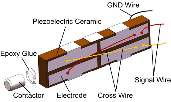
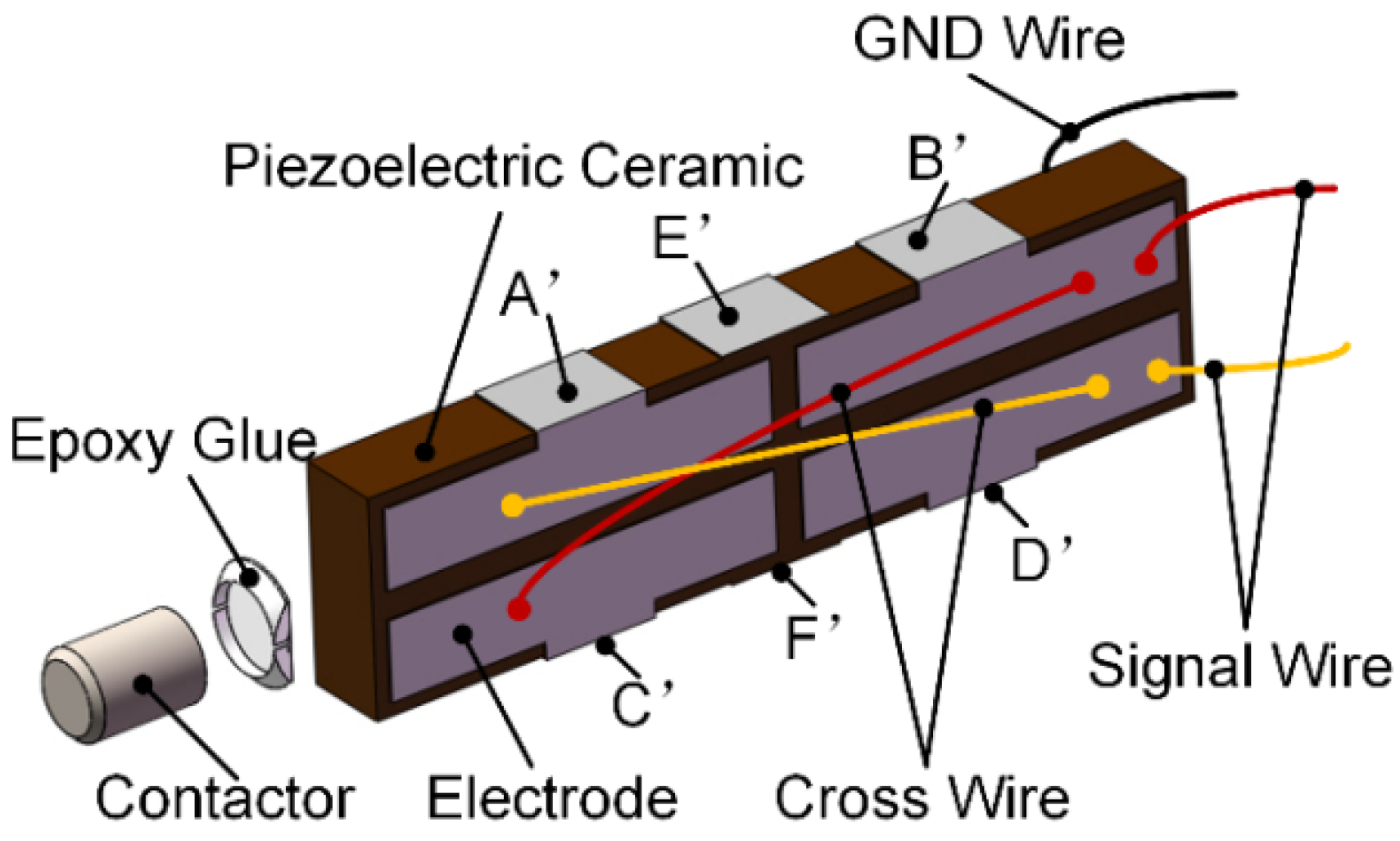
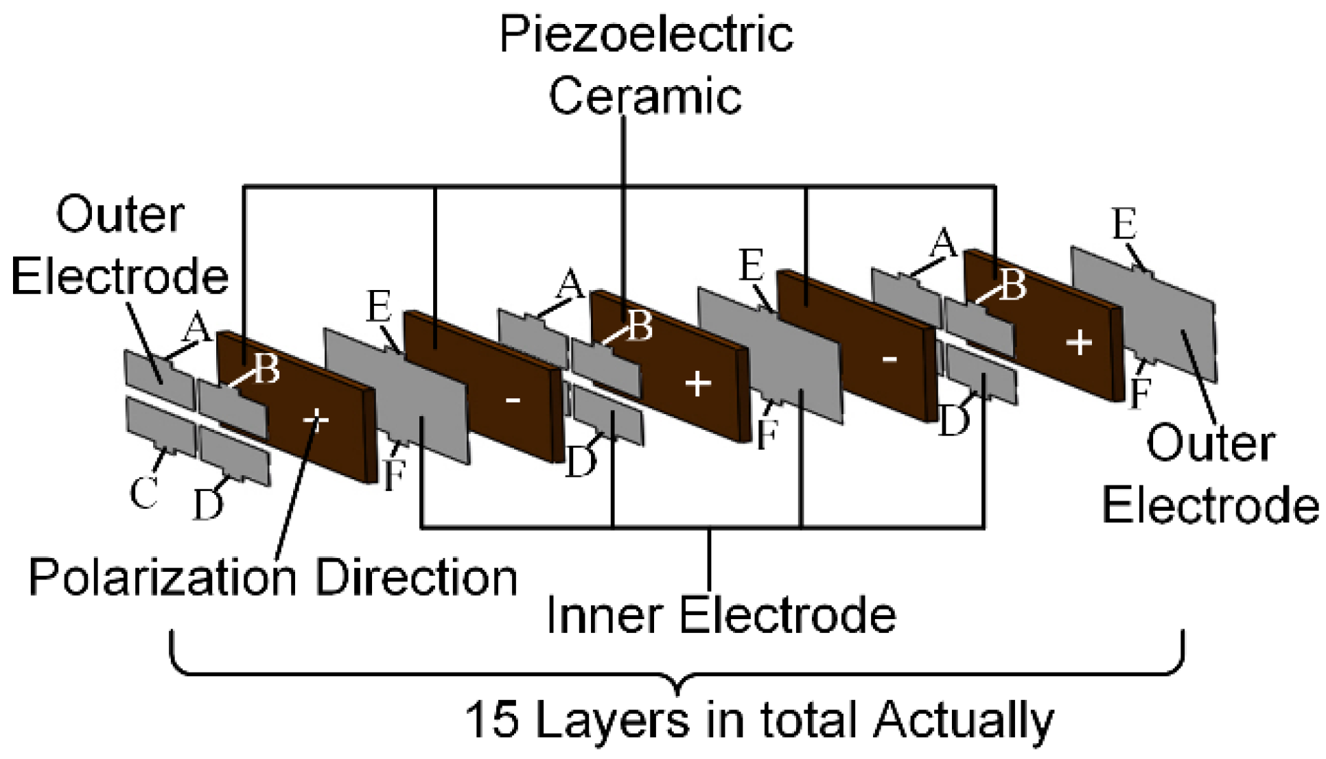
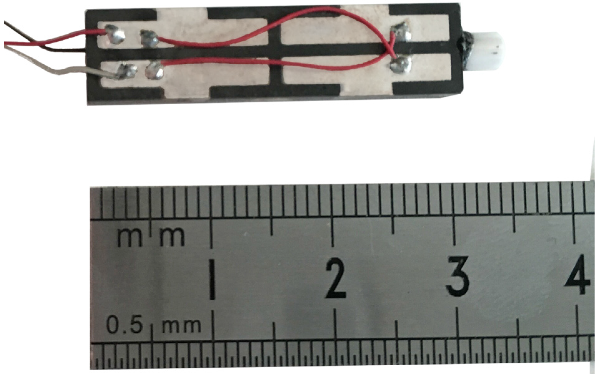
2.1. The Structure of the Piezo-Vibrator

The structure of the piezo-vibrator in the MLPA is shown in Figure 1. The piezo-vibrator consists of a block of multilayer piezoelectric ceramic (PZT-81), a contactor made from alumina ceramic (99% Al2O3), and some Teflon wires. The multilayer piezoelectric ceramic is adhered with the contactor using epoxy glue. Then cross-wires are welded to connect the cross-zone of the electrode and signal wires and a GND (ground) wire are welded to connect the electric signal applied by a power supply.
The structure of the multilayer piezoelectric ceramic is shown in Figure 2. It consists of two pieces of outer electrode, several pieces of inner electrode and thin slices of PZT-81. The structure is a sandwich one and it is fabricated with the method of low-temperature co-sintering. The electrodes can be divided into two groups based on their shapes and roles. One group, which is used as signal electrode, contains the electrodes with four separate electrode portions, and each portion has a finger to connect with the other electrodes with the same structure (namely all the fingers labeled with A are connected together using silver A’, as shown in Figure 1, and B, C, D can be done in the same manner). The other group, which is used as the GND electrode, contains the electrodes with a single piece, and each piece has two fingers to connect with other electrodes with the same structure (namely all the fingers labeled with E are connected together using silver E’, as shown in Figure 1, and F can be done in the same manner). The polarization directions of each PZT-81 layer are parallel to the thickness direction and the adjacent layers possess the opposite directions. The multilayer piezoelectric ceramic is 30 × 7.5 × 3 mm3 in size with 15 PZT-81 layers after optimizing the design, and the thickness of each layer is 200 μm. For the piezoelectric ceramic chip, the relationship between the strain and electric field intensity can be described using piezoelectric Equation (1) [20]:
x 1 = d 31 E 3
x 1 = Δ L / L
E 3 = V / t
where x1 is the strain of the piezoelectric ceramic, L is the length of the piezoelectric ceramic, ΔL is the deformation along the direction of the length when the voltage V is applied, t is the thickness of the piezoelectric ceramic, E3 is the electric field intensity applied parallel to the polarization direction.
Then ΔL can be described as the following Equation (4):
Δ L = d 31 L V / t
It can be concluded that when the thickness t decreases, the V needed decreases to get the same ΔL. This is one of the main reasons to configure the piezoelectric ceramic in a multilayer form.

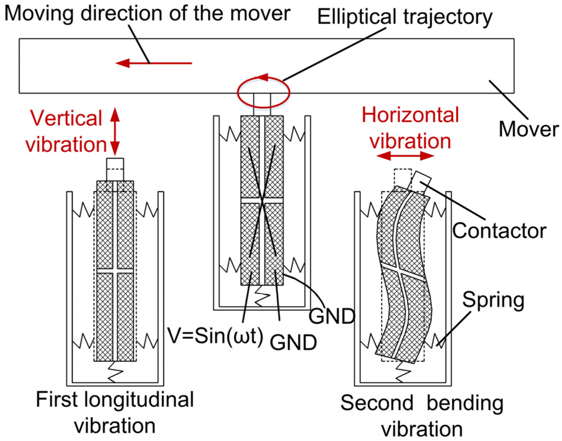
2.2. The Working Principle of the MLPA

The working principle of the MLPA is shown in Figure 3. The dimensions of the multilayer piezoelectric ceramic are designed to make the resonant frequencies of the first longitudinal (L1) and the second bending vibration (B2) modes of the ceramic as close as possible. When the voltage signals V = sin (ωt) and the GND are applied to the piezoelectric ceramic in the way shown in Figure 3, the first longitudinal and second bending vibration modes of the piezoelectric ceramic will be excited simultaneously. These two coupled vibration modes generate movements in orthogonal directions (as shown in Figure 3 “vertical vibration” and “horizontal vibration”), forming an ellipse (as shown in Figure 3 “elliptical trajectory”). The ellipse motion then pushes the mover to move in a linear direction (as shown in Figure 3 “moving direction of the mover”) through the friction between the mover and the contactor.

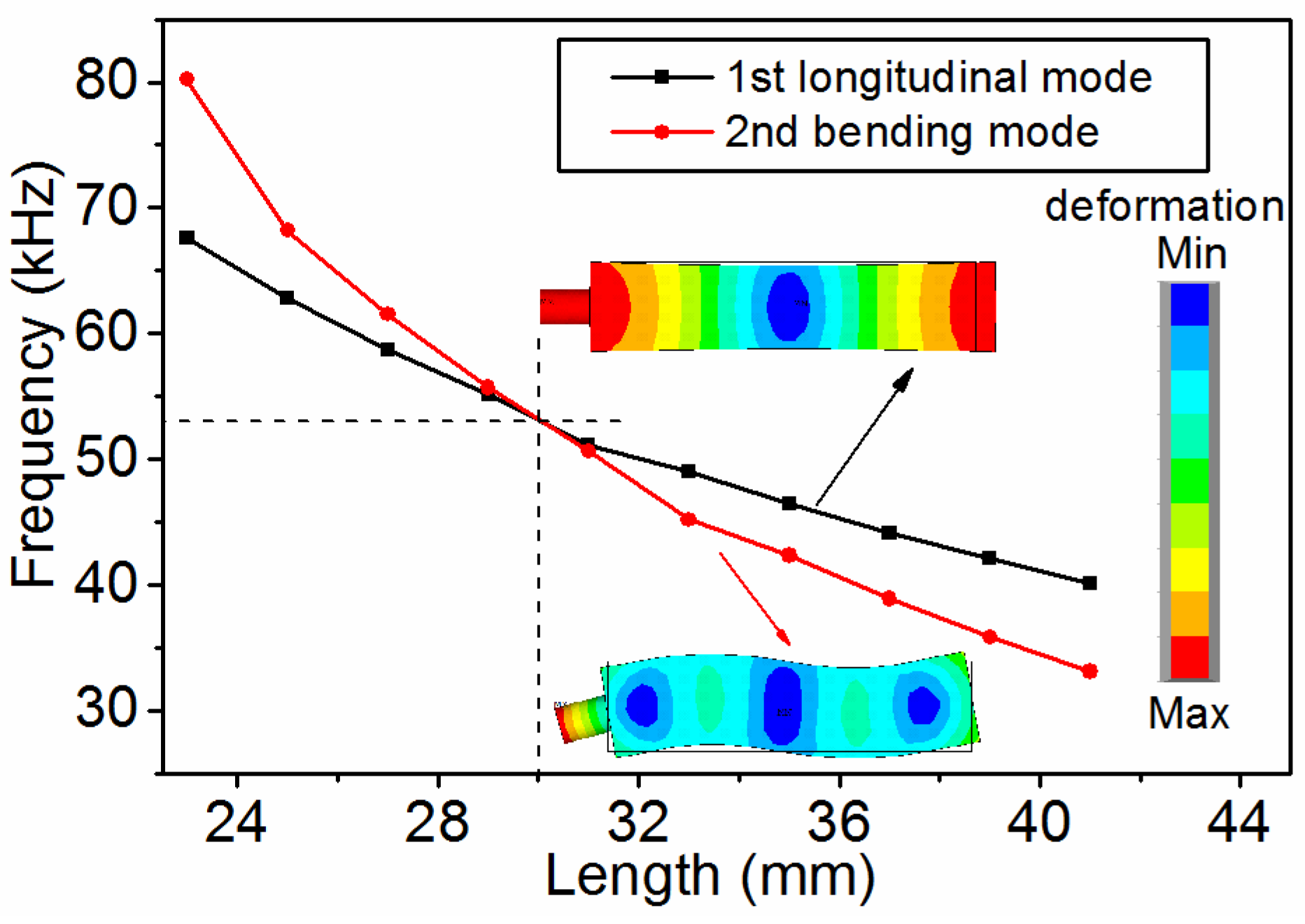
3. Design and Analysis

To optimize performance of the actuator, the dimensions of the multilayer piezoelectric ceramic need to be designed to make resonant frequencies of the L1 and the B2 modes of the ceramic as close as possible. The L1 and B2 modes’ resonance frequencies of a long bar, whose length is much larger than its width and thickness, can be approximately calculated by the following equations [21]:
f L 1 = 1 2 L 1 ρ s 11 E
f B 2 = α 2 W 2 π 12 L 2 1 ρ s 11 E
where L is the length, W is the width, α = 7.853 is a constant, and ρ is the density of the material.
To make f L 1 = f B 2 , we can calculate that L / W 5.7 . However, the PZT-81 is anisotropic and these two equations do not calculate the influence of the contactor either, so deviation would be brought in when the resonant frequencies were calculated with these two equations. From Equations (5) and (6), we can see that both frequencies of the first longitudinal and second bending modes would decrease along with the increase of L, but fB2 decreases faster. So it is possible to draw the curves of the resonant frequency vs. the length, to obtain the cross-point where the optimized length is. With the method of finite element analysis (FEA), the resonant frequencies at various dimensions can be easily obtained through modal analysis. In this study, the commercial FEA software (ANSYS 12.1, ANSYS Inc., Canonsburg, Pennsylvania, PA, USA, 2009) was used, the element type was solid 226 with option K1 set to be electro-elastic/piezoelectric. The boundary condition was set to be mechanically free. The width and thickness were set to be 7.5 mm and 3 mm, respectively, and the results are shown in Figure 4. The length at the cross-point is around 30 mm. The PZT-81 (obtained from Konghong Corporation Limited, Xi’an, China) is a kind of anisotropy material with a density ρ = 7600 kg/m3. The parameter matrixes of PZT-81 polarized in the Z+ direction are listed as follows:
(1)
Elastic matrix in flexibility form SE (unit: 10−12 m2/N):
S E = [ 11.5 3.7 4.8 0 0 0 3.7 11.5 4.8 0 0 0 4.8 4.8 13.5 0 0 0 0 0 0 30.4 0 0 0 0 0 0 31.9 0 0 0 0 0 0 31.9 ]
(2)
The matrix in d form used in ANSYS is (unit: pC/N):
d = [ 0 0 97 0 0 97 0 0 230 0 0 0 0 330 0 330 0 0 ]
(3)
Relative permittivity matrix (εT0):
ε T / ε 0 = [ 1200 0 0 0 1200 0 0 0 900 ]
According to the FEA results, the final dimensions are decided to be 30 × 7.5 × 3 mm3, as mentioned previously. The dimension of the alumina ceramic contactor is Φ 3 × 4 mm. A photo of the piezo-vibrator is shown in Figure 5.
Before making a piezoelectric vibrator, the d33 of the multilayer piezoelectric ceramic used in this study was obtained using the quasi-static d33 meter (ZJ-4NV, Beijing Oriental YUANTONG Science Technology Development Co., Ltd., Beijing, China), and the C0 was measured using the impedance analyzer (4294A, Agilent Technologies Inc., Santa Clara, CA, USA) as shown in Table 1. The number of the piezoelectric ceramic layers is 15, and the material parameter matrix d is listed in Equation (9). The value of d33 is 230 pC/N from Equation (9). In the ideal situation, the d33 of the multilayer piezoelectric ceramic should be 230 × 15 = 3450 pC/N, but the measured value is about 2290 pC/N, as shown in Table 1, 66% of the ideal value. The reasons should be that: firstly, some of the inner silver electrodes may break, as shown in Figure 6a; secondly, the influence of the pores of the ceramic on the polarization electric field is enhanced since the thickness of a single layer of the piezoelectric ceramic decreases, as shown in Figure 6b, so the polarization electric field and the polarization degree decrease.

4. Results and Discussion

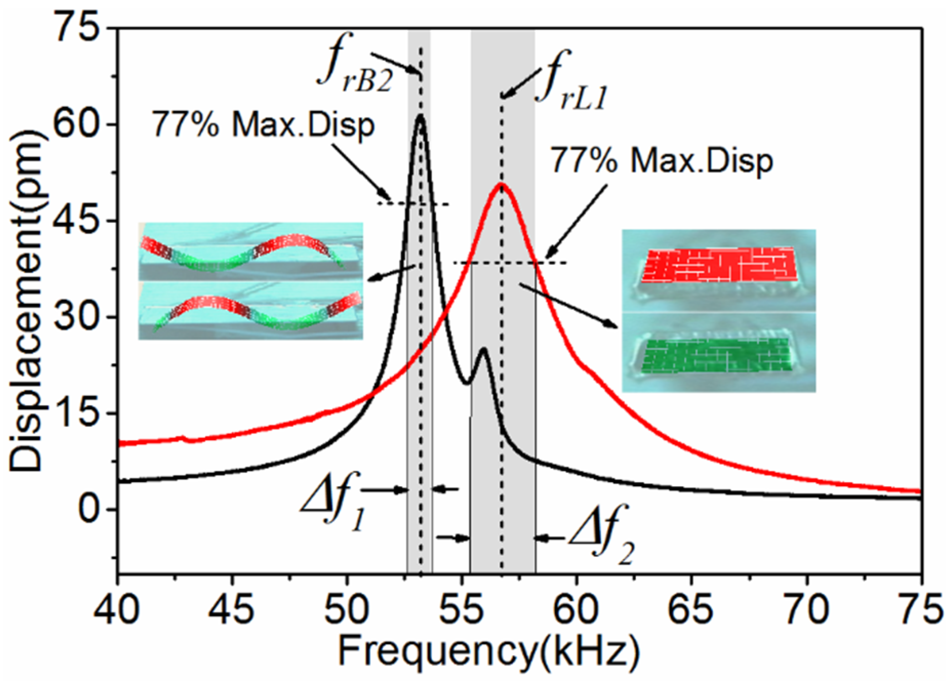
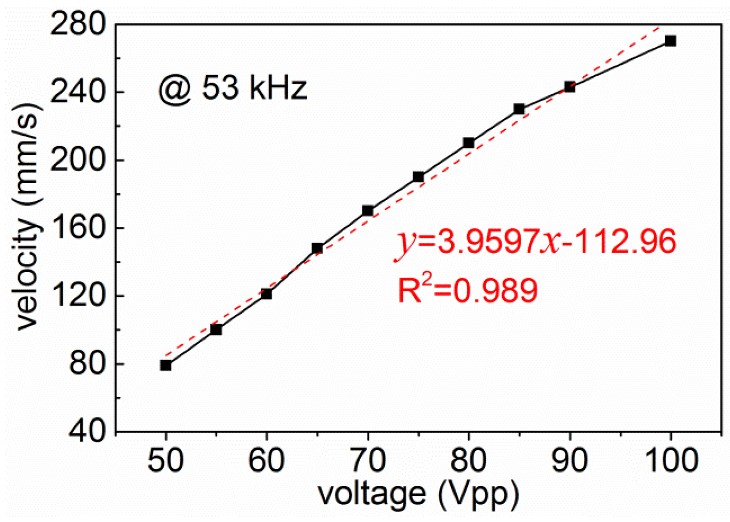
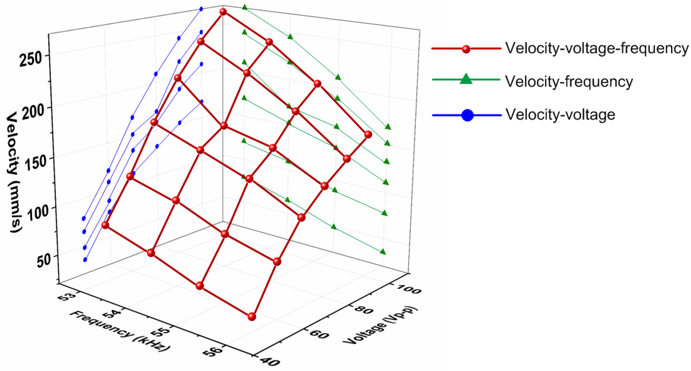
4.1. Harmonic Response Characteristics

The research of harmonic response is used to determine the steady-state response under a sine load whose frequency changes in a given range of linear structure. The harmonic response characteristic of the piezo-vibrator was gained using a scanning laser Doppler vibrometer (PSV-400-M2, Polytec Inc., Waldbronn, Germany). The result is shown in Figure 7. Part of the parameters of the vibrometer and the experimental setting were as follows:
(1) The scanning laser Doppler vibrometer can generate a laser spot size of Φ 1 mm at the surface of the measured piezo-vibrator.
(2) The resolution of the measured velocity amplitude through this equipment is 1 mm/s.
(3) The result was obtained in the condition where the piezo-vibrator was mechanically free, a condition which is the same with the boundary condition of FEA modal analysis.
The experimental result indicates that the resonant frequencies of the first longitudinal and second bending vibration modes are 56.671 and 53.1875 kHz, respectively. The frequencies are not the same as the FEA results, mainly because: firstly, the analysis ignored the influence of the inner electrodes; secondly, the actual material parameters are not totally identical to what is used in FEA due to the limitations of the measuring apparatus.
The mechanical quality factor Qm can also be calculated from the result shown in Figure 7, with Equation (10) [22]:
Q m = f r / Δ f
According to Equation (10), Q m L 1 = f r L 1 / Δ f 2 = 20 , where frL1 = 56.671 kHz, Δf2 = 2.89 kHz; Q m B 2 = f r B 2 / Δ f 1 = 50 , where frB2 = 53.1875 kHz, Δf1 = 1.062 kHz. It is known that the vibration magnitude at resonance is proportional to Qm [23]. The mechanical quality factor Qm of the two vibration modes is not equal, and QmB2 is bigger. It means that the second bending mode vibration will be more drastic, and the piezoelectric ceramic of the piezo-vibrator tends to fracture at the crest of the second bending mode shape. Figure 8 shows a fracture form of the piezo-vibrator at 53 kHz, 140 Vpp. Adopting the piezoelectric ceramic with high Qm could enhance the vibration amplitude and reduce the heat production, but would make the piezoelectric ceramic easier to fracture.

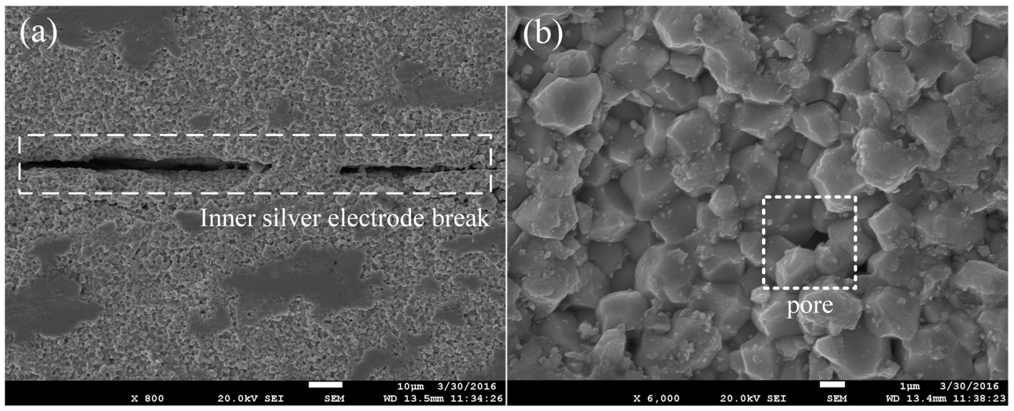
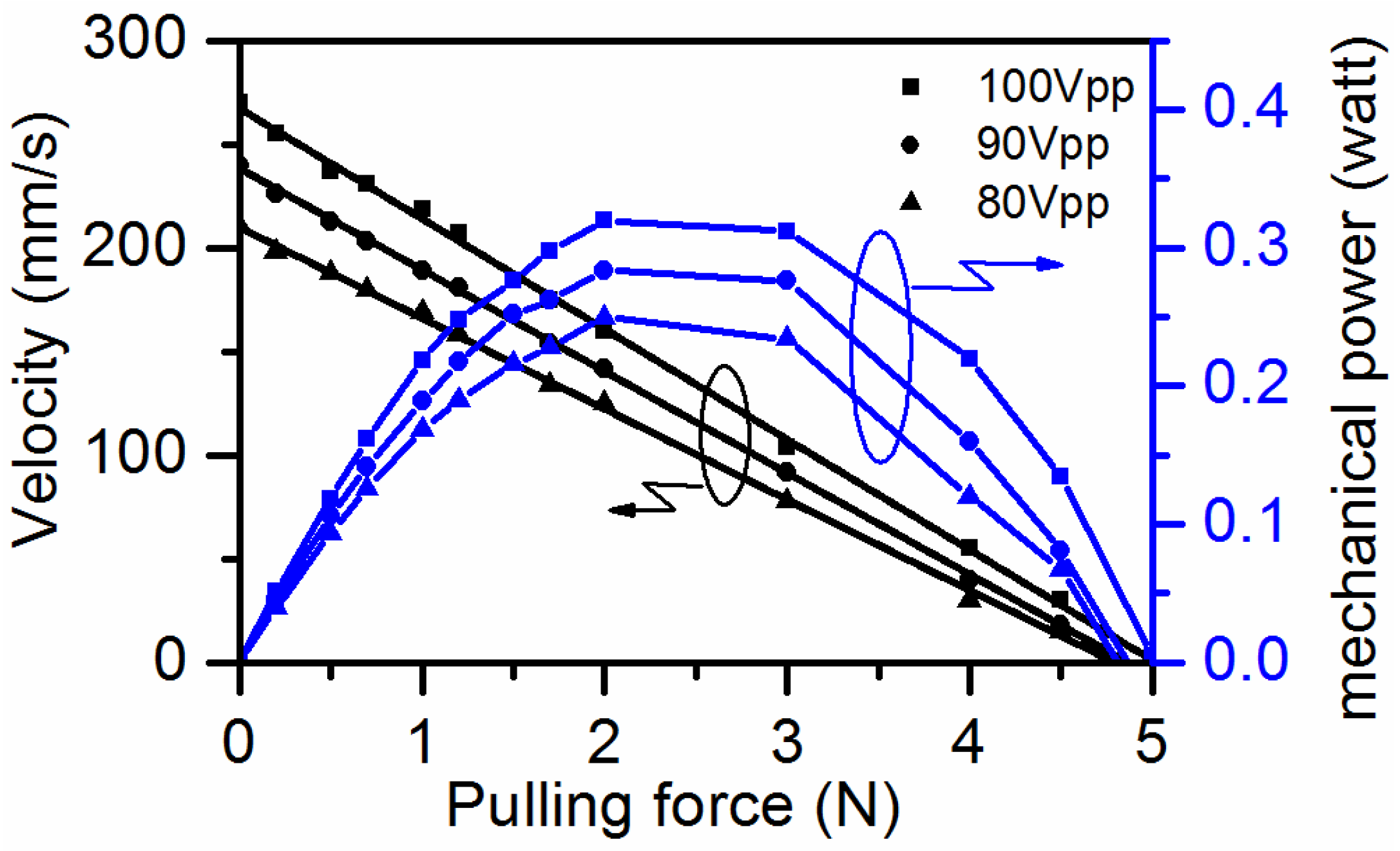
4.2. Mechanical Characteristics

The testing system of the mechanical characteristic experiments is shown in Figure 9. To form the MLPA, the piezo-vibrator was clamped by leaf springs with a clamping force of 8 N, and pressed by a pre-load spring with a pressing force of 3.5 N. The stage served as a mover, and it was pushed forward by the friction force between the friction trip and the piezo-vibrator. The weight was used to generate and measure the pulling force. The laser interferometer measure system (XL-80, Renishaw plc., Gloucestershire, London, UK) was adopted to measure the velocity of the mover.
When there is no weight, the mover’s no-load velocity can be obtained. A sinusoidal voltage with an amplitude of 80 Vpp was applied to the piezo-vibrator. The no-load velocity vs. frequency characteristics are shown in Figure 10.
The impedance-frequency curve, as shown in Figure 10, was measured using the impedance analyzer (E4990A, Agilent Technologies Inc., Santa Clara, CA, USA) to study the velocity-frequency relationship more clearly. The resonant frequencies of the first longitudinal and second bending vibration modes are nearly 54 and 52 kHz, respectively. Both the frequencies are smaller than the vibration scan results shown in Figure 7 because of the influence of the pressing force. The result shows that with the increase of the frequency, the velocity decreases firstly; when the frequency is larger than the resonant frequency of the second bending mode, the velocity gets a rapid rise to the maximum value, and then decreases again with the increase of the frequency. It can be concluded that the frequency range can be from 53 to 59 kHz to get a smooth working status. This range is wide enough to control the velocity through a controller so it is suitable for further use.
Velocity vs. frequency characteristics at different loads (hanging different weights), as shown in Figure 11, were measured at 80 Vpp to obtain more velocity-frequency characteristics in detail. The results show that the velocity of the stage decreased with the increase of the load, but the regularity was not changed.
Figure 12 shows the relationship between no-load velocity of the stage and the applied voltage peak-peak value at frequency of 53 kHz. The velocity increases almost linearly with the voltage peak-peak value, which indicates the relatively well controllability of the actuator compared to some of the single piezoelectric ceramic actuators [6,14]. The starting voltage is 50 Vpp, and the starting velocity is 80 mm/s at 53 kHz. To get a smaller starting velocity, the frequency needs to be changed according to the velocity-frequency curve shown in Figure 10, in the frequency range from 53 to 59 kHz.
Figure 13 shows a relationship between velocity of the stage vs. the applied voltage peak-peak value and frequency, the frequency was chosen in the range of 53–56 kHz, and the voltage peak-peak value changed from 50 to 100 Vpp, the velocity-voltage and the velocity-frequency projections are shown in Figure 13.
The velocity vs. pulling force characteristics are shown in Figure 14, and the pulling force was obtained through a hanging weight. Three different amplitudes of the sinusoidal voltage, 100, 90, and 80 Vpp, were adopted and the frequency was fixed to 53 kHz in this study. It turns out that: firstly, the maximum velocity of this actuator is 270 mm/s and the maximum pulling force is 5 N; secondly, the curve of the velocity and pulling force can be fit into a line, showing good linearity; thirdly, the velocity-pulling force lines at various voltages are not parallel, and the ratio between the pulling force (F) and the velocity (V), namely F/V, is bigger. Through Figure 14, the mechanical power of the piezoelectric actuator can be obtained (the mechanical power equals the product of the velocity and the pulling force). From the curve of the mechanical power versus the pulling force, as shown in Figure 14, it can be seen that the maximum mechanical power of the actuator we proposed was 0.32 W. The inertia of the stage was ignored when we calculated the pulling force; thus, the power when there was no pulling force was zero. The mass of the vibrator is 5.49 g, and then it can be calculated that ratio of the mechanical power and mass is 58.3 W/kg.

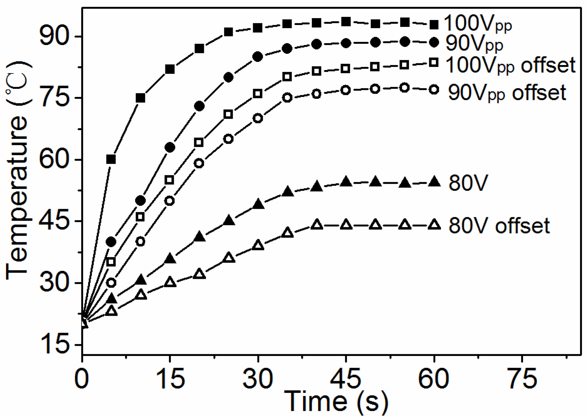
4.3. Temperature Characteristics

Figure 15 shows the surface temperature change of the piezo-vibrator. The temperature was measured at the following settings and conditions:
(1) The apparatus used was an infrared thermometer (Optris CT-LT, Optris GmbH, Berlin, Germany).
(2) The temperature was measured when the mover was in locked-rotor for 60 s.
(3) The ambient temperature was 20 °C.
(4) The voltage applied to the piezo-vibrator was V 1 = ( A p p / 2 ) sin ( 2 π f t ) , where App was set to be 100, 90, 80 Vpp, respectively, and f was set to 53 kHz.
The result shows that the vibrator generated lots of heat which caused a high temperature on the vibrator surface. The surface temperature then tended to become steady. With the decreasing of the input voltage, the heat generation was reduced, and when the input voltage was decreased to 80 Vpp, the heat generation was reduced more drastically. When an alternating voltage (V1) is applied to the multilayer piezoelectric ceramic, the internal ferroelectric domains will turn over continuously. If we applied the voltage to make the ferroelectric domains turn over discontinuously, the heat generation may be less; thus, experiments with offset voltage applied were conducted. The offset signal was set to be V 2 = ( A p p / 2 ) sin ( 2 π f t ) + A p p / 2 . The actuator studied can run smoothly using the offset voltage signal and the temperature change decreased compared to the non-offset voltage signal; however, the decrease was not obvious.
The heat productivity and temperature rise bring many disadvantages, such as frequency drift which causes instability of actuators, efficiency loss, and aging of piezoelectric ceramic and epoxy, which decreases the lifespan of the actuators. The main reasons for the high temperature rise of this multilayer piezoelectric ceramic vibration can be concluded as follows: because of the multilayer configuration, the mechanical quality factor Qm decreases to cause an increase in the mechanical loss, and the dielectric loss increases. Both the losses transform into heat and cause the increase of the temperature. Meanwhile, since the thickness of the layers of the piezoelectric ceramic cannot be fabricated exactly the same, the different thicknesses lead to different deformations along the length and width directions, which causes internal friction between layers.
To reduce the temperature rise, a high Qm piezoelectric ceramic needs to be developed and the thickness uniformity of the piezo-layers should be improved.

5. Conclusions

In this study, an ultrasonic linear piezoelectric actuator based on multilayer PZT was researched. We analyzed the working principle and designed the dimensions of the piezo-vibrator based on the method of FEA. Experiments on harmonic response, mechanical characteristics, and temperature characteristics of the actuator were conducted. The results of the experiments show that the actuator can work smoothly, reaching a maximum velocity of 270 mm/s and a maximum pulling force of 5 N at 100 Vpp. The maximum ratio of the mechanical power and mass is 58.3 W/kg for this actuator. The temperature characteristic shows that the temperature of the actuator rises rapidly and tends to saturate. Further research will focus on the temperature rise problem, based on both enhancing the Qm to reduce the heat production and adopting suitable cooling methods.

Acknowledgements

This research is financially supported by Basic Scientific Research Program of China, the Specialized Fund for Science & Technology Innovation of Foshan (Grant no. 2013AH100031), and Special Materials (Grant no. JPPT-125-4-063). The authors are indebted to these financial supports to accomplish this research and acknowledge the collaboration of Paihe Science & Technology Holding Co., Ltd. Beijing, China.

Author Contributions

All authors conceived and designed the experiments and analyzed the data; Songmei Yuan and Yanqiang Zhao accomplished the finite element analysis; Xiangcheng Chu contributed to the theoretical analysis and modified this paper. Cong Zhu and Zuojin Zhong performed the experiments; all authors contributed to the writing of the paper.

Conflicts of Interest

The authors declare no conflict of interest.

References

  1. Snitka, V. Ultrasonic actuators for nanometre positioning. Ultrasonics 2000, 38, 20–25. [Google Scholar] [CrossRef]
  2. Bein, T.; Breitbach, E.J.; Uchino, K. A linear ultrasonic motor using the first longitudinal and the fourth bending mode. Smart Mater. Struct. 1997, 6, 619–627. [Google Scholar] [CrossRef]
  3. Chu, X.C.; Wang, J.W.; Yuan, S.M.; Li, L.T.; Cui, H.C. A screw-thread-type ultrasonic actuator based on a langevin piezoelectric vibrator. Rev. Sci. Instrum. 2014, 85, 065002. [Google Scholar] [CrossRef] [PubMed]
  4. Liu, Y.X.; Chen, W.S.; Feng, P.L.; Liu, J.K. A linear piezoelectric actuator using the first-order bending modes. Ceram. Int. 2013, 39, S681–S684. [Google Scholar] [CrossRef]
  5. Yuan, S.M.; Zhu, C.; Chu, X.C.; Zhao, Y.Q.; Amin, M.; Fan, Y.L. A novel linear piezoelectric actuator with two working principles of standing and traveling wave vibration mode. AIP Adv. 2015, 5, 107213. [Google Scholar] [CrossRef]
  6. Li, X.T.; Chen, J.G.; Chen, Z.J.; Dong, S.X. A high-temperature double-mode piezoelectric ultrasonic linear motor. Appl. Phys. Lett. 2012, 101, 072902. [Google Scholar] [CrossRef]
  7. Liu, Y.X.; Chen, W.S.; Xu, D.M.; Feng, P.L.; Liu, J.K. Improvement of a rectangle-shape linear piezoelectric motor with four driving feet. Ceram. Int. 2015, 41, S594–S601. [Google Scholar] [CrossRef]
  8. Yun, C.H.; Waston, B.; Friend, J.; Yeo, L. A piezoelectric ultrasonic linear micromotor using a slotted stator. IEEE Trans. Ultrason. Ferroelectr. Freq. Control 2010, 57, 1868–1874. [Google Scholar] [PubMed]
  9. Vyshnevsky, O.; Kovalev, S.; Wischnewskiy, W. A novel, single-mode piezoceramic plate actuator for ultrasonic linear motors. IEEE Trans. Ultrason. Ferroelectr. Freq. Control 2005, 52, 2047–2053. [Google Scholar] [CrossRef]
  10. Hemsel, T.; Wallaschek, J. Survey of the present state of the art of piezoelectric linear motors. Ultrasonics 2000, 38, 37–40. [Google Scholar] [CrossRef]
  11. Liu, Y.X.; Liu, J.K.; Chen, W.S.; Feng, P.L. A square-type rotary ultrasonic motor using longitudinal modes. J. Electroceram. 2014, 33, 69–74. [Google Scholar] [CrossRef]
  12. Chen, Z.J.; Li, X.T.; Chen, J.G.; Dong, S.X. A square-plate ultrasonic linear motor operating in two orthogonal first bending modes. IEEE Trans. Ultrason. Ferroelectr. Freq. Control 2013, 60, 115–120. [Google Scholar] [CrossRef] [PubMed]
  13. Shi, Y.L.; Zhao, C.S. A new standing-wave-type linear ultrasonic motor based on in-plane modes. Ultrasonics 2011, 51, 397–404. [Google Scholar] [CrossRef] [PubMed]
  14. Wan, Z.J.; Hu, H. Modeling and experimental analysis of the linear ultrasonic motor with in-plane bending and longitudinal mode. Ultrasonics 2014, 54, 921–928. [Google Scholar] [CrossRef] [PubMed]
  15. Friend, J.; Umeshima, A.; Ishii, T.; Nakamura, K.; Ueha, S. A piezoelectric linear actuator formed from a multitude of bimorphs. Sens. Actuators A 2004, 109, 242–251. [Google Scholar] [CrossRef]
  16. Saigoh, H.; Kawasaki, M.; Maruko, N.; Kanayama, K. Multilayer piezoelectric motor using the first longitudinal and the second bending vibrations. Jpn. J. Appl. Phys. 1995, 34, 2760–2764. [Google Scholar] [CrossRef]
  17. Funakubo, T.; Tsubata, T.; Taniguchi, Y.; Kumei, K.; Fujimura, T.; Abe, C. Ultrasonic linear motor using multilayer piezoelectric actuators. Jpn. J. Appl. Phys. 1995, 34, 2756–2759. [Google Scholar] [CrossRef]
  18. Ganor, Z.; Rafaeli, I.; Shiv, L.; Karasikov, N. Multilayer Piezoelectric Motor. U.S. Patent 7,075,211, 31 May 1999. [Google Scholar]
  19. Nanomotion. Available online: http://www.Nanomotion.Com/wp-content/uploads/2015/09/hr00458000–00-hr-motor-user-manual.Pdf (accessed on 3 September 2015).
  20. Ueha, S.; Tomikawa, Y. Ultrasonic motors: Theory and applications; Oxford University Press: London, UK, 1994. [Google Scholar]
  21. Guo, M.S.; Dong, S.X.; Ren, B.; Luo, H.S. A double-mode piezoelectric single-crystal ultrasonic micro-actuator. IEEE Trans. Ultrason. Ferroelectr. Freq. Control 2010, 57, 2596–2600. [Google Scholar] [PubMed]
  22. Chang, L. Foundations of mems; Prentice Hall: Upper Saddle River, Bergen, NJ, USA, 2011. [Google Scholar]
  23. Guo, M.S.; Hu, J.H.; Zhu, H.; Zhao, C.S.; Dong, S.X. Three-degree-of-freedom ultrasonic motor using a 5-mm-diameter piezoelectric ceramic tube. IEEE Trans. Ultrason. Ferroelectr. Freq. Control 2013, 60, 1446–1452. [Google Scholar]
Figure 1. Structure of the piezo-vibrator in the MLPA (multilayer linear piezoelectric actuator), A’, B’, C’, D’, E’ and F’ are silver.
Applsci 06 00225 g001
Figure 2. Schematic diagram for the assembly of electrode and piezoelectric ceramic layers, A, B, C, D, E and F stand for the fingers on the separate electrode portions.
Applsci 06 00225 g002
Figure 3. Working principle of the multilayer piezoelectric actuator.
Applsci 06 00225 g003
Figure 4. Modal frequencies at various lengths of PZT (piezoelectric lead zirconate titanate) block.
Applsci 06 00225 g004
Figure 5. Photo of the piezoelectric vibrator.
Applsci 06 00225 g005
Figure 6. SEM photo of the cross-section of the multilayer piezoelectric ceramic. (a) Cross-section 800×; (b) Cross-section 6000×.
Applsci 06 00225 g006
Figure 7. Vibration scan results of the stator using Doppler vibrometer.
Applsci 06 00225 g007
Figure 8. Fracture form of the piezo-vibrator.
Applsci 06 00225 g008
Figure 9. Testing system of velocity vs. tension.
Applsci 06 00225 g009
Figure 10. Impedance and velocity characteristic vs. frequency of the actuator.
Applsci 06 00225 g010
Figure 11. Velocity vs. frequency characteristics at different loads.
Applsci 06 00225 g011
Figure 12. Velocity of the stage vs. applied voltage peak-peak value.
Applsci 06 00225 g012
Figure 13. Velocity of the stage vs. applied voltage peak-peak value and frequency.
Applsci 06 00225 g013
Figure 14. Velocity vs. pulling force at various voltages.
Applsci 06 00225 g014
Figure 15. Surface temperature change vs. time at various voltages.
Applsci 06 00225 g015
Table 1. The measured d33 and the C0 of the multilayer piezoelectric ceramic.
Zone1234
d33 (pC/N)2336233822522236
C0 (nF)28.528.727.928.0

