Article

In Situ Test Study on Freezing Scheme of Freeze-Sealing Pipe Roof Applied to the Gongbei Tunnel in the Hong Kong-Zhuhai-Macau Bridge

1
Key Laboratory of Geotechnical and Engineering of Ministry of Education, Department of Geotechnical Engineering, Tongji University, Shanghai 200092, China
2
The Administration Center of Zhuhai Link Line Project of Hong Kong-Zhuhai-Macao Bridge, Zhuhai 519030, China
*
Author to whom correspondence should be addressed.
Appl. Sci. 2017, 7(1), 27; https://doi.org/10.3390/app7010027
Submission received: 30 October 2016 / Revised: 9 December 2016 / Accepted: 19 December 2016 / Published: 27 December 2016
(This article belongs to the Special Issue Advances in Thermal System Analysis and Optimization)

Abstract

:
In order to solve the water sealing problem of soil between pipes of long distance curved pipe-jacked technology, Freeze-Sealing Pipe Roof (FSPR) as an innovative pre-supporting method in tunnel engineering is being applied to the Gongbei Tunnel in the Hong Kong-Zhuhai-Macau Bridge. The definition of FSPR is that large diameter steel pipes are laid out in a circle around the cross section of tunnel in advance, then the artificial ground freezing method is adopted to freeze soil between steel pipes to form water-sealing curtain. An effective freeze control system, which contains master freezing tubes, enhancing freezing tubes and limiting freezing tubes, is established for building up the frozen soil curtain, maintaining its stability during excavation and controlling the volume of frozen soil to limit frost heave dynamically. An in-situ test was carried out to explore the optimal freezing scheme and control mode. The results of the test show that the principal freezing scheme of the solid pipe with hollow pipe as a complement is the most optimal scheme in active freezing phase of the real construction. Meanwhile, cold control mode is suggested to control frost heave in maintained freezing phase. The conclusions have important guiding significance for this kind of engineering construction.

1. Introduction

With the increasing complexity of the underground construction environment, the construction technology is becoming more and more complex and difficult. Shallow-buried underground excavation, as a major underground construction method, has an important role in tunnel engineering and its development relies on an auxiliary construction method. Among them, pre-supporting method is widely applied in shallow-buried underground excavation, because of simple technology and low cost. The pipe-roofing method is a primary method of pre-supporting. As the complexity of underground environment increases, it is difficult to meet the requirements of project quality with only one auxiliary method, especially in the construction of large cross-section tunnel with a rich aquifer. Therefore, the combination of pipe-roofing method and different innovative methods have been carried out to ensure the safety of construction, which is proposed by many scholars. As is known, combining a variety of engineering methods to realize the complementary advantages of the system is an effective way to solve engineering problems. Some successful applications related to the pipe roofing method are as follows: ESA (endless self-advancing method), FJ (front jacking method), RBJ (roof-box jacking method), Okumura R&C method, TULIP method [1], SR-J method [2], SR-JR method [3], New Tubular Roof method [4], etc. These pre-supporting methods provided good construction condition for excavation, but exposed the weakness of water sealing, especially in long distance curved pipe-jacked projects. However, the Freeze-Sealing Pipe Roof (FSPR) method as a new shallow-buried underground excavation technology can solve this issue well.
In order to minimize the impact of transportation caused by construction in the Gongbei Tunnel in the Hong Kong-Zhuhai-Macau Bridge, shallow excavation is applied in the port line tenders with a length of 255 m. However, it is difficult to provide a good condition for the open-cut method, and the excavation part of the tunnel lies between soft soil and medium soft soil. Moreover, it is wasteful to construct with shield method in such large cross section and short-distance road tunnel. Therefore, shallow excavation scheme with pipe-roof method was adopted. A conventional water sealing method is to use sealing latch between steel pipes, but the water sealing effect of pipe-roofing cannot be guaranteed for such curve pipes. Therefore, the artificial ground freezing method was applied to ensure water sealing as an environmental method, compared with general slurry injection technology.
The Freeze-Sealing Pipe Roof (FSPR) method is an auxiliary method combining the pipe roof method and artificial freezing method [5], where the steel pipe roof mainly plays a role in load bearing and the frozen soil curtain mainly plays a role in water sealing. FSPR makes full use of the advantages of the pipe roof method and artificial ground freezing method. On one hand, FSPR has little effect on the surrounding environment [6], on the other hand, the advantage of adaptability, controllability and strong sealing property of the freezing method can be fully used to solve the water sealing problem between steel pipes. FSPR, as a shallow-buried underground excavation method was first applied in the Gongbei Tunnel in the Hong Kong-Zhuhai-Macau Bridge [7,8].
Only a few researches have undertaken in this field. Moriuchi briefly studied the mechanical properties between frozen soil and steel pipes and the interaction between them [9,10,11]. A similar method has been applied in few projects, which have only appeared in China and Germany [5], where frozen soil curtain mainly played a role in load bearing, which is essentially different from the method applied in the Gongbei Tunnel. There is an obvious difference between the pipe shed method and pipe roof method. Steel pipes are mainly regarded as load bearing structures in the pipe shed method, yet frozen soil is mainly regarded as a load bearing structure in the pipe roof method.
Xiangdong Hu‘s research group has done a lot of research on the design concept of the freezing method and the reliability of water sealing for the FSPR method through numerical simulation and model test. Siyuan She et al. [12] and Xiangdong Hu et al. [13] carried out a preliminary study of the freezing scheme in the FSPR method based on unsteady conjugate heat transfer theory. Yang Wang [14] analyzed the mechanical properties of steel pipe-frozen soil composite structure by laboratory test. Jin Chen [15] and Xiangdong Hu et al. [16] made a large scaled model test of FSPR on freezing scheme. The results of all these studies were considered in the project design [17,18]. Xiangdong Hu et al. [19] briefly described part of field test of this FSPR. This paper aims to explore the optimal freezing scheme of FSPR and optimal control modes of frost heave by an in-situ test, the study results have been applied to actual construction.

2. Experimental Program

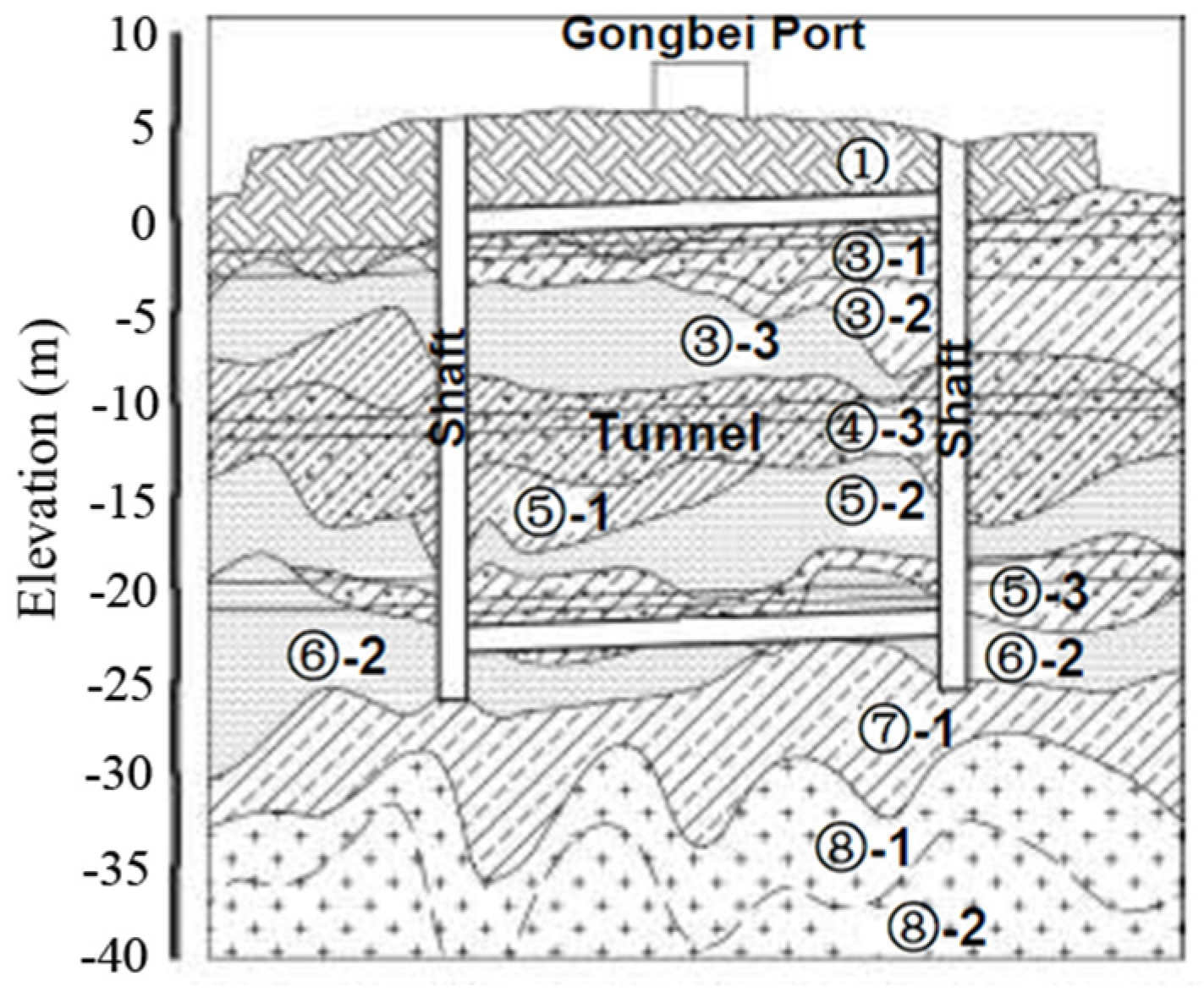
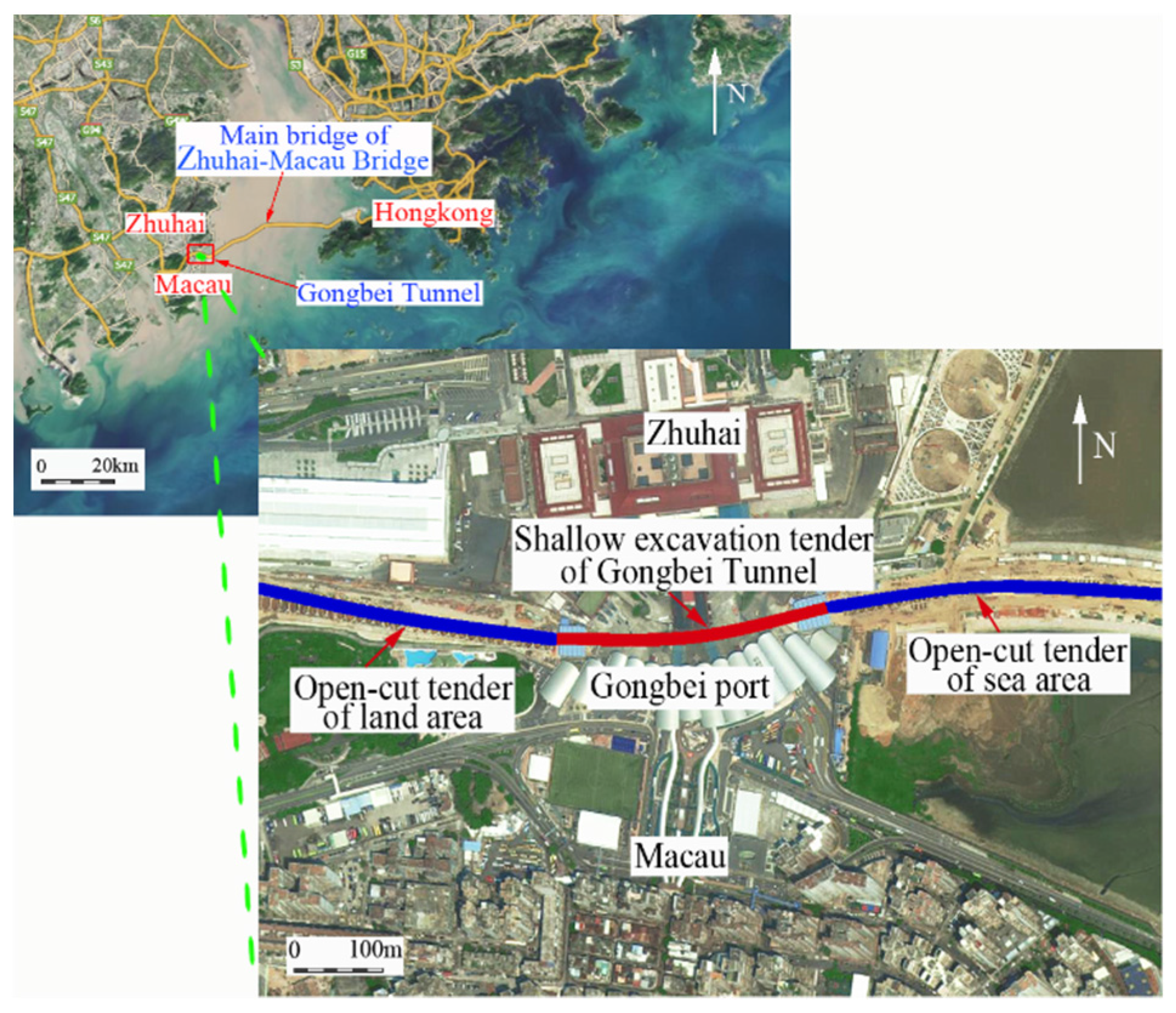
2.1. Engineering Background

2.1.1. Project Profile

The Hong Kong-Zhuhai-Macau Bridge is an ongoing construction project which consists of a series of bridges and tunnels, which cross the Lingdingyang channel connecting Hong Kong, Macau and Zhuhai, three major cities on the Pearl River Delta in China. The Gongbei Tunnel in the Hong Kong-Zhuhai-Macau Bridge is a key project of Zhuhai connection of this bridge with a length of 2705 m.
The Gongbei Tunnel is a critical link of the Hong Kong-Zhuhai-Macau Bridge. It is a double deck, three-lane in each direction roadway tunnel with a length of 255 m, including an 88 m transitional curve with a curvature ranging from 886 m to 906 m and a 157 m circular curve with a curvature of 886 m, shown in Figure 1. The excavation cross-sectional area is 18.8 m in width and 20.6 m in height, which represents the largest single tunnel excavation in China. The tunnel is buried within soft sandy and silty clay about 4 to 5 m below the ground surface at the Gongbei customer port. The construction steps include pipe jacking, ground freezing and excavation.
Figure 2 shows the geological profile of the Gongbei tunnel. The ground surface is roughly at an elevation of 5 m and the top of sound rock is about at an elevation below −40 m, leaving more than 45 m thickness of soils and decomposed rock. Below the miscellaneous fill (stratum①), the natural soils mostly consist of clay and silt with interlayers of sands, deposited in a marine environment during the geological history. The tunnel is designed to be excavated in the stratum①, miscellaneous fill; stratum③-1, very soft organic clay and silt; stratum③-2, very soft to soft clay and silt; stratum③-3, loose to medium dense coarse sand; stratum④-3, soft to medium stiff sandy clay and silt; stratum⑤-1, soft sandy clay and silt; stratum⑤-2, medium dense fine sand; stratum⑤-3, medium stiff sandy clay and silt; and stratum⑥-2, medium dense fine sand. The tunnel is underlain by stratum⑦-1, decomposed rock; stratum⑧-1, completely weathered bedrock; stratum⑧-2, heavily weathered bedrock, and sound bedrock, granite. The groundwater table is close to the ground surface with elevation varying from 1.9 m to 3.5 m.
The soil layer related to in-situ test was stratum③-1 and ③-2, relevant soil parameters was shown in Table 1.
The poor ground conditions, shallow burial depth, large opening area, small alignment curvature, complicated site conditions, and political sensitivity of the construction site make the Gongbei Port tunnel the most challenging engineering task of the Hong Kong-Zhuhai-Macau Bridge project.

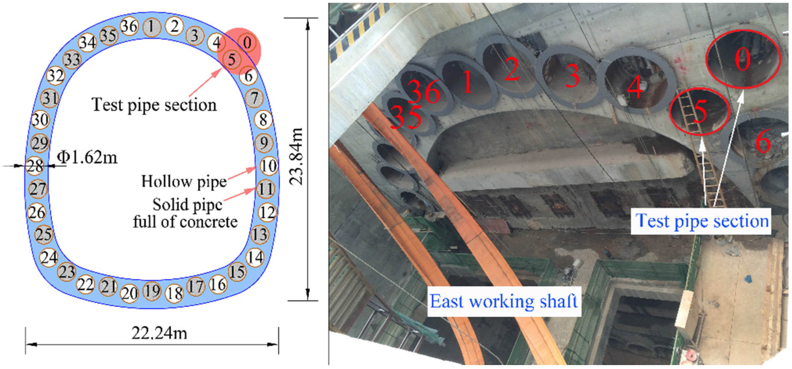
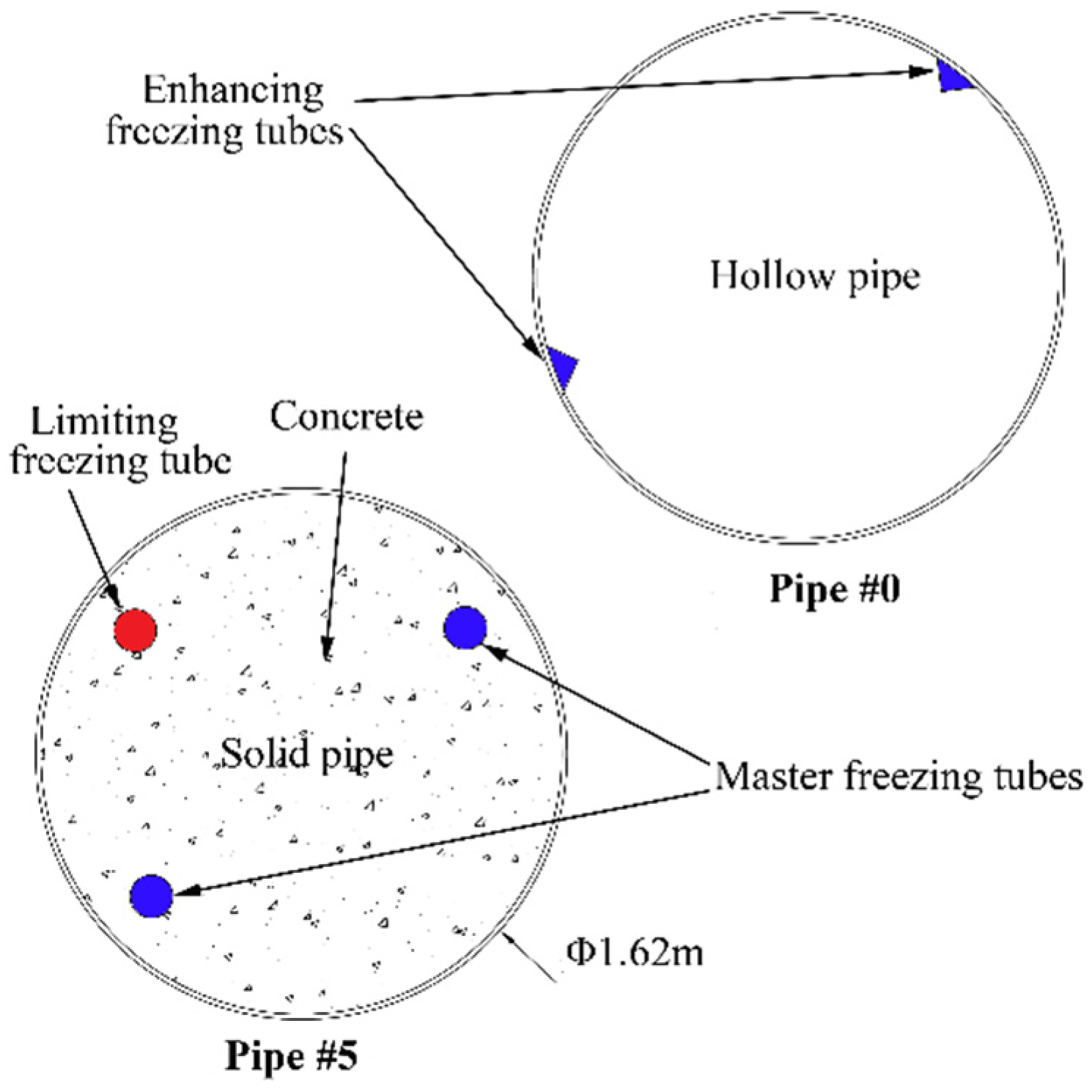
2.1.2. Pipe Roof Design

Figure 3 shows the original design of the pipe roof which consists of 36 pieces of 1620 mm diameter steel pipes around the circumference of excavation. The spacing between the pipe edges ranges from 35.5 to 35.8 cm. In the cross section of tunnel circumference, the odd number roof pipes are shifted inward by 30 cm along the radial direction of tunnel with respect to the even diameter pipes. The length of the pipe roof is about 255 m. Two test pipes are shown in the figure below.

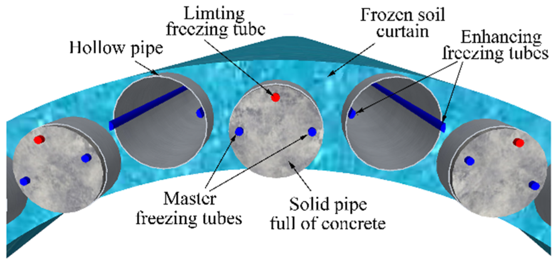
2.1.3. Freezing Design

The freezing design is mainly based on the concept of "freeze-up, anti-weakening, frost-heave control", which is proposed by Xiangdong Hu et al. [16], Considering the non-uniformity of the thermal conductivity caused by hollow and solid staggered pipes, an innovative freezing scheme is proposed. Master freezing tubes and limiting freezing tubes were installed in the solid pipes, while enhancing freezing tubes were installed in hollow pipes. The layout of all freezing tubes is shown in Figure 4. There are three types of freezing tubes in the tests. The master freezing tubes of circular shape are popular in freezing construction. Two other tubes demonstrate innovative designs. The function of the limiting freezing tube is to limit the expansion of frozen soil is thickness by recycling brine with relatively high temperature. Enhancing freezing tubes are close to the inner surface of the hollow pipe, so it will have a better effect in improving freezing effects. Detailed arrangement of freezing tubes in each pipe-jacking was mentioned in Siyuan She’s paper [12]. The design thickness of frozen soil is 2–2.6 m.

2.2. Test Content and Scheme

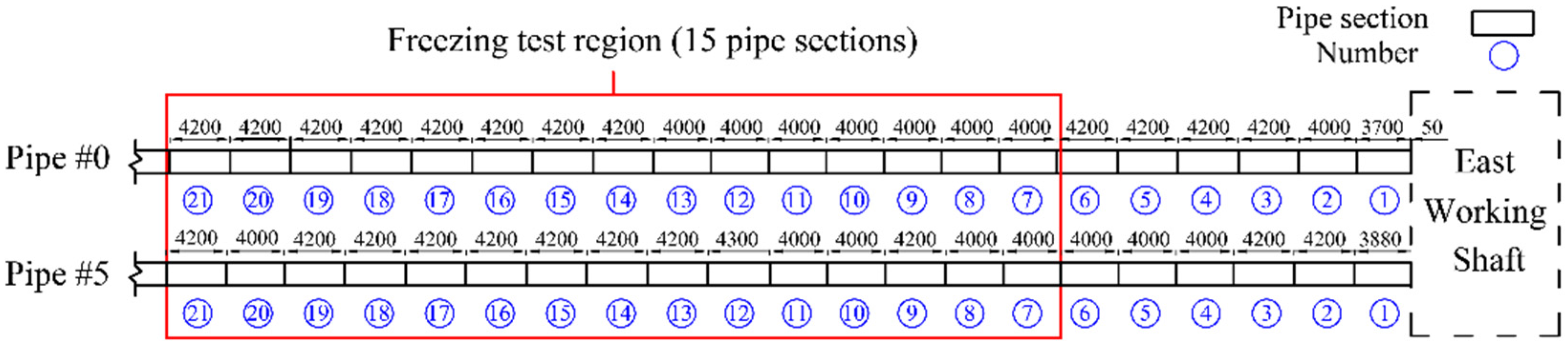
2.2.1. Test Pipe Section

In-situ test was carried out in an earlier completed pipe (#5 pipe) and a test pipe (#0 pipe), which is shown in Figure 3. There are 15 examples of pipe-jacking in the transition curve section in the test, arranged along the longitudinal direction of the pipe-roofing. Different freezing tests are carried out in these pipes. There are two working shafts, providing the construction condition of pipe jacking, receiving and tunnel excavation. Meanwhile, in order to reduce the impact of working shaft on the freezing test, the test region is starting from the 7th pipe counted from the East working shaft. Figure 5 clearly shows the location of the test region of the pipe-jacking and the units of the pipes. Each pipe-jacking is made of Q235BZ with a length of 4000–4200 mm.
Based on the freezing scheme and the actual operating condition, the freezing tubes arrangement in the #5 solid pipe and the #0 hollow pipe mentioned above are as follows: two master freezing tubes and one limiting freezing tube in #5 pipe, filled with micro-expansion concrete; two enhancing freezing tubes in pipe #0, shown in Figure 6. The function of each freezing tube was illustrated in freezing design part. The diameter of the steel pipe is 1620 mm and the thickness is 20 mm.

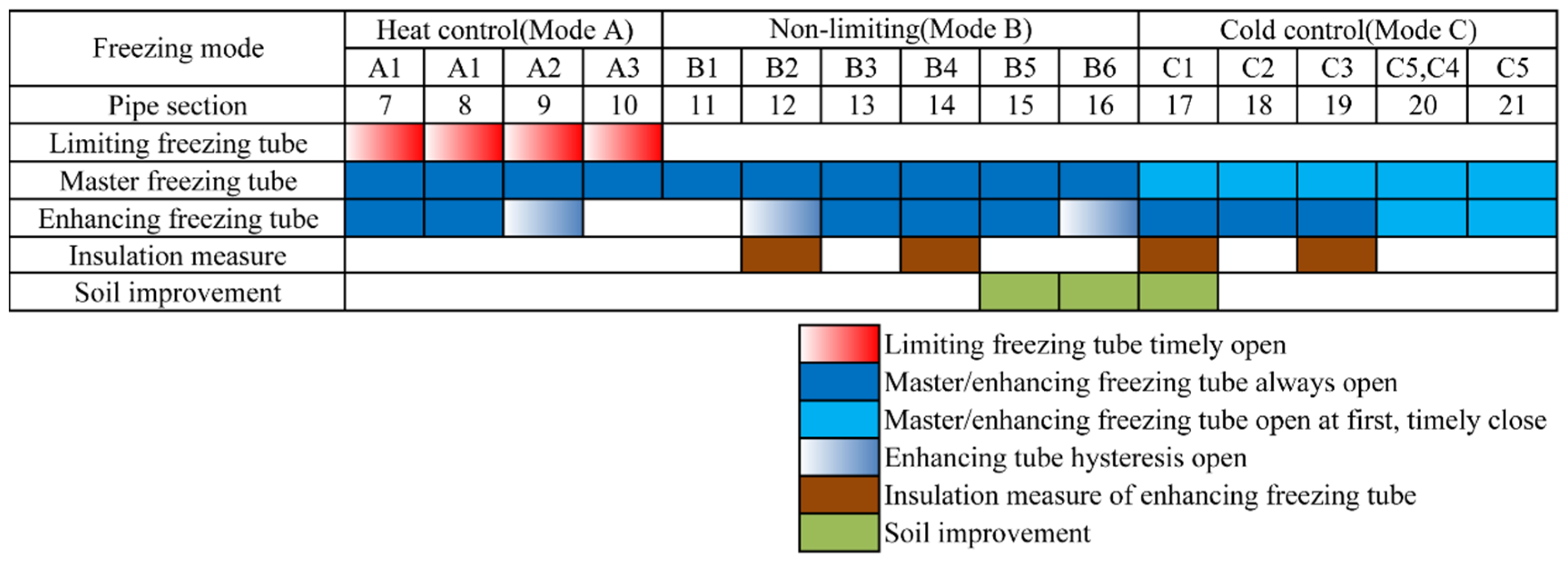
2.2.2. Freezing Test Scheme

There is no good condition to simulate the tunnel excavation; therefore, only the freezing scheme and control method were taken into account in the test. With the comparison of different freezing modes, the freezing scheme and process optimization of freezing method and the dynamic control method of freezing scheme are studied in the test.
The freeze process is a two-phase procedure: active freezing phase and maintained freezing phase. In the active freezing period, using master freezing tubes and enhancing freezing tubes is main method to form frozen soil curtain. According to the arrangements of freezing tubes in the curtain, the test in this paper studied the following four active freezing schemes: single freezing mode of the solid pipe, synergy freezing mode of the solid pipe and hollow pipe, principal freezing of the solid pipe with hollow pipe as complement and single freezing mode of the hollow pipe.
The single freezing mode of the solid pipe is to freeze the master freezing tubes in the solid pipe, and to verify the freezing effect under the condition that the master freezing tube works alone. The synergy freezing mode of the solid pipe and hollow pipe is to use master freezing tubes and enhancing freezing tubes at the same time to achieve the maximum freezing strength, so as to ensure the rapid formation of the frozen soil curtain as soon as possible. During the principal freezing of the solid pipe with the hollow pipe as a complement, it is necessary to open the enhancing freezing tubes in a timely fashion to improve the freezing strength with the master freezing tubes open. As a kind of optimized freezing mode, the effect of freezing and time control are worth exploring. Finally, the freezing mode of the hollow pipe is used to examine the freezing effect when the enhancing freezing tubes are opened only in the hollow pipe. In this phase, the brine temperature of the master freezing tubes and enhancing freezing tubes was maintained at −24 °C.
After active freezing, the phase of maintaining the freezing phase began. The design concept emphasized the importance to dynamically control the thickness of the frozen soil curtain during excavation. Therefore, maintaining the freezing phase is complex and important. There are two methods to control the freezing area, namely heat control and cold control. The difference between the two methods is controlling the freezing tubes or turning on limiting freezing tubes.
The heat control method recycled brine with relatively high (−2 °C–8 °C) temperature in limiting freezing tubes and then carried cold away, with the purpose of controlling the development of the curtain is thickness outward from the tunnel. In the heat control phase, the brine temperature of limiting freezing tubes was maintained at 2 °C. The cold control of frozen soil is realized by raising the brine temperature from −24 °C to −20 °C in the freezing system or changing the freezing mode of the master freezing tubes to reduce the cold produced by the cold source, which is named the intermittent freezing method.
In summary, the realization of heat control is based on providing an external heat source in the freezing area, while that of the cold one depends on the reduction of cold provided in unit time. In addition, the effect of soil improvement and insulation measure is also involved in this test.
To set a reasonable combination of active freezing phase and maintaining freezing phase, the whole test was divided into three main modes: non-limiting freezing, heat control limiting freezing and cold control limiting freezing. The controlling freeze schemes in the maintaining freezing phase are taken into consideration.
The difference among the three above modes is the measure taken to control the development of the frozen soil. The non-limiting freezing mode allows the infinite expansion of the frozen soil. The heat control limiting freezing mode turns on the limiting freezing tubes to control the development. The cold control mode control the thickness of frozen soil by raising the brine temperature in freezing tubes.
Figure 7 lists 14 types of detailed test. Different freezing schemes in the active freezing phase are made, three freezing modes in the maintaining freezing phase are considered. Besides, soil improvement and insulation measure are also involved in the test. Each of the above 14 types of freezing modes are arranged in only one pipe section with a length of 4 m to save cost and time. Meanwhile, insulation barriers are installed between each pipe section of #0 pipe to stop air convection and reduce interaction between them. Take pipe 7 for example, it belongs to A1 of Mode A (Heat control mode). When test begins, master freezing tubes and enhancing freezing tubes remain an opened state. If the thickness of the frozen soil is too large, it is necessary to keep limiting the opening of the freezing tube in a timely fashion to open to control the frost heave. Each test is arranged as follows.

2.2.3. Thawing Test Scheme

The natural thawing and artificial thawing test is next to the above freezing tests. Artificial thawing of frozen soil circles with normal brine in freezing area with master freezing tubes, limiting freezing tubes and enhancing freezing tubes takes cold away from the surrounding soil to realize thawing. Natural thawing is a natural warming process. Natural thawing and artificial thawing tests are conducted by fully or partially opening the master freezing tubes, limiting freezing tubes and enhancing freezing tubes. However, this paper mainly focuses on the active freezing phase and maintaining freezing phase of the in-situ test.

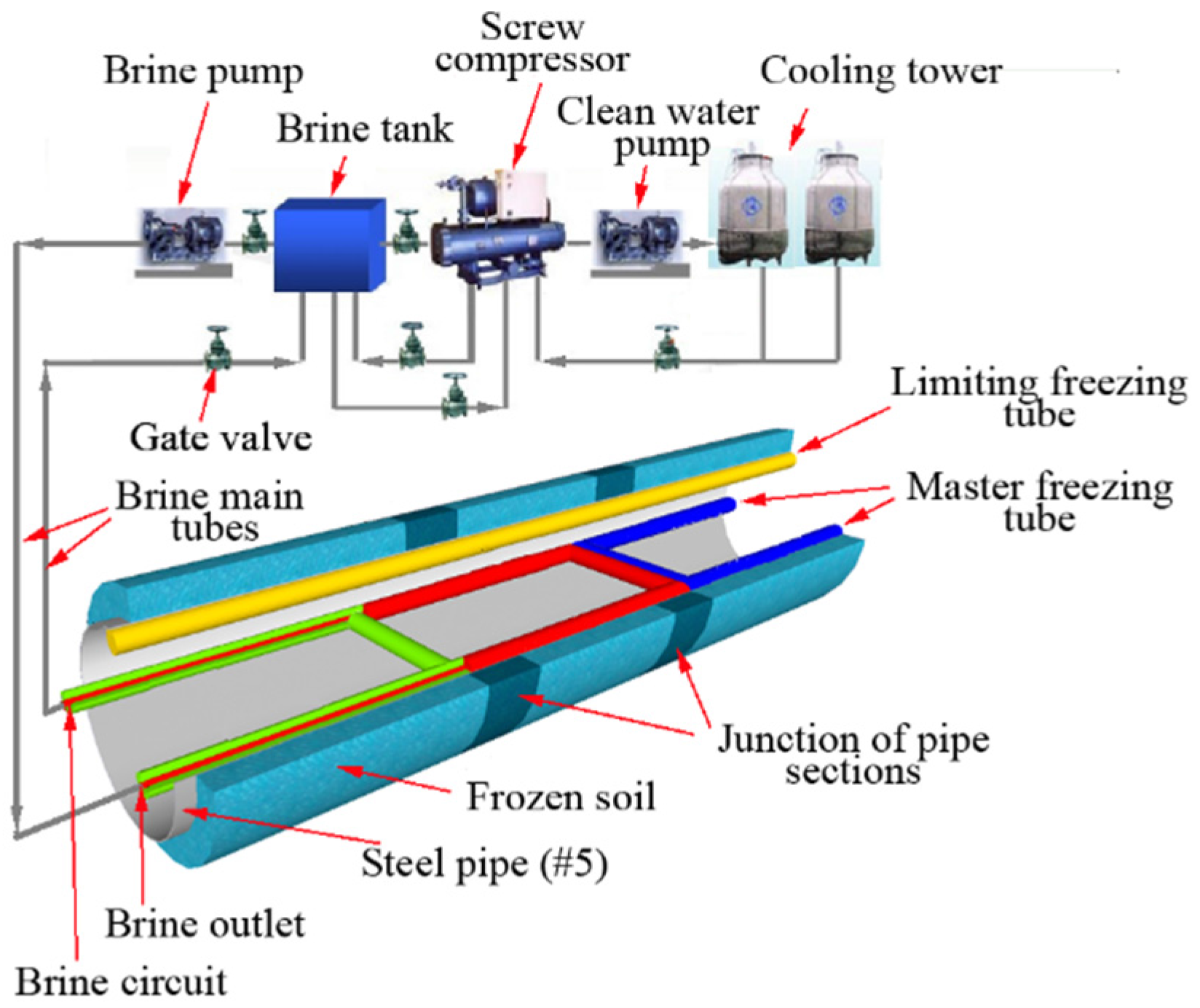
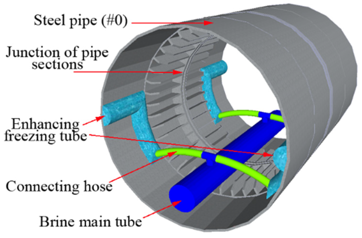
2.3. Freezing and Monitoring System

2.3.1. Freezing System

The freezing system is needed to realize the different freezing scheme. Two freezing technologies are available in the construction, either using brine or liquid nitrogen. The brine freezing system was adopted in this project. The brine freezing system is established in a freezing station. It is made up of a screw compressor, brine pump, clean water pump, brine tank, cooling tower, gate valve and two insulated brine main tubes, which were laid from the station to the freezing zone respectively for the delivery and circuit of brine, shown in Figure 8.
In this test, the brine was cooled down to the temperature of −24 °C in the refrigeration unit. Then it was sent to the proposed frozen zone and then warmer brine returning from the return pipe was cooled again and sent back to the delivery tube, forming a closed circuit. The cooled brine running through the freeze tubes continuously drew heat from the ground until the state of water changed from liquid to solid and the required temperature was reached.
In pipe #5, brine branch tubes were installed inside the master freezing tubes and limiting freezing tube to extend to different test pipe sections. Freezing control of different test pipe sections was realized by switching valves between test pipe sections, shown in Figure 8.
In Figure 9, the brine main tube was installed inside of the hollow pipe (#0) and the enhancing freezing tubes were connected with brine main tube by connecting hose. Freezing control of different test pipe sections was realized by switching valves in each test pipe section.

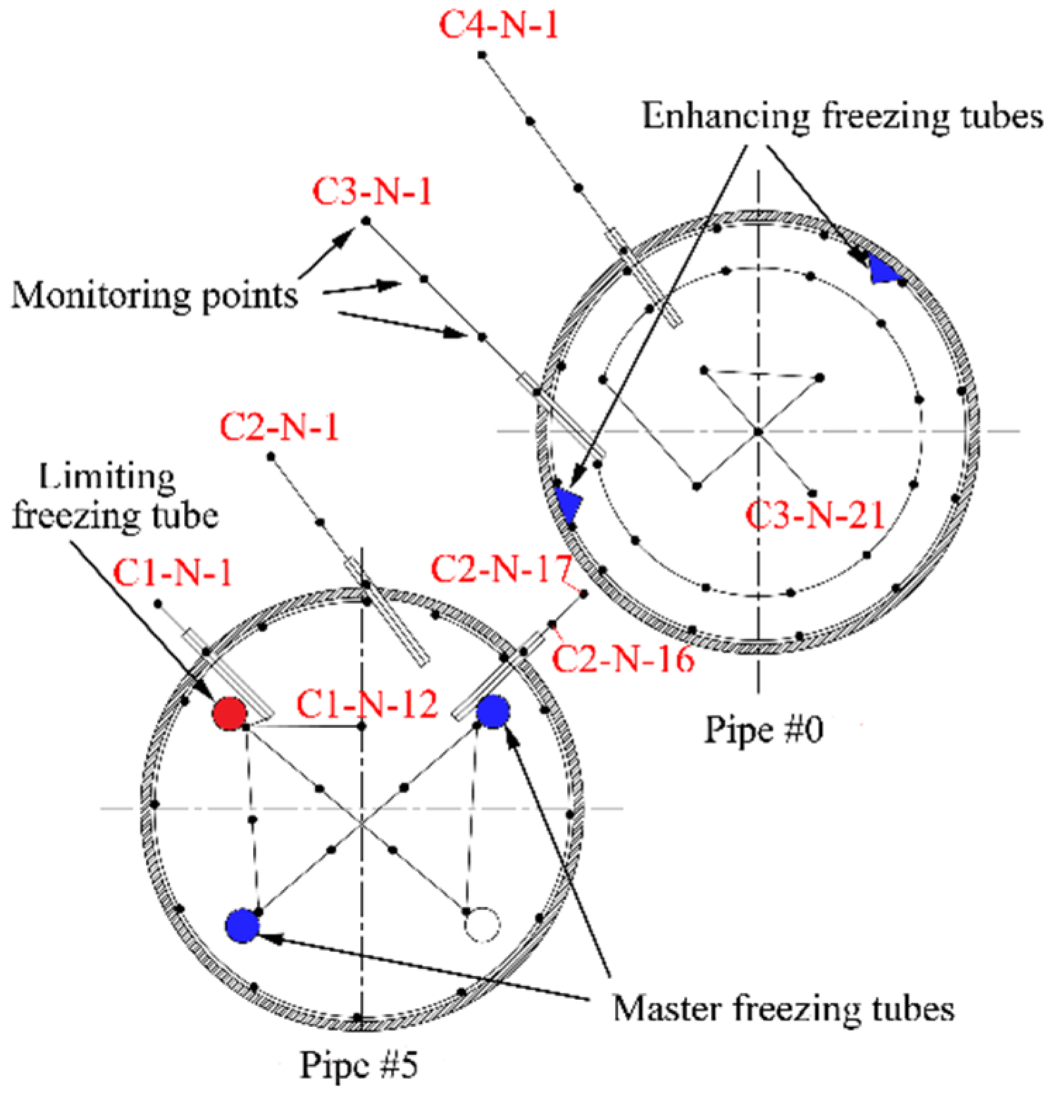
2.3.2. Monitoring System

Temperature is the reflection of the frozen soil curtain and the main parameter of the freezing effect. Brine temperature (temperature of brine in loops of master freezing tubes of solid pipe, limiting freezing tubes and enhancing freezing tubes), pipe-roof temperature (the inner wall temperature of solid pipe and hollow pipe, temperature of concrete in solid pipe and air in hollow pipe) and soil temperature outside the steel pipe-roof is monitored during the test.
The test adopts the “one-wire BUS” temperature measurement system, developed by the freeze monitoring group of Tongji University. Brine temperature is measured by temperature sensors installed in brine loops of main tubes of freezing station, limiting freezing tubes and enhancing freezing tubes. Temperature of the steel pipe-roof and soil is measured by thermometric cables installed in each pipe section with a total of 15 sections. The position of temperature monitoring points in each section is shown in Figure 10. Taking C2-N-16 as an example, C2 represents the number of the cable; N represents the number of the pipe section and 16 represents the number of temperature monitoring points in the corresponding cable.

3. Results and Discussion

Fourteen types of freezing schemes and 6 types of thawing schemes were carried out in in-situ test, which lasted for 5 months. And a large amount of data was obtained. Based on data analysis, a series of results have been obtained in the aspects of building up the frozen soil curtain, controlling the volume of frost heave. This part will introduce the main results from three aspects of time-temperature curve, cloud chart, and thickness of frozen soil curtain.

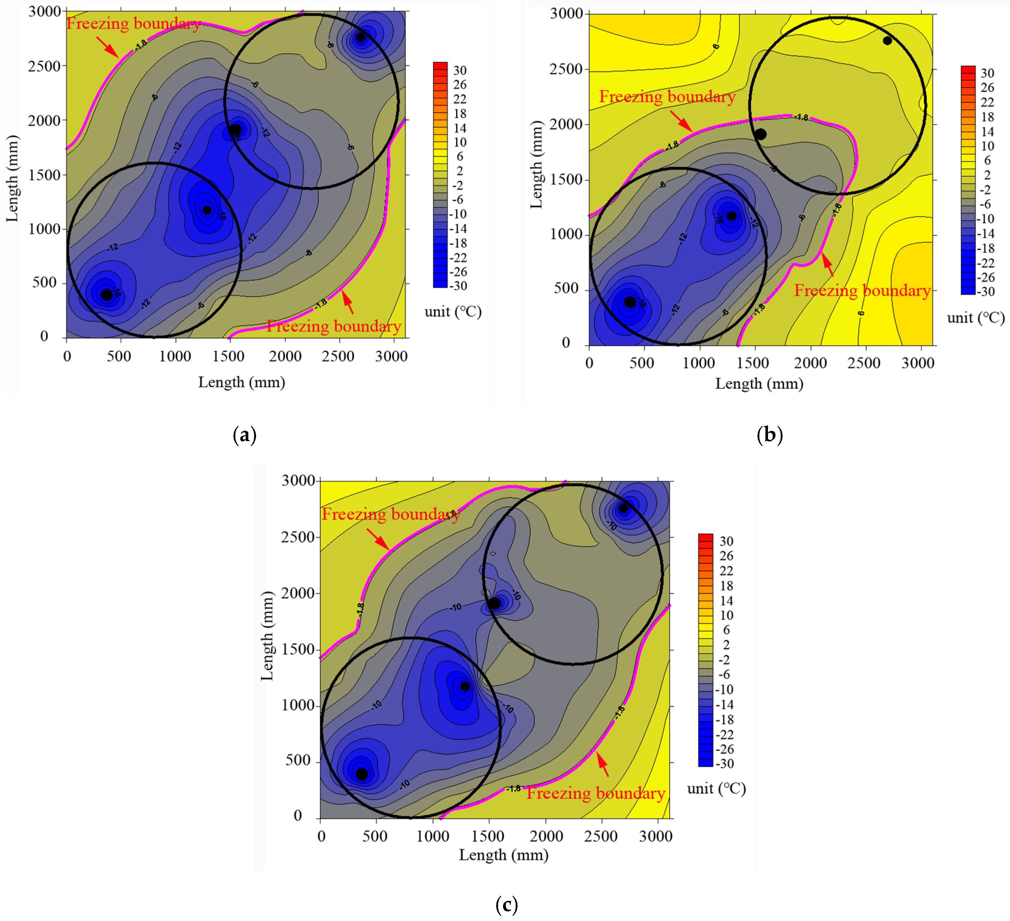
3.1. Active Freezing Phase

The frozen soil between pipe-roofs is the key region for water sealing. Therefore, the temperature of this region can reflect the sealing effect directly. Figure 11 shows the temperature change curve of the monitoring point of C2-N-16, which represents three freezing schemes during the active freezing phase. The development and thickness of the frozen soil curtain can be shown in Figure 12 [19,20].
In the synergy freezing mode of the solid pipe and hollow pipe, soil temperature between the pipe roofs experienced a rapid cool down in a short time. Frozen soil was shaped in about 10 days, and the completed water-sealing curtain was formed in around 20 days around. At the completion of active freezing for 60 days, the frozen soil curtain developed into bulge-like shape between pipes, shown in Figure 12a. The maximum thickness of frozen soil between the steel pipes reached 2.9 m, which met the design value of 2 m. The soil freezing effect between pipes was strengthened because of the synergy effect. Such a non-uniform profile of frozen soil obviously improved the sealing performance between steel pipes.
Compared with the synergy freezing mode, frozen soil was formed relatively slower in the single freezing mode of solid pipe. It took approximately 30 days for the monitoring points between steel pipes to reach the freezing point. After 45–50 days’ active freezing, a completed water-sealing curtain was formed. Meanwhile, according to Figure 12b, it can be seen from the cloud chart that the air temperature in the hollow pipe and the upper part of the hollow pipe was relatively higher, only the temperature of soil between steel pipes was below freezing point. Moreover, no frozen soil was formed in the upper part of the hollow pipe after 60 days of active freezing.
Through the comparison of the frozen soil development of the two above schemes after 60 days’ active freezing, the important role of enhancing tubes inside the hollow pipe was highlighted. Enhancing tubes will not only strengthen the freezing effect of soil between steel pipes, but also ensure the formation of frozen soil above the hollow pipe.
Many schemes were also carried out in the test. Principal freezing of the solid pipe with hollow pipe as a complement was simulated, which means the solid pipe as the main and the hollow pipe as the auxiliary. Figure 11 shows the time-temperature curve of soil between steel pipes with 39-day hysteresis opening of the enhancing freezing tubes. As is shown in this figure, after opening the enhancing freezing tubes, the cooling rate of soil between pipes has been significantly improved. At the end of the active freezing, the temperature of this region is almost equal to the temperature in the synergy freezing scheme of the solid pipe and hollow pipe. The maximum thickness of frozen soil between steel pipes reached 2.5 m, which met the minimum design value of 2 m. Besides, the comparison in Figure 11 also illustrates that the scheme of enhancing freezing tubes hysteresis opening can finally achieve the same freezing effect as the synergy scheme finally. Therefore, such a principal freezing scheme of the solid pipe with hollow pipe as complement can not only ensure the safety of the frozen soil curtain, but also realize freezing with subsection, reducing construction cost and saving energy.

3.2. Maintained Freezing Phase

Considering that the thickness of frozen soil is increasing in the synergy freezing scheme of the solid pipe and hollow pipe, it is necessary to adopt the control freezing scheme to realize the effective control of the frost heave. The test compared two freezing control schemes, heat control mode and cold control mode.
Heat control mode is the process of taking cold away from the freezing zone by circulating a relatively high brine temperature (2 °C) in the limiting freezing tube. Because of the heat source concentration, this mode has the most obvious control effect near the limiting freezing tube. Figure 13a shows the temperature cloud chart when the limiting freezing tube was opened for 20 days. Compared with that without being opened in Figure 12a, the soil temperature near the limiting freezing tube is significantly controlled, while there is no obvious difference in the distant region. This shows that the heat control mode had a local characteristic and had little effect on the temperature field of other regions. This heat control mode would have a better effect when the frozen soil near the solid pipe developed too fast and the thickness was too large.
The cold control mode is achieved by adjusting the freezing brine temperature from −24 °C to −20 °C. This mode will affect the freezing effect throughout the whole frozen regions due to the adjustment of the freezing cycle of the cold supply, which can be confirmed by the comparison of cloud chart in Figure 13b after 17 days of cold control and that in Figure 13a with heat control. Besides, the temperature gradient of temperature field is very different to that in the earlier situation, shown in Figure 13b. In a word, the cold control mode can not only control the thickness of frozen soil curtain, but also adjust the effect of temperature gradient across the whole temperature field.
If the frozen soil curtain was too thick or the boundary of the frozen soil developed rapidly during the freezing construction of the FSPR method, the cold control mode is suggested to achieve an overall effect of controlling frost heave.

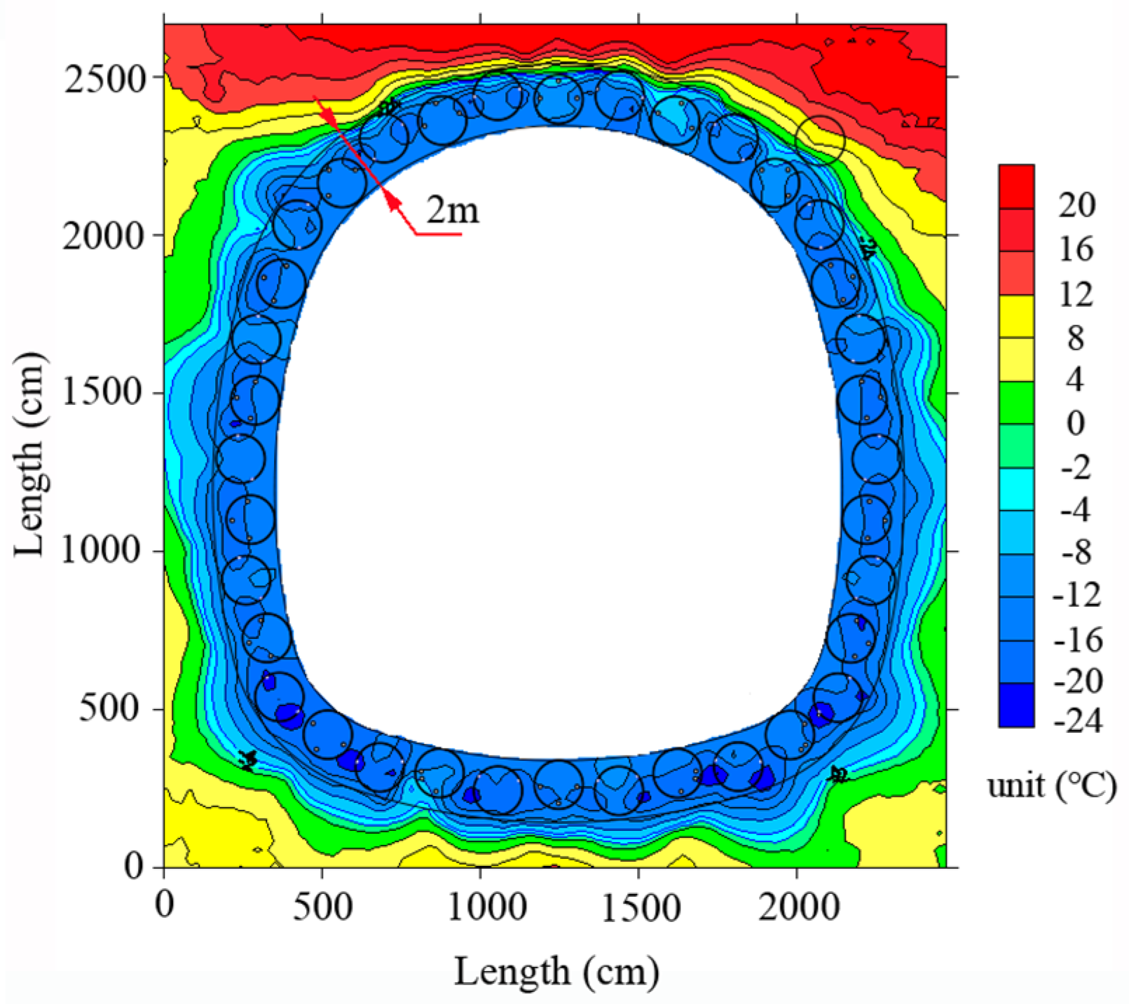
3.3. Actual Construction Condition

According to the test, the thickness of frozen soil between steel pipes can meet the design requirement after 60 days of freeze in the principal freezing scheme of the solid pipe with hollow pipe as a complement, which means master freezing tubes were first open at −24 °C with 39-day hysteresis opening of the enhancing freezing tubes. In actual construction conditions, the principal freezing scheme of the solid pipe with hollow pipe as a complement was adopted. The master freezing tubes were first opened at −24 °C with 38-day hysteresis opening of the enhancing freezing tubes. The minimum thickness of frozen soil between steel pipes met the design requirement of 2 m after 60 days of freeze, shown in Figure 14. The thickness continued to increase with time, and the cold control mode was adopted to control the thickness of frozen soil by moderately increasing the brine temperature. Based on the above, the freezing scheme of actual construction followed the study results of the in-situ test.

4. Conclusions

According to the time-temperature curve, cloud chart, thickness of frozen soil, the following conclusions can be drawn.
(1) The principal freezing scheme of the solid pipe with hollow pipe as a complement is the most optimal scheme among these three schemes, which can not only meet the requirement of this project after a 60 day freezing process, but also realize freezing with subsection, reducing construction cost and saving energy.
(2) The cold control mode is a more optimal scheme that will have an overall positive effect on controlling frost heave instead of local effects around limiting freezing tube.
(3) In-situ test results have been adopted in actual construction. Master freezing tubes were first opened at −24 °C with 38-day hysteresis opening of the enhancing freezing tubes. The cold control mode was adopted to control the thickness of frozen soil by moderately increasing the brine temperature.

Acknowledgments

The authors would like to acknowledge the financial support from National Natural Science Foundation of China (Grant No. 51478340), Science and Technology Program of Ministry of Transport of China (Grant No. 2013318J11300). The authors also wish to thank Longpeng He, Xiaodong Guo for the contribution to this test.

Author Contributions

Xiangdong Hu proposed the idea of this research work and conceived the tests; Shengjun Deng and Hui Ren performed the tests; Shengjun Deng wrote the paper.

Conflicts of Interest

The authors declare no conflict of interest.

References

  1. Shen, G.P.; Cao, W.H.; Yang, J.L.; Zhu, H.H. Review of Pipe-Roof Method. Geotech. Eng. World 2006, 9, 27–29. [Google Scholar]
  2. Kamakura, T.; Toshimitsu, A.; Hamaguchi, K.; Hiroaki, I. Development of tunnel expansion method (SR-J) for underground highway junction. Proc. Annu. Conf. Jpn. Soc. Civ. Eng. 2005, 60, 165–166. [Google Scholar]
  3. Hamaguchi, K.; Yabe, Y.; Kenji, Y. Development of small diameter shield combined large-section widening method. Proc. Annu. Conf. Jpn. Soc. Civ. Eng. 2006, 61, 139–140. [Google Scholar]
  4. Xing, K.; Chen, T.; Huang, C.B. On the new tubular roof method. Urban Mass Transit. 2009, 12, 63–67. [Google Scholar]
  5. Hu, X.D.; She, S.Y. Study of Freezing Scheme in Freeze-Sealing Pipe Roof Method Based on Numerical Simulation of Temperature Field. In Proceedings of the International Conference on Pipelines and Trenchless Technology, Wuhan, China, 19–22 October 2012; American Society of Civil Engineers: Reston, VA, USA, 2012; pp. 1798–1805. [Google Scholar]
  6. Yuan, J.; Chen, H. A New Method for Developing Large-section Underground Space by Small Diameter Pipe Jacking Machine-Pipe Roofing Method. Undergr. Eng. Tunn. 2004, 1, 23–26. [Google Scholar]
  7. Cheng, Y.; Liu, J.G. Design Scheme of Gongbei Tunnel. Highw. Tunn. 2012, 3, 34–38. [Google Scholar]
  8. Yu, J.; Cheng, Y.; Jia, R. Option Demonstration for the Gongbei Tunnel at the Zhuhai Link of the Hong Kong-Zhuhai-Macau Bridge. Mod. Tunn. Technol. 2012, 49, 119–125. [Google Scholar]
  9. Moriuchi, K.; Ueda, Y.; Ohrai, T. Influence of contact area between steel pipe and frozen soil on adfreeze strength. In Proceedings of the 2004 Conference Japanese Society of Snow and Ice, Kitami, Japan, 14–15 January 2004.
  10. Moriuchi, K.; Ueda, Y.; Ohrai, T. Influence of bending strain rate on response characteristics of frozen soil surrounding steel pipe. In Proceedings of the 2004 Conference Japanese Society of Snow and Ice, Kitami, Japan, 14–15 January 2004.
  11. Moriuchi, K.; Ueda, Y.; Ohrai, T. Study on the Ad freeze between Frozen Soil and Steel Pipes for Cutoff of Water. Doboku Gakkai Ronbunshuu C. 2008, 64, 294–306. [Google Scholar] [CrossRef]
  12. She, S.Y. The Preliminary Study of Freezing Scheme in Freeze-Sealing Pipe Roof Method Based on Unsteady Conjugate Heat Transfer. Master’s Thesis, Tongji University, Shanghai, China, 2013. [Google Scholar]
  13. Hu, X.D.; Fang, T. Numerical Simulation of Temperature Field at the Active Freeze Period in Tunnel Construction Using Freeze-Sealing Pipe Roof Method. In Proceedings of the Tunneling and Underground Construction, Shanghai, China, 26–28 May 2014; American Society of Civil Engineers: Reston, VA, USA, 2014; pp. 731–741. [Google Scholar]
  14. Wang, Y. Mechanical Property Analysis of Steel Pipe-Frozen Soil Composite Structure in Freeze-Sealing Pipe Roof Method. Master’s Thesis, Tongji University, Shanghai, China, 2013. [Google Scholar]
  15. Chen, J. Large Scaled Model Test Study on Freezing Scheme of Freeze-Sealing Pipe Roof. Master’s Thesis, Tongji University, Shanghai, China, 2013. [Google Scholar]
  16. Hu, X.D.; Ren, H.; Chen, J.; Cheng, Y.; Zhang, J. Model Test Study of the Active Freezing Scheme for the Combined Pipe-Roof and Freezing Method. Mod. Tunn. Technol. 2014, 51, 92–98. [Google Scholar]
  17. Zhang, J.; Hu, X.D.; Wang, W.Z. The Design of Super Long, Refined and Dynamic Controlled Horizontal Ground Freezing Used for Water-sealing in Gong-bei Tunnel. In Proceedings of Underwater Construction and Management, Nanjing, China, 28 November 2013; pp. 245–251.
  18. Hu, X.D.; Fang, T. Numerical Simulation of Temperature Field at the Excavation and Primary Support Period in Tunnel Construction Using Freeze-Sealing Pipe Roof Method. In Proceedings of Underwater Construction and Management, Nanjing, China, 28 November 2013; pp. 72–79.
  19. Hu, X.D.; Guo, X.D.; Wang, Q.T.; Ren, H.; He, L.; Deng, S. Field Test Study on Freezing Technology of Freeze-Sealing Pipe Roof. Tunn. Constr. 2015, 35, 1–7. [Google Scholar]
  20. Ren, H. In-Situ Prototype Test Study on Freezing Scheme of Freeze-Sealing Pipe Roof. Master’s Thesis, Tongji University, Shanghai, China, 2015. [Google Scholar]
Figure 1. The alignment of Gongbei tunnel.
Applsci 07 00027 g001
Figure 2. Geotechnical profile of Gongbei Tunnel.
Applsci 07 00027 g002
Figure 3. Arrangement of the pipe-roofing.
Applsci 07 00027 g003
Figure 4. The layout of freezing tubes.
Applsci 07 00027 g004
Figure 5. The arrangement of freezing test area in the in-situ test.
Applsci 07 00027 g005
Figure 6. The arrangement of freezing tubes in the test pipes.
Applsci 07 00027 g006
Figure 7. The arrangement of freezing scheme.
Applsci 07 00027 g007
Figure 8. Layout of freezing system.
Applsci 07 00027 g008
Figure 9. Freezing tube layout of hollow pipe (#0).
Applsci 07 00027 g009
Figure 10. Position of monitoring points.
Applsci 07 00027 g010
Figure 11. The time-temperature curve of soil between steel pipes (C2-N-16).
Applsci 07 00027 g011
Figure 12. Cloud chart of temperature field of active freeze period after 60 days’ freeze: (a) Cloud chart of synergy freezing of the solid pipe and hollow pipe; (b) Cloud chart of single freezing of the solid pipe; (c) Cloud chart of principal freezing of the solid pipe with hollow pipe as complement.
Applsci 07 00027 g012
Figure 13. The effect of controlling freeze (after being controlled for 17 days). (a) Heat control mode; (b) Cold control mode.
Applsci 07 00027 g013
Figure 14. Temperature field of actual construction condition.
Applsci 07 00027 g014
Table 1. Soil parameters of the test region.
Soilγ (kN/m3)Granulometry (mm)PorosityPermeability (cm/s)
Sludge and mucky soil180.005–0.050.30–0.652.87 × 10−8–2.29 × 10⁻⁷
Clay20<0.0050.45–0.654.98 × 10−6

